EP4530045A1 - Unité de moulage par soufflage pour une installation de moulage par soufflage - Google Patents
Unité de moulage par soufflage pour une installation de moulage par soufflage Download PDFInfo
- Publication number
- EP4530045A1 EP4530045A1 EP23200420.0A EP23200420A EP4530045A1 EP 4530045 A1 EP4530045 A1 EP 4530045A1 EP 23200420 A EP23200420 A EP 23200420A EP 4530045 A1 EP4530045 A1 EP 4530045A1
- Authority
- EP
- European Patent Office
- Prior art keywords
- blow
- interface
- blow mold
- media
- unit according
- Prior art date
- Legal status (The legal status is an assumption and is not a legal conclusion. Google has not performed a legal analysis and makes no representation as to the accuracy of the status listed.)
- Pending
Links
Images


Classifications
-
- B—PERFORMING OPERATIONS; TRANSPORTING
- B29—WORKING OF PLASTICS; WORKING OF SUBSTANCES IN A PLASTIC STATE IN GENERAL
- B29C—SHAPING OR JOINING OF PLASTICS; SHAPING OF MATERIAL IN A PLASTIC STATE, NOT OTHERWISE PROVIDED FOR; AFTER-TREATMENT OF THE SHAPED PRODUCTS, e.g. REPAIRING
- B29C49/00—Blow-moulding, i.e. blowing a preform or parison to a desired shape within a mould; Apparatus therefor
- B29C49/42—Component parts, details or accessories; Auxiliary operations
- B29C49/48—Moulds
- B29C49/4823—Moulds with incorporated heating or cooling means
-
- B—PERFORMING OPERATIONS; TRANSPORTING
- B29—WORKING OF PLASTICS; WORKING OF SUBSTANCES IN A PLASTIC STATE IN GENERAL
- B29C—SHAPING OR JOINING OF PLASTICS; SHAPING OF MATERIAL IN A PLASTIC STATE, NOT OTHERWISE PROVIDED FOR; AFTER-TREATMENT OF THE SHAPED PRODUCTS, e.g. REPAIRING
- B29C49/00—Blow-moulding, i.e. blowing a preform or parison to a desired shape within a mould; Apparatus therefor
- B29C49/42—Component parts, details or accessories; Auxiliary operations
- B29C49/48—Moulds
- B29C2049/4879—Moulds characterised by mould configurations
- B29C2049/4892—Mould halves consisting of an independent main and bottom part
-
- B—PERFORMING OPERATIONS; TRANSPORTING
- B29—WORKING OF PLASTICS; WORKING OF SUBSTANCES IN A PLASTIC STATE IN GENERAL
- B29C—SHAPING OR JOINING OF PLASTICS; SHAPING OF MATERIAL IN A PLASTIC STATE, NOT OTHERWISE PROVIDED FOR; AFTER-TREATMENT OF THE SHAPED PRODUCTS, e.g. REPAIRING
- B29C49/00—Blow-moulding, i.e. blowing a preform or parison to a desired shape within a mould; Apparatus therefor
- B29C49/42—Component parts, details or accessories; Auxiliary operations
- B29C49/56—Opening, closing or clamping means
- B29C2049/566—Locking means
-
- B—PERFORMING OPERATIONS; TRANSPORTING
- B29—WORKING OF PLASTICS; WORKING OF SUBSTANCES IN A PLASTIC STATE IN GENERAL
- B29C—SHAPING OR JOINING OF PLASTICS; SHAPING OF MATERIAL IN A PLASTIC STATE, NOT OTHERWISE PROVIDED FOR; AFTER-TREATMENT OF THE SHAPED PRODUCTS, e.g. REPAIRING
- B29C2949/00—Indexing scheme relating to blow-moulding
- B29C2949/07—Preforms or parisons characterised by their configuration
- B29C2949/0715—Preforms or parisons characterised by their configuration the preform having one end closed
-
- B—PERFORMING OPERATIONS; TRANSPORTING
- B29—WORKING OF PLASTICS; WORKING OF SUBSTANCES IN A PLASTIC STATE IN GENERAL
- B29C—SHAPING OR JOINING OF PLASTICS; SHAPING OF MATERIAL IN A PLASTIC STATE, NOT OTHERWISE PROVIDED FOR; AFTER-TREATMENT OF THE SHAPED PRODUCTS, e.g. REPAIRING
- B29C49/00—Blow-moulding, i.e. blowing a preform or parison to a desired shape within a mould; Apparatus therefor
- B29C49/02—Combined blow-moulding and manufacture of the preform or the parison
- B29C49/06—Injection blow-moulding
-
- B—PERFORMING OPERATIONS; TRANSPORTING
- B29—WORKING OF PLASTICS; WORKING OF SUBSTANCES IN A PLASTIC STATE IN GENERAL
- B29C—SHAPING OR JOINING OF PLASTICS; SHAPING OF MATERIAL IN A PLASTIC STATE, NOT OTHERWISE PROVIDED FOR; AFTER-TREATMENT OF THE SHAPED PRODUCTS, e.g. REPAIRING
- B29C49/00—Blow-moulding, i.e. blowing a preform or parison to a desired shape within a mould; Apparatus therefor
- B29C49/28—Blow-moulding apparatus
- B29C49/30—Blow-moulding apparatus having movable moulds or mould parts
- B29C49/36—Blow-moulding apparatus having movable moulds or mould parts rotatable about one axis
-
- B—PERFORMING OPERATIONS; TRANSPORTING
- B29—WORKING OF PLASTICS; WORKING OF SUBSTANCES IN A PLASTIC STATE IN GENERAL
- B29L—INDEXING SCHEME ASSOCIATED WITH SUBCLASS B29C, RELATING TO PARTICULAR ARTICLES
- B29L2031/00—Other particular articles
- B29L2031/712—Containers; Packaging elements or accessories, Packages
- B29L2031/7158—Bottles
Definitions
- the present invention relates to a blow molding unit for a blow molding system for forming plastic preforms into containers with a blow mold and a blowing device associated with the blow mold, wherein the blow mold is formed from a first and at least one second blow mold part, which can be pivoted relative to one another between the open and closed positions.
- the invention relates to a blow molding unit used in blow molding systems for the beverage industry, wherein beverage containers, in particular beverage bottles, are then formed from the preforms.
- blow molding units are usually arranged on a conveyor carousel, wherein, during the rotation of the conveyor carousel, the preforms are first inserted into the blow mold and then the interior of the preforms is pressurized with compressed air. By applying internal pressure, the walls of the preforms are pressed outwards into a blow cavity formed by the blow mold parts, which corresponds to the shape of the beverage bottles to be produced.
- a stretch rod can also be provided, which is successively inserted into the blow mold along the container axis and enables a certain axial elongation of the preforms.
- stretch blow molding Such a process is also referred to as stretch blow molding, and the systems are referred to as stretch blow molding systems.
- the blow molds consist of at least two blow mold parts, which together form a blow cavity. It is within the scope of the invention that the blow mold parts are each made in one piece or can be constructed in multiple parts, with a multi-part design comprising, in particular, a mold carrier and a format part arranged in the mold carrier, and the actual blow mold cavity being formed via the format part.
- a multi-part design comprising, in particular, a mold carrier and a format part arranged in the mold carrier, and the actual blow mold cavity being formed via the format part.
- blow mold parts are usually connected to one or more media supplies, whereby in the context of the invention, media means both fluid media and electrical media.
- media means both fluid media and electrical media.
- the neck ring is a protruding ring below an external thread of the preform, wherein the external thread is designed to accommodate a closure cap. Accordingly, this is an area that is already prefabricated and which should not be deformed during blow molding. This can be ensured by active cooling.
- the molds To enable such temperature control during blow molding, the molds must be connected to a media supply. After assembly, appropriate supply lines are attached to the blow mold parts, which are fixed during operation of the blow molding units. However, it should be noted that the frequent pivoting movement of the blow mold parts during opening and closing of the mold also subjects the lines to considerable stress, which means they must be checked at regular intervals and replaced if necessary.
- the object of the invention is to provide a blow molding unit which is characterized by lower maintenance requirements.
- blow molding unit according to patent claim 1. Accordingly, it is provided that the first and/or the second blow molding part is connected to a media supply via a media interface in the closed position and is decoupled from the media supply in the open position.
- the invention is based on the realization that it is not absolutely necessary to supply the blow mold with various media when the mold is open, particularly since the open state exists for a significantly shorter time interval compared to the closed state. This short time interval is generally not sufficient to cool the blow mold parts. As soon as the mold is returned to the closed state, the individual media are supplied again.
- Such a design can advantageously prevent the lines or hoses required for supply from being subjected to strong movements and thus stresses, since instead of a moving Media line, the media interface is completely decoupled.
- the invention is not limited to embodiments in which the blow mold is formed exclusively from two blow mold parts. Rather, according to a conventional embodiment, the invention also provides for at least three blow mold parts, one of which is designed as a base part. The assignment to the first or second blow mold part is freely selectable, so that the base part can represent a first or a second blow mold part.
- the media interface comprises a first interface part arranged on the first or second blow mold part, which can be connected to a second interface part connected to the media supply in the closed position. Accordingly, it is clear that the media interface is not formed exclusively in one blow mold part. Rather, it consists of at least two interface parts, which are located in the blow mold part on the one hand and assigned to the corresponding media supply on the other.
- the type of media interface and thus also the type of interface parts depend essentially on the type of medium.
- the media interface is designed as a fluid connection
- the first interface part connects to a fluid channel arranged in the first and/or second blow mold part.
- the media interface and thus also the interface parts are components intended to transfer a fluid between the media supply and the respective blow mold part.
- a fluid refers to any type of medium. which is in a gaseous and/or liquid state. In particular, this includes water, steam, or compressed air, whereby the type of fluid depends on the intended purpose, which is described in more detail below.
- a particularly preferred embodiment provides that the fluid channel connects to a media interface or a first interface part at both ends, so that at least two media interfaces are provided on the blow molded part.
- One of the media interfaces then enables a corresponding connection to the media supply.
- a connection to a return line of the media supply can be established via the second media interface.
- the blow molded part is supplied with a fluid via the media supply, so that one corresponding media interface is understood as the inlet to the blow molded part and the other media interface as the outlet.
- a temperature control device means a device that can actively temperature control, heat and/or cool a fluid.
- the blow molded part is supplied with a fluid via the inlet, which is accordingly designed as a temperature control fluid and which is removed via the other media interface after flowing through the fluid channel.
- the fluid is returned to the temperature control device, where it is then heated or cooled again.
- the temperature control fluid is preferably water or steam.
- Other fluids used for heating or cooling are also generally suitable as temperature control fluids.
- the fluid channel is open at an end opposite the media interface.
- the fluid channel is connected to the media supply at only one end, with no connection to another device being provided at the opposite end.
- the fluid can then be used to push the already completely formed preform or the beverage bottle out of the blow cavity.
- the fluid is preferably compressed air.
- the open end of the fluid channel can end either at the lateral blow mold parts or at a base part, so that the container is pushed out either laterally and/or upwards.
- the media supply is accordingly a compressed air supply and not a temperature control device.
- the at least one media interface is designed as a fluid connection
- the problem arises that when the media interface or the interface parts are decoupled from one another, the respective fluid can still enter the blow mold because the second interface part continues to be supplied with a fluid via the media supply.
- a design is disadvantageous, particularly in connection with a temperature control fluid, so that a preferred development of the invention provides that the first and/or the second interface part is designed to be fluid-tight in the open position.
- a fluid-tight design means that the fluid channel within the blow mold part or any connections of the media supply to the second interface part are closed to the outside, so that no fluid can escape from the blow mold parts or from the media supply.
- first and/or the second interface part contains a valve body which is designed to be closed in the open position and opened in the closed position of the blow mold part.
- a valve body which is designed to be closed in the open position and opened in the closed position of the blow mold part.
- such a design can also be useful in combination with the first interface part, especially if it is intended to prevent residual fluid from escaping from the fluid channels of the blow-molded part.
- At least one media interface is designed as an electrical connection, wherein the first interface part connects to at least one electronic consumer on or in the first and/or the second blow mold part.
- electrical current or an electrical signal can thus be transmitted via the media interface.
- the electrical connection is a connection of electrical conductors which can be coupled to one another via the media interface.
- a media interface is not limited to merely to connect a conductor.
- the media interface or electrical connection can also enable the coupling of multiple conductors or wires.
- Such a configuration can be used for various applications, with a preferred configuration providing that the electrical load is a temperature control device and/or a measuring device.
- the electrical load is a temperature control device and/or a measuring device.
- the temperature control device is arranged outside the blow mold and serves to control the temperature of a temperature control fluid.
- This temperature control fluid is then fed to a blow molded part via the media interface, with the temperature control fluid in the fluid channels causing heating or cooling of the blow molded part.
- the temperature control device can also be at least one heating coil, which heats up due to its electrical resistance when a voltage is applied. Accordingly, these heating coils arranged in the blow mold part are coupled to a media supply or power supply via the electrical connection and enable heating of the corresponding blow mold part when the mold is closed.
- Such a design has the advantage over previous solutions that the heating coils are safely disconnected from the power supply when the mold is open, thus ensuring a high degree of safety for the user even in the event of any damage to the insulation.
- unlike designs with a temperature control fluid there is no need to separately ensure that the fluid channels are sealed to the outside when the mold is open in order to prevent the temperature control fluid from escaping.
- a measuring device can comprise a variety of possible measuring sensors or be designed accordingly as a measuring sensor.
- This measuring sensor can, for example, be a temperature sensor that detects the temperatures of the blow mold parts. Alternatively, it can also be simple measuring sensors that detect the closed or open state of the blow mold.
- the interface parts are designed as plug-in connections.
- the first or second interface part is designed as a male connector
- the other interface part is designed as a female connector, so that they can engage with each other in the closed state to enable electrical contact.
- spring-loaded pins can also be used, which are attached to contact plates.
- a further development of the invention provides that the interconnectable interface parts of at least one media interface are arranged on the first and second blow mold parts.
- one of the blow mold parts then has the first interface, and the other blow mold part has the second interface part, so that media transfer occurs between the blow mold parts.
- one blow mold part is preferably firmly connected to the media supply, while another blow mold part is coupled to the media supply via the other blow mold part.
- the second blow mold part can be firmly coupled to the media supply in both an open and a closed state, while the first blow mold part can only be via which the second blow molded part is coupled to the media supply.
- a stationary design means that the second blow mold part does not actively participate in the pivoting movement. Rather, the opening and closing of the blow mold takes place solely via a pivoting movement of the first blow mold part. Based on this, the first interface part of at least one media interface can then be arranged on the first blow mold part. The second interface part is then preferably formed accordingly on the second blow mold part.
- a corresponding media interface for the second blow mold part is not subject to the particularly high loads during a pivoting movement, so that the connection of the second blow mold part to the media supply can be made in a known, permanently installed manner.
- blow mold parts can be locked together in the closed position via at least one locking device.
- a locking device makes it possible to prevent the blow mold parts from pivoting apart. This is particularly important during the blow molding process.
- Such a locking device preferably not only allows the blow molds to pivot apart but also to lock them together. Locking means that the blow mold parts are pressed together with a specific pressure.
- the locking device not only This not only provides a locking mechanism but also simultaneously couples the interface components to one another.
- the media interfaces it is also within the scope of the invention for the media interfaces to be separated from the locking device and, for example, arranged next to it.
- connection block connected to the media supply is provided with at least one second interface part, wherein the first and/or the at least second blow mold part are each connected to the connection block in the closed position via a first interface.
- first and/or the at least second blow mold part are each connected to the connection block in the closed position via a first interface.
- both blow mold parts are designed to be pivotable, so that both blow mold parts can then be pivoted against this connection block and the corresponding interface parts are coupled to one another.
- one blow mold part is designed to be stationary, in which case the first or the second interface part is designed as a base part.
- the connection block can preferably be mounted on the stationary blow mold part or separately on the blow molding unit.
- the invention further relates to a blow molding system with at least one blow molding unit according to the invention, wherein the at least one blow molding unit is arranged on a rotatably driven carrier.
- a drive device which effects a closing movement and an opening movement between the blow mold parts.
- the drive device is preferably a cam-controlled drive device, so that the movement is effected solely on the basis of the Rotation of the blow molding units on the rotatably driven carrier is effected.
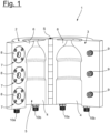
- the Fig. 1 shows a blow mold 1 for a blow molding unit of a blow molding system for forming plastic preforms into beverage containers.
- the blow molding unit additionally has a blowing device (not shown) via which the blow mold 1 or a preform arranged in the blow mold 1 can be subjected to compressed air, so that a beverage container, in particular a beverage bottle, can be formed from it.
- the blow mold 1 consists of a first and a second blow mold part 2, 3, each of which has a molding 4 for the joint formation of a blow cavity 5.
- This blow cavity 5 essentially corresponds to the shape of the container to be manufactured.
- the two blow mold parts 2, 3 are also pivotable relative to each other via a pivot axis S, so that the blow mold 1 can be moved between an open and a closed position.
- Fig. 1 In this context, the opening position of the blow mold 1 is shown.
- blow molding unit and thus also the blow mold 1
- a rotatable support also not shown in detail
- the preforms are formed into beverage containers during rotating transport on the support.
- This requires the blow mold parts 2, 3 to pivot toward or away from each other at defined angular positions.
- the preforms are inserted in the open position shown.
- This contact surface 6 defines a parting plane between the blow mold parts 2, 3, in which they must be pressed together using a sufficiently large contact force so that a clean forming of the preforms can take place along this parting plane.
- locking devices 7 are provided, by means of which the blow mold parts 2, 3 are locked together and pressed together in the closed position.
- These locking devices 7 each consist of a chuck 8 and an associated clamping bolt 9, wherein the chuck 7 is located in the first blow mold part 2 and the clamping bolts 9 in the second blow mold part 3. During the closing movement, the clamping bolts 9 are then each inserted into an opening of the associated chuck 7 and held there.
- media interfaces 10a, 10b are also provided, via which fluid channels formed in the blow mold parts 2, 3 are coupled to a media supply.
- the media supply is a fluid supply, e.g., of a temperature control device, to which a temperature-controlled fluid or a temperature control fluid is provided.
- This temperature control fluid flows via the media interfaces 10a into the respective blow mold part 2, 3 and out again via the media interface 10b.
- the media interfaces 10a, 10b are usually firmly connected to the media supply during assembly, so that the lines connected to them move along during the pivoting movement.
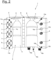
- Fig. 2 an embodiment according to the invention in which only the second blow mold part 3 is formed with fixed media interfaces 10a, 10b, 10c, wherein the media interface 10c, in contrast to the media interfaces 10a, 10b, is formed as an electrical connection and thus enables the transmission of an electrical signal.
- the media interfaces 10a, 10b, 10c each consist of a first interface part 11a, 11b and a second interface part 12a, 12b, which couple the media interfaces 10a, 10b to a media supply in the closed position and in the open position from the Decouple the media supply, whereby in this context reference is made exclusively to the first blow mold part 2.
- the interface parts 11a, 11b, 12a, 12b are correspondingly connected to fluid channels within the blow mold parts 2, 3, whereby in the closed position the fluid, e.g. a temperature control fluid, is then transferred via the interface parts 11a, 12a to the first blow mold part 2 and returned via the interface parts 11b, 12b to the second blow mold part.
- the interface parts 12a, 12b are designed to be fluid-tight to the outside in an open position, so that no fluid can escape from the blow-molded part 3 in an open position.
- the first interface parts 11a, 11b can also be designed to be fluid-tight.
- first blow mold part 2 also has a first interface part 11c and the second blow mold part has a second interface part 12c, via which electrical contact is made possible.
- This electrical contact is designed as a plug connection, with the male pins of the second interface part 12c engaging in receptacles of the first interface part 11c.
- the first interface part 11c is also integrated into a locking device 7 or into the chuck 8.
- the Fig. 3 shows a configuration with a total of three blow mold parts 2, 3, 13, wherein in this case the second blow mold part 3 is designed as a base part.
- the locking devices 7 then act between the first blow mold part 2 and the third blow mold part 13, wherein the clamping bolts 9 in this case are in the first blow mold part 2 and the clamping chucks 8 in the third blow mold part 13 are arranged.
- the second blow mold part 3 is pivoted relative to the first and third blow mold parts 2, 13, with the second blow mold part 3 having fixed media connections 10a, 10b.
- the first and third blow mold parts 2, 13 are then connected in such a way that the second blow mold part 3 has a total of four first interface parts 11a, 11b, each of which engages in associated second interface parts 12a, 12b in the first and third blow mold parts 2, 13.
- the Figure 4 shows a blow mold 1 according to the invention with a connection block 14, wherein the connection block 14 has a second interface part 12c on both sides as part of a media interface 10c, and via which electrical data can be transmitted.
- first interface parts 11c are provided on the first and second blow mold parts 2, 3, which according to the Figure 4 in the closed position interact with the second interface parts 12c and wherein the media interfaces 10c are designed as plug connections.
Landscapes
- Engineering & Computer Science (AREA)
- Manufacturing & Machinery (AREA)
- Mechanical Engineering (AREA)
- Moulds For Moulding Plastics Or The Like (AREA)
- Blow-Moulding Or Thermoforming Of Plastics Or The Like (AREA)
Priority Applications (1)
| Application Number | Priority Date | Filing Date | Title |
|---|---|---|---|
| EP23200420.0A EP4530045A1 (fr) | 2023-09-28 | 2023-09-28 | Unité de moulage par soufflage pour une installation de moulage par soufflage |
Applications Claiming Priority (1)
| Application Number | Priority Date | Filing Date | Title |
|---|---|---|---|
| EP23200420.0A EP4530045A1 (fr) | 2023-09-28 | 2023-09-28 | Unité de moulage par soufflage pour une installation de moulage par soufflage |
Publications (1)
| Publication Number | Publication Date |
|---|---|
| EP4530045A1 true EP4530045A1 (fr) | 2025-04-02 |
Family
ID=88236507
Family Applications (1)
| Application Number | Title | Priority Date | Filing Date |
|---|---|---|---|
| EP23200420.0A Pending EP4530045A1 (fr) | 2023-09-28 | 2023-09-28 | Unité de moulage par soufflage pour une installation de moulage par soufflage |
Country Status (1)
| Country | Link |
|---|---|
| EP (1) | EP4530045A1 (fr) |
Citations (4)
| Publication number | Priority date | Publication date | Assignee | Title |
|---|---|---|---|---|
| US8069545B2 (en) * | 2008-01-16 | 2011-12-06 | Krones Ag | Method for changeover of a blow molding machine |
| DE102017119817A1 (de) * | 2017-08-29 | 2019-02-28 | Krones Ag | Vorrichtung und Verfahren zum An- und Abkuppeln von Medienkupplungen an der Bodenform |
| US20210394422A1 (en) * | 2018-09-27 | 2021-12-23 | Krones Ag | Apparatus and method for forming plastic preforms into plastic containers with load compensation for media connections |
| US20220258405A1 (en) * | 2021-02-16 | 2022-08-18 | Sacmi Imola S.C. | Device for blow molding containers |
-
2023
- 2023-09-28 EP EP23200420.0A patent/EP4530045A1/fr active Pending
Patent Citations (4)
| Publication number | Priority date | Publication date | Assignee | Title |
|---|---|---|---|---|
| US8069545B2 (en) * | 2008-01-16 | 2011-12-06 | Krones Ag | Method for changeover of a blow molding machine |
| DE102017119817A1 (de) * | 2017-08-29 | 2019-02-28 | Krones Ag | Vorrichtung und Verfahren zum An- und Abkuppeln von Medienkupplungen an der Bodenform |
| US20210394422A1 (en) * | 2018-09-27 | 2021-12-23 | Krones Ag | Apparatus and method for forming plastic preforms into plastic containers with load compensation for media connections |
| US20220258405A1 (en) * | 2021-02-16 | 2022-08-18 | Sacmi Imola S.C. | Device for blow molding containers |
Similar Documents
| Publication | Publication Date | Title |
|---|---|---|
| EP2144742B1 (fr) | Dispositif de moulage par soufflage de récipients | |
| EP2383102B1 (fr) | Machine de soufflage-étirage | |
| EP2292403B1 (fr) | Procédé et dispositif de démontage de moules de soufflage | |
| EP1979153B1 (fr) | Dispositif de moulage par soufflage de recipients dote d'elements de transport de type pince a deux bras | |
| EP2292405B1 (fr) | Procédé et dispositif de montage et/ou de démontage de moules de soufflage | |
| EP1299223B1 (fr) | Dispositif pour le moulage de contenants par soufflage | |
| EP3368260A1 (fr) | Dispositif pour fabriquer un produit par moulage par injection et procédé | |
| EP2917019B2 (fr) | Procédé et dispositif de moulage par soufflage de récipients comprenant un dispositif d'entraînement et des séquences de mouvements couplées | |
| DE10354506A1 (de) | Vorrichtung zur Blasformung von Behältern | |
| EP2332715A2 (fr) | Machine de formage par soufflage doté d'un dispositif de refroidissement | |
| EP4530045A1 (fr) | Unité de moulage par soufflage pour une installation de moulage par soufflage | |
| EP3661725B1 (fr) | Changement de moule de soufflage automatique | |
| DE69903348T2 (de) | Spritzgiesswerkzeug mit dornkernen mit umgekehrter konizität | |
| DE102017119817A1 (de) | Vorrichtung und Verfahren zum An- und Abkuppeln von Medienkupplungen an der Bodenform | |
| EP3856483B1 (fr) | Dispositif et procédé pour mouler des ébauches en matière plastique en récipients en matière plastique, comprenant un équilibrage de contraintes pour des liaisons de transport de matière | |
| DE102018126307A1 (de) | Vorrichtung und Verfahren zum Umformen von Kunststoffvorformlingen zu Kunststoffbehältnissen mit Überdruck des Temperiermediums | |
| WO2024223399A1 (fr) | Module de moulage par soufflage pour une installation de moulage par soufflage | |
| DE102020102970A1 (de) | Blasform zum Streckblasen von Kunststoffbehältern mit Griffhalterung und Kassette hierfür | |
| DE102017117576A1 (de) | Wechselvorgang von Blasformen mittels Wechseleinrichtung | |
| CH700650A1 (de) | Verfahren und vorrichtung zur herstellung eines spritzgusskörpers. | |
| EP4299280A1 (fr) | Dispositif et procédé de déformation d'ébauches en plastique en récipients en plastique | |
| DE102023102817A1 (de) | Umformungsstation zum Umformen von thermisch konditionierten Vorformlingen aus einem thermoplastischen Kunststoff | |
| DE102018120041A1 (de) | Vorrichtung zum Umformen von Kunststoffvorformlingen zu Kunststoffbehältnissen mit Erwärmung der Blasformen | |
| DE102018126709A1 (de) | Blasformvorrichtung umfassend eine Temperiervorrichtung | |
| DE102018126706A1 (de) | Blasformvorrichtung umfassend eine Temperiervorrichtung |
Legal Events
| Date | Code | Title | Description |
|---|---|---|---|
| PUAI | Public reference made under article 153(3) epc to a published international application that has entered the european phase |
Free format text: ORIGINAL CODE: 0009012 |
|
| STAA | Information on the status of an ep patent application or granted ep patent |
Free format text: STATUS: THE APPLICATION HAS BEEN PUBLISHED |
|
| AK | Designated contracting states |
Kind code of ref document: A1 Designated state(s): AL AT BE BG CH CY CZ DE DK EE ES FI FR GB GR HR HU IE IS IT LI LT LU LV MC ME MK MT NL NO PL PT RO RS SE SI SK SM TR |
|
| STAA | Information on the status of an ep patent application or granted ep patent |
Free format text: STATUS: REQUEST FOR EXAMINATION WAS MADE |
|
| 17P | Request for examination filed |
Effective date: 20250912 |
|
| P01 | Opt-out of the competence of the unified patent court (upc) registered |
Free format text: CASE NUMBER: UPC_APP_0014560_4530045/2025 Effective date: 20251125 |