EP3856531B1 - Dispositif de retournement pour un tampon auto-encreur - Google Patents
Dispositif de retournement pour un tampon auto-encreur Download PDFInfo
- Publication number
- EP3856531B1 EP3856531B1 EP19780137.6A EP19780137A EP3856531B1 EP 3856531 B1 EP3856531 B1 EP 3856531B1 EP 19780137 A EP19780137 A EP 19780137A EP 3856531 B1 EP3856531 B1 EP 3856531B1
- Authority
- EP
- European Patent Office
- Prior art keywords
- housing
- turning
- turning device
- actuating bracket
- tool
- Prior art date
- Legal status (The legal status is an assumption and is not a legal conclusion. Google has not performed a legal analysis and makes no representation as to the accuracy of the status listed.)
- Active
Links
Images


Classifications
-
- B—PERFORMING OPERATIONS; TRANSPORTING
- B41—PRINTING; LINING MACHINES; TYPEWRITERS; STAMPS
- B41K—STAMPS; STAMPING OR NUMBERING APPARATUS OR DEVICES
- B41K1/00—Portable hand-operated devices without means for supporting or locating the articles to be stamped, i.e. hand stamps; Inking devices or other accessories therefor
- B41K1/36—Details
- B41K1/38—Inking devices; Stamping surfaces
- B41K1/40—Inking devices operated by stamping movement
-
- B—PERFORMING OPERATIONS; TRANSPORTING
- B41—PRINTING; LINING MACHINES; TYPEWRITERS; STAMPS
- B41K—STAMPS; STAMPING OR NUMBERING APPARATUS OR DEVICES
- B41K1/00—Portable hand-operated devices without means for supporting or locating the articles to be stamped, i.e. hand stamps; Inking devices or other accessories therefor
- B41K1/08—Portable hand-operated devices without means for supporting or locating the articles to be stamped, i.e. hand stamps; Inking devices or other accessories therefor with a flat stamping surface and changeable characters
- B41K1/12—Portable hand-operated devices without means for supporting or locating the articles to be stamped, i.e. hand stamps; Inking devices or other accessories therefor with a flat stamping surface and changeable characters having adjustable type-carrying wheels
-
- B—PERFORMING OPERATIONS; TRANSPORTING
- B41—PRINTING; LINING MACHINES; TYPEWRITERS; STAMPS
- B41K—STAMPS; STAMPING OR NUMBERING APPARATUS OR DEVICES
- B41K1/00—Portable hand-operated devices without means for supporting or locating the articles to be stamped, i.e. hand stamps; Inking devices or other accessories therefor
- B41K1/36—Details
Definitions
- the invention relates to a turning device for a self-inking stamp and a method for using it, the turning device comprising a housing and an actuating bracket, the housing having on two opposite side walls a control curve that is curved at least in sections for a turning axis, the actuating bracket being connected to the housing and is displaceable relative to the housing, the actuating bar having a guide for a turning axis on each of two legs arranged parallel to the side walls of the housing, the guide being arranged transversely to a direction of displacement of the actuating bar relative to the housing, the guide and the control cam being at least on partially overlap a first side and in at least one position of the actuating bracket relative to the housing and form a continuous opening from an outside, so that a turning axis in the longitudinal direction enters the turning device from the outside can be performed, the guides each having a slidably mounted sliding bush with a bearing for a turning axis.
- the turning device has neither an impression tool nor an ink pad nor a
- Such turning devices have the advantage that they enable individualization of stamps as late as possible: a generic turning device can be manufactured, delivered and stored in comparatively large quantities without an impression tool (plate carrier or type unit); Thus, all options are open for customization and customization can be carried out close to the end user and immediately before acceptance or by the end user himself, who receives the impression tool separately and assembles it with the turning device.
- a standardized turning device can be manufactured and kept in stock regardless of international differences (e.g. different date formats for type units for Europe or North America).
- Such a turning device is already out AT517322A1 famous.
- the impression tool can be made from the stamp shown there and the turning axle are removed, resulting in a turning device.
- This is constructed in a comparatively complex manner because it aims to avoid a central beam and spring elements are therefore arranged laterally in both legs of the actuating bracket.
- the housing is closed laterally and the axle cannot be extracted along its longitudinal direction; for removal, the control cam (or link track) is interrupted by an exchange channel, along which the turning axis is inserted or removed in the radial direction (ie, transversely to the axis).
- This device allows the use of a cast tool with integrally molded stub axles. Disadvantages here are the complex structure and the need to lock the replacement channel in order to prevent the impression tool from accidentally falling out.
- Another turning device shows the AT517322A1 .
- an axis change opening for a continuous axis for subsequent installation of a text plate holder is provided on a bracket-shaped upper part or a lower part.
- CA 1037313A a turning device, wherein an axis extends through cams in a frame to an outside of legs.
- the US2012017786A1 a turning axis running through a vertical guide of the legs and a cam of the housing.
- the AT 379552B shows a punch insert with a pivot axis that passes through both control slots and slots.
- the US 3099955A shows a turning axis of a printing unit, which runs through cams of the side parts of a base frame.
- a self-inking stamp in which a cage with a ribbon insert is housed in a stamp stand.
- the cage is provided with a control axis which passes through the side walls of the die frame in a control slot and is held in oblong holes of this frame running transversely to the thrust direction of the frame bracket.
- Bearing bushes are attached to the steering axle.
- the guides of the displaceably mounted sliding bushes are linear guides which each block a movement of the sliding bush in the direction of a longitudinal axis of a turning axis to be accommodated therein, with an edge strip of the respective linear guide turning into a parallel Groove engages in the respective sliding bush.
- the housing also has a slot for an ink pad holder.
- the actuating bracket is held in a stamp inking position by a spring element and can be moved into a printing position against the spring force of the spring element.
- the control cam can be a control slot, for example, or it can be formed by a groove that is closed on one side.
- the guides in the legs can be designed as long holes, for example.
- the displacement direction of the actuating bracket corresponds to the impression direction, i.e. to make an impression, the actuating bracket is displaced in the impression direction relative to the housing.
- the guide includes, for example, a plain bearing for the turning axis.
- a method for producing a self-inking stamp using such a turning device, an impression tool and a turning axis comprising the steps of: inserting the impression tool into the turning device from an underside; and inserting the turning axis along the longitudinal direction of the turning axis from a first side through the housing and the actuating yoke, through the impression tool and to a second side of the housing and the actuating yoke.
- the guide or the cam can have a stop for a turning axis introduced in the longitudinal direction on a second side opposite the first side. Such a stop can prevent the turning axis from slipping through in the longitudinal direction and thus supports a defined and correct positioning of the turning axis in the finished stamp.
- At least one of the guides can have a connecting element for producing a snap connection with a turning axis accommodated therein.
- the connecting element can be, for example, a snap hook or a snap bar which can engage in an annular groove in a turning axis in order to secure it against unintentional longitudinal movement.
- Such a fixation can be designed in such a way that it forms a resistance that can be overcome with sufficient force, so that an intentional removal of the turning axis and an exchange of an impression tool is made possible.
- the actuating bracket can have a first limiting element, with the housing having a corresponding second limiting element, with the two limiting elements being set up to limit displacement of the actuating bracket and block the actuating bracket against separation from the housing.
- the guides each have a displaceably mounted sliding bush with a bearing for a turning axis.
- the legs of the actuating bracket can have slide bearings for the slide bushings; for example, each bushing can be slidably mounted in a slot formed in the leg.
- the optional connecting element mentioned above can be part of at least one of the sliding bushes; eg in the form of a spring-loaded, radially deflectable latching element with a radially inwardly directed latching projection, which can engage in a latching recess, such as a circumferential annular groove, in the turning axis.
- Those formed by the sliding bushes Axle bearings can be rotary plain bearings.
- At least one of the sliding bushes can form the first delimiting element.
- the sliding bushing forms a projection on the inside or outside of the leg, which, in the direction of a stamp inking position, hits a stop on or in the housing, e.g. the edge of a slot in the housing, and blocks further movement of the actuating bracket in the direction away from the housing.
- the individualization of a stamp using the present turning device can be particularly simplified if the sliding bushings are connected to a tool frame for receiving an impression tool.
- the impression tool can be, for example, a text plate carrier with a text plate or a type unit.
- the present disclosure provides an optional variation of the above method in which the impression tool is inserted into the tool frame.
- the sliding bushes In connection with a tool frame, it can be provided that at least one of the sliding bushes is connected to the tool frame via a snap connection.
- the tool frame is then held in the housing by the slide bushings and remains there even without a turning axis.
- the slide bushing can have a pin, for example, which is snapped into a receptacle in the tool frame.
- the present disclosure also relates to a self-inking stamp with a turning device according to one of the variants described above, with an impression tool accommodated therein and with a turning axis running through the turning device and the impression tool.
- the turning axis is connected to the impression tool via a snap connection and is secured against movement in the longitudinal direction of the turning axis.
- a latching projection in the impression tool can engage in an annular groove in a middle part of the turning axis, the middle part designating that part of the turning axis along which the impression tool extends.
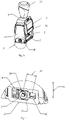
- Figures 1 to 5 show a first embodiment of a turning device 1.
- the turning device 1 is shown separately, ie as an incomplete self-inking stamp before individualization.
- the for individualization and Completion of the stamp usable components 2-4 are in 1 shown separately: an ink pad holder 2 with an ink pad, a turning axis 3 and an impression tool 4 in the form of a type unit (alternatively a text plate carrier with a text plate).
- the turning device 1 has a housing 5 , an actuating bracket 6 and a tool frame 7 .
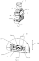
- the housing 5 On two opposite side walls 8, 9, the housing 5 has a cam 10, which is curved at least in sections, for a turning axis 3.
- the two cams 10 are designed as curved slots in the side walls 8, 9.
- a cover 11 and a mirror 12 are connected to the housing 5 , the cover 11 covering a slot 13 for the ink pad holder 2 and the mirror 12 .
- the cover 11 and the mirror 12 are pivotally snapped onto the housing.
- a frame plate 14 is pushed from below over the actual (inner) housing 5 .
- the frame sheet metal 14 covers the majority of the cams 10 on both sides towards the outside (cf. figure 5 ).
- a receiving space for the legs 15 of the actuating bracket 6 is kept free on both sides between the housing 5 and the frame sheet metal 14 and this counteracts collisions or jamming of objects.
- this On the upper side 16 of the housing 5, this has a vertical strut 17 and two through-slots 18 for the legs 15.
- turning pins 41 are provided on the inside of the side walls 8, 9, each of which is guided in a corresponding receptacle 19 in the tool frame 7 and, together with the cams 10, when the actuating bracket 6 moves between the impression position (cf. 3 ) and the stamp inking position (cf. figure 5 ) cause the turning of the tool frame 7 together with an impression tool 4 accommodated therein.
- Feet 40 are connected to the housing on an underside 39 of the housing 5 and fixed with snap connections.
- the feet 40 can serve as the end of an (optional) open cam 10 and have non-slip pads made of rubber.
- the first leg 40, on a first side 29, has an opening 42 for inserting and removing the turning axis 3, while the second leg 40 has no such opening.
- the actuating bracket 6 is guided through the through-slots 18 of the housing 5 and can be displaced relative to the housing (cf. 3 and 5 ).
- the outer edges of the legs 15 are linearly guided along and in each case between two parallel guide surfaces 20 in the housing 5 .
- the actuating bracket 6 has on each of the two legs 15 arranged parallel to the side walls 8, 9 of the housing 5 a guide 21 for a turning axis (cf. 4 ).
- the two guides 21 each have an elongated hole 22 which has a constant width in a working area 23 and a widened section 24 next to the working area 23 for the introduction of a sliding bush 25 when the turning device 1 is being manufactured.
- the working area 23 is that area within which the slide bushing 25 is displaced during operation of a stamp due to the course of the cams 10 .
- a slide bushing 25 is slidably mounted in each of the two slotted holes 22 , so that the slotted holes 22 are plain bearings for the slide bushings 25 .
- the slide bushings 25 each have a central cylindrical passage 26 which serves as a rotary slide bearing for a turning axis 3 .
- the slide bushings 25 On the outside, have a groove 27 at the top and bottom (relative to a use position of a punch), in which the edges of the elongated hole 22 are received, so that the elongated holes 22 in the working area 23 form linear guides for the slide bushings 25.
- the turning axis 3 is movably mounted in the guide 21 .
- the guide 21 is arranged essentially transversely to a displacement direction 28 or push-off direction of the actuating bracket 6 relative to the housing 5 .
- the guide 21 and the cam 10 overlap on both sides.
- the guide 21 elongated hole 22, slide bushing 25 and passage 26
- the control cam 10 form a continuous opening on a first side 29 that is accessible from an outside, so that a turning axis 3 in the longitudinal direction 30 can be inserted into or removed from the turning device 1 from the outside.
- the actuating bracket 6 is held by a spring element in the bar 17 (for the sake of simplicity, in 9 the spring element not shown) held in a stamp inking position and can against the spring force of the spring element in an imprint position be moved.
- the bar 17 In the push-off position, the bar 17 is accommodated in a handle 31 on the upper side of the actuating bracket.
- the two slide bushings 25 form (first) limiting elements in the form of widenings of the legs 15 so that the widenings cannot overcome the slots 18 in the housing 5 (as second limiting elements) through which the legs 15 are guided into the housing 5 .
- the slide bushings 25 hold a tool frame 7 for receiving an impression tool in the housing 5, in that projections 36 directed towards the interior of the housing are snapped into receptacles 37 provided for this purpose in the tool frame 7 and are connected thereto.
- the short side walls 38 of the tool frame 7 are temporarily pressed inwards.
- an impression tool 4 in the form of a type unit is accommodated in the tool frame 7 and a turning axis 3 runs through the turning device 1 (sliding bushings 25, control slots 10 and tool frame 7) and the impression tool 4.
- the alternative embodiment does not have a tool frame 7 . Accordingly, the sliding bushings 25 do without projections 36 .
- the impression tool 4 is thus held directly by the turning axis 3 .
- the turning pins 41 are guided directly in the impression tool 4 in corresponding receptacles 19 ′.
- the first bushing 25, on a first side 29, is continuous for the turning axis 3;
- the second bushing 25, on a second Page 32 has a stop 33 for a turning axis 3 introduced in the longitudinal direction 30 .
- the second slide bushing 25 has a connecting element 34 in the form of a snap hook for producing a snap connection with a turning axis 3 accommodated therein, more precisely an annular groove 35 in the turning axis 3 .
- the turning axis 3 is connected to the impression tool 4 via a snap connection 43 and is thus secured against movement in the longitudinal direction 30 of the turning axis 3 .
- the turning device is 1 in 11 shown without a type unit, but with an impression tool 4 in the form of a text plate carrier with a recess for a type unit.
Landscapes
- Manufacture Or Reproduction Of Printing Formes (AREA)
- Rotary Presses (AREA)
- Discharge By Other Means (AREA)
Claims (11)
- Dispositif de retournement (1) pour un tampon auto-encreur, comprenant un boîtier (5) et un étrier d'actionnement (6), où le boîtier (5) comporte sur deux parois latérales opposées (8, 9) à chaque fois une came de commande (10) incurvée au moins par sections pour un axe de retournement (3), où l'étrier d'actionnement (6) est relié au boîtier (5) et peut être déplacé par rapport au boîtier (5), où l'étrier d'actionnement (6) comporte, sur deux branches (15) disposées parallèlement aux parois latérales (8, 9) du boîtier (5), à chaque fois un guide (21) pour un axe de retournement (3), où le guide (21) est disposé transversalement à une direction de déplacement (28) de l'étrier d'actionnement (6) par rapport au boîtier (5), où le guide (21) et la came de commande (10) se recouvrent partiellement au moins sur un premier côté (29) et dans au moins une position de l'étrier d'actionnement (6) par rapport au boîtier (5) et forment une ouverture de passage depuis un côté externe, de sorte qu'un axe de retournement (3) peut être introduit depuis l'extérieur dans la direction longitudinale (30) dans le dispositif de retournement (1), où les guides (21) comportent chacun une douille de glissement (25) montée de manière déplaçable avec un palier pour un axe de retournement (3), caractérisé en ce que les guides des douilles de glissement montées de manière déplaçable sont des guides linéaires, qui bloquent à chaque fois un mouvement de la douille de glissement dans la direction d'un axe longitudinal d'un axe de retournement qui doit y être reçu, où un rebord du guide linéaire respectif s'engage dans une rainure parallèle dans la douille de glissement respective.
- Dispositif de retournement (1) selon la revendication 1, caractérisé en ce que le guide (21) ou la came de commande (10) comporte sur un deuxième côté (32) opposé au premier côté (29) une butée (33) pour un axe de retournement (3) introduit dans la direction longitudinale (30).
- Dispositif de retournement (1) selon la revendication 1 ou 2, caractérisé en ce qu'au moins l'un des guides (21) comporte un élément de liaison (34) pour la réalisation d'une liaison par encliquetage avec un axe de retournement (3) qui y est reçu.
- Dispositif de retournement (1) selon l'une des revendications 1 à 3, caractérisé en ce que l'étrier d'actionnement (6) comporte un premier élément de limitation, où le boîtier (5) comporte un deuxième élément de limitation correspondant, où les deux éléments de limitation sont disposés pour limiter un déplacement de l'étrier d'actionnement (6) et bloquent l'étrier d'actionnement (6) contre une séparation d'avec le boîtier (5).
- Dispositif de retournement (1) selon l'une des revendications 1 à 4, caractérisé en ce qu'au moins l'une des douilles de glissement (25) forme le premier élément de limitation.
- Dispositif de retournement (1) selon l'une des revendications 1 à 5, caractérisé en ce que les douilles de glissement (25) sont reliées à un cadre d'outil (7) pour recevoir un outil d'impression (4).
- Dispositif de retournement (1) selon la revendication 6, caractérisé en ce qu'au moins l'une des douilles de glissement (25) est reliée au cadre d'outil (7) par l'intermédiaire d'une liaison par encliquetage.
- Tampon auto-encreur avec un dispositif de retournement (1) selon l'une des revendications 1 à 7, avec un outil d'impression (4) reçu dans celui-ci et avec un axe de retournement (3) qui s'étend à travers le dispositif de retournement (1) et l'outil d'impression (4).
- Tampon auto-encreur selon la revendication 8, caractérisé en ce que l'axe de retournement (3) est relié à l'outil d'impression (4) par l'intermédiaire d'une liaison par encliquetage (43) et est fixé contre un mouvement dans la direction longitudinale (30) de l'axe de retournement (3).
- Procédé pour produire un tampon auto-encreur au moyen d'un dispositif de retournement (1) selon l'une des revendications 1 à 7, d'un outil d'impression (4) et d'un axe de retournement (3), comprenant:l'introduction de l'outil d'impression (4) dans le dispositif de retournement (1) depuis un côté inférieur (39);l'introduction de l'axe de retournement (3) suivant la direction longitudinale (30) de l'axe de retournement (3) depuis un premier côté (29) à travers le boîtier (5) et l'étrier d'actionnement (6), à travers l'outil d'impression (4) et jusqu'à un deuxième côté (32) du boîtier (5) et de l'étrier d'actionnement (6).
- Procédé selon la revendication 10 au moyen d'un dispositif de retournement (1) selon l'une des revendications 6 ou 7, caractérisé en ce que l'outil d'impression (4) est introduit dans le cadre d'outil (7).
Applications Claiming Priority (2)
| Application Number | Priority Date | Filing Date | Title |
|---|---|---|---|
| ATA50819/2018A AT521730A1 (de) | 2018-09-24 | 2018-09-24 | Wendevorrichtung |
| PCT/AT2019/060313 WO2020061602A1 (fr) | 2018-09-24 | 2019-09-24 | Dispositif de retournement |
Publications (2)
| Publication Number | Publication Date |
|---|---|
| EP3856531A1 EP3856531A1 (fr) | 2021-08-04 |
| EP3856531B1 true EP3856531B1 (fr) | 2022-04-20 |
Family
ID=68109070
Family Applications (1)
| Application Number | Title | Priority Date | Filing Date |
|---|---|---|---|
| EP19780137.6A Active EP3856531B1 (fr) | 2018-09-24 | 2019-09-24 | Dispositif de retournement pour un tampon auto-encreur |
Country Status (8)
| Country | Link |
|---|---|
| US (1) | US11247500B2 (fr) |
| EP (1) | EP3856531B1 (fr) |
| CN (1) | CN112752655B (fr) |
| AT (1) | AT521730A1 (fr) |
| BR (1) | BR112021005036A2 (fr) |
| ES (1) | ES2913132T3 (fr) |
| PL (1) | PL3856531T3 (fr) |
| WO (1) | WO2020061602A1 (fr) |
Families Citing this family (6)
| Publication number | Priority date | Publication date | Assignee | Title |
|---|---|---|---|---|
| AT524047B1 (de) | 2020-12-03 | 2022-02-15 | Trodat Gmbh | Stempel und Achselement für den Stempel |
| USD1035767S1 (en) | 2023-01-17 | 2024-07-16 | Colop Stempelerzeugung Skopek Gesellshaft M.B.H. & Co. Kg | Printer stamp |
| USD1035766S1 (en) | 2023-01-17 | 2024-07-16 | Colop Stempelerzeugung Skopek Gesellshaft M.B.H. & Co. Kg. | Printer stamp |
| AT526894B1 (de) | 2023-02-10 | 2025-03-15 | Colop Stempelerzeugung Skopek Gmbh & Co Kg | Selbstfärbestempel und Verfahren zur Entnahme einer Wendeachse aus einem Selbstfärbestempel |
| AT526963B1 (de) * | 2023-02-10 | 2025-03-15 | Colop Stempelerzeugung Skopek Gmbh & Co Kg | Selbstfärbestempel |
| AT527090B1 (de) * | 2023-04-14 | 2025-02-15 | Colop Stempelerzeugung Skopek Gmbh & Co Kg | Wendevorrichtung |
Family Cites Families (16)
| Publication number | Priority date | Publication date | Assignee | Title |
|---|---|---|---|---|
| US3099955A (en) * | 1961-05-16 | 1963-08-06 | Jack W Robbins | Type band setting means in hand stamps |
| AT286325B (de) | 1968-04-01 | 1970-12-10 | Just Trodat Werke | Selbstfärbestempel mit Oberschlagfärbung |
| US3714894A (en) * | 1970-12-03 | 1973-02-06 | G Robinson | Reciprocating handstamp with magnetic plate holding means for removing the plate |
| CA1037313A (fr) * | 1975-02-20 | 1978-08-29 | Alois Muller | Tampon a plaque amovible |
| AT379552B (de) * | 1984-07-26 | 1986-01-27 | Walter Just Gesellschaft M.B.H. | Selbstfaerbestempel mit oberschlagfaerbung |
| AT2996U1 (de) * | 1998-10-14 | 1999-08-25 | Colop Stempelerzeugung Skopek | Achssicherung für die schwenkachse eines handstempels sowie handstempel |
| AT501286B8 (de) * | 2005-01-25 | 2007-02-15 | Colop Stempelerzeugung Skopek | Einrichtung zur sicherung einer wendeachse eines typenaggregats |
| US7761959B2 (en) * | 2007-11-30 | 2010-07-27 | Shiny Shih | Handle assembly for a stamp |
| CN201506087U (zh) * | 2009-08-20 | 2010-06-16 | 上海吉普生办公用品有限公司 | 铰链式翻转印面回墨印章 |
| US8230782B2 (en) * | 2010-07-22 | 2012-07-31 | Warm Sun Enterprises Co., Ltd. | Stamp die assembly for a self-inking stamping device |
| CN103522777A (zh) | 2012-07-03 | 2014-01-22 | 上海豪普森生物识别应用科技有限公司 | 一种指纹印章的翻转机构 |
| CN203567385U (zh) | 2013-11-18 | 2014-04-30 | 上海吉普生办公用品有限公司 | 一种可更换印面的自动回墨印章 |
| CN203567386U (zh) * | 2013-11-28 | 2014-04-30 | 张家港市锦力标准件制造有限公司 | 一种用于连续冲压模的刻字模 |
| AT515227B1 (de) * | 2014-01-08 | 2024-10-15 | Colop Stempelerzeugung Skopek Gmbh & Co Kg | Selbstfärbestempel |
| AT517322A1 (de) * | 2015-06-10 | 2016-12-15 | Trodat Gmbh | Stempel und Abdruckeinheit, insbesondere als Ersatzteil für einen Stempel |
| CN204998164U (zh) * | 2015-09-18 | 2016-01-27 | 上海吉普生办公用品有限公司 | 一种活动印面的自动回墨印章 |
-
2018
- 2018-09-24 AT ATA50819/2018A patent/AT521730A1/de unknown
-
2019
- 2019-09-24 EP EP19780137.6A patent/EP3856531B1/fr active Active
- 2019-09-24 ES ES19780137T patent/ES2913132T3/es active Active
- 2019-09-24 US US17/278,710 patent/US11247500B2/en active Active
- 2019-09-24 BR BR112021005036-1A patent/BR112021005036A2/pt unknown
- 2019-09-24 PL PL19780137.6T patent/PL3856531T3/pl unknown
- 2019-09-24 WO PCT/AT2019/060313 patent/WO2020061602A1/fr not_active Ceased
- 2019-09-24 CN CN201980062537.1A patent/CN112752655B/zh active Active
Also Published As
| Publication number | Publication date |
|---|---|
| EP3856531A1 (fr) | 2021-08-04 |
| WO2020061602A1 (fr) | 2020-04-02 |
| BR112021005036A2 (pt) | 2021-06-08 |
| US11247500B2 (en) | 2022-02-15 |
| AT521730A1 (de) | 2020-04-15 |
| CN112752655B (zh) | 2022-03-18 |
| ES2913132T3 (es) | 2022-05-31 |
| US20210309033A1 (en) | 2021-10-07 |
| PL3856531T3 (pl) | 2022-12-27 |
| CN112752655A (zh) | 2021-05-04 |
Similar Documents
| Publication | Publication Date | Title |
|---|---|---|
| EP3856531B1 (fr) | Dispositif de retournement pour un tampon auto-encreur | |
| EP2591919B1 (fr) | Tampon | |
| EP1673229B1 (fr) | Tampon manuel a encrage automatique | |
| DE2800908C2 (de) | Sitzverstellvorrichtung für einen Fahrzeugsitz | |
| EP0258323B1 (fr) | Timbre comportant un dispositif encreur | |
| DE102014118141A1 (de) | Selbstfärbestempel | |
| DE60219354T2 (de) | Ic-kartenleser | |
| DE202015006833U1 (de) | Knochenstanze mit unverlierbarem Stanzschieber | |
| DE2646759C3 (de) | Vorrichtung zum Entnehmen und zum Transport von Kunststoff-Hohlkörpern einer Blasform | |
| EP3923767B1 (fr) | Tiroir | |
| DE2120161A1 (de) | Druckvorrichtung | |
| DE2809850C2 (de) | Teleskopartige Stützvorrichtung, insbesondere für Drehstühle | |
| DE2857558C2 (de) | Fahrzeugaußenspiegel | |
| DE3136192C2 (de) | Papierführung für Drucker | |
| DE10035427A1 (de) | Vorrichtung zum Eindrücken von Schrauben | |
| AT526894B1 (de) | Selbstfärbestempel und Verfahren zur Entnahme einer Wendeachse aus einem Selbstfärbestempel | |
| DE69913876T2 (de) | Einstellbare Befestigungsvorrichtung | |
| DE10354693B3 (de) | Vorrichtung zum Anzeigen einer Höhenstellung und/oder Gewichtsbelastung eines Fahrzeugsitzes | |
| AT527090B1 (de) | Wendevorrichtung | |
| EP3437814B1 (fr) | Perforatrice à papier | |
| DE19750683B4 (de) | Justiervorrichtung für die Antriebsverbindung eines Balkendiagramme aufzeichnenden Registrierorgans | |
| DE289376C (fr) | ||
| DE2526018A1 (de) | Gleitschienenfuehrung mit feststellvorrichtung fuer fahrzeugsitze | |
| DE3136872A1 (de) | Zeichenkopf fuer eine zeichenmaschine | |
| DE1816296A1 (de) | Umspurradsatz fuer Schienenfahrzeuge |
Legal Events
| Date | Code | Title | Description |
|---|---|---|---|
| STAA | Information on the status of an ep patent application or granted ep patent |
Free format text: STATUS: UNKNOWN |
|
| STAA | Information on the status of an ep patent application or granted ep patent |
Free format text: STATUS: THE INTERNATIONAL PUBLICATION HAS BEEN MADE |
|
| PUAI | Public reference made under article 153(3) epc to a published international application that has entered the european phase |
Free format text: ORIGINAL CODE: 0009012 |
|
| STAA | Information on the status of an ep patent application or granted ep patent |
Free format text: STATUS: REQUEST FOR EXAMINATION WAS MADE |
|
| 17P | Request for examination filed |
Effective date: 20210426 |
|
| AK | Designated contracting states |
Kind code of ref document: A1 Designated state(s): AL AT BE BG CH CY CZ DE DK EE ES FI FR GB GR HR HU IE IS IT LI LT LU LV MC MK MT NL NO PL PT RO RS SE SI SK SM TR |
|
| GRAP | Despatch of communication of intention to grant a patent |
Free format text: ORIGINAL CODE: EPIDOSNIGR1 |
|
| STAA | Information on the status of an ep patent application or granted ep patent |
Free format text: STATUS: GRANT OF PATENT IS INTENDED |
|
| DAV | Request for validation of the european patent (deleted) | ||
| DAX | Request for extension of the european patent (deleted) | ||
| INTG | Intention to grant announced |
Effective date: 20211215 |
|
| GRAS | Grant fee paid |
Free format text: ORIGINAL CODE: EPIDOSNIGR3 |
|
| GRAA | (expected) grant |
Free format text: ORIGINAL CODE: 0009210 |
|
| STAA | Information on the status of an ep patent application or granted ep patent |
Free format text: STATUS: THE PATENT HAS BEEN GRANTED |
|
| AK | Designated contracting states |
Kind code of ref document: B1 Designated state(s): AL AT BE BG CH CY CZ DE DK EE ES FI FR GB GR HR HU IE IS IT LI LT LU LV MC MK MT NL NO PL PT RO RS SE SI SK SM TR |
|
| REG | Reference to a national code |
Ref country code: GB Ref legal event code: FG4D Free format text: NOT ENGLISH |
|
| REG | Reference to a national code |
Ref country code: CH Ref legal event code: EP |
|
| REG | Reference to a national code |
Ref country code: DE Ref legal event code: R096 Ref document number: 502019004146 Country of ref document: DE |
|
| REG | Reference to a national code |
Ref country code: IE Ref legal event code: FG4D Free format text: LANGUAGE OF EP DOCUMENT: GERMAN |
|
| REG | Reference to a national code |
Ref country code: AT Ref legal event code: REF Ref document number: 1484891 Country of ref document: AT Kind code of ref document: T Effective date: 20220515 |
|
| REG | Reference to a national code |
Ref country code: ES Ref legal event code: FG2A Ref document number: 2913132 Country of ref document: ES Kind code of ref document: T3 Effective date: 20220531 |
|
| REG | Reference to a national code |
Ref country code: LT Ref legal event code: MG9D |
|
| REG | Reference to a national code |
Ref country code: NL Ref legal event code: MP Effective date: 20220420 |
|
| PG25 | Lapsed in a contracting state [announced via postgrant information from national office to epo] |
Ref country code: NL Free format text: LAPSE BECAUSE OF FAILURE TO SUBMIT A TRANSLATION OF THE DESCRIPTION OR TO PAY THE FEE WITHIN THE PRESCRIBED TIME-LIMIT Effective date: 20220420 |
|
| PG25 | Lapsed in a contracting state [announced via postgrant information from national office to epo] |
Ref country code: SE Free format text: LAPSE BECAUSE OF FAILURE TO SUBMIT A TRANSLATION OF THE DESCRIPTION OR TO PAY THE FEE WITHIN THE PRESCRIBED TIME-LIMIT Effective date: 20220420 Ref country code: PT Free format text: LAPSE BECAUSE OF FAILURE TO SUBMIT A TRANSLATION OF THE DESCRIPTION OR TO PAY THE FEE WITHIN THE PRESCRIBED TIME-LIMIT Effective date: 20220822 Ref country code: NO Free format text: LAPSE BECAUSE OF FAILURE TO SUBMIT A TRANSLATION OF THE DESCRIPTION OR TO PAY THE FEE WITHIN THE PRESCRIBED TIME-LIMIT Effective date: 20220720 Ref country code: LT Free format text: LAPSE BECAUSE OF FAILURE TO SUBMIT A TRANSLATION OF THE DESCRIPTION OR TO PAY THE FEE WITHIN THE PRESCRIBED TIME-LIMIT Effective date: 20220420 Ref country code: HR Free format text: LAPSE BECAUSE OF FAILURE TO SUBMIT A TRANSLATION OF THE DESCRIPTION OR TO PAY THE FEE WITHIN THE PRESCRIBED TIME-LIMIT Effective date: 20220420 Ref country code: GR Free format text: LAPSE BECAUSE OF FAILURE TO SUBMIT A TRANSLATION OF THE DESCRIPTION OR TO PAY THE FEE WITHIN THE PRESCRIBED TIME-LIMIT Effective date: 20220721 Ref country code: FI Free format text: LAPSE BECAUSE OF FAILURE TO SUBMIT A TRANSLATION OF THE DESCRIPTION OR TO PAY THE FEE WITHIN THE PRESCRIBED TIME-LIMIT Effective date: 20220420 Ref country code: BG Free format text: LAPSE BECAUSE OF FAILURE TO SUBMIT A TRANSLATION OF THE DESCRIPTION OR TO PAY THE FEE WITHIN THE PRESCRIBED TIME-LIMIT Effective date: 20220720 |
|
| PG25 | Lapsed in a contracting state [announced via postgrant information from national office to epo] |
Ref country code: RS Free format text: LAPSE BECAUSE OF FAILURE TO SUBMIT A TRANSLATION OF THE DESCRIPTION OR TO PAY THE FEE WITHIN THE PRESCRIBED TIME-LIMIT Effective date: 20220420 Ref country code: LV Free format text: LAPSE BECAUSE OF FAILURE TO SUBMIT A TRANSLATION OF THE DESCRIPTION OR TO PAY THE FEE WITHIN THE PRESCRIBED TIME-LIMIT Effective date: 20220420 Ref country code: IS Free format text: LAPSE BECAUSE OF FAILURE TO SUBMIT A TRANSLATION OF THE DESCRIPTION OR TO PAY THE FEE WITHIN THE PRESCRIBED TIME-LIMIT Effective date: 20220820 |
|
| REG | Reference to a national code |
Ref country code: DE Ref legal event code: R097 Ref document number: 502019004146 Country of ref document: DE |
|
| PG25 | Lapsed in a contracting state [announced via postgrant information from national office to epo] |
Ref country code: SM Free format text: LAPSE BECAUSE OF FAILURE TO SUBMIT A TRANSLATION OF THE DESCRIPTION OR TO PAY THE FEE WITHIN THE PRESCRIBED TIME-LIMIT Effective date: 20220420 Ref country code: SK Free format text: LAPSE BECAUSE OF FAILURE TO SUBMIT A TRANSLATION OF THE DESCRIPTION OR TO PAY THE FEE WITHIN THE PRESCRIBED TIME-LIMIT Effective date: 20220420 Ref country code: RO Free format text: LAPSE BECAUSE OF FAILURE TO SUBMIT A TRANSLATION OF THE DESCRIPTION OR TO PAY THE FEE WITHIN THE PRESCRIBED TIME-LIMIT Effective date: 20220420 Ref country code: EE Free format text: LAPSE BECAUSE OF FAILURE TO SUBMIT A TRANSLATION OF THE DESCRIPTION OR TO PAY THE FEE WITHIN THE PRESCRIBED TIME-LIMIT Effective date: 20220420 Ref country code: DK Free format text: LAPSE BECAUSE OF FAILURE TO SUBMIT A TRANSLATION OF THE DESCRIPTION OR TO PAY THE FEE WITHIN THE PRESCRIBED TIME-LIMIT Effective date: 20220420 Ref country code: CZ Free format text: LAPSE BECAUSE OF FAILURE TO SUBMIT A TRANSLATION OF THE DESCRIPTION OR TO PAY THE FEE WITHIN THE PRESCRIBED TIME-LIMIT Effective date: 20220420 |
|
| PLBE | No opposition filed within time limit |
Free format text: ORIGINAL CODE: 0009261 |
|
| STAA | Information on the status of an ep patent application or granted ep patent |
Free format text: STATUS: NO OPPOSITION FILED WITHIN TIME LIMIT |
|
| 26N | No opposition filed |
Effective date: 20230123 |
|
| PG25 | Lapsed in a contracting state [announced via postgrant information from national office to epo] |
Ref country code: AL Free format text: LAPSE BECAUSE OF FAILURE TO SUBMIT A TRANSLATION OF THE DESCRIPTION OR TO PAY THE FEE WITHIN THE PRESCRIBED TIME-LIMIT Effective date: 20220420 |
|
| PG25 | Lapsed in a contracting state [announced via postgrant information from national office to epo] |
Ref country code: MC Free format text: LAPSE BECAUSE OF FAILURE TO SUBMIT A TRANSLATION OF THE DESCRIPTION OR TO PAY THE FEE WITHIN THE PRESCRIBED TIME-LIMIT Effective date: 20220420 |
|
| REG | Reference to a national code |
Ref country code: CH Ref legal event code: PL |
|
| REG | Reference to a national code |
Ref country code: BE Ref legal event code: MM Effective date: 20220930 |
|
| P01 | Opt-out of the competence of the unified patent court (upc) registered |
Effective date: 20230517 |
|
| PG25 | Lapsed in a contracting state [announced via postgrant information from national office to epo] |
Ref country code: LU Free format text: LAPSE BECAUSE OF NON-PAYMENT OF DUE FEES Effective date: 20220924 |
|
| PG25 | Lapsed in a contracting state [announced via postgrant information from national office to epo] |
Ref country code: LI Free format text: LAPSE BECAUSE OF NON-PAYMENT OF DUE FEES Effective date: 20220930 Ref country code: IE Free format text: LAPSE BECAUSE OF NON-PAYMENT OF DUE FEES Effective date: 20220924 Ref country code: CH Free format text: LAPSE BECAUSE OF NON-PAYMENT OF DUE FEES Effective date: 20220930 |
|
| PG25 | Lapsed in a contracting state [announced via postgrant information from national office to epo] |
Ref country code: BE Free format text: LAPSE BECAUSE OF NON-PAYMENT OF DUE FEES Effective date: 20220930 |
|
| PG25 | Lapsed in a contracting state [announced via postgrant information from national office to epo] |
Ref country code: CY Free format text: LAPSE BECAUSE OF FAILURE TO SUBMIT A TRANSLATION OF THE DESCRIPTION OR TO PAY THE FEE WITHIN THE PRESCRIBED TIME-LIMIT Effective date: 20220420 |
|
| PG25 | Lapsed in a contracting state [announced via postgrant information from national office to epo] |
Ref country code: MK Free format text: LAPSE BECAUSE OF FAILURE TO SUBMIT A TRANSLATION OF THE DESCRIPTION OR TO PAY THE FEE WITHIN THE PRESCRIBED TIME-LIMIT Effective date: 20220420 Ref country code: HU Free format text: LAPSE BECAUSE OF FAILURE TO SUBMIT A TRANSLATION OF THE DESCRIPTION OR TO PAY THE FEE WITHIN THE PRESCRIBED TIME-LIMIT; INVALID AB INITIO Effective date: 20190924 |
|
| PG25 | Lapsed in a contracting state [announced via postgrant information from national office to epo] |
Ref country code: MT Free format text: LAPSE BECAUSE OF FAILURE TO SUBMIT A TRANSLATION OF THE DESCRIPTION OR TO PAY THE FEE WITHIN THE PRESCRIBED TIME-LIMIT Effective date: 20220420 |
|
| PG25 | Lapsed in a contracting state [announced via postgrant information from national office to epo] |
Ref country code: BG Free format text: LAPSE BECAUSE OF FAILURE TO SUBMIT A TRANSLATION OF THE DESCRIPTION OR TO PAY THE FEE WITHIN THE PRESCRIBED TIME-LIMIT Effective date: 20220420 |
|
| PG25 | Lapsed in a contracting state [announced via postgrant information from national office to epo] |
Ref country code: BG Free format text: LAPSE BECAUSE OF FAILURE TO SUBMIT A TRANSLATION OF THE DESCRIPTION OR TO PAY THE FEE WITHIN THE PRESCRIBED TIME-LIMIT Effective date: 20220420 |
|
| PGFP | Annual fee paid to national office [announced via postgrant information from national office to epo] |
Ref country code: DE Payment date: 20250919 Year of fee payment: 7 |
|
| PGFP | Annual fee paid to national office [announced via postgrant information from national office to epo] |
Ref country code: TR Payment date: 20250916 Year of fee payment: 7 Ref country code: PL Payment date: 20250812 Year of fee payment: 7 |
|
| PGFP | Annual fee paid to national office [announced via postgrant information from national office to epo] |
Ref country code: GB Payment date: 20250923 Year of fee payment: 7 |
|
| PGFP | Annual fee paid to national office [announced via postgrant information from national office to epo] |
Ref country code: FR Payment date: 20250924 Year of fee payment: 7 Ref country code: AT Payment date: 20250909 Year of fee payment: 7 |
|
| PGFP | Annual fee paid to national office [announced via postgrant information from national office to epo] |
Ref country code: IT Payment date: 20250930 Year of fee payment: 7 |
|
| PGFP | Annual fee paid to national office [announced via postgrant information from national office to epo] |
Ref country code: ES Payment date: 20251020 Year of fee payment: 7 |
|
| PG25 | Lapsed in a contracting state [announced via postgrant information from national office to epo] |
Ref country code: SI Free format text: LAPSE BECAUSE OF FAILURE TO SUBMIT A TRANSLATION OF THE DESCRIPTION OR TO PAY THE FEE WITHIN THE PRESCRIBED TIME-LIMIT Effective date: 20220420 |