EP3858128A1 - Automatischer mäher, verfahren und vorrichtung zum betrieb und zur steuerung desselben und elektronische vorrichtung - Google Patents
Automatischer mäher, verfahren und vorrichtung zum betrieb und zur steuerung desselben und elektronische vorrichtung Download PDFInfo
- Publication number
- EP3858128A1 EP3858128A1 EP19865310.7A EP19865310A EP3858128A1 EP 3858128 A1 EP3858128 A1 EP 3858128A1 EP 19865310 A EP19865310 A EP 19865310A EP 3858128 A1 EP3858128 A1 EP 3858128A1
- Authority
- EP
- European Patent Office
- Prior art keywords
- automatic mower
- cutting unit
- controlling
- working mode
- auxiliary cutting
- Prior art date
- Legal status (The legal status is an assumption and is not a legal conclusion. Google has not performed a legal analysis and makes no representation as to the accuracy of the status listed.)
- Granted
Links
Images


Classifications
-
- G—PHYSICS
- G05—CONTROLLING; REGULATING
- G05D—SYSTEMS FOR CONTROLLING OR REGULATING NON-ELECTRIC VARIABLES
- G05D1/00—Control of position, course, altitude or attitude of land, water, air or space vehicles, e.g. using automatic pilots
- G05D1/02—Control of position or course in two dimensions
- G05D1/021—Control of position or course in two dimensions specially adapted to land vehicles
- G05D1/0212—Control of position or course in two dimensions specially adapted to land vehicles with means for defining a desired trajectory
- G05D1/0214—Control of position or course in two dimensions specially adapted to land vehicles with means for defining a desired trajectory in accordance with safety or protection criteria, e.g. avoiding hazardous areas
-
- A—HUMAN NECESSITIES
- A01—AGRICULTURE; FORESTRY; ANIMAL HUSBANDRY; HUNTING; TRAPPING; FISHING
- A01D—HARVESTING; MOWING
- A01D34/00—Mowers; Mowing apparatus of harvesters
- A01D34/006—Control or measuring arrangements
- A01D34/008—Control or measuring arrangements for automated or remotely controlled operation
-
- A—HUMAN NECESSITIES
- A01—AGRICULTURE; FORESTRY; ANIMAL HUSBANDRY; HUNTING; TRAPPING; FISHING
- A01D—HARVESTING; MOWING
- A01D34/00—Mowers; Mowing apparatus of harvesters
- A01D34/835—Mowers; Mowing apparatus of harvesters specially adapted for particular purposes
- A01D34/84—Mowers; Mowing apparatus of harvesters specially adapted for particular purposes for edges of lawns or fields, e.g. for mowing close to trees or walls
-
- G—PHYSICS
- G05—CONTROLLING; REGULATING
- G05D—SYSTEMS FOR CONTROLLING OR REGULATING NON-ELECTRIC VARIABLES
- G05D1/00—Control of position, course, altitude or attitude of land, water, air or space vehicles, e.g. using automatic pilots
- G05D1/02—Control of position or course in two dimensions
- G05D1/021—Control of position or course in two dimensions specially adapted to land vehicles
- G05D1/0212—Control of position or course in two dimensions specially adapted to land vehicles with means for defining a desired trajectory
- G05D1/0219—Control of position or course in two dimensions specially adapted to land vehicles with means for defining a desired trajectory ensuring the processing of the whole working surface
-
- A—HUMAN NECESSITIES
- A01—AGRICULTURE; FORESTRY; ANIMAL HUSBANDRY; HUNTING; TRAPPING; FISHING
- A01D—HARVESTING; MOWING
- A01D2101/00—Lawn-mowers
Definitions
- the invention relates to an automatic mower, and in particular, to a method and apparatus for operating and controlling an automatic mower, an automatic mower including the apparatus for operating and controlling same, and an electronic device.
- Automatic mowers can automatically complete tasks such as lawn maintenance, and are increasingly popular with consumers.
- the automatic mower is restricted to working in a working area enclosed by the boundary.
- the existing automatic mower is provided with one or more cutter heads at a bottom of a machine body, a metal blade is mounted on the cutter head, and the cutter head rotates to form a cutting area. Since the blade on the cutter head of the mower rotates at a high speed, it may cause injury to people. Therefore, a high level of protection is required. As a result, the blade has a large protection distance and cannot cut the grass near the boundary, that is, the boundary cannot be completely trimmed.
- a technical problem of the existing automatic mower is: how to implement the complete trimming of the boundary while ensuring the safety of the mower.
- a problem to be solved by the present invention is to implement complete trimming of the boundary while ensuring safety of a mower.
- the determining whether the specific object is detected comprises:
- the determining whether the specific object is detected further comprises:
- the determining whether the specific object is detected comprises:
- the automatic mower performs at least one of:
- the changing a working state of the auxiliary cutting unit comprises at least one of:
- the changing a movement mode of the automatic mower comprises at least one of:
- the resuming the normal working mode of the auxiliary cutting unit based on at least the specific object being not detected comprises:
- the detecting the specific object is performed through at least one of: infrared sensing, image identification, ultrasonic/radar ranging, and depth imaging.
- An apparatus for operating and controlling an automatic mower the automatic mower comprises a main cutting unit and an auxiliary cutting unit, and the auxiliary cutting unit has a cutting range extending at least to be flush with a housing of the automatic mower, and wherein the apparatus comprises:
- the determining unit is configured to:
- the apparatus for operating and controlling an automatic mower the determining unit is further configured to detect a distance between the living body and the automatic mower; and the switching unit is further configured to switch the normal working mode to the obstacle working mode in response to the distance being less than a preset distance threshold.
- the apparatus for operating and controlling an automatic mower the determining unit is further configured to detect a relative speed between the living body and the automatic mower; and the switching unit is further configured to switch the normal working mode to the obstacle working mode in response to the relative speed being greater than a preset speed threshold.
- the apparatus for operating and controlling an automatic mower in the obstacle working mode, the automatic mower performs at least one of; changing a working state of the auxiliary cutting unit; changing a movement mode of the automatic mower; and warning.
- the changing a working state of the auxiliary cutting unit comprises at least one of: controlling the auxiliary cutting unit to stop working; and reducing a working speed of the auxiliary cutting unit.
- the changing a movement mode of the automatic mower comprises at least one of: controlling the automatic mower to stop moving; controlling the automatic mower to move back to keep away from the specific object; and controlling the automatic mower to make a turn to keep away from the specific object.
- the detection unit is further configured to detect the specific object in the obstacle working mode; the determining unit is further configured to determine whether the specific object is detected; the maintaining unit is further configured to maintain the obstacle working mode based on at least the specific object being detected; and the switching unit is further configured to resume the normal working mode of the auxiliary cutting unit based on at least the specific object being not detected.
- the apparatus for operating and controlling an automatic mower the detecting the specific object is performed through at least one of: infrared sensing, image identification, ultrasonic/radar ranging, and depth imaging.
- the detection unit is further configured to detect an ambient temperature of the automatic mower; and the maintaining unit is further configured to allow the auxiliary cutting unit to work in response to the ambient temperature being within a preset temperature range.
- the detection unit is further configured to detect an ambient illuminance of the automatic mower; and the switching unit is further configured to, control the auxiliary cutting unit to enter the normal working mode in response to the ambient illuminance being less than an illuminance threshold.
- An automatic mower comprising: a housing; a main cutting unit; an auxiliary cutting unit, wherein the auxiliary cutting unit has a cutting range extending at least to be flush with the housing of the automatic mower; in the above, the apparatus for operating and controlling an automatic mower, configured to control the normal working mode or the obstacle working mode of the auxiliary cutting unit.
- An electronic device comprising: a memory configured to store computer executable instructions; and a processor configured to execute the computer executable instructions stored in the memory to perform the method for operating and controlling an automatic mower.
- the beneficial effects of the present invention are as follows.
- the working of an automatic mower provided with an auxiliary cutting unit the complete trimming of the boundary can be achieved while ensuring the safety of the mower.
- FIG. 1 is a schematic diagram of an automatic working system 100 according to a first embodiment of the present invention.
- the automatic working system 100 includes an automatic mower 1.
- the above automatic working system 100 further includes a charging station 2 for supplying electric energy to the automatic mower 1.
- the automatic mower 1 is configured to work in a predetermined working area.
- the structure of the automatic mower 1 in this embodiment is shown in FIG. 2 .
- the automatic mower 1 includes a housing 3, a mobile module, a task execution module, an energy module, a control module, and the like.
- the mobile module includes a wheel set 5 driven by a driving motor to drive the automatic mower 1 to move.
- the task execution module includes a cutting assembly 7 that performs mowing.
- the energy module includes a battery pack (not shown in the figure), which provides electric energy for movement and working of the automatic mower 1.
- the control module is electrically connected to the mobile module, the task execution module, and the energy module to control the mobile module to drive the automatic mower 1 to move and control the task execution module to execute tasks.
- the automatic mower of the present invention further includes an auxiliary cutting unit for trimming in addition to the main cutting unit in the cutting assembly 7 as shown in FIG. 2 .
- the auxiliary cutting unit has a cutting range extending at least to be flush with the housing of the automatic mower, for example, the housing 3 shown in FIG. 2 .
- the auxiliary cutting unit of the automatic mower of the present invention may be a mowing head that includes a winder, a trimmer line wound around the winder, and a driving motor that drives the winder to rotate.
- a cutting element of the auxiliary cutting unit may be a flexible material, for example, a trimmer line, or may be a non-cutting metal material.
- cutting energy of the auxiliary cutting unit is preferably less than 2 joules.
- the auxiliary cutting unit may also be pruning shears, or the like.
- the auxiliary cutting unit When the auxiliary cutting unit is actually disposed, the auxiliary is usually disposed at an edge position of the housing due to use of trimming, and a positional relationship of the auxiliary cutting unit relative to the main cutting unit may have a plurality of examples.
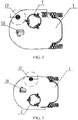
- FIG. 3 is a schematic diagram of a first arrangement example of a main cutting unit and an auxiliary cutting unit of the automatic mower of the present invention.
- the main cutting unit 7 is arranged in the middle of the whole machine of the automatic mower, and the auxiliary cutting unit 17 is arranged on a side of the middle of the automatic mower.
- an auxiliary cutting area of the auxiliary cutting unit 17 and a main cutting area of the main cutting unit 7 are tangent or overlap in a width direction of the automatic mower (that is, a direction perpendicular to a walking direction of the automatic mower) to prevent missing cuts.
- a universal wheel 19 is provided on a front side of the automatic mower, and in order not to hinder the working of the auxiliary cutting unit, a gap between the cutting area of the auxiliary cutting unit 17 and a movement area of the universal wheel 19 is greater than 5 mm.
- FIG. 4 is a schematic diagram of a second arrangement example of the main cutting unit and the auxiliary cutting unit of the automatic mower of the present invention.
- the auxiliary cutting unit 17 is arranged on the front end of the automatic mower and on the same side of the main cutting unit 7.
- the auxiliary cutting area of the auxiliary cutting unit and the main cutting area of the main cutting unit are tangent or overlap in a width direction of the automatic mower (that is, a direction perpendicular to the walking direction of the automatic mower), and the gap between the cutting area of the auxiliary cutting unit 17 and the movement area of the universal wheel 19 of the automatic mower is greater than 5 mm.
- FIG. 5 is a schematic diagram of a third arrangement example of the main cutting unit and the auxiliary cutting unit of the automatic mower of the present invention.
- the auxiliary cutting unit 17 is arranged on the front end of the automatic mower and on an opposite side of the main cutting unit 7.
- the automatic mower moves clockwise along a boundary of the working area to form a first moving path, and moves counter clockwise along the boundary of the working area to form a second moving path.
- the auxiliary cutting area in which the auxiliary cutting unit works when the automatic mower moves along the first moving path is tangent to or overlaps the main cutting area in which the main cutting unit works when the automatic mower moves along the second moving path.
- the gap between the cutting area of the auxiliary cutting unit 17 and the movement area of the universal wheel 19 of the automatic mower is greater than 5 mm.
- the auxiliary cutting unit is used for trimming, and the cutting energy of the auxiliary cutting unit is preferably limited to avoid causing harm to other objects or the human body, these injuries still cannot be completely avoided, especially for the human body, and it is necessary to completely prevent the auxiliary cutting unit from touching the human body as far as possible.
- the auxiliary cutting unit touches other hard objects during cutting, it may also cause damage to the auxiliary cutting unit itself.
- the present invention further provides a method for operating and controlling the above automatic mower provided with the auxiliary cutting unit.
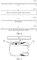
- FIG. 6 is a schematic flowchart of a method for operating and controlling an automatic mower of the present invention.
- the automatic mower includes a main cutting unit and an auxiliary cutting unit for trimming, and the auxiliary cutting unit has a cutting range extending at least to be flush with a housing of the automatic mower or to exceed the housing.
- the method for operating and controlling an automatic mower includes: S510: Detect a specific object in a normal working mode of the auxiliary cutting unit; S520: Determine whether the specific object is detected; S530: Switch to an obstacle working mode based on at least the specific object being detected; and S540: Maintain the normal working mode of the auxiliary cutting unit based on at least the specific object being not detected.
- step S510 the detection of the specific object is performed in the normal working mode of the auxiliary cutting unit.
- the normal working mode of the auxiliary cutting unit refers to a working mode in which the auxiliary cutting unit normally performs trimming operations. Moreover, since the auxiliary cutting unit has a cutting range extending at least to be flush with the housing of the automatic mower during the trimming operation, it is necessary to detect a specific object, to prevent the auxiliary cutting unit from damaging the specific object or the auxiliary cutting unit from being damaged by the specific object.
- the specific object may be a living body such as a person or an animal, or other objects that are moving and may affect the working of the automatic mower, for example, objects that move at a speed greater than a predetermined threshold.
- living body in the embodiments of the present invention not only refers to living objects, but also refers to other moving objects to be distinguished from fixed obstacles in the working environment of the automatic mower.
- step S520 it is determined whether the specific object is detected.
- the determining whether the specific object is detected includes: determining whether a detected object is a living body; and determining that the specific object is detected in response to the detected object being the living body.
- a distance between the living body and the automatic mower may be further determined in response to the object being the living body, thereby further determining whether the living body interacts with the automatic mower to reduce a misoperation rate of the automatic mower.
- the determining whether the specific object is detected further includes: detecting the distance between the living body and the automatic mower; and the switching to an obstacle working mode based on the specific object being detected includes: switching the normal working mode to the obstacle working mode in response to the distance being less than a preset distance threshold.
- the determining whether the specific object is detected includes: detecting a relative speed between the living body and the automatic mower; and the switching to the obstacle working mode based on at least the specific object being detected includes: switching the normal working mode to the obstacle working mode in response to the relative speed being greater than a preset speed threshold.
- step S530 the normal working mode is switched to the obstacle working mode based on at least the specific object being detected.
- the working mode of the auxiliary cutting unit needs to be changed.
- the automatic mower in the obstacle working mode of the auxiliary cutting unit, performs at least one of: changing a working status of the auxiliary cutting unit; changing a movement mode of the automatic mower; and warning.
- the automatic mower may stop the working of the auxiliary cutting unit or reduce the cutting speed of the auxiliary cutting unit, or lower the cutting energy of the auxiliary cutting unit.
- the automatic mower can move through making a turn, avoidance, or the like to avoid damage.
- the automatic mower may remind a user of the occurrence of an unforeseen circumstance by giving a warning, for example, transmit an alarm signal on the machine or transmit a warning message to a mobile phone of the user.
- step S540 the normal working mode of the auxiliary cutting unit is maintained based on at least the specific object being not detected. In other words, when the specific object is not detected, the main cutting unit is unlikely to cause damage to an external object or be damaged by the external object, so that the working status of the auxiliary cutting unit can be maintained.
- the method for operating and controlling an automatic mower further includes: detecting the specific object in the obstacle working mode; determining whether the specific object is detected; maintaining the obstacle working mode based on at least the specific object being detected; and resuming the normal working mode of the auxiliary cutting unit based on at least the specific object being not detected.
- the obstacle working mode it may continue to be detected whether the specific object that affects the working of the auxiliary cutting unit exists. If the specific object still exists, the obstacle working mode is maintained, and if the specific object does not exist, the normal working of the auxiliary cutting unit may be resumed.
- the resuming the normal working mode of the auxiliary cutting unit based on at least the specific object being not detected includes: resuming the normal working mode of the auxiliary cutting unit based on at least a working speed of the auxiliary cutting unit being not 0; and/or detecting whether a maintaining time of the obstacle working mode exceeds a preset safety time, and resuming the normal working mode of the auxiliary cutting unit based on at least the maintaining time not exceeding the preset safety time.
- the preset safety threshold is a value set according to safety regulations.
- the working speed of the auxiliary cutting unit is zero, that is, the auxiliary cutting unit stops working, the existence of the specific object is continuously detected.
- a time period for which the auxiliary cutting unit is in the obstacle working mode is determined.
- the automatic mower can receive an instruction of the user to resume the normal working mode.
- the preset time threshold is set according to the safety regulation.
- the preset time threshold is 10 s.
- that the automatic mower receives the instruction of the user to resume the normal working mode includes: restarting, by the user, the intelligent mower, so that the auxiliary cutting unit is resumed to the normal working mode; or resuming, by the user, the normal working mode of the auxiliary cutting unit through remote operations by using a device such as a mobile phone, an iPad, and the like.
- the auxiliary cutting unit continuously detects the existence of the specific object.
- the preset time threshold is set according to the safety regulation.
- the preset time threshold is 10 s.
- the detecting the specific object is performed through at least one of: infrared sensing, image identification, ultrasonic/radar ranging, and depth imaging.
- an infrared sensor may be used to identify whether a person is close to the automatic mower, so that the auxiliary cutting unit can be switched from the normal working mode to the obstacle working mode within a certain range of the distance between the person and the machine.
- the image identification technology it may be identified whether a person or a part of the human body is close to the automatic mower, and when the person or a part of the human body is within a certain range from the automatic mower, the auxiliary cutting unit is switched from the normal working mode to the obstacle working mode.
- the ultrasonic/radar ranging technology is used to identify the distance and an approaching speed between a moving object (including a person or an object) and a device.
- a moving object including a person or an object
- the auxiliary cutting unit is switched from the normal working mode to the obstacle working mode.
- the depth imaging technology may be used to perform three-dimensional imaging on the surroundings to identify the human body or the part of the human body.
- the auxiliary cutting unit is switched from the normal working mode to the obstacle working mode.
- the method for operating and controlling an automatic mower according to the embodiment of the present invention may also comprehensively utilize the above two or more technologies to control the working state of the automatic mower by identifying an approaching degree between a person or a moving object and the automatic mower, for example, the approaching distance and the approaching speed.
- FIG. 7 is a schematic diagram of sensor disposing of the automatic mower of the present invention.
- two or more sensors 21 for example, the sensor for infrared sensing, image identification, ultrasonic/radar ranging, and depth imaging
- the sensor for infrared sensing, image identification, ultrasonic/radar ranging, and depth imaging may be disposed on a side where the auxiliary cutting unit of the automatic mower is arranged.
- FIG. 8 by disposing a sensor with more than two channels, it may be ensured that the sensor does not miss detection.
- the automatic mower may be provided with a temperature sensor to be set to switch the working mode of the auxiliary cutting unit when it is detected that the ambient temperature is close to the human body temperature, to prevent erroneous determination.
- the automatic mower may be provided with a light sensor to be set to start the auxiliary cutting unit of the automatic mower to normally work after an illuminance is less than a set value, for example, to start the normal working mode at night, to prevent the light from affecting other sensors, such as detection accuracy of the infrared sensor.
- the method for operating and controlling an automatic mower further includes: detecting an ambient temperature of the automatic mower; and allowing the auxiliary cutting unit to work in response to the ambient temperature being within a preset temperature range.
- the method for operating and controlling an automatic mower further includes: detecting an ambient illuminance of the automatic mower; and controlling the auxiliary cutting unit to enter the normal working mode in response to the ambient illuminance being less than an illuminance threshold.
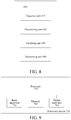
- FIG. 8 is a schematic block diagram of the apparatus for operating and controlling an automatic mower of the present invention.
- the apparatus 600 for operating and controlling an automatic mower shown in FIG. 8 is applied to the automatic mower having a main cutting unit and an auxiliary cutting unit for trimming as described above, and the auxiliary cutting unit has a cutting range extending at least to be flush with a housing of the automatic mower.
- the apparatus 600 for operating and controlling an automatic mower includes: a detection unit 610 configured to detect a specific object in a normal working mode of the auxiliary cutting unit; a determining unit 620 configured to determine whether the specific object is detected; a switching unit 630 configured to switch to an obstacle working mode based on at least the specific object being detected; and a maintaining unit 640 configured to maintain the normal working mode of the auxiliary cutting unit based on at least the specific object being not detected.
- the determining unit 620 is configured to: determine whether a detected object is a living body; and determine that the specific object is detected in response to the detected object being the living body.
- the determining unit 620 is further configured to detect a distance between the living body and the automatic mower; and the switching unit 630 is further configured to switch the normal working mode to the obstacle working mode in response to the distance being less than a preset distance threshold.
- the determining unit 620 is further configured to detect a relative speed between the living body and the automatic mower; and the switching unit 630 is further configured to switch the normal working mode to the obstacle working mode in response to the relative speed being greater than a preset speed threshold.
- the automatic mower in the obstacle working mode, performs at least one of: stopping the working of the auxiliary cutting unit; and changing a movement mode of the automatic mower.
- the detection unit 610 is further configured to detect the specific object in the obstacle working mode; the determining unit 620 is further configured to determine whether the specific object is detected; the maintaining unit 640 is further configured to maintain the obstacle working mode based on at least the specific object being detected; and the switching unit 630 is further configured to resume the normal working mode of the auxiliary cutting unit based on at least the specific object being not detected.
- the detecting the specific object is performed through at least one of: infrared sensing, image identification, ultrasonic/radar ranging, and depth imaging.
- the detection unit 610 is further configured to detect an ambient temperature of the automatic mower; and the maintaining unit 640 is further configured to allow the auxiliary cutting unit to work in response to the ambient temperature being within a preset temperature range.
- the detection unit 610 is further configured to detect an ambient illuminance of the automatic mower; and the switching unit 630 is further configured to control the auxiliary cutting unit to enter the normal working mode in response to the ambient illuminance being less than an illuminance threshold.
- the present invention further relates to an automatic mower, including: a housing; a main cutting unit; an auxiliary cutting unit for trimming, where the auxiliary cutting unit has a cutting range extending at least to be flush with the housing of the automatic mower; and the above apparatus for operating and controlling an automatic mower configured to control a normal working mode or an obstacle working mode of the auxiliary cutting unit.
- the beneficial effects of the present invention are as follows.
- the complete trimming of the boundary can be achieved while ensuring the safety of the mower.
- the electronic device may be an electronic device integrated in a mobile station of the automatic mower or a stand-alone device independent of the mobile station.
- the stand-alone device may communicate with the mobile station to implement the method for operating and controlling an automatic mower according to the present invention.
- FIG. 9 is a schematic block diagram of an electronic device of the present invention.
- the electronic device 700 includes one or more processors 710 and a memory 720.
- the processor 710 may be a central processing unit (CPU) or another form of processing unit with data processing capabilities and/or instruction execution capabilities, and may control other components in the electronic device 700 to perform desired functions.
- CPU central processing unit
- the processor 710 may control other components in the electronic device 700 to perform desired functions.
- the memory 720 may include one or more computer program products, and the computer program products may include various forms of computer-readable storage media, for example, a volatile memory and/or a non-volatile memory.
- the volatile memory may include a RAM and/or a cache.
- the non-volatile memory may include a ROM, a hard disk, or a flash memory.
- One or more computer program instructions may be stored on the computer-readable storage medium, and the processor 710 can run the program instructions to implement the method for operating and controlling the automatic mower of the various embodiments of the present invention described above and/or other desired functions.
- the computer-readable storage medium may also store various contents such as detection results of specific objects, working mode data, and the like.
- the electronic device 700 may further include: an input apparatus 730 and an output apparatus 740. These components are interconnected by a bus system and/or other forms of connection mechanisms (not shown).
- the input apparatus 730 may be configured to receive user inputs.
- the output apparatus 740 may directly output various information to the outside, or control the mobile station to transmit signals.
- FIG. 9 merely shows some of the components related to this application in the electronic device 700, and omits the components such as the bus, input/output interfaces, and the like.
- the electronic device 700 may also include any other appropriate components according to specific application conditions.
- the embodiments of this application may also be computer program products, which include computer program instructions which, when run by a processor, cause the processor to perform the steps in the method for operating and controlling an automatic mower according to various embodiments of the present invention described in the part of the "exemplary method for operating and controlling" in this specification.
- the computer program product may use one or more programming languages or a combination thereof to write the program code used for executing the operations of this application.
- the programming languages include an object-oriented programming language such as Java, C++ and the like, and also include a conventional procedural programming language such as "C" or similar programming languages.
- the program code may be completely executed on a user computing device, partially executed on a user device, executed as an independent software package, partially executed on a user computing device and partially executed on a remote computing device, or completely executed on a remote computing device or server.
- the embodiment of this application may also be a computer-readable storage medium having stored thereon computer program instructions which, when run by a processor, cause the processor to perform the steps in the method for operating and controlling an automatic mower according to various embodiments of the present invention described in the part of the "exemplary method for operating and controlling" in this specification.
- the computer-readable storage medium may use any combination of one or more readable media.
- the readable medium may be a computer-readable signal medium or a computer-readable storage medium.
- the readable storage medium may include, for example, but is not limited to, an electric, magnetic, optical, electromagnetic, infrared, or semiconductive system, apparatus, or device, or any combination thereof. More specific examples of the readable storage medium (a non-exhaustive list) include: an electrical connection having one or more wires, a portable disk, a hard disk, a RAM, a ROM, an erasable programmable ROM (EPROM or a flash memory), an optical fiber, a compact disc ROM (CD-ROM), an optical storage device, a magnetic storage device, or any appropriate combination thereof.
Landscapes
- Engineering & Computer Science (AREA)
- Life Sciences & Earth Sciences (AREA)
- Environmental Sciences (AREA)
- Aviation & Aerospace Engineering (AREA)
- Radar, Positioning & Navigation (AREA)
- Remote Sensing (AREA)
- Physics & Mathematics (AREA)
- General Physics & Mathematics (AREA)
- Automation & Control Theory (AREA)
- Harvester Elements (AREA)
- Control Of Position, Course, Altitude, Or Attitude Of Moving Bodies (AREA)
Priority Applications (1)
| Application Number | Priority Date | Filing Date | Title |
|---|---|---|---|
| EP24198068.9A EP4449846A3 (de) | 2018-09-27 | 2019-09-27 | Automatischer mäher, verfahren und vorrichtung zum betrieb und zur steuerung desselben und elektronische vorrichtung |
Applications Claiming Priority (2)
| Application Number | Priority Date | Filing Date | Title |
|---|---|---|---|
| CN201811132158.9A CN110945997A (zh) | 2018-09-27 | 2018-09-27 | 自动割草机及其操作控制方法、装置和电子设备 |
| PCT/CN2019/108416 WO2020063822A1 (zh) | 2018-09-27 | 2019-09-27 | 自动割草机及其操作控制方法、装置和电子设备 |
Related Child Applications (1)
| Application Number | Title | Priority Date | Filing Date |
|---|---|---|---|
| EP24198068.9A Division EP4449846A3 (de) | 2018-09-27 | 2019-09-27 | Automatischer mäher, verfahren und vorrichtung zum betrieb und zur steuerung desselben und elektronische vorrichtung |
Publications (3)
| Publication Number | Publication Date |
|---|---|
| EP3858128A1 true EP3858128A1 (de) | 2021-08-04 |
| EP3858128A4 EP3858128A4 (de) | 2022-06-22 |
| EP3858128B1 EP3858128B1 (de) | 2024-09-04 |
Family
ID=69949921
Family Applications (2)
| Application Number | Title | Priority Date | Filing Date |
|---|---|---|---|
| EP19865310.7A Active EP3858128B1 (de) | 2018-09-27 | 2019-09-27 | Automatischer mäher, verfahren und vorrichtung zum betrieb und zur steuerung desselben und elektronische vorrichtung |
| EP24198068.9A Pending EP4449846A3 (de) | 2018-09-27 | 2019-09-27 | Automatischer mäher, verfahren und vorrichtung zum betrieb und zur steuerung desselben und elektronische vorrichtung |
Family Applications After (1)
| Application Number | Title | Priority Date | Filing Date |
|---|---|---|---|
| EP24198068.9A Pending EP4449846A3 (de) | 2018-09-27 | 2019-09-27 | Automatischer mäher, verfahren und vorrichtung zum betrieb und zur steuerung desselben und elektronische vorrichtung |
Country Status (5)
| Country | Link |
|---|---|
| US (1) | US20210345545A1 (de) |
| EP (2) | EP3858128B1 (de) |
| CN (2) | CN110945997A (de) |
| DE (1) | DE202019006116U1 (de) |
| WO (1) | WO2020063822A1 (de) |
Families Citing this family (17)
| Publication number | Priority date | Publication date | Assignee | Title |
|---|---|---|---|---|
| IT201800009580A1 (it) * | 2018-10-18 | 2020-04-18 | Mdb Srl Con Socio Unico | Tagliaerba radiocomandato |
| KR102877692B1 (ko) * | 2019-09-04 | 2025-10-30 | 엘지전자 주식회사 | 이동 로봇 및 그의 구동 방법 |
| EP4057793A1 (de) * | 2019-11-13 | 2022-09-21 | The Toro Company | Roboter, der mehrere betriebsarten aufweist |
| JP2021153536A (ja) * | 2020-03-30 | 2021-10-07 | 本田技研工業株式会社 | 草刈り機 |
| WO2022117001A1 (zh) * | 2020-12-01 | 2022-06-09 | 苏州宝时得电动工具有限公司 | 移动机器人智能避障方法及移动机器人 |
| US12296694B2 (en) | 2021-03-10 | 2025-05-13 | Techtronic Cordless Gp | Lawnmowers |
| SE546711C2 (en) * | 2021-05-28 | 2025-02-11 | Husqvarna Ab | A robotic lawn mower with enhanced cutting properties |
| CN113778084A (zh) * | 2021-08-30 | 2021-12-10 | 普达迪泰(天津)智能装备科技有限公司 | 一种基于多光谱检测的复杂草地环境智能避障系统 |
| US12443180B2 (en) | 2021-11-10 | 2025-10-14 | Techtronic Cordless Gp | Robotic lawn mowers |
| AU2023200381A1 (en) | 2022-01-31 | 2023-08-17 | Techtronic Cordless Gp | Robotic garden tool |
| EP4270138A1 (de) | 2022-04-28 | 2023-11-01 | Techtronic Cordless GP | Erzeugung einer virtuellen grenze für ein robotisches gartenwerkzeug |
| US12472611B2 (en) | 2022-05-31 | 2025-11-18 | Techtronic Cordless Gp | Peg driver |
| EP4310621B1 (de) | 2022-07-19 | 2025-02-12 | Techtronic Cordless GP | Anzeige zur steuerung eines robotischen werkzeugs |
| AU2023206123A1 (en) | 2022-07-29 | 2024-02-15 | Techtronic Cordless Gp | Generation of a cryptography key for a robotic garden tool |
| CN116018924B (zh) * | 2022-12-07 | 2024-12-03 | 深圳拓邦股份有限公司 | 割草机的割草方法、装置和计算机设备 |
| CN119096790A (zh) * | 2024-10-17 | 2024-12-10 | 追觅科技(苏州)有限公司 | 一种割草机及其控制方法 |
| CN120540324B (zh) * | 2025-07-18 | 2025-11-25 | 追觅创新科技(苏州)有限公司 | 割草控制方法、智能割草机器人、程序产品和存储介质 |
Family Cites Families (33)
| Publication number | Priority date | Publication date | Assignee | Title |
|---|---|---|---|---|
| US5048615A (en) * | 1990-02-07 | 1991-09-17 | Feldmann Marvin H | Weed and grass trimmer |
| JP2008242908A (ja) * | 2007-03-28 | 2008-10-09 | Matsushita Electric Ind Co Ltd | 自律走行装置およびこの装置を機能させるためのプログラム |
| ITFI20070116A1 (it) * | 2007-05-17 | 2008-11-18 | Fabrizio Bernini | Tagliaerba |
| US8666550B2 (en) * | 2010-01-05 | 2014-03-04 | Deere & Company | Autonomous cutting element for sculpting grass |
| EP2547193B1 (de) * | 2010-03-18 | 2017-03-01 | Husqvarna AB | Robotischer rasenmäher mit kantenschnitt |
| CN106171248A (zh) * | 2012-08-31 | 2016-12-07 | 苏州宝时得电动工具有限公司 | 智能割草机及其控制方法 |
| CN103407491B (zh) * | 2013-04-28 | 2015-09-30 | 常雪阳 | 一种智能汽车及其控制方法 |
| CN104704980A (zh) * | 2013-12-12 | 2015-06-17 | 苏州宝时得电动工具有限公司 | 一种自动割草机 |
| CN103733801B (zh) * | 2014-01-02 | 2015-10-07 | 上海大学 | 一种组合式智能割草机器人 |
| CN204613789U (zh) * | 2015-03-10 | 2015-09-02 | 浙江理工大学 | 一种基于智能割草机的智能无线监控系统 |
| CN109757189A (zh) * | 2015-04-02 | 2019-05-17 | 苏州宝时得电动工具有限公司 | 智能割草机及其控制方法 |
| CN106142104B (zh) * | 2015-04-10 | 2019-01-22 | 科沃斯机器人股份有限公司 | 自移动机器人及其控制方法 |
| CN205082290U (zh) * | 2015-09-22 | 2016-03-16 | 天津奥克森重型机床有限公司 | 一种绿化修剪多功能机器人 |
| CN105182979B (zh) * | 2015-09-23 | 2018-02-23 | 上海物景智能科技有限公司 | 一种移动机器人障碍物检测及避让方法和系统 |
| CN106717479B (zh) * | 2015-11-20 | 2020-10-23 | 苏州宝时得电动工具有限公司 | 割草机 |
| DE202016009226U1 (de) * | 2015-10-13 | 2025-01-03 | Positec Technology (China) Co., Ltd. | Mäher |
| CN205596609U (zh) * | 2015-10-22 | 2016-09-28 | 湖北智权专利技术应用开发有限公司 | 一种可视全地形割草机器人 |
| CN107024928B (zh) * | 2016-02-01 | 2020-04-28 | 松下家电研究开发(杭州)有限公司 | 一种智能扫地机器人及智能扫地机器人控制方法 |
| CN205694290U (zh) * | 2016-04-12 | 2016-11-23 | 苏州宝时得电动工具有限公司 | 割草机 |
| US10051786B2 (en) * | 2016-07-13 | 2018-08-21 | Excel Industries, Inc. | Stand-on mower with winged deck |
| CN106249739A (zh) * | 2016-08-26 | 2016-12-21 | 广州小瓦智能科技有限公司 | 一种高性能机器人防撞移动算法 |
| IT201600089384A1 (it) * | 2016-09-02 | 2018-03-02 | Fabrizio Bernini | Robot tagliaerba e metodo per la selezione di un metodo di taglio di un robot tagliaerba |
| US20180077861A1 (en) * | 2016-09-21 | 2018-03-22 | Jerry Lego | Lawn Trimmer Assembly |
| EP3298874B1 (de) * | 2016-09-22 | 2020-07-01 | Honda Research Institute Europe GmbH | Robotergartenarbeitsvorrichtung und verfahren zur steuerung davon |
| IT201600116383A1 (it) * | 2016-11-17 | 2018-05-17 | Fabrizio Bernini | Robot tagliaerba automatico e metodo di controllo associato |
| CN106775895A (zh) * | 2017-01-09 | 2017-05-31 | 广东小天才科技有限公司 | 一种智能设备提醒方法及装置 |
| US10040450B1 (en) * | 2017-03-13 | 2018-08-07 | Wipro Limited | Method of controlling an autonomous vehicle and a collision avoidance device thereof |
| CN107485335B (zh) * | 2017-07-26 | 2020-09-01 | 北京小米移动软件有限公司 | 识别方法、装置、电子设备及存储介质 |
| CN107817800A (zh) * | 2017-11-03 | 2018-03-20 | 北京奇虎科技有限公司 | 机器人及机器人的碰撞处理方法、电子设备 |
| WO2019167207A1 (ja) * | 2018-02-28 | 2019-09-06 | 本田技研工業株式会社 | 制御装置、作業機及びプログラム |
| JP6982167B2 (ja) * | 2018-03-09 | 2021-12-17 | 本田技研工業株式会社 | 作業機 |
| US10881047B2 (en) * | 2018-06-04 | 2021-01-05 | Kubota Corporation | Robot mower with protruding blades |
| US11303240B2 (en) * | 2018-07-03 | 2022-04-12 | Kubota Corporation | Traveling control device |
-
2018
- 2018-09-27 CN CN201811132158.9A patent/CN110945997A/zh active Pending
- 2018-09-27 CN CN202411365297.1A patent/CN119256746A/zh active Pending
-
2019
- 2019-09-27 EP EP19865310.7A patent/EP3858128B1/de active Active
- 2019-09-27 DE DE202019006116.9U patent/DE202019006116U1/de active Active
- 2019-09-27 US US17/280,627 patent/US20210345545A1/en not_active Abandoned
- 2019-09-27 WO PCT/CN2019/108416 patent/WO2020063822A1/zh not_active Ceased
- 2019-09-27 EP EP24198068.9A patent/EP4449846A3/de active Pending
Also Published As
| Publication number | Publication date |
|---|---|
| US20210345545A1 (en) | 2021-11-11 |
| CN110945997A (zh) | 2020-04-03 |
| EP4449846A3 (de) | 2024-12-04 |
| CN119256746A (zh) | 2025-01-07 |
| EP3858128B1 (de) | 2024-09-04 |
| EP4449846A2 (de) | 2024-10-23 |
| WO2020063822A1 (zh) | 2020-04-02 |
| DE202019006116U1 (de) | 2025-02-17 |
| EP3858128A4 (de) | 2022-06-22 |
Similar Documents
| Publication | Publication Date | Title |
|---|---|---|
| EP3858128B1 (de) | Automatischer mäher, verfahren und vorrichtung zum betrieb und zur steuerung desselben und elektronische vorrichtung | |
| CN112312761B (zh) | 自移动设备及其自动工作系统 | |
| US9278451B2 (en) | Robot system and method for controlling robot system | |
| US20230176575A1 (en) | Autonomous Vehicle with Independent Auxiliary Control Units | |
| US20170368690A1 (en) | Mobile Robot Navigation | |
| CN106134620A (zh) | 智能割草机及其控制方法 | |
| CN113950935B (zh) | 一种用于割草机器人的滑动式压力检测装置和割草机器人 | |
| WO2021115206A1 (zh) | 自移动设备及其工作方法 | |
| US20250181074A1 (en) | Automatic mower, method and apparatus for operating and controlling same, and electronic device | |
| KR20130061962A (ko) | 잔디 깍기의 경계 인식 시스템 | |
| WO2023015411A1 (en) | Battery management system for autonomous power tool | |
| CN113097975A (zh) | 一种室内机器人防失速保护方法及系统 | |
| WO2025067562A1 (zh) | 智能割草机的控制方法、装置、存储介质及智能割草机 | |
| CN111684911B (zh) | 割草车的控制方法、装置、割草车及存储介质 | |
| CN120386357A (zh) | 控制方法、自移动设备及存储介质 | |
| JP6654472B2 (ja) | 電源装置および移動体 | |
| US11805725B2 (en) | Mower | |
| WO2025237286A1 (zh) | 一种自动割草机 | |
| CN121455139A (zh) | 自主移动设备及其控制方法 | |
| CN107688381A (zh) | 一种基于计算机突发断电的自动保护系统 | |
| EP3837948A1 (de) | Roboter und steuerungsverfahren dafür | |
| TR2025021033A2 (tr) | Testere tezgahlarinda uzuv koruma si̇stemi̇ | |
| CN120326431A (zh) | 一种救援切割方法及切割设备 | |
| CN120370918A (zh) | 一种智能控制方法、可移动设备及计算机可读介质 | |
| CN120164309A (zh) | 一种用于光伏板清洁机器人的报警方法及相关设备 |
Legal Events
| Date | Code | Title | Description |
|---|---|---|---|
| STAA | Information on the status of an ep patent application or granted ep patent |
Free format text: STATUS: THE INTERNATIONAL PUBLICATION HAS BEEN MADE |
|
| PUAI | Public reference made under article 153(3) epc to a published international application that has entered the european phase |
Free format text: ORIGINAL CODE: 0009012 |
|
| STAA | Information on the status of an ep patent application or granted ep patent |
Free format text: STATUS: REQUEST FOR EXAMINATION WAS MADE |
|
| 17P | Request for examination filed |
Effective date: 20210330 |
|
| AK | Designated contracting states |
Kind code of ref document: A1 Designated state(s): AL AT BE BG CH CY CZ DE DK EE ES FI FR GB GR HR HU IE IS IT LI LT LU LV MC MK MT NL NO PL PT RO RS SE SI SK SM TR |
|
| DAV | Request for validation of the european patent (deleted) | ||
| DAX | Request for extension of the european patent (deleted) | ||
| REG | Reference to a national code |
Ref country code: DE Ref legal event code: R079 Ipc: G05D0001020000 Ref country code: DE Ref legal event code: R079 Ref document number: 602019058474 Country of ref document: DE Free format text: PREVIOUS MAIN CLASS: A01D0034630000 Ipc: G05D0001020000 |
|
| A4 | Supplementary search report drawn up and despatched |
Effective date: 20220523 |
|
| RIC1 | Information provided on ipc code assigned before grant |
Ipc: A01D 34/63 20060101ALI20220517BHEP Ipc: G05D 1/02 20200101AFI20220517BHEP |
|
| STAA | Information on the status of an ep patent application or granted ep patent |
Free format text: STATUS: EXAMINATION IS IN PROGRESS |
|
| 17Q | First examination report despatched |
Effective date: 20230109 |
|
| REG | Reference to a national code |
Ref country code: DE Ref legal event code: R079 Free format text: PREVIOUS MAIN CLASS: G05D0001020000 Ipc: G05D0001000000 Ref country code: DE Ref legal event code: R079 Ref document number: 602019058474 Country of ref document: DE Free format text: PREVIOUS MAIN CLASS: G05D0001020000 Ipc: G05D0001000000 |
|
| RIC1 | Information provided on ipc code assigned before grant |
Ipc: A01D 34/63 20060101ALI20240219BHEP Ipc: G05D 1/00 20060101AFI20240219BHEP |
|
| GRAP | Despatch of communication of intention to grant a patent |
Free format text: ORIGINAL CODE: EPIDOSNIGR1 |
|
| STAA | Information on the status of an ep patent application or granted ep patent |
Free format text: STATUS: GRANT OF PATENT IS INTENDED |
|
| P01 | Opt-out of the competence of the unified patent court (upc) registered |
Effective date: 20240312 |
|
| INTG | Intention to grant announced |
Effective date: 20240415 |
|
| GRAS | Grant fee paid |
Free format text: ORIGINAL CODE: EPIDOSNIGR3 |
|
| GRAA | (expected) grant |
Free format text: ORIGINAL CODE: 0009210 |
|
| STAA | Information on the status of an ep patent application or granted ep patent |
Free format text: STATUS: THE PATENT HAS BEEN GRANTED |
|
| AK | Designated contracting states |
Kind code of ref document: B1 Designated state(s): AL AT BE BG CH CY CZ DE DK EE ES FI FR GB GR HR HU IE IS IT LI LT LU LV MC MK MT NL NO PL PT RO RS SE SI SK SM TR |
|
| REG | Reference to a national code |
Ref country code: GB Ref legal event code: FG4D |
|
| REG | Reference to a national code |
Ref country code: CH Ref legal event code: EP |
|
| REG | Reference to a national code |
Ref country code: IE Ref legal event code: FG4D |
|
| REG | Reference to a national code |
Ref country code: DE Ref legal event code: R096 Ref document number: 602019058474 Country of ref document: DE |
|
| REG | Reference to a national code |
Ref country code: SE Ref legal event code: TRGR |
|
| REG | Reference to a national code |
Ref country code: LT Ref legal event code: MG9D |
|
| REG | Reference to a national code |
Ref country code: NL Ref legal event code: MP Effective date: 20240904 |
|
| PG25 | Lapsed in a contracting state [announced via postgrant information from national office to epo] |
Ref country code: NO Free format text: LAPSE BECAUSE OF FAILURE TO SUBMIT A TRANSLATION OF THE DESCRIPTION OR TO PAY THE FEE WITHIN THE PRESCRIBED TIME-LIMIT Effective date: 20241204 |
|
| PG25 | Lapsed in a contracting state [announced via postgrant information from national office to epo] |
Ref country code: FI Free format text: LAPSE BECAUSE OF FAILURE TO SUBMIT A TRANSLATION OF THE DESCRIPTION OR TO PAY THE FEE WITHIN THE PRESCRIBED TIME-LIMIT Effective date: 20240904 Ref country code: PL Free format text: LAPSE BECAUSE OF FAILURE TO SUBMIT A TRANSLATION OF THE DESCRIPTION OR TO PAY THE FEE WITHIN THE PRESCRIBED TIME-LIMIT Effective date: 20240904 Ref country code: GR Free format text: LAPSE BECAUSE OF FAILURE TO SUBMIT A TRANSLATION OF THE DESCRIPTION OR TO PAY THE FEE WITHIN THE PRESCRIBED TIME-LIMIT Effective date: 20241205 |
|
| PG25 | Lapsed in a contracting state [announced via postgrant information from national office to epo] |
Ref country code: BG Free format text: LAPSE BECAUSE OF FAILURE TO SUBMIT A TRANSLATION OF THE DESCRIPTION OR TO PAY THE FEE WITHIN THE PRESCRIBED TIME-LIMIT Effective date: 20240904 |
|
| PG25 | Lapsed in a contracting state [announced via postgrant information from national office to epo] |
Ref country code: LV Free format text: LAPSE BECAUSE OF FAILURE TO SUBMIT A TRANSLATION OF THE DESCRIPTION OR TO PAY THE FEE WITHIN THE PRESCRIBED TIME-LIMIT Effective date: 20240904 |
|
| PG25 | Lapsed in a contracting state [announced via postgrant information from national office to epo] |
Ref country code: HR Free format text: LAPSE BECAUSE OF FAILURE TO SUBMIT A TRANSLATION OF THE DESCRIPTION OR TO PAY THE FEE WITHIN THE PRESCRIBED TIME-LIMIT Effective date: 20240904 |
|
| PG25 | Lapsed in a contracting state [announced via postgrant information from national office to epo] |
Ref country code: ES Free format text: LAPSE BECAUSE OF FAILURE TO SUBMIT A TRANSLATION OF THE DESCRIPTION OR TO PAY THE FEE WITHIN THE PRESCRIBED TIME-LIMIT Effective date: 20240904 Ref country code: RS Free format text: LAPSE BECAUSE OF FAILURE TO SUBMIT A TRANSLATION OF THE DESCRIPTION OR TO PAY THE FEE WITHIN THE PRESCRIBED TIME-LIMIT Effective date: 20241204 |
|
| PG25 | Lapsed in a contracting state [announced via postgrant information from national office to epo] |
Ref country code: RS Free format text: LAPSE BECAUSE OF FAILURE TO SUBMIT A TRANSLATION OF THE DESCRIPTION OR TO PAY THE FEE WITHIN THE PRESCRIBED TIME-LIMIT Effective date: 20241204 Ref country code: PL Free format text: LAPSE BECAUSE OF FAILURE TO SUBMIT A TRANSLATION OF THE DESCRIPTION OR TO PAY THE FEE WITHIN THE PRESCRIBED TIME-LIMIT Effective date: 20240904 Ref country code: NO Free format text: LAPSE BECAUSE OF FAILURE TO SUBMIT A TRANSLATION OF THE DESCRIPTION OR TO PAY THE FEE WITHIN THE PRESCRIBED TIME-LIMIT Effective date: 20241204 Ref country code: LV Free format text: LAPSE BECAUSE OF FAILURE TO SUBMIT A TRANSLATION OF THE DESCRIPTION OR TO PAY THE FEE WITHIN THE PRESCRIBED TIME-LIMIT Effective date: 20240904 Ref country code: HR Free format text: LAPSE BECAUSE OF FAILURE TO SUBMIT A TRANSLATION OF THE DESCRIPTION OR TO PAY THE FEE WITHIN THE PRESCRIBED TIME-LIMIT Effective date: 20240904 Ref country code: GR Free format text: LAPSE BECAUSE OF FAILURE TO SUBMIT A TRANSLATION OF THE DESCRIPTION OR TO PAY THE FEE WITHIN THE PRESCRIBED TIME-LIMIT Effective date: 20241205 Ref country code: FI Free format text: LAPSE BECAUSE OF FAILURE TO SUBMIT A TRANSLATION OF THE DESCRIPTION OR TO PAY THE FEE WITHIN THE PRESCRIBED TIME-LIMIT Effective date: 20240904 Ref country code: ES Free format text: LAPSE BECAUSE OF FAILURE TO SUBMIT A TRANSLATION OF THE DESCRIPTION OR TO PAY THE FEE WITHIN THE PRESCRIBED TIME-LIMIT Effective date: 20240904 Ref country code: BG Free format text: LAPSE BECAUSE OF FAILURE TO SUBMIT A TRANSLATION OF THE DESCRIPTION OR TO PAY THE FEE WITHIN THE PRESCRIBED TIME-LIMIT Effective date: 20240904 |
|
| REG | Reference to a national code |
Ref country code: AT Ref legal event code: MK05 Ref document number: 1721035 Country of ref document: AT Kind code of ref document: T Effective date: 20240904 |
|
| PG25 | Lapsed in a contracting state [announced via postgrant information from national office to epo] |
Ref country code: NL Free format text: LAPSE BECAUSE OF FAILURE TO SUBMIT A TRANSLATION OF THE DESCRIPTION OR TO PAY THE FEE WITHIN THE PRESCRIBED TIME-LIMIT Effective date: 20240904 |
|
| PG25 | Lapsed in a contracting state [announced via postgrant information from national office to epo] |
Ref country code: PT Free format text: LAPSE BECAUSE OF FAILURE TO SUBMIT A TRANSLATION OF THE DESCRIPTION OR TO PAY THE FEE WITHIN THE PRESCRIBED TIME-LIMIT Effective date: 20250106 Ref country code: IS Free format text: LAPSE BECAUSE OF FAILURE TO SUBMIT A TRANSLATION OF THE DESCRIPTION OR TO PAY THE FEE WITHIN THE PRESCRIBED TIME-LIMIT Effective date: 20250104 |
|
| PG25 | Lapsed in a contracting state [announced via postgrant information from national office to epo] |
Ref country code: RO Free format text: LAPSE BECAUSE OF FAILURE TO SUBMIT A TRANSLATION OF THE DESCRIPTION OR TO PAY THE FEE WITHIN THE PRESCRIBED TIME-LIMIT Effective date: 20240904 Ref country code: SM Free format text: LAPSE BECAUSE OF FAILURE TO SUBMIT A TRANSLATION OF THE DESCRIPTION OR TO PAY THE FEE WITHIN THE PRESCRIBED TIME-LIMIT Effective date: 20240904 |
|
| PG25 | Lapsed in a contracting state [announced via postgrant information from national office to epo] |
Ref country code: EE Free format text: LAPSE BECAUSE OF FAILURE TO SUBMIT A TRANSLATION OF THE DESCRIPTION OR TO PAY THE FEE WITHIN THE PRESCRIBED TIME-LIMIT Effective date: 20240904 Ref country code: AT Free format text: LAPSE BECAUSE OF FAILURE TO SUBMIT A TRANSLATION OF THE DESCRIPTION OR TO PAY THE FEE WITHIN THE PRESCRIBED TIME-LIMIT Effective date: 20240904 |
|
| PG25 | Lapsed in a contracting state [announced via postgrant information from national office to epo] |
Ref country code: CZ Free format text: LAPSE BECAUSE OF FAILURE TO SUBMIT A TRANSLATION OF THE DESCRIPTION OR TO PAY THE FEE WITHIN THE PRESCRIBED TIME-LIMIT Effective date: 20240904 |
|
| PG25 | Lapsed in a contracting state [announced via postgrant information from national office to epo] |
Ref country code: IT Free format text: LAPSE BECAUSE OF FAILURE TO SUBMIT A TRANSLATION OF THE DESCRIPTION OR TO PAY THE FEE WITHIN THE PRESCRIBED TIME-LIMIT Effective date: 20240904 Ref country code: SK Free format text: LAPSE BECAUSE OF FAILURE TO SUBMIT A TRANSLATION OF THE DESCRIPTION OR TO PAY THE FEE WITHIN THE PRESCRIBED TIME-LIMIT Effective date: 20240904 |
|
| REG | Reference to a national code |
Ref country code: CH Ref legal event code: PL |
|
| PG25 | Lapsed in a contracting state [announced via postgrant information from national office to epo] |
Ref country code: LU Free format text: LAPSE BECAUSE OF NON-PAYMENT OF DUE FEES Effective date: 20240927 |
|
| REG | Reference to a national code |
Ref country code: DE Ref legal event code: R097 Ref document number: 602019058474 Country of ref document: DE |
|
| PG25 | Lapsed in a contracting state [announced via postgrant information from national office to epo] |
Ref country code: MC Free format text: LAPSE BECAUSE OF FAILURE TO SUBMIT A TRANSLATION OF THE DESCRIPTION OR TO PAY THE FEE WITHIN THE PRESCRIBED TIME-LIMIT Effective date: 20240904 |
|
| PG25 | Lapsed in a contracting state [announced via postgrant information from national office to epo] |
Ref country code: DK Free format text: LAPSE BECAUSE OF FAILURE TO SUBMIT A TRANSLATION OF THE DESCRIPTION OR TO PAY THE FEE WITHIN THE PRESCRIBED TIME-LIMIT Effective date: 20240904 |
|
| REG | Reference to a national code |
Ref country code: BE Ref legal event code: MM Effective date: 20240930 |
|
| PLBE | No opposition filed within time limit |
Free format text: ORIGINAL CODE: 0009261 |
|
| STAA | Information on the status of an ep patent application or granted ep patent |
Free format text: STATUS: NO OPPOSITION FILED WITHIN TIME LIMIT |
|
| PG25 | Lapsed in a contracting state [announced via postgrant information from national office to epo] |
Ref country code: BE Free format text: LAPSE BECAUSE OF NON-PAYMENT OF DUE FEES Effective date: 20240930 |
|
| PG25 | Lapsed in a contracting state [announced via postgrant information from national office to epo] |
Ref country code: CH Free format text: LAPSE BECAUSE OF NON-PAYMENT OF DUE FEES Effective date: 20240930 |
|
| PG25 | Lapsed in a contracting state [announced via postgrant information from national office to epo] |
Ref country code: IE Free format text: LAPSE BECAUSE OF NON-PAYMENT OF DUE FEES Effective date: 20240927 |
|
| 26N | No opposition filed |
Effective date: 20250605 |
|
| PGFP | Annual fee paid to national office [announced via postgrant information from national office to epo] |
Ref country code: DE Payment date: 20250916 Year of fee payment: 7 |
|
| PGFP | Annual fee paid to national office [announced via postgrant information from national office to epo] |
Ref country code: GB Payment date: 20250919 Year of fee payment: 7 |
|
| PGFP | Annual fee paid to national office [announced via postgrant information from national office to epo] |
Ref country code: FR Payment date: 20250929 Year of fee payment: 7 |
|
| PGFP | Annual fee paid to national office [announced via postgrant information from national office to epo] |
Ref country code: SE Payment date: 20250925 Year of fee payment: 7 |
|
| PG25 | Lapsed in a contracting state [announced via postgrant information from national office to epo] |
Ref country code: CY Free format text: LAPSE BECAUSE OF FAILURE TO SUBMIT A TRANSLATION OF THE DESCRIPTION OR TO PAY THE FEE WITHIN THE PRESCRIBED TIME-LIMIT; INVALID AB INITIO Effective date: 20190927 |
|
| PG25 | Lapsed in a contracting state [announced via postgrant information from national office to epo] |
Ref country code: HU Free format text: LAPSE BECAUSE OF FAILURE TO SUBMIT A TRANSLATION OF THE DESCRIPTION OR TO PAY THE FEE WITHIN THE PRESCRIBED TIME-LIMIT; INVALID AB INITIO Effective date: 20190927 |