EP4310621B1 - Anzeige zur steuerung eines robotischen werkzeugs - Google Patents
Anzeige zur steuerung eines robotischen werkzeugs Download PDFInfo
- Publication number
- EP4310621B1 EP4310621B1 EP23185499.3A EP23185499A EP4310621B1 EP 4310621 B1 EP4310621 B1 EP 4310621B1 EP 23185499 A EP23185499 A EP 23185499A EP 4310621 B1 EP4310621 B1 EP 4310621B1
- Authority
- EP
- European Patent Office
- Prior art keywords
- start point
- external device
- tool
- robotic
- perimeter
- Prior art date
- Legal status (The legal status is an assumption and is not a legal conclusion. Google has not performed a legal analysis and makes no representation as to the accuracy of the status listed.)
- Active
Links
Images






Classifications
-
- A—HUMAN NECESSITIES
- A01—AGRICULTURE; FORESTRY; ANIMAL HUSBANDRY; HUNTING; TRAPPING; FISHING
- A01B—SOIL WORKING IN AGRICULTURE OR FORESTRY; PARTS, DETAILS, OR ACCESSORIES OF AGRICULTURAL MACHINES OR IMPLEMENTS, IN GENERAL
- A01B69/00—Steering of agricultural machines or implements; Guiding agricultural machines or implements on a desired track
- A01B69/007—Steering or guiding of agricultural vehicles, e.g. steering of the tractor to keep the plough in the furrow
- A01B69/008—Steering or guiding of agricultural vehicles, e.g. steering of the tractor to keep the plough in the furrow automatic
-
- G—PHYSICS
- G01—MEASURING; TESTING
- G01C—MEASURING DISTANCES, LEVELS OR BEARINGS; SURVEYING; NAVIGATION; GYROSCOPIC INSTRUMENTS; PHOTOGRAMMETRY OR VIDEOGRAMMETRY
- G01C21/00—Navigation; Navigational instruments not provided for in groups G01C1/00 - G01C19/00
- G01C21/20—Instruments for performing navigational calculations
-
- A—HUMAN NECESSITIES
- A01—AGRICULTURE; FORESTRY; ANIMAL HUSBANDRY; HUNTING; TRAPPING; FISHING
- A01D—HARVESTING; MOWING
- A01D34/00—Mowers; Mowing apparatus of harvesters
- A01D34/006—Control or measuring arrangements
- A01D34/008—Control or measuring arrangements for automated or remotely controlled operation
-
- G—PHYSICS
- G01—MEASURING; TESTING
- G01C—MEASURING DISTANCES, LEVELS OR BEARINGS; SURVEYING; NAVIGATION; GYROSCOPIC INSTRUMENTS; PHOTOGRAMMETRY OR VIDEOGRAMMETRY
- G01C21/00—Navigation; Navigational instruments not provided for in groups G01C1/00 - G01C19/00
- G01C21/005—Navigation; Navigational instruments not provided for in groups G01C1/00 - G01C19/00 with correlation of navigation data from several sources, e.g. map or contour matching
-
- G—PHYSICS
- G01—MEASURING; TESTING
- G01C—MEASURING DISTANCES, LEVELS OR BEARINGS; SURVEYING; NAVIGATION; GYROSCOPIC INSTRUMENTS; PHOTOGRAMMETRY OR VIDEOGRAMMETRY
- G01C21/00—Navigation; Navigational instruments not provided for in groups G01C1/00 - G01C19/00
- G01C21/10—Navigation; Navigational instruments not provided for in groups G01C1/00 - G01C19/00 by using measurements of speed or acceleration
- G01C21/12—Navigation; Navigational instruments not provided for in groups G01C1/00 - G01C19/00 by using measurements of speed or acceleration executed aboard the object being navigated; Dead reckoning
- G01C21/16—Navigation; Navigational instruments not provided for in groups G01C1/00 - G01C19/00 by using measurements of speed or acceleration executed aboard the object being navigated; Dead reckoning by integrating acceleration or speed, i.e. inertial navigation
-
- G—PHYSICS
- G01—MEASURING; TESTING
- G01C—MEASURING DISTANCES, LEVELS OR BEARINGS; SURVEYING; NAVIGATION; GYROSCOPIC INSTRUMENTS; PHOTOGRAMMETRY OR VIDEOGRAMMETRY
- G01C21/00—Navigation; Navigational instruments not provided for in groups G01C1/00 - G01C19/00
- G01C21/10—Navigation; Navigational instruments not provided for in groups G01C1/00 - G01C19/00 by using measurements of speed or acceleration
- G01C21/12—Navigation; Navigational instruments not provided for in groups G01C1/00 - G01C19/00 by using measurements of speed or acceleration executed aboard the object being navigated; Dead reckoning
- G01C21/16—Navigation; Navigational instruments not provided for in groups G01C1/00 - G01C19/00 by using measurements of speed or acceleration executed aboard the object being navigated; Dead reckoning by integrating acceleration or speed, i.e. inertial navigation
- G01C21/165—Navigation; Navigational instruments not provided for in groups G01C1/00 - G01C19/00 by using measurements of speed or acceleration executed aboard the object being navigated; Dead reckoning by integrating acceleration or speed, i.e. inertial navigation combined with non-inertial navigation instruments
-
- G—PHYSICS
- G01—MEASURING; TESTING
- G01C—MEASURING DISTANCES, LEVELS OR BEARINGS; SURVEYING; NAVIGATION; GYROSCOPIC INSTRUMENTS; PHOTOGRAMMETRY OR VIDEOGRAMMETRY
- G01C22/00—Measuring distance traversed on the ground by vehicles, persons, animals or other moving solid bodies, e.g. using odometers, using pedometers
-
- G—PHYSICS
- G05—CONTROLLING; REGULATING
- G05D—SYSTEMS FOR CONTROLLING OR REGULATING NON-ELECTRIC VARIABLES
- G05D1/00—Control of position, course, altitude or attitude of land, water, air or space vehicles, e.g. using automatic pilots
- G05D1/20—Control system inputs
- G05D1/22—Command input arrangements
- G05D1/221—Remote-control arrangements
- G05D1/222—Remote-control arrangements operated by humans
- G05D1/224—Output arrangements on the remote controller, e.g. displays, haptics or speakers
- G05D1/2244—Optic
- G05D1/2245—Optic providing the operator with a purely computer-generated representation of the environment of the vehicle, e.g. virtual reality
- G05D1/2246—Optic providing the operator with a purely computer-generated representation of the environment of the vehicle, e.g. virtual reality displaying a map of the environment
-
- G—PHYSICS
- G05—CONTROLLING; REGULATING
- G05D—SYSTEMS FOR CONTROLLING OR REGULATING NON-ELECTRIC VARIABLES
- G05D1/00—Control of position, course, altitude or attitude of land, water, air or space vehicles, e.g. using automatic pilots
- G05D1/20—Control system inputs
- G05D1/24—Arrangements for determining position or orientation
- G05D1/245—Arrangements for determining position or orientation using dead reckoning
-
- G—PHYSICS
- G05—CONTROLLING; REGULATING
- G05D—SYSTEMS FOR CONTROLLING OR REGULATING NON-ELECTRIC VARIABLES
- G05D1/00—Control of position, course, altitude or attitude of land, water, air or space vehicles, e.g. using automatic pilots
- G05D1/20—Control system inputs
- G05D1/24—Arrangements for determining position or orientation
- G05D1/247—Arrangements for determining position or orientation using signals provided by artificial sources external to the vehicle, e.g. navigation beacons
-
- G—PHYSICS
- G05—CONTROLLING; REGULATING
- G05D—SYSTEMS FOR CONTROLLING OR REGULATING NON-ELECTRIC VARIABLES
- G05D1/00—Control of position, course, altitude or attitude of land, water, air or space vehicles, e.g. using automatic pilots
- G05D1/60—Intended control result
- G05D1/656—Interaction with payloads or external entities
- G05D1/661—Docking at a base station
-
- A—HUMAN NECESSITIES
- A01—AGRICULTURE; FORESTRY; ANIMAL HUSBANDRY; HUNTING; TRAPPING; FISHING
- A01D—HARVESTING; MOWING
- A01D2101/00—Lawn-mowers
-
- G—PHYSICS
- G05—CONTROLLING; REGULATING
- G05D—SYSTEMS FOR CONTROLLING OR REGULATING NON-ELECTRIC VARIABLES
- G05D2105/00—Specific applications of the controlled vehicles
- G05D2105/15—Specific applications of the controlled vehicles for harvesting, sowing or mowing in agriculture or forestry
-
- G—PHYSICS
- G05—CONTROLLING; REGULATING
- G05D—SYSTEMS FOR CONTROLLING OR REGULATING NON-ELECTRIC VARIABLES
- G05D2107/00—Specific environments of the controlled vehicles
- G05D2107/20—Land use
- G05D2107/23—Gardens or lawns
-
- G—PHYSICS
- G05—CONTROLLING; REGULATING
- G05D—SYSTEMS FOR CONTROLLING OR REGULATING NON-ELECTRIC VARIABLES
- G05D2109/00—Types of controlled vehicles
- G05D2109/10—Land vehicles
-
- G—PHYSICS
- G05—CONTROLLING; REGULATING
- G05D—SYSTEMS FOR CONTROLLING OR REGULATING NON-ELECTRIC VARIABLES
- G05D2111/00—Details of signals used for control of position, course, altitude or attitude of land, water, air or space vehicles
- G05D2111/30—Radio signals
- G05D2111/36—Radio signals generated or reflected by cables or wires carrying current, e.g. boundary wires or leaky feeder cables
-
- G—PHYSICS
- G05—CONTROLLING; REGULATING
- G05D—SYSTEMS FOR CONTROLLING OR REGULATING NON-ELECTRIC VARIABLES
- G05D2111/00—Details of signals used for control of position, course, altitude or attitude of land, water, air or space vehicles
- G05D2111/50—Internal signals, i.e. from sensors located in the vehicle, e.g. from compasses or angular sensors
- G05D2111/54—Internal signals, i.e. from sensors located in the vehicle, e.g. from compasses or angular sensors for measuring the travel distances, e.g. by counting the revolutions of wheels
Definitions
- the embodiments described herein related to a robotic tools, particularly to displays for controlling and monitoring start points of a robotic garden tool.
- Robotic tools typically have some form of controller or control unit associated therewith to control the movement and operation of the robotic tool during use.
- Document US 2018/253096 A1 relates to parcel mapping via electrical resistance detection of a robotic vehicle.
- Document EP 3 876 063 A1 relates to a robotic work tool system and to a method for redefining a work area perimeter.
- Document EP 3 495 910 A1 relates to a mobile robot and to a method of controlling the same.
- an external device for use with one or more robotic tools, the external device including a display, a device network interface configured to allow the external device to wirelessly communicate with the one or more robotic tools, an electronic processor coupled to the display, the device network interface, and a memory, and configured to communicate with the one or more robotic garden tools via the device network interface, the electronic processor configured to display a start point screen on the display, the start point screen including an initiate setup button and an add start point button, where when the initiate setup button is selected by a first user input, the processor is configured to send a signal to the first robotic garden tool to travel from a dock and along a perimeter of an operating area, where the first robotic garden tool includes an odometry unit, which, while the first robotic garden tool travels along the boundary of the operating area, gathers data indicative of the position of the first robotic garden tool, where when the add start point button is selected by a second user input, the processor is configured to retrieve a first position of the first robotic garden tool, the first position being indicative of a first start point remote of the dock
- start point button is configured to be selected during a first instance of the first robotic garden tool traveling from the dock and along the boundary of the operating area.
- the odometry unit continuously communicates data indicative of the position of the first robotic garden tool with the external device via the device network interface.
- a current boundary length is calculated based on the data gathered by the odometry unit, and the current boundary length is displayed on the setup screen as the first robotic garden tool travels along the boundary.
- setup screen includes an indicia relating to the calculated perimeter length.
- setup screen includes a line segment indicative of the perimeter, and a first start point indicia is populated adjacent the line segment at a corresponding length along the boundary as the first position.
- setup screen further includes a start point indicia relating to the length of the first position relative to the dock.
- the odometry unit gathers data for calculation of the boundary length, and in a subsequent start point setting lap of the first robotic garden tool along the perimeter, the start point button is selected by the second user input to generate the first start point.
- the first robotic garden tool after the first robotic garden tool returns to the dock and receives instructions to operate in a general operational state, the first robotic garden tool is configured to travel along the perimeter to the first start point and operate within the operating area starting from the first start point.
- the processor is configured to retrieve a second position of the first robotic garden tool, the second position being indicative of a second start point remote of the dock, the second position being different than the first position, and one of the first robotic garden tool and the external device includes a frequency balancing feature configured to determine whether the first robotic garden tool should travel along the perimeter to the first start point or the second start point prior to operation within the operating area from either the first start point or the second start point.
- an external device including a display, a device network interface configured to allow the external device to wirelessly communicate with one or more robotic garden tools, an electronic processor coupled to the display, the device network interface, and the memory, and configured to communicate with the one or more robotic garden tools via the device network interface, the electronic processor configured to display a start point screen on the display, the start point screen including a line segment indicative of a perimeter of an operating area, and at least one start point indicator indicative of a first start point of the first robotic tool along the boundary, where when a first start point indicator of the at least one start point indicator is selected by a first user input, the processor is configured to send a signal to the first robotic garden tool to travel to the first start point, and where the first start point indicator is configured to be edited by a second user input to edit the first start point, and the processor is configured to reprogram the first start point to an adjusted first start point.
- first start point indicator is positioned adjacent the line segment a corresponding amount relating to a first distance between a dock on the perimeter and the first start point.
- the edited first start point is positioned adjacent the line segment a corresponding amount relating to a second distance between the dock and the edited start point.
- the electronic processor is configured to display a start point indicia on the start point screen and adjacent both the first start point indicator and the line segment, the start point indicia providing further indication of the distance between the dock and the first start point.
- the electronic processor is configured to display a second start point indicator on the start point screen, the second start point indicator being indicative of a second start point of the first robotic garden tool along the boundary.
- the electronic processor is configured to display a boundary length indicia on the start point screen, the boundary length indicia being indicative of a length of the boundary.
- the electronic processor is configured to display a graphical user input interface once the external device receives the second user input, the graphical user input interface presenting to a user a plurality of options for adjusting the position of the first start point to the adjusted first start point.
- an external device including a display, a device network interface configured to allow the external device to wirelessly communicate with one or more robotic garden tools, an electronic processor coupled to the display, the device network interface, and the memory, and configured to communicate with the one or more robotic garden tools via the device network interface, the electronic processor configured to display a start point screen on the display, the start point screen including a first display area having a line segment and at least one frequency adjustment indicator, where the line segment is indicative of a starting frequency of a first robotic garden tool of the one or more robotic garden tools to start cutting at either a first start point or a second start point different than the first start point, and where the frequency adjustment indicator is configured to be edited by a user input to edit the starting frequency of the first robotic garden tool.
- the electronic processor is further configured to display a second display area having a second line segment and at least one start point indicator.
- first line segment and the second line segment extend parallel to one another in the first display area and the second display area, respectively.
- processors central processing unit
- CPU central processing unit
- the term “approximately” may be used to describe the dimensions of various components and/or paths of travel of a robotic garden tool. In some situations, the term “approximately” means that the described dimension is within 1% of the stated value, within 5% of the stated value, within 10% of the stated value, or the like.
- the term “and/or” is used in this application, it is intended to include any combination of the listed components. For example, if a component includes A and/or B, the component may include solely A, solely B, or A and B.
- FIG. 1A illustrates a communication system 100 that may include a robotic tool 105 (e.g., a robotic lawn mower), a docking station 110 for use with the robotic tool 105, an external device 115, and a server 152 according to some example embodiments.
- the robotic tool 105 may include a tool for cutting debris, sweeping debris, vacuuming debris, clearing debris, collecting debris, moving debris, and the like.
- Debris may include plants (such as grass, leaves, flowers, stems, weeds, twigs, branches, etc., and clippings thereof), dust, dirt, jobsite debris, snow, and/or the like.
- robotic tool 105 may include a vacuum cleaner, a trimmer, a string trimmer, a hedge trimmer, a sweeper, a cutter, a plow, a blower, a snow blower, etc.
- a lawn may include any type of property that includes grass, a crop, some other material to be trimmed, cleared, gathered, etc., and/or that includes some material to receive treatment from the robotic tool 105 (e.g., fertilizer to treat grass in the lawn).
- a lawn may include paved portions of a property (e.g., a driveway), for example, when the robotic tool 105 is used for snow plowing/removal.
- the docking station 110 of the system 100 is generally positioned along the perimeter 610 of the operating area 605 and is configured to serve as a docking location for the tool 105. More specifically, during use the robotic tool 105 may be configured to dock at the docking station 110 in order to charge a battery 245 and/or exchange information therebetween. In some embodiments, the docking station 110 is also configured to make an electrical connection with a power supply (e.g., via a cord and plug connected to a wall outlet that is connected to a power grid) in order to provide charging current to the robotic tool 105 when the robotic tool 105 is electrically coupled with the docking station 110.
- the docking station 110 may also include a hardline, wireless, and/or co-axial cable connection to allow data to transmitted thereto in both a wired and wireless fashion.
- the docking station 110 may also be electrically connected to a boundary wire 608 extending along and at least partially establishing the perimeter 610 of an operating area 605.
- the boundary wire 608 generally runs along and is aligned with the perimeter 610.
- the boundary wire 608 may be offset (in an inward or outward direction) relative to the perimeter 610.
- the docking station 110 provides power to the boundary wire 608 whereby the boundary wire 608 emits, for example, an electromagnetic signal that may be detected by the robotic tool 105.
- the robotic tool 105 does not operate in conjunction with a boundary wire 608. Rather, the robotic tool 105 may include mapping capabilities, position tracking capabilities (e.g., via GPS, odometry, and/or the like) that allow the robotic tool 105 to remain within the predefined perimeter 610 without the use of a physical boundary wire 608.
- mapping capabilities e.g., via GPS, odometry, and/or the like
- position tracking capabilities e.g., via GPS, odometry, and/or the like
- FIG. 1A illustrates one robotic tool 105, one docking station 110, and one external device 115
- the communication system 100 includes additional robotic tools 105, docking stations 110, and/or external devices 115.
- a single external device 115 may be configured to communicate with multiple robotic tools 105 to control and/or monitor the multiple robotic tools 105.
- a single one of the robotic tools 105 may be configured to dock to a plurality of docking stations 110.
- different types of tool 105 may be used.
- the system 100 may include a lawn mower, a string trimmer, and a fertilizer.
- FIG. 1A illustrates one server 152
- the communication system 100 may include additional servers 152.
- the communication system 100 may not include any servers 152.
- the communication system 100 may include a network such as a cellular network that includes one or more devices that act as an intermediary device to allow the robotic tool 105 to bidirectionally communicate with the external device 115 when the robotic tool 105 and the external device 115 are not within direct communication range of each other.
- the first electronic processor 205 and the second electronic processor 305 may determine that the communication system 100 is disconnected via a signal or a lack of signal received by either the first network interface 215 or the second network interface 315. In the event that communication system 100 is disconnected, operation of the robotic tool 105 may cease, and/or the robotic tool 105 may return to the docking station 110. Subsequently, the second electronic processor 305 may display via the second display 325 to the user that the communication system 100 is disconnected. The user may be prompted via the second display 325 to reconnect the communication system 100 prior to further operation of the robotic tool 105. This may require, in the instance of Bluetooth TM and/or WiFi TM communications, for the user to physically locate the external device 115 closer to the robotic tool 105 and/or vice versa.
- FIG. 1B illustrates a bottom perspective view of the robotic tool 105 according to some example embodiments.
- the robotic tool 105 may include a housing 125 that may include an outer housing 125A (i.e., outer housing shell) and an inner housing 125B.
- the outer housing 125A may be coupled to the inner housing 125B.
- the robotic tool 105 also may include wheels 130 (i.e., a set of wheels 130) coupled to the inner housing 125B and configured to rotate with respect to the housing 125 to propel the robotic tool 105 on an operating surface (e.g., a yard to be mowed).
- the wheels 130 may include motor-driven wheels 130A and non-motor-driven wheels 130B. In the embodiment shown in FIG.
- two rear motor-driven wheels 130A are motor-driven wheels 130A while two front wheels 130B are non-motor-driven wheels 130B.
- the robotic tool 105 may include a different wheel arrangement (e.g., a different number of total wheels, a different number of each type of wheel, different wheels being motor-driven or non-motor-driven, and/or the like).
- the housing 125 may not include the outer housing 125A and the inner housing 125B. Rather, the housing 125 may include a single integrated body/housing to which the wheels 130 are attached.
- the robotic tool 105 also includes a wheel motor 235 (see FIG. 2 ) coupled to one or more wheels 130 and configured to drive rotation of the one or more wheels 130.
- the robotic tool 105 includes multiple wheel motors 235 where each wheel motor 235 is configured to drive rotation of a respective motor-driven wheel 130A (see FIG. 2 ).
- the robotic tool 105 also includes a working tool 135 configured to treat or otherwise interact with an operating area 605 within which the robotic tool 105 travels.
- the working tool 135 may be any working tool configured to interact with the operating area 605.
- the working tool 135 in the illustrated embodiment is a cutting blade assembly which is coupled to the inner housing 125B and configured to rotate with respect to the housing 125 to cut grass within the operating area 605.
- the working tool 135 may include a rotating disc to which a plurality of cutting blades 140 configured to cut the grass are attached.
- the robotic tool 105 includes a working tool motor 240 (see FIG. 2 ) coupled to the inner housing 125B and to the working tool 135.
- the working tool motor 240 may be configured to drive rotation of the working tool 135.
- Other embodiments of the robotic tool 105 may include correspondingly operating working tools 135.
- the working tool 135 thereof may include a fixed or articulating plow configured to plow snow or other debris or plow underlying dirt of the operating area 605.
- the working tool 135 may include a fertilizer spreader and feed system.
- Various other embodiments are envisioned.
- the robotic tool 105 and/or the docking station 110 include additional components and functionality than is shown and described herein.
- FIG. 2 is a block diagram of the robotic tool 105 according to some example embodiments.
- the robotic tool 105 includes a first electronic processor 205 (for example, a microprocessor or other electronic device).
- the first electronic processor 205 includes input and output interfaces (not shown) and is electrically coupled to a first memory 210, a first network interface 215, an optional first input device 220, an optional display 225, one or more sensors 230, a left rear wheel motor 235A, a right rear wheel motor 235B, a working tool motor 240, and a battery 245.
- the robotic tool 105 includes fewer or additional components in configurations different from that illustrated in FIG. 2 .
- the robotic tool 105 may include a location tracking device (e.g., a global positioning system (GPS) receiver) and/or a height adjustment motor configured to adjust a height of the working tool 135 (e.g., to set the cutting height).
- the robotic tool 105 may include additional sensors or fewer sensors than the sensors 230 described herein.
- the robotic tool 105 performs functionality other than the functionality described below.
- the first memory 210 of the tool 105 may include read only memory (ROM), random access memory (RAM), other non-transitory computer-readable media, or a combination thereof.
- the first electronic processor 205 is configured to receive instructions and data from the first memory 210 and execute, among other things, the instructions. In particular, the first electronic processor 205 executes instructions stored in the first memory 210 to perform the methods described herein.
- the first network interface 215 of the tool 105 is configured to send data to and receive data from other devices in the communication system 100 (e.g., the external device 115, the server 152, etc.).
- the first network interface 215 includes one or more transceivers for wirelessly communicating with the external device 115 and/or the docking station 110 (e.g., a first radio frequency (RF) transceiver configured to communicate via Bluetooth TM , WiFi TM , or the like).
- the first network interface 215 may include an additional transceiver for wirelessly communicating with the server 152 via, for example, cellular communication.
- the transceivers and/or receivers of the robotic tool 105 may be combined or share some elements (e.g., an antenna and/or other hardware).
- the first network interface 215 may include a connector or port for receiving a wired connection to the external device 115, such as USB cable.
- the robotic tool 105 is configured to bidirectionally wirelessly communicate with the external device 115 and/or the server 152.
- the robotic tool 105 is configured to directly communicate with the external device 115 when the robotic tool 105 is within communication range of the external device 115 (e.g., via Bluetooth TM , WiFi TM , or the like).
- the robotic tool 105 is additionally or alternatively configured to communicate with the external device 115 via an intermediary device such as the server 152, a cellular communication tower/base station, another device in a cellular network, or the like (e.g., when the robotic tool 105 is outside of direct communication range with the external device 115).
- other intermediate devices may provide a communication link between the external device 115 and the robotic tool 105.
- the docking station 110 may function as an intermediate device providing a communication link between the external device 115 and the robotic tool 105.
- the docking station 110 may serve as a range extender device (e.g., a "hot spot") configured to extend a communication range of any given communication protocol (e.g., Bluetooth TM , WiFi TM , or the like) between any of the external device 115, the robotic tool 105, and the server 152.
- any given communication protocol e.g., Bluetooth TM , WiFi TM , or the like
- the first user input device 220 of the tool 105 is configured to allow the first electronic processor 205 to receive a user input to, for example, set/adjust an operational parameter (i.e., an attribute) (e.g., cutting/shoveling height, a blade speed, volumetric flow rate of fertilizer, travel path of the mower) of the robotic tool 105.
- an operational parameter i.e., an attribute
- an attribute e.g., cutting/shoveling height, a blade speed, volumetric flow rate of fertilizer, travel path of the mower
- the first display 225 of the tool 105 is configured to display a user interface to the user (e.g., current power levels, current operating conditions, the presence of any alerts or faults, network status, described below). Similar to the user interface of the external device 115 (described below), the user interface displayed on the first display 225 may allow the user to access and interact with robotic mower information.
- a user interface e.g., current power levels, current operating conditions, the presence of any alerts or faults, network status, described below.
- the user interface displayed on the first display 225 may allow the user to access and interact with robotic mower information.
- the first display 225 may also act as the first input device 220.
- a touch sensitive input interface e.g., a touchscreen
- the first display 225 may be a liquid crystal display (LCD) screen, an organic light emitting display (OLED) display screen, or an E-ink display.
- the first display 225 includes future-developed display technologies.
- the first electronic processor 205 is in communication with a plurality of sensors 230 associated with the tool 105.
- sensors 230 may include electromagnetic field sensors, radio frequency sensors (e.g., radio frequency identification (RFID) interrogators/sensors), Hall sensors, other magnetic sensors, a transceiver/receiver of the first network interface 215, and/or the like.
- the inner housing 125B includes at least two boundary cable sensors 230 in the form of electromagnetic field sensors configured to detect an electromagnetic signal being emitted by the boundary wire 608.
- the electromagnetic field sensors may be able to detect a strength and/or a polarity of the electromagnetic signal from the boundary wire 608.
- the robotic tool 105 may also include an odometry unit 250.
- the odometry unit 250 is in operable communication with the first electric processor 205 and is configured to monitor and track the trajectory of the robotic tool 105 during operation. More specifically, the odometry unit 250 includes one or more odometry sensors 255 configured to collect data regarding the operation of (e.g., the position of) the robotic tool 105 and output the collected data to be processed by a processor (e.g., the first electronic processor 205, the second electronic processor 305, a processor of the docking station 110, and/or a processor of the server 152) to calculate the trajectory traveled by the mower 105.
- a processor e.g., the first electronic processor 205, the second electronic processor 305, a processor of the docking station 110, and/or a processor of the server 152
- the odometry unit 250 may be a stand-alone device having a dedicated odometry processor 257 to independently process the data output by the one or more odometry sensors 255.
- the odometry processor 257 may be in two-way communication with the first electronic processor 205 of the robotic tool 105.
- the odometry unit 250 may output, via the odometry processor 257, a compiled (e.g., calculated) trajectory to the first electronic processor 205.
- raw data may be sent from the odometry sensor(s) 255 to any one of the first electronic processor 205, the second electronic processor 305, and/or the cloud where the data from the odometry sensor(s) 255 may be processed to calculate a trajectory of the robotic tool 105.
- the first electronic processor 205 of the robotic tool 105 may also transmit the data from the odometry unit 250 (raw or processed) via the first network interface 215 and the second network interface 315 to the second electronic processor 305 of the external device 115.
- the odometry unit 250 may include one or more wheel motion sensors 260, each coupled to and in operable communication with a corresponding motor-driven wheel 130A. More specifically, each wheel motion sensor 260 may be configured to detect and output a signal representative of how far and in what direction the corresponding motor-driven wheel 130A has rotated.
- the wheel motion sensor 260 may gather data indicative of when and how often the corresponding motor-driven wheel 130A is rotated. Measurement of each motor-driven wheel 130A may be taken directly (e.g., with a Hall effect magnet positioned on the motor-driven wheel 130A itself) or indirectly (e.g., with a Hall effect magnet or other magnetic component positioned on the wheel motors 235A, 235B).
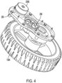
- FIG. 4 illustrates an exemplary motor-driven wheel 130A. In the illustrated embodiment of FIG. 4 , the odometry sensor 255 is positioned adjacent the wheel motor 235A upstream of a gear train 258 which couples the wheel motor 235B to the motor-driven wheel 130A.
- the odometry sensor 255 may also be configured to sense rotation of any component (e.g., a gear) of the gear train 258 and/or the motor-driven wheel 130A itself. Data from the odometry sensor 255 may be scaled according to gear ratios between the wheel motor 235A, the gear train 258, and the motor-driven wheel 130A to properly determine rotation of the motor-driven wheel 130A.
- any component e.g., a gear
- Data from the odometry sensor 255 may be scaled according to gear ratios between the wheel motor 235A, the gear train 258, and the motor-driven wheel 130A to properly determine rotation of the motor-driven wheel 130A.
- the wheel motion sensor(s) 260 may be or include another type (or types) of sensors configured to gather data indicative of motion of the tool 105.
- the wheel motion sensor(s) 260 may be laser or other types of tachometers.
- Such tachometer wheel motion sensor(s) may shine a light source (e.g., a LED light, laser beam or the like) against a tachometer surface of one of the motor-driven wheels 130A and/or the non-motor-driven wheels 130B, or any component of any gear train coupled thereto (e.g., the gear train 258), the light source may be reflected by the tachometer surface, and the tachometer may receive a signal indicating receipt of the light source.
- the tachometer may then determine a time difference in the amount of time for the light to be emitted and received, the time difference being indicative of how fast the motor-driven wheels 130A and/or the non-motor-driven wheels 130B is rotating.
- the wheel motion sensor 260 tracks motion of the robotic tool 105 over time and outputs raw data regarding the detected motion to a processor (e.g., the first electronic processor 205, the second electronic processor 305, and/or the odometry processor 257).
- the processor may then continuously or periodically determine an amount and direction of rotation for any given wheel 130 of the robotic tool 105.
- one wheel motion sensor 260 may monitor the rotation of a left-side motor-driven wheel 130A, and another wheel motion sensor 260 may monitor the rotation of a right-side motor-driven wheel 130A.
- One exemplary wheel motion sensor 260 may detect angular rotation of (e.g., full rotations and/or partial rotations) of at least one of the wheels 130.
- the electronic processor 205 can calculate the arc length of the wheel 130 (e.g., distance traveled over the support surface 50).
- the wheel motion sensors 260 may be configured to intermittently and simultaneously gather data indicative of the position of the corresponding motor-driven wheel 130A. Data may be gathered by the wheel motion sensor 260 at any desired frequency (e.g., 100 Hz, 10 kHz, 1 MHz, etc.) according to the desired accuracy. The data may be collocated along with a timer and/or real-time clock.
- the odometry unit 250 includes an inertial measurement unit (IMU) 275.
- the IMU 275 gathers data indicative of the rotational orientation of the mower body (e.g., roll, pitch, yaw).
- the IMU 275 may include or entirely comprise, for example, an accelerometer, a magnetometer, a gyroscope, and the like.
- the IMU 275 may have a similar data collection frequency (e.g., 100 Hz, 10 kHz, 1 MHz, etc.) when compared to the wheel motion sensor 260 and/or other sensors of the odometry unit 250.
- the IMU 275 is configured to output a signal (or a plurality of signals, e.g., a first signal representing roll, a second signal representing pitch, a third signal representing yaw) representative of the rotational orientation of the robotic tool 105.
- a signal or a plurality of signals, e.g., a first signal representing roll, a second signal representing pitch, a third signal representing yaw
- the odometry unit 250 may include a radar sensor (e.g., a mmWave Radar sensor) 285.
- the radar sensor 285 may be configured to measure relative speed between the robotic tool 105 and an object in the environment of the robotic tool (e.g., the grass, ground, and/or soil of the operating area 605, a tree, a building, etc.).
- the radar sensor 285 is configured to output a signal (or a plurality of signals) representative of the speed of the robotic tool 105 relative to the object in the environment.
- the odometry unit 250 may include a global positioning system (GPS) receiver 270 configured to gather data indicative of the position thereof relative to a remote satellite.
- GPS global positioning system
- the odometry unit 50 may include other types of sensors such as ultrasonic sensors 280, optical sensors 290 (e.g., laser sensors, infrared sensors), and/or the like. Such sensors may gather data indicative of the position of the robotic tool 105, and be configured to export the data for use by the odometry unit 250 to determine the position and orientation of the robotic tool 105 during use.
- the odometry unit 250 may include any combination of the above-described odometry sensors 255 (e.g., the wheel motion sensor 260, the GPS Receiver 270, the IMU 275, the ultrasonic sensor 280, the radar sensor 285, and the optical sensor 290).
- the odometry unit 250 may be configured to receive and combine a plurality of inputs from any combination of the above-described odometry sensors 255.
- the odometry unit 250 may include a wheel motion sensor 260, and an inertial measurement unit (i.e., IMU) 275.
- Data from wheel motion sensor (or sensors) 260 may be combined by the odometry unit 250 or by either the first electronic processor 205 or the second electronic processor 305 with data from the inertial measurement unit to generate a more accurate representation of the position of the robotic tool 105.
- This combination of data may account for, for example, sloped terrain including changes in elevation in an operating area 605 of the robotic tool 105.
- the combination of the data from the wheel motion sensor (or sensors) 260 and data from the inertial measurement unit 275 may otherwise add accuracy to the position of the robotic tool 105.
- the odometry unit 250 may include a wheel motion sensor (or sensors) 260, and a radar (e.g., a mmWave) sensor 285.
- Data from the wheel motion sensor (or sensors) 260 may be combined by the odometry unit 250 or by either the first electronic processor 205 or the second electronic processor 305 with data from the radar sensor 285 to generate a more accurate representation of the position of the robotic tool 105.
- This combination of data may account for, for example, instances in which one or more of the motor-driven wheels 130A are rotated, but the robotic tool 105 does not in fact move in the operating area 605.
- This phenomenon may be described as “wheel slip” or “wheel slippage” of one or more of the motor-driven wheels 130A relative to the environment (e.g., the grass, ground, and/or soil of the operating area 605, a tree, a building, etc.).
- the odometry unit 250 may include a wheel motion sensor (or sensors) 260, an inertial measurement unit 275, and a radar (e.g., a mmWave) sensor 285.
- Data from the wheel effect sensor (or sensors) 260 may be combined by the odometry unit 250, the first electronic processor 205, or the second electronic processor 305 with both data from the inertial measurement unit 275 and data from the radar sensor 285 to generate a more accurate representation of the position of the robotic tool 105.
- This combination of data may account for, for example, both sloped terrain including changes in elevation in the operating area 605 as well as any slipping motor-driven wheels 130A.
- the robotic tool 105 also includes a timer and/or a real-time clock that may be implemented by the first electronic processor 205.
- the timer and/or real-time clock may be used in conjunction with the odometry unit 250 to collocate data gathered by at least one odometry sensor 255 and ultimately to determine a distance that the robotic tool 105 has traveled from any given start point 615 and/or the docking station 110.
- the robotic tool 105 further comprises an uninterruptible power source, such as a button cell battery or battery pack, which may be charged by either the docking station 110 and/or the battery 245.
- the uninterruptible power source may provide power to the timer and/or the real-time clock to ensure accuracy of the timer and/or real-time clock in the event that the battery 245 is depleted.
- the first electronic processor 205 may use stored scheduling information and/or retrieved scheduling information to control times at which the robotic tool 105 is configured to operate, dock, etc. Such scheduling information may be stored in the first memory 210, the second memory 310, and/or the memory of the server 152.
- the corresponding data can be saved in any memory (e.g., by a memory of the odometry unit 250 (not shown), the first memory 210, the second memory 310, and/or a memory of the docking station 110 or the server 152) for future use.
- the second set of data points are compared (e.g., by the odometry processor 257 or the first electronic processor 205) to the second set of data points.
- the odometry unit 250 may determine whether the left side motor-driven wheel 130A was rotated forwards an amount greater than the right side motor-driven wheel 130A. This is indicative of a right-hand turn of the robotic tool 105 as the robotic tool 105 is driven forwards. Other corresponding comparisons may be made for left-hand turns, straight travel, reverse travel, as well as left-handed and right-handed turning reverse travel. Further sets of data points are gathered at the desired data collection frequency (e.g., 100 Hz, 10 kHz, 1MHz, etc.) to continuously monitor the position of the robotic tool 105. Data generated by the odometry unit 250 need not continuously be saved to memory. In some embodiments, only portions of data may be saved, and/or data may be saved and then subsequently erased (e.g., in a first in-first out basis, when it is no longer needed, or the like) to avoid requiring large amounts of memory.
- desired data collection frequency e.g. 100 Hz, 10 kHz, 1MHz, etc.
- FIG. 3 is a block diagram of the external device 115 according to some example embodiments.
- the external device 115 includes a second electronic processor 305 electrically connected to a second memory 310, a second network interface 315 (i.e., device network interface 315), a second user input device 320, and a second display 325.
- a second network interface 315 i.e., device network interface 315
- a second user input device 320 i.e., device network interface 315
- the second display 325 may also function as an input device (e.g., when the second display 325 is a touchscreen).
- the second network interface 315 includes one or more transceivers for wirelessly communicating with the robotic tool 105 (e.g., a second RF transceiver configured to communicate via Bluetooth TM , WiFi TM , or the like).
- the second network interface 315 may include an additional transceiver for wirelessly communicating with the server 152 via, for example, cellular communication.
- the second network interface 315 may also include a second GPS receiver configured to receive a location signal from one or more satellites.
- at least some of the transceivers and/or receivers of the external device 115 may be combined or share some elements (e.g., an antenna and/or other hardware).
- the second electronic processor 305 sends data to and receives data from the robotic tool 105 and/or other devices of the communication system 100 via the second network interface 315.
- the external device 115 may be, for example, a smart phone (as illustrated), a laptop computer, a tablet computer, a personal digital assistant (PDA), a wireless communication router that allows another external device 115 that is located remotely from the robotic tool 105 to communicate with the robotic tool 105, or another electronic device capable of communicating with the robotic tool 105.
- the external device 115 may generate a user interface on a display (described below) and allows a user to access and interact with robotic mower information in real time.
- the external device 115 may receive user inputs to determine operational parameters/instructions for the robotic tool 105, enable or disable features of the robotic tool 105, and the like.
- the communication between the external device 115 and the robotic tool 105 may be wired (e.g., via a Universal Serial Bus (USB) cord configured to connect to respective USB ports of the external device 115 and the robotic tool 105).
- USB Universal Serial Bus
- the user can interact with the external device 115 to control operation and/or future operation of the robotic tool 105.
- the external device 115 includes fewer or additional components in configurations different from that illustrated in FIG. 3 .
- the external device 115 may include a battery, a GPS receiver, or the like.
- the external device 115 performs functionality other than the functionality described below.
- the server 152 includes similar elements as at least some of the elements described above with respect to the devices 105, 115 that function in a similar manner.
- the server 152 may include an electronic processor, a memory, and a network interface, among other elements.
- FIG. 8 illustrates one exemplary embodiment of a boundary screen 805 to be displayed on the second display 325 of the external device 115.
- the boundary screen 805 includes a map portion 810 and an interaction-display portion 815.
- the map portion 810 of the boundary screen 805 may be configured to overlay a series of indicia and/or other indicators onto a map of the operation area 605 to provide the user a visual representation of the current operational status of the system 100.
- the boundary screen 805 may illustrate a generic map portion 810 which does not exactly replicate the operation area 605.
- the boundary screen 805 may not replicate the landscape of the operation area 605 as calculated by the odometry unit 250 but rather may include some pre-determined boundary outline (e.g., a generic house with driveway surrounded by a polygonal boundary).
- a two-dimensional map of the operation area 605 may be provided, such as the map portion 810 illustrated in FIG. 8 .
- This map portion 810 may or may not be representative of the actual dimensions of the operation area 605 and/or the boundary 610.
- a one-dimensional line segment (e.g., the line segments 940, 960, described below with regard to FIG. 9A ) may represent the perimeter 610.
- the underlying map may include, but is not limited to, a user generated image of the desired region, a satellite image of the desired region, a computer-generated image of the desired area, and the like.
- the illustrated map portion 810 includes a dock indicator 110A configured to represent the relative location of the docking station 110 within the operation area 605, a mower indicator 105A configured to represent the relative location of the robotic tool 105 within the operation area 605, an operating area map 605A configured to depict the general layout and shape of the operating area 605, and a perimeter indicator 610A configured to display the location of the perimeter 620 (e.g., the boundary wire 608) with respect to the operating area 605.
- obstacle indicators 610B may be provided on the map portion 810. As shown in FIG. 8 , the obstacle indicators 610B may be, for example, sized to approximate the corresponding size of the obstacle it is configured to represent (e.g., the outer size and shape thereof) within the operating area 605. The obstacle indicators 610B may be positioned and/or sized to represent, for example, a building, tree, driveway, planter, garden, and other non-operating areas of the robotic tool 105 (e.g., non-mowable obstacles). As illustrated in FIG. 8 , the perimeter indicator 610A may envelope but not pass through the obstacle indicators 610B.
- the obstacle indicators 610B may be adjustable in color and/or shape to correspond to the type of obstacle that they represent (e.g., a driveway may be colored grey, a tree may be colored a shade of green different than another shade of green of the operating area map 605A which represents the operating area 605, etc.).
- the boundary screen 805 may update (e.g., automatically, contiguously, intermittently, etc.) the position of the mower indicator 105A with the sensed position (via the odometry unit 250) of the robotic tool 105 in the operating area 605. In other embodiments, the boundary screen 805 may not update the position of the mower indicator 105A with the sensed position of the robotic tool 105.
- the boundary screen 805 may be an accurate scaled representation of the size and shape of the operating area 605 and perimeter 610 with each indicator located in its real-time position. However, in other embodiments the boundary screen 805 may simply be display a generic representation of an operating area 605 and perimeter 610 with the indicators positioned in general positions. In some embodiments, the user may be able to zoom in, zoom out, and/or select the various indicia being displayed.
- the interaction-display portion 815 of the boundary screen 805 may include a series of buttons and/or indicators through which the user may interact with the system 100 during use.
- the interaction-display portion 815 includes a boundary length indicator 820, an "initiate setup” button 830, an "add start point” button 835, a "complete” button 840, and a "quit boundary” button 845.
- more or fewer buttons and/or indicators may be present.
- the text on the buttons 830-845 may differ from the illustrated text.
- the "add start point” button 835 may be a "modify start point” button 835.
- the "initiate setup” button 830 is configured to instruct the system 100 (e.g., the external device 115 and tool 105) to initiate a setup sequence (described below).
- the "add start point” button 835 (and/or “modify start point” button) is configured to command the system 100 to add (and/or modify) a start point 615 to the existing list of start points.
- selecting the "add start point” button 835 may cause the system 100 to communicate (e.g., retrieve), via the odometry unit 250, data relating to the position of the robotic tool 105, and to add a start point 615 at the current location of the tool 105 relative to the perimeter 620.
- selecting the "add start point” button 835 may cause a start point 615 to be added to a pre-determined position along the perimeter 810 whereby the user can later adjust the location of the start point 615 to the desired position.
- the button 835 may transition to the "modify start point button” while the robotic tool 105 is adjacent the corresponding start point 615.
- the "modify start point” button 835 When the "modify start point” button 835 is depressed, the user may be prompted to input a desired adjustment (e.g., +/- 0.1 meter along the perimeter 610) and/or revised position (e.g., as a percentage of overall length and/or a desired position (e.g., 10 meters] relative to the docking station 110) for the start point 615.
- a desired adjustment e.g., +/- 0.1 meter along the perimeter 610
- revised position e.g., as a percentage of overall length and/or a desired position (e.g., 10 meters] relative to the docking station 110
- the button 835 may transition back to the "add start point button” automatically. Additionally or alternatively, the "modify start point” button 835 may permit the user to delete any given start point.
- the "complete” button 840 may be configured to save the positions of any start points 615 present at that time.
- the “complete” button 840 may also be configured to end or conclude the initialization process (described below).
- the "quit boundary” button 845 is configured to exit or otherwise close the program.
- the interaction-display portion 815 is positioned below the map portion 810. This may be reversed. Additionally, the various indicators and buttons 820-845 within the interaction-display portion 815 may be rearranged to any desired configuration relative to one another.
- FIGS. 9A-9D illustrate screenshots of example screens/graphical user interfaces that may be displayed on the second display 325 of the external device 115.
- FIGS. 9A-9D illustrate the start point screen 905 in different situations that are explained below.
- the start point screen 905 includes information related to the overall length of the perimeter 610, and the position of the start points 615A-615C with respect to the perimeter 610.
- at least some of the information related to the robotic tool 105 that is displayed on the start point screen 905 may be wirelessly received by the external device 115 from the robotic tool 105.
- the start point screen 905 includes a plurality of display areas 910A-910D.
- a first display area 910A thereof includes a slider or toggle 915 configured to enable and/or disable the variable start point feature of the robotic tool 105.
- the slider 915 When the slider 915 is in the enabled position (see FIG. 9A ) the display areas 910A-910D are enabled and free to be manipulated by the user (e.g., via the touch screen of the external device 115).
- the system is also configured such that the tool 105 will operate using the variable start point capability as prescribed by the display areas 910A-910D (described below).
- the interaction portions 910A-910D may be disabled and no longer accessible by the user.
- the start point screen 905 visually represents a disabled slider 915 by displaying the interaction portions 910A-910D in light grey tones. In other embodiments, the start point screen 905 may go blank or remove the relevant information when the slider 915 is disabled. Accordingly, the system 100 is configured such that the robotic tool 105 will not start from any set points saved on the first memory 210, the second memory 310, the memory of the server 152, or the memory of the docking station 110 when the variable start point slide 915 is in the disabled position.
- the robotic tool 105 may simply begin operation from the docking station 110. Similarly, when no start points 615A-615C have been generated (e.g., saved), the robotic tool 105 may simply begin operation from the docking station 110.
- the first display area 910A of the start point screen 905 further includes an indicator 920 which displays the overall linear length of the perimeter 610. More specifically, the indicator 920 includes text indicative of the length of the perimeter 610 (e.g., "100 m", "100 meters”, or the like). In the illustrated embodiment, an arrow or other indicia positioned adjacent to the indicator 920 signals to the user that the length of the perimeter 610 may be adjusted by interacting (e.g., tapping, clicking) with the indicator 920 via the second input device 320 (e.g., a touch screen, mouse, etc.). Upon interacting with the indicator 920, a keypad 925 ( FIG. 9B ) and/or a rotary selector 930 ( FIG.
- the keypad 925 and the rotary selector 930 may each present a plurality of options for the user to adjust characteristics of the system 100.
- Other types of graphical user interfaces for gathering user input(s) may be displayed on the start point screen 905, such as but not limited to drop down menus, a plurality of checkboxes, radio buttons, toggle switches, and the like.
- the user may interact with the second input device 320 (e.g., the touch screen, mouse) to input a known length of the perimeter 610 via the keypad 925 or the rotary selector 930.
- a boundary length may be calculated automatically as part of the initial setup state (described below).
- the second input device 320 may be used in conjunction with the indicator 920 to adjust the length of the perimeter 610 after having been calculated by the odometry unit 250.
- the user may be prompted by the device to confirm that the perimeter length should be adjusted and/or be prompted to return the robotic tool 105 to the docking station 110 to run the initial setup state again (described above). More specifically, if the perimeter length input by the user via the second input device 320 is less than the calculated boundary length of the odometry unit 250, the boundary length may be updated to the boundary length input by the user via the second input device 320.
- start points 615 must be removed to accommodate the newly entered boundary length (e.g., are positioned outside the newly established range)
- the user may be informed of which start point 615 may be deleted by the shortening of the boundary length.
- the user may then either select that the effected start point 615 can be deleted and/or to locate the start point 615 at the extreme end of the perimeter 610 (e.g., at the docking station 110).
- the user can then adjust the position of the effected start point 615 by moving the start point indicator 950 towards the first end 940A a desired amount such that the start point 615C is positioned on the perimeter 610 and not coincident with the docking station 110.
- the perimeter length may be saved in the first memory 210, the second memory 310, the server 152, and/or the docking station 110. Any existing perimeter length data may be overwritten as needed.
- the updated perimeter length may then be displayed on the start point screen 905 via the indicator 920.
- the first display area 910A further includes a start point number indicator 935 indicative of a total number of start points 615 on the perimeter 610.
- the start point number indicator 935 may include text indicative of the number of start points 615 currently saved in memory (e.g., "3", or the like).
- An arrow or other indicia may be positioned adjacent to the start point number indicator 935 to indicate to the user that the total number of start points 615 may be adjusted by interacting (e.g., tapping, clicking) with the start point number indicator 935 via the second input device 320 (e.g., a touch screen, mouse).
- the user may interact with the second input device 320 (e.g., the touch screen, mouse) to input a desired number of start points 615 via the keypad 925 or the rotary selector 930.
- the second input device 320 e.g., the touch screen, mouse
- any configuration of start points 615 may be suitable.
- the default setting may be to space each start point 615A-C evenly over the entire length of the perimeter docking station 110 (e.g., at 25m, 50m, and 75m from the docking station 110).
- the start points may be spaced randomly over the perimeter length.
- the start point number indicator 935 may be automatically populated during the setup and initialization processes (described below).
- the total number of start points 615 may be increased or decreased according to a user's desired number of start points 615A-615C.
- the user may be prompted to add the additional start points 615 to a desired position along the perimeter 610.
- the additional start point 615 may be added to a pre-determined default location along the perimeter 610 (e.g., at the docking station 110, halfway along the perimeter 610, at another position along the boundary, and the like).
- the additional start point may be positioned at a preset position relative to other existing start points (e.g., halfway between a start point and either another start point and the dock).
- the user may be prompted to select one or more start points 615 to be removed/deleted.
- the remaining start points can be validated and/or adjusted as the user sees fit.
- the second display area 910B relates to the position of the start points 625A-C of the robotic tool 105 with respect to their position along the length of the perimeter 610. More specifically, the second display area 910B provides a more visual representation of the location of the start points 615A-C along the length of the perimeter 610.
- the second display area 910B includes a line segment 940 having a first end 940A, an opposite second end 940B, a first end indicia 945A positioned adjacent the first end 940A, and a second indica 945B positioned adjacent the second end 940B.
- the line segment 940 may otherwise represent the perimeter 610 in another form.
- the line segment 940 may be replaced by an enclosed box (e.g., rectangle), an open box (e.g., an open line segment), an actual map (e.g., the map portion 810), or the like.
- the first end indicia 945A may indicate a relative position of the first end 945A of the line segment 940 relative to the docking station 110.
- the first end indicia 945A will display "0", “0 m”, “0 meters”, or the like, as the docking station 110 may function as a home position of the tool 105.
- the second end indicator 945B may indicate a current and/or full length of the perimeter 610. The second end indicator 945B typically will match the text of the indicator 920.
- each start point indicator 950 includes a symbol or indicia (e.g., a circle) positioned on the line segment 940 in a position generally corresponding to the position of the represented start point 615A-C. While the illustrated indicators are circular, other types of start point indicators 950 may also be used (e.g., arrow, star, polygonal, or otherwise shaped). In some embodiments, each indicator 950 may include a label or have a unique shape to allow the user to more easily identify what start point 615A-C each indicator 950 represents (see label 984 of FIG. 9E ).
- the line segment 940 and the start point indicators 950 are differently colored to improve contrast. In other embodiments, the line segment 940 and the start point indicators 950 may be the same color. Furthermore, each start point indicator 950 is proportionally placed between the first end 940A and the second end 940B of the line segment 940 an amount corresponding to a length along the perimeter 610 between the docking station 110 and the corresponding start point 615A-C.
- the length of the gap between the left-most start point indicator 950 and the first end 950A of the line segment 940 is 20% of the overall length of the line segment 940 (e.g., the distance between the first end 950A and the second end 950B) because the left-most start point indicator 950 is representative of the first start point 615A which, in turn, is positioned 20 meters from the docking station 110 where the overall length of the perimeter 610 is 100 meters.
- the start point indicator 950 provides accurate, to-scale visual representation of the position of each start point 615A-615C with respect to the overall length of the perimeter 610.
- the start point 615 may be represented by positioning the corresponding start point indicator 950 at one of the first end 940A and/or the second end 940B of the line segment 940.
- the start point indicators 950 may be positioned adjacent to or along the other form in correspondence to the proportionality of the start points 615A-615C relative to the docking station 110.
- start point indicia or labels 955 are positioned below the line segment 940 and adjacent to a corresponding start point indicator 950.
- the illustrated start point indicia 955 include text (e.g., "20m”, “50m”, “90m") indicative of a length between the docking station 110 and the start point 615A-C being represented by that particular indicia 950.
- the second display area 910B is also configured to allow the user to independently adjust (i.e., edit) and/or modify the relative locations of each of the start point indicators 950, and as a result, the physical location of the start points 615A-615C along the length of the perimeter 610. More specifically, the user is able to independently adjust the relative location of any one of the start points 615A-615C by selecting and dragging the relevant indicator 950 to the desired location.
- the user can select and drag the left-most indicator 950 toward the first end 940A until it is positioned at 10% of the overall length of the line segment 940 (e.g., at the 10m position).
- the user may independently modify the relative locations of each start point 615A-C by selecting the indicator 650 corresponding to the start point 615A-C the user wishes to move. Once selected, the display may provide a prompt to allow the user to enter the exact location (in meters, percentage, and the like) where the start point 615 should be located. The display will then automatically move the indicator 650 to represent the new location.
- both the "drag and drop" and "prompt" concepts may be used.
- the start point indicators 950 may be adjusted in a similar manner (e.g., by dragging the start point indicator 950 along the actual map, etc., or by entering an exact location where the start point 615 should be located) to the start point indicators 950 positioned along the line segment 940.
- the third display area 910C relates to the relative frequency at which each of the start points 615A-615C of the robotic tool 105 are utilized during operation. More specifically, the third display area 910C provides a graphical representation of the relative frequency at which the robotic tool 105 begins a session from each start point (discussed below).
- the third display area 910C includes a line segment 960 having a first end 960A, and a second end 960B opposite the first end 960A.
- the first end indicia 965A is positioned adjacent the first end 960A and labels the beginning of the line segment 960.
- the first end indicia 945A displays "0".
- the first end indicia 945A may display "0%” or the like.
- the second end indicator 945B is positioned adjacent the second end 960B and labels the end of the line segment 960.
- the second end indicia 965B displays "100%”.
- the second end indicia 965B may display "100" or the like.
- the third display area 910C also includes a plurality of frequency adjustment indicators 970 positioned along the line segment 960 that, together, are configured to generally represent the frequency at which the tool 105 will begin a session from a particular start point 615A-615C.
- the line segment 960 may otherwise represent an operating frequency of the robotic tool 105 at a desired start point 615A-615B.
- the line segment 960 may be replaced by a pie chart, a doughnut chart, a tree map, a two-dimensional segmented column chart, and the like.
- the third display area 910C is configured so that the size of the gap between the end indicia 960A, B and/or the indicators 970 themselves are scaled to represent the frequency each start point 615A-C is utilized.
- the size of the left-most gap e.g., between the first end indicia 960A the left-most indicator 970
- the size of the left-center gap e.g., between the left-most indicator 970 and the central indicator 970
- the size of the right-center gap e.g., between the central indicator 970 and the right-most indicator 970
- the right-most gap generally corresponds to the frequency at which the tool 105 will depart from the final start point 615C positioned furthest from the home position
- the right-most gap e.g., between the left-most gap between the first end indicia 960A the left-most indicator 970
- the third display area 910C may include one less indicator 970 than the number of start points 615A-C so the number of gaps present matches the number of start points 615A-C (see FIG. 9E ).
- the frequency indicators 970 may be represented as lines between adjacent pie segments. Other similar frequency indicators 970 are possible.
- the frequency adjustment indicators 970 are circularly shaped, and are positioned on the line segment 940.
- other types of frequency adjustment indicators 970 e.g., arrow, star, polygonal, or otherwise shaped
- each indicator may include a label or have a unique shape to allow the user to more easily identify what start point 615A-C corresponds with each gap (see labels 985 of FIG. 9E ).
- the line segment 960 and the frequency adjustment indicators 970 are differently colored. In other embodiments, the line segment 960 and the frequency adjustment indicators 970 may be the same color.
- a plurality of frequency indicia 975 are positioned below the line segment 940 and between two corresponding frequency adjustment indicators 970 and/or end indica 960A, 960B.
- each of the plurality of frequency indicia 975 are centered between two adjacent corresponding frequency adjustment indicators 970.
- the frequency indicia 975 include text (e.g., "40%", “20%”, “30%", 10%) indicative of a frequency with which the robotic tool 105 may begin mowing (e.g., begin a session) from a corresponding start point.
- the third display area 910C is also configured to allow the user to independently adjust and/or modify the frequency at which the tool 105 will depart any given start point 615A-C and/or the docking station 110. More specifically, the user is able to independently adjust the relative frequency for any one of the start points 615A-615C by selecting and dragging the relevant indicator 970 to the desired location. For example, if the user wishes to decrease the frequency of the first start point 615A, the user can select and drag the left-most indicator 970 toward the first end 960A until it is positioned closer thereto. By doing so, the user is decreasing the size of the left-most gap while also simultaneously increasing the size of the left-center gap.
- each percentage point reduced from the first start point 615A will be added to the second start point 615B.
- the third display area 910C automatically maintains the requisite 100% total frequency for all of the start points 615A-C and the docking station 110.
- the frequency indicators 970 adjusted between adjacent pie segments in manners similar to the above-described adjustment of the frequency indicators 970 (e.g., by dragging a line between adjacent pie segments, entering a desired start point frequency percentage). Other similar means to adjust the frequency indicators 970 are possible.
- the user can select and drag the right-most indicator 970 to the right until it is coincident with the second end 960B.
- the right-most gap is eliminated setting the frequency value for the docking station 110 to 0%, at the same time, the user also increases the size of the right-center gap such that the third start point 615C will now have a frequency of 40% (see FIG. 9E ).
- the start point screen 905 further includes a fourth display area 910D.
- the fourth display area 910D includes a plurality of buttons and/or indicators for the user to interact with. More specifically, the fourth display area 910D includes an "initiate setup" button 1030, an "add start point” button 1035, a “complete” button 1040, and a "quit boundary” button 1045. These buttons are similar to the above-described buttons of the boundary screen 805 and therefore will not be described in detail herein. Additional or fewer user actuatable buttons may be provided on the start point screen 905.
- the first display area 910A, second display area 910B, the third display area 910C, and the fourth display area 910D are aligned with one another in a vertical direction (as viewed in FIG. 9A ) on the second display 325.
- only some of the display areas 910A-910D may be aligned with one another in the vertical direction of the second display 325.
- the second display area 910B and the fourth display area 910D may be aligned in the vertical direction, while the third and fourth display areas 910A, 910D are otherwise positioned on the second display 325 or missing from the display 325.
- the first display area 910A is at a top of the second display 325 as viewed in FIG.
- the remaining display areas 910B-910D are provided below the first display area 910A in a sequential manner.
- the order of the display areas 910A-910D in the height direction may differ.
- the orientation and visual appearance of the individual line segments 940, 960 may also differ in other embodiments.
- the illustrated line segments 940, 960 are oriented horizontally, it is understood that in other embodiments different forms of visual user interface may be used such as, but not limited to, vertical line segments, vertical and/or horizontal bars, a number of user-manipulatable dials, text fields, and the like.
- the robotic tool 105 may be in any one of a plurality of states at any given time.
- the plurality of states include, but are not limited to an initial setup state, a modification state (i.e. to add, delete, or modify start point), a validation state, a combined initial setup and validation state (e.g., a combined state), a general operational state, a paused state, a perimeter cutting state, a perimeter walking state, a docking state, a charging state, a standby state, and an error state.
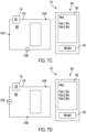
- the robotic mower 105 When operating in the initial setup state, the robotic mower 105 is configured to establish one or more start points 615 along the perimeter 610 of the operating area 605. To place the system 100 in the initial setup state, the user first actuates a button (e.g., the initiate setup button 830 on the boundary screen 805 or the initiate setup button 1030 on the start point screen 905) on the second input device 320 (e.g., the touch screen) of the external device 115.
- a button e.g., the initiate setup button 830 on the boundary screen 805 or the initiate setup button 1030 on the start point screen 905
- the second input device 320 e.g., the touch screen
- the external device 115 begins to display the initialization startup screen 705 on the second display 325 (see FIG. 7A ), and 2 ) the external device 115 transmits, via the second network interface 315 of the external device 115, a command to the tool 105 to return to the docking station 110.
- the tool 105 will begin to travel back toward the docking station 110 either directly and/or by traveling along the perimeter 610 (e.g., via the boundary wire 608).
- the tool 105 may also output an audio and/or visual signal to indicate that it has entered the initial setup state.
- the "start" button on the initialization startup screen 705 will become active on the external device 115 (see FIG. 7A ).
- the user may then select the start button 710 whereby the external device 115 will transmit a command to the tool 105, via the second network interface 315, to begin advancing along the perimeter 610 in a first direction (e.g., in a clockwise direction).
- the robotic tool 105 Upon receiving the command from the external device 115, the robotic tool 105 travels along the perimeter 610 in the first direction under its own control, relying on any one of the electromagnetic signals output by the boundary wire 608 and/or the odometry unit 250 for guidance and telemetry.
- the robotic tool 105 could be moved along the perimeter 610 under manual control by the user (e.g., via remote control, and/or physical movement of the robotic tool 105 by the user). This would allow the user to define not only establish the perimeter 610 of the operating area 605, but further internal boundaries within the perimeter 610 for representing non-operating areas (e.g., buildings, trees, driveways, etc.).
- the odometry unit 250 of the robotic tool 105 is simultaneously measuring the current distance and/or trajectory of the robotic tool 105 has traveled along the perimeter 610 with respect to the home position (e.g., the docking station 110).
- the current linear distance between the tool 105 and the home position, as measured along the perimeter 610 is referred to as the "current travel distance.”
- the user selects the "add point" button 735 of the initialization startup screen 705 on the external device 115 (see Fig. 7B ). By doing so, the external device 115 outputs a command to the tool 105 to record and output the current travel distance. Once the current travel distance is received by the external device 115, the device 115 displays an entry 740 on the second display 325 both confirming the start point 615A has been recorded and providing the details of the newly established start point 615A.
- such details include listing the start point name or identification number (e.g., start point 615A is assigned the name "Point 1"), and displaying the linear distance between the start point 615A and the home position measured along the perimeter 610 (e.g., 20 m, see FIG. 7B ).
- the odometry data indicative of the first start point 615A may then be stored by any of the first memory 210, the second memory 310, and/or the memory of the server 152.
- the tool 105 may pause momentarily and/or output some form of audio and/or visual signal to confirm that the start point 615A has been created.
- the tool 105 will resume traveling along the perimeter 610 in the first direction (e.g., in a clockwise direction) continuing to monitor and record the current travel distance and/or trajectory via the odometry unit 250.
- the tool 105 reaches the desired location for the second start point 615B, the user again selects the "add point" button 735 of the display 795 on the external device 115.
- the external device 115 causes the external device 115 to output a command to the tool 105 to record and output the current travel distance whereby the external device 115 will assign the point a name or identification number (e.g., start point 615B is assigned the name "Point 2"), and display the linear distance between the start point 615B and the home position (e.g., 50m; see FIG. 7C ). The user is then able to repeat this process until all of the desired start points 615A-C have been recorded and displayed in the manner discussed above (see FIG. 7D ).
- start point 615B is assigned the name "Point 2”
- the tool 105 is configured to dock with the docking station 110 (when present) and record the overall perimeter distance and/or trajectory traveled via the odometry unit 250.
- the overall perimeter distance is then transmitted to the external device 115, via the first network interface 215.
- the external device 115 is configured to display the overall perimeter length 745 on the second display 325 and enable the "finish" button 747 (see FIG. 7E ).
- the external device 115 is configured to display the map portion 810 representative of calculated dimensions of the perimeter 610.
- the user can then select the finish button 747 to exit the initial setup state and save all of the newly formed start points 615A-C and perimeter data in any one of the first memory 210, the second memory 310, and/or the memory of the server 152.
- the tool 105 may continue to loop the perimeter 610 (e.g., multiple times) until the user has created all of the desired start points 615A-C and selected the "finish" button 747. More specifically, the robotic tool 105 may take one or more laps around the perimeter 610 and relative to the docking station 110 in the initial setup state. None, one, or more than one start points 615A-615C may be saved during each lap around the perimeter 610 in the initial setup state. When calculating the boundary length, the robotic tool 105 may account for the number of laps around the perimeter 610 taken relative to the docking station 110.
- the robotic tool 105 may take a first lap around the perimeter 610 and relative to the docking station 110.
- the odometry unit 250 may gather odometry data and calculate the boundary length.
- a subsequent lap i.e., a start point setting lap
- the user may actuate the add start point button 1035 via the second input device 320 to set a start point (e.g., the start point 615A) along the perimeter 610. Any number of laps may be taken.
- the screen 705 may include a button or feature allowing the user to individually select and delete specific start points 615 while remaining in the initial setup state. For example, if the user presses the "add point" button 735 at the wrong time (e.g., establishing a start point 615 in an undesired location) the screen 705 may have a button or feature whereby the offending start point 615 can be selected and deleted.
- the system 100 may include an alternative initial setup state whereby the user may use the external device 115 in place of the tool 105 to establish the start points 615A-C.
- the user Before the alternative initial setup state can be executed, the user may undergo some form of perimeter initialization.
- a perimeter initialization may include having the tool 105 with an odometry unit 250 travel along and record the telemetry of the entire perimeter 610 of the operating area 605.
- a perimeter initialization may occur when the user manually enters the layout and shape of the perimeter 610 into the device 115 (e.g., by entering the coordinates of waypoints and the like).
- the perimeter initialization may occur by having a computer-generated layout created based on one of a satellite image or other map of the operating area 605.
- a perimeter initialization may include the user having gone through the primary initial setup state discussed above.
- the user may then enter the "alternative initial setup state" by selecting the necessary buttons on the second display 325 of the external device 115 (not shown). Once selected, the external device displays the initialization startup screen 705 or some variant thereof. The device 115 also activates and aligns the GPS or other location capabilities included thereon.
- the user can then walk directly to the location where he or she wishes the first start point 615A to be located. Once there, the user can select the "add point" button 735 whereby the GPS system of the device 115 records the present location of the device 115.
- the second electronic processor 305 is configured to compare and contrast the GPS data recorded by the device 115 with the initialized perimeter data discussed above.
- the second electronic processor 205 then enters the comparative data into one or more algorithms saved in the second memory 310 whereby the second electronic processor 305 establishes the first start point 615 at the point of the perimeter 610 located closest to the recorded GPS location.
- the algorithm then also calculates the current travel distance based on the initialized perimeter data. With the location and current travel distance established, the device 115 may then display the start point name and current travel distance on the second display 325 as discussed above. The user can then repeat this process until all of the desired start points 615A-C are created.
- the user may walk along the perimeter 610 of the operating area 306 whereby the second electronic processor 305 will operate in a similar manner to that described with respect to the tool 105 above - only substituting the compiled GPS data from the device 115 for the odometry unit 250 data.
- the system 100 may be placed in a "validation state" whereby the user is able to individually confirm that the start points 615A-C are each in a desired position and, if one or more of the start points 615 are misplaced, adjust the position of the start point 615 along the length of the perimeter 610.
- the user may interact with the second input device 320 (e.g., the touch screen) of the external device 115. More specifically, when the user is viewing the start point screen 905, the user may actuate the "validate mode" icon 750 - changing the icon 750 to the enabled condition and placing the system 100 in the validation state.
- the second input device 320 e.g., the touch screen
- the user is then generally able to select any one of the start point indicators 950 whereby the system 100 will "validate" the start point position already stored in memory by instructing the tool 105 to physically travel to and stop at the saved position along the perimeter 610 of the operating area 605. If the indicated position is undesirable, the user may then manipulate the selected start point position (e.g., by sliding the corresponding start point indicator 950 along the line segment 940, described above), whereby the system 1000 will output instructions to the tool 105 so that any changes instituted by the user on the second display 325 of the external device 115 via the second input device 320 are physically carried out and reproduced in real-time along the perimeter 610 of the operating area 605 by the tool 105 itself.
- the system 1000 may then manipulate the selected start point position (e.g., by sliding the corresponding start point indicator 950 along the line segment 940, described above), whereby the system 1000 will output instructions to the tool 105 so that any changes instituted by the user on the second display 325 of the external device 115 via the second input
- the external device 115 begins by displaying start point screen 905 whereby each of the entries shown represents the current operating conditions of the system 100.
- the second display area 910B includes a line segment 940 with a plurality of start point indicators 950 positioned thereon.
- the indicators 950 are positioned to represent the current saved start point 615 locations.
- the left-most start point indicator 950 represents the saved location of the first start point 615A which is 20 meters from the home position
- the middle start point indicator 950 represents the saved location of the second start point 615B which is 50m from the home position
- the right-most indicator 950 represents the saved location of the third start point 615C which is 90 meters from the home position.
- the second display area 910B also includes a second end indicator 945B which displays the current saved overall perimeter length of the perimeter 610, which in the illustrated embodiment is 100 meters.
- the system 100 may also output instructions to the tool 105 instructing it to return to the home position (e.g., return to and dock with the docking station 110).
- the tool 105 may output audio and/or visual signals indicating that it has entered into the validation state.
- the user To validate one of the start point positions, the user must first select the indicator 950 corresponding to the desired start point 615A-C. For example, if the user wants to validate the first start point 615A, he or she may do so by selecting (e.g., taping on) the left-most start point indicator 950. Upon selecting the left-most start point indicator 950, the external device 115 is configured to output commands, via the second electronic processor 305, to the tool 105 instructing the tool 105 to travel along the perimeter 610 in the first direction (e.g., clockwise) for 20 meters.
- the first direction e.g., clockwise
- the external device 115 may also display some form of acknowledgement (e.g., having the point indicator 950 change colors, begin blinking, change shape, and the like) to signal to the user that the command was received and in the process of being executed.
- some form of acknowledgement e.g., having the point indicator 950 change colors, begin blinking, change shape, and the like
- the external device 115 may switch to an alternative screen layout emphasizing the current position of the first start point 615A and the options available to the user.
- the robotic tool 105 Upon receiving the command from the external device 115, the robotic tool 105 travels along the perimeter 610 in the first direction (e.g., clockwise) under its own control, relying on any one of the electromagnetic signals output by the boundary wire 608 and/or the odometry unit 250 for guidance and telemetry. Furthermore, the odometry unit 250 of the robotic tool 105 simultaneously measures the current distance the robotic tool 105 has traveled away from home position. Once the odometry unit 250 signals that 20 meters has been traversed, the robotic tool 105 comes to a stop. In some embodiments, the robotic tool 105 may also be configured to output a visual and/or audible signal to signify that the instructed location has been successfully reached.
- the robotic tool 105 may also be configured to output a visual and/or audible signal to signify that the instructed location has been successfully reached.
- the user may then adjust the position via the external device 115. More specifically, the user may select and drag the left-most point indicator 950 along the line segment 940 until the indicator 950 is in the desired location. For example, if the user believes the first start point 615A is too far from the docking station 110, the user may select and drag the left-most point indicator 950 to the left (e.g., toward the first end 940A) to the desired location (e.g., to a 10m position).
- the updated location is saved in memory and the difference in position calculated by the second electronic processor 305.
- the external device 115 outputs a command to the tool 105 instructing it to travel 10m closer to the home position (e.g., toward the docking station 110).
- the robotic tool 105 travels along the perimeter 610 in a second direction (opposite the first direction) under its own control until the odometry unit 250 signals that 10 meters has been traversed.
- the tool 105 then comes to a stop at the updated location. The user is able to repeat the above described process until the first start point 615A is in the desired location.
- the first start point 615A may be repositioned to an adjusted (i.e., edited) first start point 615D.
- This adjusted first start point 615D may be saved to any viable memory (e.g., the first memory 210, the second memory 310, memory of the docking station 110, and/or memory of the server 152) for future recall.
- the user may then validate another start point 615B, 615C by selecting another point indicator 950 as described above.
- the external device 115 outputs commands to the tool 105 causing it to travel along the perimeter 610 until it is in a position corresponding to the saved position for the newly selected start point 615B, 615C.
- the user is then free to independently change the location of the selected start point 615B, 615C as described above.
- the user may then re-select the validation mode icon 750 - changing the status to "disabled.” By doing so, the system 100 exits the validation state and any additional changes to the locations of the start points 615A-C will not be carried out by the tool 105.
- the system 100 may include a combined initial setup state and validation state (e.g., a combined state).
- a combined state the robotic tool 105 is configured to travel along the perimeter 610, receiving instructions from the external device 115 to add a start point 615A to the perimeter 610 at a particular location and to prompt the user to validate the start point before the tool 105 will continue along the perimeter 610 to the subsequent location. More specifically, the user first places the system 100 in the combined state by selecting one or more buttons on the external device 115 (not shown). Once selected, the external device 115 may be instructed to display the start point screen 905 while the tool 105 is instructed to return to the home position (e.g., to return to and dock with the docking station 110).
- the start point screen 905 may begin with the second display area 910B blank, only having a line segment 940 shown thereon.
- the user may then place an indicator 950 on the segment by tapping or touching the second input device 320, which may be a touchscreen including the second display 325, in the general location of where the user wishes the first start point 615A to be located.
- the screen 905 may include a keypad to allow the user to insert a specific value, however in other embodiments the user may drag his or her finger along the line segment 940 until the proper location is produced.
- the external device 115 may then save the position data in memory and output a command to the tool 105 to travel the selected distance along the perimeter 610.
- the robotic tool 105 travels along the perimeter 610 in the first direction (e.g., clockwise) under its own control, relying on any one of the electromagnetic signals output by the boundary wire 608 and/or the odometry unit 250 for guidance and telemetry.
- the odometry unit 250 of the robotic tool 105 simultaneously measures the current distance the robotic tool 105 has traveled away from home position. Once the odometry unit 250 signals that the selected distance has been traversed, the robotic tool 105 comes to a stop.
- the robotic tool 105 may also be configured to output a visual and/or audible signal to signify that the instructed location has been successfully reached.
- the user may then evaluate whether the indicated position is acceptable. If the user does not accept the position, the user may then adjust the position as described above with respect to the validation state (e.g., the tool 105 will change positions along the perimeter 610 in real time to reflect the adjustments being made by the user). Once the position is acceptable, the user can accept the position (e.g., validate the position) whereby the tool 105 will begin traveling to the next desired position as established by the second placed indicator 950. In instances where no additional indicators 950 are present, the tool 105 may travel along the remainder of the perimeter 610 until it meets with and docks to the docking station 110 - recording and saving the overall perimeter length at the same time.
- the position e.g., validate the position
- the user may de-select the combined state whereby the system 100 will return to normal operating conditions.
- a user may engage the initiate setup button 1030 of the second input device 320. By doing so, the tool 105 begins to travel along the perimeter 610 in the first direction (e.g., clockwise). Once the robotic tool 105 reaches a desired start point (e.g., start point 615A), the user can select the add start point button 1035 to instruct the robotic tool 105 to stop and gather data regarding the current position of the tool 105 as detected by the odometry unit 250. The collected data can then be saved as a first start point 615A, and displayed as a newly added start point indicator 950 positioned on the line segment 940.
- a desired start point e.g., start point 615A
- the tool 105 remains in place allowing the user to evaluate whether the indicated position is acceptable. If the user does not accept the position, the user may then adjust the position as described above with respect to the validation state (e.g., the tool 105 will change positions along the perimeter 610 in real time to reflect the adjustments being made by the user). Once the position is acceptable, the user can accept the position (e.g., validate the position) whereby the tool 105 will continue traveling along the perimeter 610 in the first direction (e.g., clockwise).
- the position e.g., validate the position
- the user may continue to add subsequent start points 615B, 615C using the same process as described above.
- the user may select (e.g., tap, click), via the second input device 320, the complete button 1040.
- the start points 615A-C and the position of the corresponding start point indicators 950 are then be saved in any of the first memory 210, the second memory 310, the memory of the docking station 110, or the memory of the server 152 for future reference.
- the system 100 can then return to normal operating conditions.
- the robotic tool 105 is configured to carry out one or more operation sessions whereby the mower 105 travels within the perimeter 610 of an operating area 605 to execute a task (e.g., mowing a lawn, fertilizing a lawn, shoveling a driveway, and the like). More specifically, the tool 105 may be configured to travel randomly within the operating area 605 defined by the perimeter 610 with the goal of traveling over or engaging the entire operating area 605.
- a task e.g., mowing a lawn, fertilizing a lawn, shoveling a driveway, and the like. More specifically, the tool 105 may be configured to travel randomly within the operating area 605 defined by the perimeter 610 with the goal of traveling over or engaging the entire operating area 605.
- the tool 105 begins each session at a docking station 110 positioned on or near the perimeter 610 of the operating area 605 (e.g., a home position; see FIGS. 5 , 6 ).
- the robotic tool 105 first travels along the perimeter 610 (e.g., following the boundary wire 608 when present or traveling along a pre-saved perimeter path) until reaching the pre-selected one of a plurality of start points 615A-615C (described below).
- the pre-selected start point 615A-C may be randomly generated or selected as part of an overall operating program.
- the user may individually select an ordered list of start points 615A-C as they see fit.
- the robotic tool 105 then turns and travels into the operating area 605 producing a first departure angle D1 relative to the perimeter 610.
- the robotic tool 105 may also implement a first set of operating parameters (e.g., operating attributes) at this time. Such operational parameters may include, but are not limited to the cutting height, cutting speed, travel speed, etc.).
- the robotic tool 105 Upon leaving the first start point 615A, the robotic tool 105 then travels in an approximate straight line across the operating area 605 defining a first path A and treating (e.g., cutting with the working tool 135) the vegetation over which it travels.
- the tool 105 continues to travel along the first path A until the robotic tool 105 encounters and detects the perimeter 610.
- the robotic tool 105 may detect the perimeter 610 based on the above-described electromagnetic signal emitted by the boundary wire 608.
- the robotic tool 105 is then configured to turn a predetermined amount (e.g., turn angle C) and continue traveling in an approximate straight line along a new, second path B while continuing to treat the operating area 605 over which the tool 105 passes.
- the mower 105 is then configured to travel along the new path B until encountering and detecting the perimeter 610, at which point the tool 105 undergoes a second turn and the process repeats.
- the tool 105 is configured to continue operating in the above-described manner until the overall task completes (e.g., the entire operating area 605 has been treated) and/or some form of alert is detected (e.g., low battery) causing the session to end and the robotic tool 105 to return to the docking station 110.
- the overall task completes (e.g., the entire operating area 605 has been treated) and/or some form of alert is detected (e.g., low battery) causing the session to end and the robotic tool 105 to return to the docking station 110.
- the first electronic processor 205 of the robotic tool 105 may determine that the tool 105 should return to the docking station 110. For example, the first electronic processor 205 may indicate that an alert condition exists in response to determining that a charge level of the battery 245 is below a predetermined threshold, in response to determining that inclement weather is occurring or about to occur (e.g., based on detecting high humidity or rain by one or more of the sensors 230, etc.), or in response to determining that a scheduled time period for operation has elapsed or is about to elapse. In other embodiments, the robotic tool 105 may be configured to generate an alert and act upon the alert in response to detection of operating conditions relating to the environment within the operating area 605.
- the alert may be generated by the first electronic processor 205, and be transmitted via the first network interface 215 and the second network interface 315 to the external device 115 to be displayed to the user via the second display 325.
- the user may then choose to act upon the alert (e.g., ignore, return the robotic tool 105 to the docking station 110, and/or adjust an operational parameter of the tool 150 itself.
- the robotic tool 105 may then begin a new session once the alert has been cleared (e.g., the battery has been charged, the fertilizer levels replenished, the error corrected, and/or obstruction cleared).
- the robotic tool 105 travels along the perimeter 610 until reaching a second start point 615B, different than the first start point 615A.
- the robotic tool 105 may be configured to start from one of a plurality of start points 615A-615C. As will be described in detail below, the robotic tool 105 may start at any one of the plurality of start points 615A-615C each time a new session begins.
- the robotic tool 105 then turns and travels into the operating area 605 at a departure angle D2 while implementing a second set of operating parameters that may or may not be different from the first set of operating parameters.
- the robotic tool 105 then repeats the process as described above along a new set of travel paths 622 (including the above-described first path A, second path B).
- the robotic tool 105 may undergo multiple sessions, each originating at a new start point, having a unique departure angle D, and/or unique operating parameters, until the task is complete.
- any parameter relating to the travel of the robotic tool 105 and/or the working tool 135 may be adjusted based on the start point 615A-615C at which the robotic tool 105 begins an operation session.
- the robotic tool 105 may depart from any given start point 615A-615C at a preselected departure angle D which may be different than a departure angle of another start point (e.g., departure angle D1 from start point 615A and departure angle D2 from start point 615B may be different).
- the robotic tool 105 may record, in memory (e.g., the first memory 210, the second memory 310, a memory of the docking station 110, or a memory of the server 152) a departure angle D 1 of a first session of the robotic tool 105 starting at the first start point 615A.
- the departure angle D 1 saved in the memory may be accessed by the first electronic processor 205, and the first electronic processor 205 may either choose to operate the robotic tool 105 with the same departure angle D1 as the first session, or another departure angle D1 different than the first session.
- the robotic tool 105 may travel, in the subsequent session, along the same path 620 as the first session. In the event that differing departure angles D1 are used in the first session and the subsequent session, the robotic tool 105 may travel, in the subsequent session along a different path (not shown) when compared to the first session.
- the path 620 may be generally random in the first session in which the robotic tool 105 starts at the start point 615A.
- the path 622 may travel in an entirely different manner than the path 620. For example, the path 622, starting from the start point 615B may travel in parallel rows or columns between sides of the perimeter 610.
- other operational parameters may be adjusted based on the start point 615A-615C at which the robotic tool 105 begins operation.
- the different cutting height of the cutting blade 140 may be adjusted.
- the cutting blade 140 may be positioned at a first height (e.g., a high level) upon starting the session adjacent the first start point 615A.
- the sessions may be completed, and a subsequent session adjacent the second start point 615B may be initiated.
- the height of the cutting blade 140 may be positioned at a second height (e.g., a low level) for cutting vegetation.
- the working tool motor 240 may be operated at different speeds.
- Various other attributes relating to adjusting operation of the travel and/or the operation of the working tool 135 based on a given start point 615A-615C are within the scope of the disclosure.
- the magnitude of the turn angle C, the magnitude of the departure angle D, and the order in which start points 615A-615C are selected is done at random (e.g., by a random number generator) by one of the first electronic processor 205 or the second electronic processor 305. By doing so, the robotic tool 105 travels along a unique path during each session.
- a frequency of use of each of the start points 615A-615C may be monitored by, for example, the first processor 205, and the first processor 205 may instruct the robotic tool 105 to begin a session at a start point (e.g., the start point 615C) which has less than desired starts.
- a desired frequency at a start point (e.g., the start point 615C) is desired to be 30%, but the robotic tool 105 has only started 10% of sessions at the start point 615C, then the first processor 205 may choose to start the session with the robotic tool 105 at the start point 615C to balance the desired start point frequency and the actual frequency of which the robotic tool 105 starts at the start point 615C.
- the robotic tool 105 may travel in a fully or partially predetermined pattern within the operating area 605perimeter 610.
- the mower 105 may travel in parallel rows or columns between sides of the perimeter 610 to more efficiently and evenly cover the operating area 605.
- the robotic tool 105 may travel along pre-determined paths and/or keep track of its current location within the operating area 605.
- the first electronic processor 205 and/or the second electronic processor 305 may be configured to review the path to assure that the entire operating area has been treated.
- the robotic tool 105 may have a pre-ordered list of start points, departure angles D, and/or turn angles C for each subsequent session within a task.
- the user may even select a particular program from a list of pre-determined path lists or path parameters to customize the task being performed by the robotic tool 105.
- Different portions of the operation area 605 may be prone to require differing amounts of operation thereon/therein. For example, in some instances, vegetation in some portions of the operation area 605 may be thicker, heavier, and/or grow at a rate higher than other portions of the operation area 605.
- the operation area 605 itself may be shaped such that typical operation of the robotic tool 105 in the operation area 605 may force operation of the robotic tool 105 in some portions of the operation area 605 more than other portions of the operation area 605 (e.g., due to random turning or other turning sequences of the robotic tool 105 in the operation area 605). Accordingly, it may be difficult for a user to continuously monitor cutting operation of the lawn mower 105 for efficient operation of the robotic tool 105 in the operation area 605. Thus, there is a technological problem related to efficiently operating robotic garden tools in various portions of the operation area 605.
- the systems, methods, and devices described herein address the above-noted technological problem by providing a user interface/screen on the second display 325 of the external device 115 to indicate various start point details of the robotic tool 105 to the user in an organized fashion.
- the user interfaces/screens also allow the user to easily revise/adjust start point information of the robotic tool 105.
- a start point screen 905 (see FIGS. 9A-9D ) provided on the second display 325 improves user interaction between the robotic tool 105 and the user to allow the user to monitor and adjust one or more start points of the robotic tool 105 (or of multiple robotic mowers 105) more efficiently.
- operational parameters e.g., relating to the path of the robotic tool 105 and/or the working tool 135) may be adjusted based on the start point (e.g., the first start point 615A) to further customize and thus improve efficiency of the robotic tool 105.
Landscapes
- Engineering & Computer Science (AREA)
- Radar, Positioning & Navigation (AREA)
- Remote Sensing (AREA)
- General Physics & Mathematics (AREA)
- Physics & Mathematics (AREA)
- Automation & Control Theory (AREA)
- Life Sciences & Earth Sciences (AREA)
- Aviation & Aerospace Engineering (AREA)
- Environmental Sciences (AREA)
- Mechanical Engineering (AREA)
- Soil Sciences (AREA)
- Control Of Position, Course, Altitude, Or Attitude Of Moving Bodies (AREA)
- Manipulator (AREA)
Claims (15)
- Externe Vorrichtung zur Verwendung mit einem oder mehreren Roboterwerkzeugen, die externe Vorrichtung umfassend:eine Anzeige (325);eine Vorrichtungsnetzwerkschnittstelle (315), die konfiguriert ist, um der externen Vorrichtung zu ermöglichen, mit dem einen oder den mehreren Roboterwerkzeugen (105) drahtlos zu kommunizieren;einen elektronischen Prozessor (305), der mit der Anzeige, der Vorrichtungsnetzwerkschnittstelle und einem Speicher (310) gekoppelt ist und konfiguriert ist, um über die Vorrichtungsnetzwerkschnittstelle mit dem einen oder den mehreren Robotergartenwerkzeugen zu kommunizieren, wobei der elektronische Prozessor konfiguriert ist zumAnzeigen eines Startpunktbildschirms (905) auf der Anzeige, wobei der Startpunktbildschirm eine Schaltfläche zum Beginnen einer Einrichtung (1030) und eine Schaltfläche zum Hinzufügen eines Startpunkts (1035) einschließt,wobei, wenn die Schaltfläche zum Beginnen der Einrichtung durch eine erste Benutzereingabe ausgewählt wird, der Prozessor konfiguriert ist, um ein Signal an das erste Robotergartenwerkzeug zu senden, um von einer Dockingstation entlang eines Umfangs (610) eines Betriebsbereichs (605) zu fahren,wobei das erste Robotergartenwerkzeug eine Odometrieeinheit (250) einschließt, die, während das erste Robotergartenwerkzeug entlang der Grenze des Betriebsbereichs fährt, Daten sammelt, die die Position des ersten Robotergartenwerkzeugs angeben,wobei, wenn die Schaltfläche zum Hinzufügen des Startpunkts durch eine zweite Benutzereingabe ausgewählt wird, der Prozessor konfiguriert ist, um eine erste Position des ersten Robotergartenwerkzeugs abzurufen, wobei die erste Position einen ersten Startpunkt (615A) von der Dockingstation entfernt angibt, undwobei das erste Robotergartenwerkzeug konfiguriert ist, um nach dem Entlangfahren des Umfangs zu der Dockingstation zurückzukehren und dem Prozessor eine berechnete Grenzlänge basierend auf den Daten, die durch die Odometrieeinheit gesammelt werden, zu kommunizieren.
- Externe Vorrichtung nach Anspruch 1, wobei die Startpunktschaltfläche konfiguriert ist, um während einer ersten Instanz des ersten Robotergartenwerkzeugs ausgewählt zu werden, das von der Dockingstation entlang der Grenze des Betriebsbereichs fährt.
- Externe Vorrichtung nach Anspruch 1, wobei die Odometrieeinheit Daten, die die Position des ersten Robotergartenwerkzeugs angeben, über die Vorrichtungsnetzwerkschnittstelle an die externe Vorrichtung kontinuierlich kommuniziert.
- Externe Vorrichtung nach Anspruch 3, wobei eine aktuelle Grenzlänge basierend auf den Daten, die durch die Odometrieeinheit gesammelt werden, berechnet wird und die aktuelle Grenzlänge auf dem Einrichtungsbildschirm angezeigt wird, während das erste Robotergartenwerkzeug entlang der Grenze fährt.
- Externe Vorrichtung nach Anspruch 1, wobei der Einrichtungsbildschirm eine Angabe bezüglich der berechneten Umfangslänge einschließt.
- Externe Vorrichtung nach Anspruch 1, wobei der Einrichtungsbildschirm ein Liniensegment (940, 960) einschließt, das den Umfang angibt, und eine erste Startpunktangabe angrenzend an dem Liniensegment in einer entsprechenden Länge entlang der Grenze als die erste Position eingetragen ist.
- Externe Vorrichtung nach Anspruch 6, wobei der Einrichtungsbildschirm ferner eine Startpunktangabe (955) bezüglich der Länge der ersten Position relativ zu der Dockingstation einschließt.
- Externe Vorrichtung nach Anspruch 1, wobei in einer ersten Runde des ersten Robotergartenwerkzeugs entlang des Umfangs die Odometrieeinheit Daten für die Berechnung der Begrenzungslänge sammelt und in einer nachfolgenden Runde zum Festlegen des Startpunkts des ersten Robotergartenwerkzeugs entlang des Umfangs die Startpunktschaltfläche durch die zweite Benutzereingabe ausgewählt wird, um den ersten Startpunkt zu erzeugen.
- Externe Vorrichtung nach Anspruch 1, wobei, nachdem das erste Robotergartenwerkzeug zu der Dockingstation zurückkehrt und Anweisungen empfängt, um in einem allgemeinen Betriebszustand in Betrieb zu sein, das erste Robotergartenwerkzeug konfiguriert ist, um entlang des Umfangs zu dem ersten Startpunkt zu fahren und von dem ersten Startpunkt beginnend innerhalb des Betriebsbereichs in Betrieb zu sein.
- Externe Vorrichtung nach Anspruch 9, wobeiwenn die Schaltfläche zum Hinzufügen des Startpunkts durch eine dritte Benutzereingabe ausgewählt wird, der Prozessor konfiguriert ist, um eine zweite Position des ersten Robotergartenwerkzeugs abzurufen, wobei die zweite Position einen zweiten Startpunkt (615B) von der Dockingstation entfernt angibt und sich die zweite Position von der ersten Position unterscheidet, undeines von dem ersten Robotergartenwerkzeug und der externen Vorrichtung ein Frequenzausgleichsmerkmal einschließt, das konfiguriert ist, um zu bestimmen, ob das erste Robotergartenwerkzeug vor dem Betrieb innerhalb des Betriebsbereichs von entweder dem ersten Startpunkt oder dem zweiten Startpunkt entlang des Umfangs zu dem ersten Startpunkt oder zu dem zweiten Startpunkt fahren soll.
- Externe Vorrichtung nach Anspruch 1, wobei der Startpunktbildschirm ein Liniensegment (940, 960), das den Umfang des Arbeitsbereichs angibt, und mindestens einen Startpunktindikator einschließt, der den ersten Startpunkt des ersten Roboterwerkzeugs entlang der Grenze angibt, wobei, wenn ein erster Startpunktindikator des mindestens einen Startpunktindikators durch eine erste Benutzereingabe ausgewählt wird, der Prozessor konfiguriert ist, um ein Signal an das erste Robotergartenwerkzeug zu senden, um zu dem ersten Startpunkt zu fahren, und wobei der erste Startpunktindikator konfiguriert ist, um durch eine zweite Benutzereingabe bearbeitet zu werden, um den ersten Startpunkt zu bearbeiten, und der Prozessor konfiguriert ist, um den ersten Startpunkt auf einen angepassten ersten Startpunkt neu zu programmieren.
- Externe Vorrichtung nach Anspruch 11, wobei der bearbeitete erste Startpunkt in einem entsprechenden Betrag bezüglich einer zweiten Entfernung zwischen der Dockingstation und dem bearbeiteten Startpunkt angrenzend an dem Liniensegment positioniert ist.
- Externe Vorrichtung nach Anspruch 11, wobei der elektronische Prozessor konfiguriert ist, um einen zweiten Startpunktindikator auf dem Startpunktbildschirm anzuzeigen, wobei der zweite Startpunktindikator einen zweiten Startpunkt (615B) des ersten Robotergartenwerkzeugs entlang der Grenze angibt.
- Externe Vorrichtung nach Anspruch 11, wobei der elektronische Prozessor konfiguriert ist, um eine grafische Benutzereingabeschnittstelle anzuzeigen, sobald die externe Vorrichtung die zweite Benutzereingabe empfängt, wobei die grafische Benutzereingabeschnittstelle einem Benutzer eine Vielzahl von Optionen zum Anpassen der Position des ersten Startpunkts an den angepassten ersten Startpunkt präsentiert.
- Externe Vorrichtung nach Anspruch 1, wobei der Startpunktbildschirm einen ersten Anzeigebereich (910A) einschließt, der ein Liniensegment (940, 960) und mindestens einen Frequenzanpassungsindikator (970) aufweist, wobei das Liniensegment eine Startfrequenz des ersten Robotergartenwerkzeugs der einen oder der mehreren Robotergartenwerkzeuge angibt, um an entweder dem ersten Startpunkt oder einem zweiten Startpunkt (615B), der sich von dem ersten Startpunkt unterscheidet, mit einem Schneiden zu beginnen, und wobei der Frequenzanpassungsindikator konfiguriert ist, um durch eine Benutzereingabe bearbeitet zu werden, um die Startfrequenz des ersten Robotergartenwerkzeugs zu bearbeiten.
Applications Claiming Priority (1)
| Application Number | Priority Date | Filing Date | Title |
|---|---|---|---|
| US202263390574P | 2022-07-19 | 2022-07-19 |
Publications (3)
| Publication Number | Publication Date |
|---|---|
| EP4310621A1 EP4310621A1 (de) | 2024-01-24 |
| EP4310621B1 true EP4310621B1 (de) | 2025-02-12 |
| EP4310621C0 EP4310621C0 (de) | 2025-02-12 |
Family
ID=87340765
Family Applications (1)
| Application Number | Title | Priority Date | Filing Date |
|---|---|---|---|
| EP23185499.3A Active EP4310621B1 (de) | 2022-07-19 | 2023-07-14 | Anzeige zur steuerung eines robotischen werkzeugs |
Country Status (4)
| Country | Link |
|---|---|
| US (2) | US12369509B2 (de) |
| EP (1) | EP4310621B1 (de) |
| CN (1) | CN117433523A (de) |
| AU (1) | AU2023204696A1 (de) |
Families Citing this family (3)
| Publication number | Priority date | Publication date | Assignee | Title |
|---|---|---|---|---|
| EP4522003A4 (de) * | 2022-05-09 | 2026-04-15 | Lionsbot Int Pte Ltd | Roboter und verfahren zum konfigurieren und betreiben des roboters |
| CN119744376A (zh) * | 2022-07-22 | 2025-04-01 | 苏州宝时得电动工具有限公司 | 自主工作装置、系统及控制方法 |
| CN118394052A (zh) * | 2023-04-18 | 2024-07-26 | 浙江白马科技有限公司 | 地图摆正方法 |
Family Cites Families (1633)
| Publication number | Priority date | Publication date | Assignee | Title |
|---|---|---|---|---|
| US923312A (en) | 1908-08-06 | 1909-06-01 | Gen Electric | Single-phase-motor control. |
| US2511124A (en) | 1946-06-10 | 1950-06-13 | William H Phelps | Guard for power mowing machines |
| US2539779A (en) | 1948-02-18 | 1951-01-30 | Patrick P Grosso | Rotating cutting disk type power mower |
| US2751030A (en) | 1952-11-13 | 1956-06-19 | Null Fay Edison | Light sensitive automatically controlled steering system |
| US2701942A (en) | 1954-02-16 | 1955-02-15 | E L Caldwell & Sons | Machine for cutting and harvesting forage or the like |
| US2914902A (en) | 1956-11-13 | 1959-12-01 | Frank R Beymer | Guard for rotary mowers |
| US3147662A (en) | 1961-06-22 | 1964-09-08 | Joseph Lang Jr | Quick release retainer nut |
| US3057140A (en) | 1961-06-23 | 1962-10-09 | Ridenour Charles Amos | Power-driven lawn mower with pivotal frame construction |
| US3311738A (en) | 1962-07-18 | 1967-03-28 | Ca Nat Research Council | Analogue spherical triangle computer |
| US3393598A (en) | 1967-01-10 | 1968-07-23 | Stephen L. Bettinger | Fastener nut, quick action |
| US3500622A (en) | 1967-08-17 | 1970-03-17 | Marvin Bowen | Mower cutting blade |
| DE1757480A1 (de) | 1968-05-14 | 1971-04-22 | Fahr Ag Maschf | Landwirtschaftliches Fahrzeug mit Vorrichtung zum Koppeln von Anbaugeraeten |
| US3570227A (en) | 1969-01-16 | 1971-03-16 | Mowbot Inc | Self-propelled random motion lawnmower |
| DE6934709U (de) | 1969-09-03 | 1970-01-08 | Fahr Ag Maschf | Kreiselmaeher |
| FR2138637B1 (de) | 1971-05-26 | 1973-07-13 | Fahr Ag Maschf | |
| US3680295A (en) | 1971-08-20 | 1972-08-01 | Harry T Rutherford | Safety rotary mower |
| GB1489373A (en) | 1973-01-06 | 1977-10-19 | Massey Ferguson Perkins Ltd | Mowers |
| GB1452308A (en) | 1973-01-06 | 1976-10-13 | Massey Ferguson Perkins Ltd | Rotary mowers |
| DE7345220U (de) | 1973-01-06 | 1974-06-27 | Massey Ferguson Services Nv | Läufer für Rotationsmähmaschinen |
| DE7345211U (de) | 1973-01-06 | 1974-11-28 | Massey Ferguson Services Nv | Rotationsmähmaschine |
| GB1451896A (en) | 1973-01-06 | 1976-10-06 | Massey Ferguson Perkins Ltd | Rotary mowers |
| DE2437756A1 (de) | 1973-08-23 | 1975-03-06 | Belras Ag | Mehrteilige vorschubmutter |
| DE2448130A1 (de) | 1974-10-09 | 1976-04-22 | Gerhard Dr Ing Maerz | Schneidwerk fuer sichel-rasenmaeher |
| ZA765080B (en) | 1975-09-08 | 1978-04-26 | Roper Corp | Cutter assembly for rotary lawn mower |
| US4165597A (en) | 1975-09-08 | 1979-08-28 | Roper Corporation | Cutter pin for rotary mower |
| US4126990A (en) | 1976-08-18 | 1978-11-28 | Roper Corporation | Cutter disc assembly for rotary lawn mower |
| ES451339A1 (es) | 1975-09-08 | 1977-12-16 | Roper Corp | Procedimientos en conjuntos de discos cortadores de seguri- dad para cortadores giratorios de cesped. |
| GB1526519A (en) | 1975-09-08 | 1978-09-27 | Roper Corp | Cutter disc assembly for rotary lawn mower |
| DE2612381A1 (de) | 1976-03-24 | 1977-10-06 | Bautz Gmbh Josef | Kreiselmaeher |
| DE7609000U1 (de) | 1976-03-24 | 1977-09-29 | Josef Bautz Gmbh, 7968 Saulgau | Kreiselmäher |
| US4126991A (en) | 1977-08-01 | 1978-11-28 | Roper Corporation | Cutter pin for rotary mower having lenticular section |
| DE2736739A1 (de) | 1976-08-18 | 1978-02-23 | Roper Corp | Schneidwerkzeug fuer rasenmaeher |
| CA1079076A (en) | 1976-08-18 | 1980-06-10 | Roper Corporation | Cutter pin for rotary mower |
| US4205510A (en) | 1978-07-07 | 1980-06-03 | Raniero John J | Safety lawn mower |
| US4268964A (en) | 1979-07-02 | 1981-05-26 | Ambac Industries, Incorporated | Apparatus for cutting, trimming and edging vegetation and the like |
| SE427535B (sv) | 1979-09-28 | 1983-04-18 | Pr Processutveckling | Anordning for rengoring av lodreta eller lutande veggar |
| US4333202A (en) | 1979-12-28 | 1982-06-08 | Mcgraw-Edison Company | Floor scrubber with combined solution and recovery tank |
| US4306375A (en) | 1980-02-14 | 1981-12-22 | Adolph E. Goldfarb | Self-powered four wheel drive vehicle |
| US4547166A (en) | 1980-02-14 | 1985-10-15 | Adolph E. Goldfarb | Amphibious self-powered miniature car with unusual climbing capability |
| US4652247A (en) | 1980-02-14 | 1987-03-24 | Adolph E. Goldfarb | Amphibious self-powered toy vehicle with integrated four-wheel and steering-water-jet drive |
| US4673370A (en) | 1980-02-14 | 1987-06-16 | Adolph E. Goldfarb | Toy four-wheel-drive climbing vehicle operable on land, over water, and under water |
| US4468884A (en) | 1980-02-14 | 1984-09-04 | Adolph E. Goldfarb | Miniature toy vehicle driven at three axes |
| US4511343A (en) | 1980-02-14 | 1985-04-16 | Delmar K. Everitt | Wheeled miniature toy vehicle with easily selectable plural modes of use |
| US4492058A (en) | 1980-02-14 | 1985-01-08 | Adolph E. Goldfarb | Ultracompact miniature toy vehicle with four-wheel drive and unusual climbing capability |
| US4522606A (en) | 1982-11-02 | 1985-06-11 | Delmar K. Everitt | Self-powered miniature toy vehicle with treads and with unusual four-wheel-drive climbing capability |
| US4591347A (en) | 1982-11-02 | 1986-05-27 | Adolph E. Goldfarb | Wheeled miniature toy vehicle with control element that is squeeze-operated at sides |
| US4787794A (en) | 1983-09-01 | 1988-11-29 | 5W Enterprises, Inc. | Drill press with quick adjusting stop nut assembly |
| US4693656A (en) | 1983-09-01 | 1987-09-15 | 5W Enterprises, Inc. | Quick adjusting nut |
| US4596412A (en) | 1985-02-21 | 1986-06-24 | The United States Of America As Represented By The Secretary Of The Navy | Tactile bumper for a mobile robot or platform |
| US4627563A (en) | 1985-08-20 | 1986-12-09 | Meyer Dennis W | Device for driving U-shaped anchors into the ground |
| US4826066A (en) | 1987-05-11 | 1989-05-02 | Koester William L | Staple insertion apparatus |
| US5025969A (en) | 1987-05-11 | 1991-06-25 | Koester William L | Dual actuation staple insertion apparatus |
| IT1212166B (it) | 1987-12-31 | 1989-11-08 | Consiglio Nazionale Ricerche | Gruppo di protezione della lama per un attrezzo decespugliatore a lama rotativa e attrezzo decespugliatore utilizzante tale gruppo |
| KR910000337B1 (ko) | 1988-03-08 | 1991-01-24 | 반도스포츠 주식회사 | 수륙양용 자동차 작동완구 |
| US5024728A (en) | 1988-08-29 | 1991-06-18 | Dainippon Ink And Chemicals, Inc. | Devolatilization of liquid composition containing polymer and volatile constituents |
| US4962453A (en) | 1989-02-07 | 1990-10-09 | Transitions Research Corporation | Autonomous vehicle for working on a surface and method of controlling same |
| US4951985A (en) | 1988-11-01 | 1990-08-28 | Transitions Research Corporation | Bumper for impact detection |
| US4958068A (en) | 1988-11-01 | 1990-09-18 | Transitions Research Corporation | Dual bumper-light curtain obstacle detection sensor |
| US4968878A (en) | 1989-02-07 | 1990-11-06 | Transitions Research Corporation | Dual bumper-light curtain obstacle detection sensor |
| US4964265A (en) | 1989-09-11 | 1990-10-23 | Young Carl W | Remotely controlled lawn mower |
| DE3936186A1 (de) | 1989-10-31 | 1991-05-02 | Hst Hauf Und Schmidt Gmbh | Verfahren und vorrichtung zum vorbereitenden bearbeiten der schmalseite von zu buechern zu bindenden blattstapeln |
| GB2283400B (en) | 1992-05-29 | 1996-08-14 | James George Rolfe | A cutter |
| JPH0662606A (ja) | 1992-08-07 | 1994-03-08 | Masaru Tsuda | 偏心軸による位置調節構造 |
| US5323593A (en) | 1993-01-13 | 1994-06-28 | Cline Lohn G | Method and apparatus for mowing lawns |
| GB9310526D0 (en) | 1993-05-21 | 1993-07-07 | Siron Dev Limited | Grass cutting device |
| DE69528965D1 (de) | 1994-02-03 | 2003-01-09 | Ransomes America Corp | System und verfahren zur leckerfassung bei hydraulischen flüssigkeiten |
| US5402110A (en) | 1994-02-03 | 1995-03-28 | Ransomes America Corporation | Hydraulic fluid leak detection system and method |
| US5406778A (en) | 1994-02-03 | 1995-04-18 | Ransomes America Corporation | Electric drive riding greens mower |
| US5572856A (en) | 1994-02-18 | 1996-11-12 | Ku; Chingyu J. | Remotely controlled lawn mower |
| ZA951682B (en) | 1994-03-11 | 1995-12-12 | Southern Cross Ind Proprietary | Lawnmower |
| GB2295304B (en) | 1994-11-25 | 1999-09-01 | Black & Decker Inc | Lawn mower |
| BE1009086A5 (fr) | 1995-02-10 | 1996-11-05 | Solar And Robotics Sa | Tete de coupe auto-nettoyante. |
| US5785480A (en) | 1995-03-16 | 1998-07-28 | Difeo; Mark J. | Adjustable nut |
| IL113913A (en) | 1995-05-30 | 2000-02-29 | Friendly Machines Ltd | Navigation method and system |
| DE19521067A1 (de) | 1995-06-09 | 1996-12-12 | Poettinger Ohg Alois | Mähscheibe mit Klingenbefestigung für Rotationsmähwerk |
| US5577868A (en) | 1995-06-29 | 1996-11-26 | Chen; Ruey Z. | Depth stop for a drill press |
| GB2305840A (en) | 1995-10-03 | 1997-04-23 | Electrolux Outdoor Prod Ltd | Lawn mower |
| EP0788212B1 (de) | 1996-01-30 | 2002-04-17 | Sumitomo Wiring Systems, Ltd. | Verbindungssystem und -verfahren für ein elektrisch betriebenes Fahrzeug |
| DE69714879T2 (de) | 1996-01-30 | 2003-05-08 | Sumitomo Wiring Systems, Ltd. | Verbindungssystem mit zugehörigem Verfahren |
| IL118711A0 (en) | 1996-06-23 | 1996-10-16 | Friendly Machines Ltd | Multiple module appliance |
| DE19644057A1 (de) | 1996-10-31 | 1998-05-07 | Friedrich Hensberg | Federnde Zugstange mit Schnitthöhenverstell-Gewinde für zentrale Schnitthöhenverstellungen motorisch betriebener handgeführter Rasenmäher |
| JP3375843B2 (ja) | 1997-01-29 | 2003-02-10 | 本田技研工業株式会社 | ロボットの自律走行方法および自律走行ロボットの制御装置 |
| US5942869A (en) | 1997-02-13 | 1999-08-24 | Honda Giken Kogyo Kabushiki Kaisha | Mobile robot control device |
| US6321515B1 (en) | 1997-03-18 | 2001-11-27 | COLENS ANDRé | Self-propelled lawn mower |
| DE19719939A1 (de) | 1997-05-13 | 1998-11-19 | Claas Ohg | Automatisch lenkbare Erntemaschine |
| SE510524C2 (sv) | 1997-09-19 | 1999-05-31 | Electrolux Ab | Elektroniskt avgränsningssystem |
| FR2771141B1 (fr) | 1997-11-14 | 1999-12-24 | Stephane Yves Didier | Systeme de serrage rapide constitue d'une tige guide et d'un ecrou |
| SE523080C2 (sv) | 1998-01-08 | 2004-03-23 | Electrolux Ab | Dockningssystem för självgående arbetsredskap |
| SE511254C2 (sv) | 1998-01-08 | 1999-09-06 | Electrolux Ab | Elektroniskt söksystem för arbetsredskap |
| EP1364571A3 (de) | 1998-02-20 | 2004-03-10 | Black & Decker Inc. | Kombination Faden- und Messerschneider mit Gebläse-Hilfsfunktion |
| WO1999041966A1 (en) | 1998-02-20 | 1999-08-26 | The Black & Decker Corporation | Combination string and blade trimmer with auxiliary blower function |
| IL124413A (en) | 1998-05-11 | 2001-05-20 | Friendly Robotics Ltd | System and method for area coverage with an autonomous robot |
| US6339735B1 (en) | 1998-12-29 | 2002-01-15 | Friendly Robotics Ltd. | Method for operating a robot |
| DE29823263U1 (de) | 1998-12-31 | 1999-04-15 | Bungenberg, Hans-Joachim, 53804 Much | Solar betriebener Rasenmäher mit Mikroprozessor-Steuerung und manueller Funk-Fernsteuerung |
| US6338013B1 (en) | 1999-03-19 | 2002-01-08 | Bryan John Ruffner | Multifunctional mobile appliance |
| WO2000060921A1 (fr) | 1999-04-12 | 2000-10-19 | Solar & Robotics S.A. | Ameliorations a une tondeuse robotique |
| DE60013614T2 (de) | 1999-06-04 | 2005-09-22 | Solar & Robotics S.A. | Verbesserungen an einem schneidekopf |
| US6212917B1 (en) | 1999-06-15 | 2001-04-10 | R-Tex Llc | Quick-release lock assembly with compression/expansion capability |
| US6636847B1 (en) | 1999-07-01 | 2003-10-21 | Sandia Corporation | Exhaustive search system and method using space-filling curves |
| US6611738B2 (en) | 1999-07-12 | 2003-08-26 | Bryan J. Ruffner | Multifunctional mobile appliance |
| DE19933340A1 (de) | 1999-07-16 | 2001-01-18 | Poly Plast Gmbh | Tackersystem zum Befestigen von Rohren und Kabeln auf harten Unterkonstruktionen wie Holz oder ähnlichem Material |
| CN2382585Y (zh) | 1999-08-18 | 2000-06-14 | 单臣 | 联合收割机防陷轮胎 |
| US8788092B2 (en) | 2000-01-24 | 2014-07-22 | Irobot Corporation | Obstacle following sensor scheme for a mobile robot |
| US8412377B2 (en) | 2000-01-24 | 2013-04-02 | Irobot Corporation | Obstacle following sensor scheme for a mobile robot |
| US6594844B2 (en) | 2000-01-24 | 2003-07-22 | Irobot Corporation | Robot obstacle detection system |
| US7155308B2 (en) | 2000-01-24 | 2006-12-26 | Irobot Corporation | Robot obstacle detection system |
| USD451931S1 (en) | 2000-03-21 | 2001-12-11 | Friendly Robotics Ltd. | Robotic lawnmower |
| US6443509B1 (en) | 2000-03-21 | 2002-09-03 | Friendly Robotics Ltd. | Tactile sensor |
| AU2001253151A1 (en) | 2000-04-04 | 2001-10-15 | Irobot Corporation | Wheeled platforms |
| US6870792B2 (en) | 2000-04-04 | 2005-03-22 | Irobot Corporation | Sonar Scanner |
| US7117660B1 (en) | 2000-04-12 | 2006-10-10 | Colens Andre | Self-propelled lawn mower |
| US6481515B1 (en) | 2000-05-30 | 2002-11-19 | The Procter & Gamble Company | Autonomous mobile surface treating apparatus |
| US20020005237A1 (en) | 2000-06-26 | 2002-01-17 | Carl Musat | Tire for zero radius turns |
| US6604348B2 (en) | 2001-02-06 | 2003-08-12 | Deere & Company | Mower with engine-driven blade and electrical propulsion |
| SE518482C2 (sv) | 2001-02-28 | 2002-10-15 | Electrolux Ab | Hinderavkänningssystem för en självgående städapparat |
| SE518395C2 (sv) | 2001-03-15 | 2002-10-01 | Electrolux Ab | Närhetsavkännande system för en autonom anordning och ultraljudgivare |
| US20040187457A1 (en) | 2001-05-28 | 2004-09-30 | Andre Colens | Robotic lawnmower |
| US6763282B2 (en) | 2001-06-04 | 2004-07-13 | Time Domain Corp. | Method and system for controlling a robot |
| US8396592B2 (en) | 2001-06-12 | 2013-03-12 | Irobot Corporation | Method and system for multi-mode coverage for an autonomous robot |
| ATE510247T1 (de) | 2001-06-12 | 2011-06-15 | Irobot Corp | Verfahren und system zur multimodalen bedeckung für einen autonomen roboter |
| US7429843B2 (en) | 2001-06-12 | 2008-09-30 | Irobot Corporation | Method and system for multi-mode coverage for an autonomous robot |
| IL145680A0 (en) | 2001-09-26 | 2002-06-30 | Friendly Robotics Ltd | Robotic vacuum cleaner |
| AU2002341358A1 (en) | 2001-09-26 | 2003-04-07 | Friendly Robotics Ltd. | Robotic vacuum cleaner |
| GB0126499D0 (en) | 2001-11-03 | 2002-01-02 | Dyson Ltd | An autonomous machine |
| GB0126492D0 (en) | 2001-11-03 | 2002-01-02 | Dyson Ltd | An autonomous machine |
| GB0126497D0 (en) | 2001-11-03 | 2002-01-02 | Dyson Ltd | An autonomous machine |
| JP3915481B2 (ja) | 2001-11-14 | 2007-05-16 | セイコーエプソン株式会社 | 無線通信装置 |
| US20030144774A1 (en) | 2002-01-29 | 2003-07-31 | Trissel Ronald L. | Kit and method for converting conventional lawnmower to a robotic lawnmower |
| EP1470460B1 (de) | 2002-01-31 | 2006-04-05 | Solar & Robotics S.A. | Verbesserung eines steuerverfahrens für einen mobilen autonomen roboter und dazugehörige vorrichtung |
| GB2386970A (en) | 2002-03-26 | 2003-10-01 | Mcmurtry Ltd | Environmentally responsive ground maintenance equipment |
| GB2386972B (en) | 2002-03-26 | 2005-07-20 | Mcmurtry Ltd | Autonomous land maintenance equipement |
| US7103457B2 (en) | 2002-03-28 | 2006-09-05 | Dean Technologies, Inc. | Programmable lawn mower |
| US20030218046A1 (en) | 2002-05-24 | 2003-11-27 | Mangone Peter G. | Fastening device, fastening system and related methods |
| SE0201741D0 (sv) | 2002-06-07 | 2002-06-07 | Electrolux Ab | Automatisk anordning på hjul |
| SE0201739D0 (sv) | 2002-06-07 | 2002-06-07 | Electrolux Ab | Elektroniskt avgränsningssystem |
| SE0201740D0 (sv) | 2002-06-07 | 2002-06-07 | Electrolux Ab | Electroniskt diregeringssystem |
| KR100478452B1 (ko) | 2002-06-12 | 2005-03-23 | 삼성전자주식회사 | 이동 로봇의 위치 및 방향 인식 장치 및 방법 |
| KR100483548B1 (ko) | 2002-07-26 | 2005-04-15 | 삼성광주전자 주식회사 | 로봇 청소기와 그 시스템 및 제어 방법 |
| US20040000823A1 (en) | 2002-06-27 | 2004-01-01 | Gary Patridge | Actuator device |
| US6728607B1 (en) | 2002-10-03 | 2004-04-27 | Deere & Company | Method and system for determining an energy-efficient path of a machine |
| DE10302908A1 (de) | 2003-01-24 | 2004-08-05 | Trolliet, Patrick, Dipl.-Ing. | Automatische Rasenmäher-Vorrichtung |
| JP4079792B2 (ja) | 2003-02-06 | 2008-04-23 | 松下電器産業株式会社 | ロボットの教示方法と教示機能付きロボット |
| US7805220B2 (en) | 2003-03-14 | 2010-09-28 | Sharper Image Acquisition Llc | Robot vacuum with internal mapping system |
| CN2693167Y (zh) | 2003-03-14 | 2005-04-20 | 高超明智公司 | 具有颗粒探测器的自动真空吸尘器 |
| US20040200505A1 (en) | 2003-03-14 | 2004-10-14 | Taylor Charles E. | Robot vac with retractable power cord |
| US20040211444A1 (en) | 2003-03-14 | 2004-10-28 | Taylor Charles E. | Robot vacuum with particulate detector |
| US7801645B2 (en) | 2003-03-14 | 2010-09-21 | Sharper Image Acquisition Llc | Robotic vacuum cleaner with edge and object detection system |
| US20050010331A1 (en) | 2003-03-14 | 2005-01-13 | Taylor Charles E. | Robot vacuum with floor type modes |
| US6813557B2 (en) | 2003-03-27 | 2004-11-02 | Deere & Company | Method and system for controlling a vehicle having multiple control modes |
| US6907336B2 (en) | 2003-03-31 | 2005-06-14 | Deere & Company | Method and system for efficiently traversing an area with a work vehicle |
| US7216033B2 (en) | 2003-03-31 | 2007-05-08 | Deere & Company | Path planner and method for planning a contour path of a vehicle |
| US6934615B2 (en) | 2003-03-31 | 2005-08-23 | Deere & Company | Method and system for determining an efficient vehicle path |
| US7010425B2 (en) | 2003-03-31 | 2006-03-07 | Deere & Company | Path planner and a method for planning a path of a work vehicle |
| US7228214B2 (en) | 2003-03-31 | 2007-06-05 | Deere & Company | Path planner and method for planning a path plan having a spiral component |
| US7114318B2 (en) | 2003-04-30 | 2006-10-03 | Deere & Company | Height-of-cut adjustment system for reel mower |
| DE20308046U1 (de) | 2003-05-22 | 2003-07-24 | Fella-Werke GmbH & Co. KG, 90537 Feucht | Rotationsmähwerk und Mähklingen-Wechselwerkzeug |
| SE527498C2 (sv) | 2003-05-27 | 2006-03-21 | Stockholmsmaessan Ab | Robotsystem och förfarande för behandling av en yta |
| DE10330691A1 (de) | 2003-07-03 | 2005-01-27 | Hedström-Lang, Lars | Rasenmäher |
| US7133746B2 (en) | 2003-07-11 | 2006-11-07 | F Robotics Acquistions, Ltd. | Autonomous machine for docking with a docking station and method for docking |
| KR100548272B1 (ko) | 2003-07-23 | 2006-02-02 | 엘지전자 주식회사 | 이동로봇의 위치검출장치 및 방법 |
| AU2004202834B2 (en) | 2003-07-24 | 2006-02-23 | Samsung Gwangju Electronics Co., Ltd. | Robot Cleaner |
| US20050042059A1 (en) | 2003-08-20 | 2005-02-24 | Bremer Mark C. | Slide nut |
| US7076348B2 (en) | 2003-09-09 | 2006-07-11 | Ariens Company | Data collection apparatus and method |
| US20050060975A1 (en) | 2003-09-19 | 2005-03-24 | Mcclymonds Dean L. | Remotely controlled mowing device |
| EP1518976A1 (de) | 2003-09-26 | 2005-03-30 | André Nicolet | Pfahl mit herausragenden Widerhaken |
| US7110881B2 (en) | 2003-10-07 | 2006-09-19 | Deere & Company | Modular path planner |
| US7079943B2 (en) | 2003-10-07 | 2006-07-18 | Deere & Company | Point-to-point path planning |
| KR100820743B1 (ko) | 2003-10-21 | 2008-04-10 | 삼성전자주식회사 | 이동 로봇의 충전 장치 |
| US7024842B2 (en) | 2003-11-21 | 2006-04-11 | Deere & Company | Self-propelled mower having enhanced maneuverability |
| US7024843B2 (en) | 2003-11-21 | 2006-04-11 | Deere & Company | Self-propelled mower having enhanced maneuverability |
| JP4403787B2 (ja) | 2003-12-01 | 2010-01-27 | 日本発條株式会社 | 簡易締結装置 |
| US7332890B2 (en) | 2004-01-21 | 2008-02-19 | Irobot Corporation | Autonomous robot auto-docking and energy management systems and methods |
| JP2005211463A (ja) | 2004-01-30 | 2005-08-11 | Funai Electric Co Ltd | 自走式掃除機 |
| JP3841220B2 (ja) | 2004-01-30 | 2006-11-01 | 船井電機株式会社 | 自律走行ロボットクリーナー |
| WO2005074362A2 (en) | 2004-02-03 | 2005-08-18 | F. Robotics Aquisitions Ltd. | Robot docking station |
| US20060020369A1 (en) | 2004-03-11 | 2006-01-26 | Taylor Charles E | Robot vacuum cleaner |
| US20050273967A1 (en) | 2004-03-11 | 2005-12-15 | Taylor Charles E | Robot vacuum with boundary cones |
| US20060010844A1 (en) | 2004-06-30 | 2006-01-19 | Self Guided Systems, L.L.C. | Unmanned utility vehicle |
| US20060020370A1 (en) | 2004-07-22 | 2006-01-26 | Shai Abramson | System and method for confining a robot |
| US7146786B2 (en) | 2004-07-27 | 2006-12-12 | Dennis Brandon | Electric linear deck lift assembly |
| US10809071B2 (en) | 2017-10-17 | 2020-10-20 | AI Incorporated | Method for constructing a map while performing work |
| US7499775B2 (en) | 2004-10-22 | 2009-03-03 | Irobot Corporation | System and method for terrain feature tracking |
| GB2433791B (en) | 2004-10-22 | 2008-05-21 | Irobot Corp | Systems and Methods for Control of a Vehicle |
| GB2419430B (en) | 2004-10-22 | 2008-05-21 | Irobot Corp | Systems and Methods for Control of a Vehicle |
| US7499774B2 (en) | 2004-10-22 | 2009-03-03 | Irobot Corporation | System and method for processing safety signals in an autonomous vehicle |
| US7499804B2 (en) | 2004-10-22 | 2009-03-03 | Irobot Corporation | System and method for multi-modal control of an autonomous vehicle |
| US8078338B2 (en) | 2004-10-22 | 2011-12-13 | Irobot Corporation | System and method for behavior based control of an autonomous vehicle |
| GB2432922B (en) | 2004-10-22 | 2009-09-02 | Irobot Corp | Systems and methods for control of a vehicle |
| US7499776B2 (en) | 2004-10-22 | 2009-03-03 | Irobot Corporation | Systems and methods for control of an unmanned ground vehicle |
| KR20060059006A (ko) | 2004-11-26 | 2006-06-01 | 삼성전자주식회사 | 이동형 가전기기가 장애물을 회피하며 벽을 따라 이동하는방법 및 장치 |
| EP3301958B1 (de) | 2004-12-23 | 2022-09-21 | Intellectual Ventures I LLC | Systeme und verfahren zur verbindung und fernkonfiguration eines drahtlosclients |
| US7242791B2 (en) | 2005-01-04 | 2007-07-10 | Deere & Company | Method and system for guiding a vehicle with vision enhancement |
| US7610123B2 (en) | 2005-01-04 | 2009-10-27 | Deere & Company | Vision-aided system and method for guiding a vehicle |
| US8150574B2 (en) | 2005-01-04 | 2012-04-03 | Deere & Company | Method and system for guiding a vehicle with vision-based adjustment |
| US7233683B2 (en) | 2005-01-04 | 2007-06-19 | Deere & Company | Method and system for guiding a vehicle with vision-based adjustment |
| CN100580689C (zh) | 2005-01-04 | 2010-01-13 | 迪尔公司 | 使用基于视觉的调整引导车辆的方法和系统 |
| US7792607B2 (en) | 2005-01-04 | 2010-09-07 | Deere & Company | Vision-aided system and method for guiding a vehicle |
| US7876927B2 (en) | 2005-01-04 | 2011-01-25 | Deere & Company | Method and system for guiding a vehicle with vision-based adjustment |
| US20060191096A1 (en) | 2005-02-02 | 2006-08-31 | Funai Electric Co., Ltd. | Bumper apparatus of self-advancing cleaner |
| EP1859398A1 (de) | 2005-03-04 | 2007-11-28 | Quadrat | Verfahren zum verarbeiten einer verbundliste von zeitsegmenten |
| EP1859396A1 (de) | 2005-03-04 | 2007-11-28 | Quadrat | Optimiertes termineinteilungsverfahren |
| RU2007136605A (ru) | 2005-03-04 | 2009-04-10 | Квадрат (Be) | Система потока операций процесса медицинского обслуживания |
| US20090313038A1 (en) | 2005-03-04 | 2009-12-17 | Quadrat | Method for Processing a Link of Time Segments |
| WO2006094889A1 (en) | 2005-03-04 | 2006-09-14 | Quadrat | Method for processing a linked list of time segments |
| EP1859395A1 (de) | 2005-03-04 | 2007-11-28 | Quadrat | Verfahren und benutzeroberfläche zum verwalten und anzeigen von lösungen für mehrere betriebsmittel in einem termineinteilungssystem |
| WO2006094886A2 (en) | 2005-03-04 | 2006-09-14 | Quadrat | Improved appointment scheduling method and user interface |
| EP1859397A2 (de) | 2005-03-04 | 2007-11-28 | Quadrat | Benutzerschnittstelle für ein terminlösungen innerhalb eines tages zeigendes terminanberaumungssystem |
| CN101313319A (zh) | 2005-03-04 | 2008-11-26 | 夸德拉特公司 | 显示一天内预约解决方案的预约排定系统的用户界面 |
| CN101185088A (zh) | 2005-03-04 | 2008-05-21 | 夸德拉特公司 | 用于保健过程的工作流安排 |
| US20060212191A1 (en) | 2005-03-08 | 2006-09-21 | Funai Electric Co., Ltd. | Rechargeable traveling system |
| JP2006268497A (ja) | 2005-03-24 | 2006-10-05 | Funai Electric Co Ltd | 充電式走行システム |
| JP2006251883A (ja) | 2005-03-08 | 2006-09-21 | Funai Electric Co Ltd | 充電式走行システム |
| JP2006268499A (ja) | 2005-03-24 | 2006-10-05 | Funai Electric Co Ltd | 走行機および自走式掃除機。 |
| US8930023B2 (en) | 2009-11-06 | 2015-01-06 | Irobot Corporation | Localization by learning of wave-signal distributions |
| US20060219838A1 (en) | 2005-03-29 | 2006-10-05 | Leandre Audet | Attachment means for hang glider simulator |
| WO2006102740A1 (en) | 2005-03-29 | 2006-10-05 | Audet Leandre | Attachment means for hang glider simulator |
| DE102005015615B4 (de) | 2005-04-05 | 2010-12-09 | Mulag Fahrzeugwerk Heinz Wössner GmbH u. Co KG | Verfahren und Vorrichtung zur Steuerung eines Arbeitskopfes |
| KR100696134B1 (ko) | 2005-04-25 | 2007-03-22 | 엘지전자 주식회사 | 이동로봇의 위치 산출 시스템과 그를 이용한 충전대 복귀시스템 및 그 방법 |
| KR100677279B1 (ko) | 2005-05-17 | 2007-02-02 | 엘지전자 주식회사 | 로봇 청소기의 범퍼 장치 |
| US7610122B2 (en) | 2005-08-16 | 2009-10-27 | Deere & Company | Mobile station for an unmanned vehicle |
| US7469525B2 (en) | 2005-09-06 | 2008-12-30 | Husqvarna Outdoor Products Inc. | Flexible guard for ride on mower deck and chassis |
| US7844396B2 (en) | 2005-09-13 | 2010-11-30 | Deere & Company | Method and system for modular data processing for a vehicle control system |
| ATE522330T1 (de) | 2005-09-30 | 2011-09-15 | Irobot Corp | Robotersystem mit kabelloser kommunikation mittels tcp/ip übertragung |
| AU2006306523B2 (en) | 2005-10-21 | 2011-05-19 | Deere & Company | Systems and methods for switching between autonomous and manual operation of a vehicle |
| AU2011239328B2 (en) | 2005-10-21 | 2014-07-10 | Deere & Company | Systems and methods for obstacle avoidance |
| AU2011239326B2 (en) | 2005-10-21 | 2013-11-21 | Deere & Company | Networked multi-role robotic vehicle |
| US7690066B2 (en) | 2005-11-03 | 2010-04-06 | Zodiac Pool Care, Inc. | Automatic pool cleaner |
| US7805676B2 (en) | 2005-12-21 | 2010-09-28 | Vmware, Inc. | Enhanced calendaring functionality in a collaboration suite |
| TWM294295U (en) | 2005-12-27 | 2006-07-21 | Supply Internat Co Ltd E | Self-propelled device with fast detachable dust collecting box |
| JP2007181286A (ja) | 2005-12-27 | 2007-07-12 | Funai Electric Co Ltd | 充電装置及び自走式掃除機用の充電装置 |
| WO2008013568A2 (en) | 2005-12-30 | 2008-01-31 | Irobot Corporation | Autonomous mobile robot |
| US8577538B2 (en) | 2006-07-14 | 2013-11-05 | Irobot Corporation | Method and system for controlling a remote vehicle |
| US7953526B2 (en) | 2006-01-18 | 2011-05-31 | I-Guide Robotics, Inc. | Robotic vehicle controller |
| SE0600259L (sv) | 2006-02-07 | 2007-08-08 | Hexagon Metrology Ab | Förfarande för styrning av trädgårds- eller hushållsmaskiner, samt trädgårds- eller hushållsmaskin |
| ES2707155T3 (es) | 2006-03-17 | 2019-04-02 | Irobot Corp | Confinamiento de robot |
| US8572266B2 (en) | 2006-04-03 | 2013-10-29 | Disney Enterprises, Inc. | Group management and graphical user interface for associated electronic devices |
| US7590413B2 (en) | 2006-04-03 | 2009-09-15 | Research In Motion Limited | Free busy calendar interface |
| US7568873B1 (en) | 2006-04-03 | 2009-08-04 | Rambo Ross W | Wrenchless nut device |
| US7805918B2 (en) | 2006-04-11 | 2010-10-05 | Deere & Company | Manual or self-adjusting reel mower |
| US20070234698A1 (en) | 2006-04-11 | 2007-10-11 | Deere & Company, A Delaware Corporation | DC electric motor to adjust reel functions |
| FI120330B (fi) | 2006-04-13 | 2009-09-30 | Actioneco Oy | Nurmikon leikkuuyksikkö |
| US7617890B2 (en) | 2006-05-08 | 2009-11-17 | Deere & Company | Steering mechanism for self-propelled mower |
| US7418328B2 (en) | 2006-05-08 | 2008-08-26 | Deere & Company | Steering logic for self-propelled mower |
| TWI330302B (en) | 2006-05-09 | 2010-09-11 | Ind Tech Res Inst | Obstacle detection device of autonomous mobile system |
| US8326469B2 (en) | 2006-07-14 | 2012-12-04 | Irobot Corporation | Autonomous behaviors for a remote vehicle |
| US8108092B2 (en) | 2006-07-14 | 2012-01-31 | Irobot Corporation | Autonomous behaviors for a remote vehicle |
| KR101245832B1 (ko) | 2006-05-23 | 2013-03-21 | 삼성전자주식회사 | 장애물을 감지하는 장치 및 방법 |
| JP2007316966A (ja) | 2006-05-26 | 2007-12-06 | Fujitsu Ltd | 移動ロボット、その制御方法及びプログラム |
| US7369924B2 (en) | 2006-06-05 | 2008-05-06 | Deere & Company | System and method for providing guidance towards a far-point position for a vehicle implementing a satellite-based guidance system |
| DE102006027018A1 (de) | 2006-06-08 | 2007-12-20 | BRILL Gloria Haus- und Gartengeräte GmbH | Selbstfahrender Rasenmäher |
| US7587260B2 (en) | 2006-07-05 | 2009-09-08 | Battelle Energy Alliance, Llc | Autonomous navigation system and method |
| US8271132B2 (en) | 2008-03-13 | 2012-09-18 | Battelle Energy Alliance, Llc | System and method for seamless task-directed autonomy for robots |
| US8965578B2 (en) | 2006-07-05 | 2015-02-24 | Battelle Energy Alliance, Llc | Real time explosive hazard information sensing, processing, and communication for autonomous operation |
| US7211980B1 (en) | 2006-07-05 | 2007-05-01 | Battelle Energy Alliance, Llc | Robotic follow system and method |
| US20100066587A1 (en) | 2006-07-14 | 2010-03-18 | Brian Masao Yamauchi | Method and System for Controlling a Remote Vehicle |
| US8843244B2 (en) | 2006-10-06 | 2014-09-23 | Irobot Corporation | Autonomous behaviors for a remove vehicle |
| GB0615241D0 (en) | 2006-08-01 | 2006-09-06 | Bosch Gmbh Robert | Lawn-care apparatus |
| US7596934B2 (en) | 2006-08-11 | 2009-10-06 | Wright Manufacturing, Inc. | Lawn mower with belt drive system |
| DE102006038553A1 (de) | 2006-08-17 | 2008-02-21 | Robert Bosch Gmbh | Autonom arbeitender Rasenmäher |
| US8046103B2 (en) | 2006-09-29 | 2011-10-25 | F Robotics Acquisitions Ltd. | System and method for determining the location of a machine |
| US8121730B2 (en) | 2006-10-02 | 2012-02-21 | Industrial Technology Research Institute | Obstacle detection device of autonomous mobile system |
| WO2008060689A2 (en) | 2006-10-06 | 2008-05-22 | Irobot Corporation | Autonomous behaviors for a remote vehicle |
| US7843431B2 (en) | 2007-04-24 | 2010-11-30 | Irobot Corporation | Control system for a remote vehicle |
| KR100809350B1 (ko) | 2006-10-09 | 2008-03-05 | 삼성전자주식회사 | 이동 로봇의 끼임을 방지하는 끼임 판별 장치 및 이를이용한 경계선 추정 방법 |
| AU2006100911A4 (en) | 2006-10-18 | 2006-11-23 | Raymond John Taylor | Tent Peg Hammer |
| US8306659B2 (en) | 2006-12-06 | 2012-11-06 | F Robotics Acquisitions Ltd. | Autonomous robot |
| GB0624547D0 (en) | 2006-12-08 | 2007-01-17 | Advanced Engineering Tech Ltd | Improvements to height adjustment mechanisms for a grass treatment device |
| WO2008068494A1 (en) | 2006-12-08 | 2008-06-12 | Advanced Engineering Techniques Limited | Improvements to height adjustment mechanisms for grass treatment devices |
| DE202007001868U1 (de) | 2007-02-08 | 2007-06-21 | Kurz, Brigitte | Höhenverstellbarer Rasenmäher / Untersatz für Rasenmäher |
| US7395648B1 (en) | 2007-02-16 | 2008-07-08 | Deere & Company | Height of cut adjustment system for reel mower |
| KR100835968B1 (ko) | 2007-02-28 | 2008-06-09 | 엘지전자 주식회사 | 로봇청소기 및 그에 따른 제어방법 |
| USD559867S1 (en) | 2007-03-16 | 2008-01-15 | F Robotics Acquisitions Ltd. | Robotic lawnmower |
| USD573610S1 (en) | 2007-03-16 | 2008-07-22 | F Robotics Acquisitions Ltd. | Robotic lawnmower deck |
| US7730705B2 (en) | 2007-04-20 | 2010-06-08 | Parker-Hannifin Corporation | Electro-hydraulic lift mechanism for lawn mower deck |
| EP2574265B1 (de) | 2007-05-09 | 2015-10-14 | iRobot Corporation | Kompakter Roboter mit autonomer Reichweite |
| US8255092B2 (en) | 2007-05-14 | 2012-08-28 | Irobot Corporation | Autonomous behaviors for a remote vehicle |
| WO2008144135A1 (en) | 2007-05-14 | 2008-11-27 | Irobot Corporation | Autonomous behaviors for a remote vehicle |
| DE102007023157A1 (de) | 2007-05-16 | 2008-11-20 | Robert Bosch Gmbh | Roboter-Fahrzeug mit Antriebsmitteln sowie Verfahren zum Ansteuern von Antriebsmitteln |
| KR101361562B1 (ko) | 2007-05-31 | 2014-02-13 | 삼성전자주식회사 | 청소로봇 |
| DE102007027648A1 (de) | 2007-06-15 | 2008-12-18 | Robert Bosch Gmbh | Lokalisierungssystem für ein Roboterfahrzeug |
| DE102007053311A1 (de) | 2007-06-21 | 2008-12-24 | Robert Bosch Gmbh | Ansteuersystem für ein Roboterfahrzeug |
| DE102007035823A1 (de) | 2007-07-31 | 2009-02-05 | Robert Bosch Gmbh | Ansteuersystem sowie Ansteuerverfahren für ein Roboterfahrzeug |
| CN201127182Y (zh) | 2007-11-16 | 2008-10-08 | 浙江大学 | 智能割草机 |
| CN100485567C (zh) | 2007-09-21 | 2009-05-06 | 浙江大学 | 一种割草机器人智能控制系统 |
| WO2009036644A1 (fr) | 2007-09-21 | 2009-03-26 | Zhejiang University | Système robot tondeur |
| CN100498602C (zh) | 2007-09-21 | 2009-06-10 | 浙江大学 | 一种机器人电子篱笆控制系统 |
| USD628145S1 (en) | 2007-10-12 | 2010-11-30 | Balkrishna Industries Limited | Tire tread |
| DE102007053310A1 (de) | 2007-11-08 | 2009-06-10 | Robert Bosch Gmbh | Roboterfahrzeug sowie Ansteuerverfahren für ein Roboterfahrzeug |
| KR101461185B1 (ko) | 2007-11-09 | 2014-11-14 | 삼성전자 주식회사 | 스트럭쳐드 라이트를 이용한 3차원 맵 생성 장치 및 방법 |
| DE102007059118A1 (de) | 2007-12-07 | 2009-06-10 | Robert Bosch Gmbh | Autonom arbeitende Vorrichtung |
| KR101481510B1 (ko) | 2007-12-10 | 2015-01-13 | 엘지전자 주식회사 | 휴대용 단말기 및 그 동작 제어 방법 |
| DE102007060056A1 (de) | 2007-12-13 | 2009-06-18 | Robert Bosch Gmbh | Ansteuersystem und Ansteuerverfahren für ein Roboterfahrzeug sowie Roboterfahrzeug |
| DE102007061385A1 (de) | 2007-12-19 | 2009-06-25 | Robert Bosch Gmbh | Vorrichtung zur Landschaftspflege |
| DE102007062255A1 (de) | 2007-12-21 | 2009-06-25 | Robert Bosch Gmbh | Verfahren zur Steuerung einer autonomen Vorrichtung, sowie autonome Vorrichtung |
| KR20090069595A (ko) | 2007-12-26 | 2009-07-01 | 삼성전자주식회사 | 이동 로봇의 이동 오류 검출 장치 및 방법 |
| US8065866B2 (en) | 2008-01-09 | 2011-11-29 | Victa Lawncare Pty Ltd. | Lawn mower pivotable mulching flap |
| KR20090077547A (ko) | 2008-01-11 | 2009-07-15 | 삼성전자주식회사 | 이동 로봇의 경로 계획 방법 및 장치 |
| US7707812B2 (en) | 2008-01-22 | 2010-05-04 | Edward Kwok-Yen Cheung | Compact lawn mower |
| DE102008011947A1 (de) | 2008-02-29 | 2009-09-03 | Robert Bosch Gmbh | Roboterfahrzeug sowie Ansteuerverfahren für ein Roboterfahrzeug |
| KR101424975B1 (ko) | 2008-03-27 | 2014-07-31 | 삼성전자주식회사 | Epg에 기초한 컨텐츠 재생 방법 및 그 장치 |
| CN201226676Y (zh) | 2008-04-03 | 2009-04-29 | 杭州亿脑智能科技有限公司 | 一种割草刀盘可自动升降的割草机 |
| CN201226677Y (zh) | 2008-04-03 | 2009-04-29 | 杭州亿脑智能科技有限公司 | 一种割草刀片可手动升降的割草机 |
| CN201260303Y (zh) | 2008-05-04 | 2009-06-24 | 上海创绘机器人科技有限公司 | 绿地护理机器人 |
| DE102008001813A1 (de) | 2008-05-15 | 2009-11-19 | Robert Bosch Gmbh | Ansteuerverfahren für ein Roboterfahrzeug sowie Roboterfahrzeug |
| USD610072S1 (en) | 2008-06-06 | 2010-02-16 | Bridgestone Americas Tire Operations, Llc | Tire tread |
| CN101607399A (zh) | 2008-06-19 | 2009-12-23 | 鸿富锦精密工业(深圳)有限公司 | 充电装置 |
| EP2154031A1 (de) | 2008-08-12 | 2010-02-17 | Koninklijke Philips Electronics N.V. | Mobile Robotervorrichtung mit Kollisionssensor |
| US20100057286A1 (en) | 2008-08-26 | 2010-03-04 | Robert Kerchner | Solar crawling lawn mower |
| US8392065B2 (en) | 2008-09-11 | 2013-03-05 | Deere & Company | Leader-follower semi-autonomous vehicle with operator on side |
| US8195342B2 (en) | 2008-09-11 | 2012-06-05 | Deere & Company | Distributed knowledge base for vehicular localization and work-site management |
| US9235214B2 (en) | 2008-09-11 | 2016-01-12 | Deere & Company | Distributed knowledge base method for vehicular localization and work-site management |
| US20100063652A1 (en) | 2008-09-11 | 2010-03-11 | Noel Wayne Anderson | Garment for Use Near Autonomous Machines |
| US8818567B2 (en) | 2008-09-11 | 2014-08-26 | Deere & Company | High integrity perception for machine localization and safeguarding |
| US8195358B2 (en) | 2008-09-11 | 2012-06-05 | Deere & Company | Multi-vehicle high integrity perception |
| US8989972B2 (en) | 2008-09-11 | 2015-03-24 | Deere & Company | Leader-follower fully-autonomous vehicle with operator on side |
| US8229618B2 (en) | 2008-09-11 | 2012-07-24 | Deere & Company | Leader-follower fully autonomous vehicle with operator on side |
| US9188980B2 (en) | 2008-09-11 | 2015-11-17 | Deere & Company | Vehicle with high integrity perception system |
| US8224500B2 (en) | 2008-09-11 | 2012-07-17 | Deere & Company | Distributed knowledge base program for vehicular localization and work-site management |
| DE202008012366U1 (de) | 2008-09-12 | 2008-11-27 | Kermi Gmbh | Vorrichtung zum Fixieren von Rohren oder ähnlichen Gegenständen auf einem Untergrund |
| DE102009001900A1 (de) | 2008-10-20 | 2010-04-22 | Robert Bosch Gmbh | Verfahren und System zur Arbeitsbereichserkennung eines mobilen Arbeitsgerätes |
| US8237389B2 (en) | 2008-11-12 | 2012-08-07 | Irobot Corporation | Multi mode safety control module |
| CN201557392U (zh) | 2008-12-03 | 2010-08-25 | 杭州罗盟智能科技有限公司 | 智能草地修剪机器人 |
| US8031086B2 (en) | 2008-12-10 | 2011-10-04 | Deere & Company | Method and system for determining a position of a vehicle |
| WO2010077198A1 (en) | 2008-12-30 | 2010-07-08 | Husqvarna Ab | An autonomous robotic lawn mower and a method for establishing a wireless communication link between the lawn mower and a user |
| US7853373B2 (en) | 2009-02-10 | 2010-12-14 | Precise Path Robotics, Inc. | System for steering a traction drum driven mobile object |
| CN101861781B (zh) | 2009-04-17 | 2013-04-03 | 苏州宝时得电动工具有限公司 | 自驱式割草机 |
| EP2248409B1 (de) | 2009-05-07 | 2012-11-28 | MA.RI.NA Systems S.r.l. | Schnitthöheneinstellsystem für einen Rasenmäher |
| DE102009003061A1 (de) | 2009-05-13 | 2010-11-18 | Robert Bosch Gmbh | Verfahren und Vorrichtung zur Bahnregelung, insbesondere von mobilen Fahrzeugen |
| GB0909148D0 (en) | 2009-05-28 | 2009-07-01 | F Robotics Acquisitions Ltd | Localisation system |
| US8473187B2 (en) | 2009-06-01 | 2013-06-25 | Robert Bosch Gmbh | Method and apparatus for combining three-dimensional position and two-dimensional intensity mapping for localization |
| USD615920S1 (en) | 2009-06-02 | 2010-05-18 | Maine Industrial Tire Llc | Tire |
| CN101923351B (zh) | 2009-06-12 | 2015-03-04 | 三星电子株式会社 | 机器人清洁器及其控制方法 |
| US8706297B2 (en) | 2009-06-18 | 2014-04-22 | Michael Todd Letsky | Method for establishing a desired area of confinement for an autonomous robot and autonomous robot implementing a control system for executing the same |
| US8428776B2 (en) | 2009-06-18 | 2013-04-23 | Michael Todd Letsky | Method for establishing a desired area of confinement for an autonomous robot and autonomous robot implementing a control system for executing the same |
| EP3118815B1 (de) | 2009-07-01 | 2018-03-07 | MTD Products Inc. | Visuelle segmentierung von rasengras |
| DE102009027396A1 (de) | 2009-07-01 | 2011-01-13 | Robert Bosch Gmbh | Autonome mobile Plattform zur Flächenbearbeitung und Verfahren zur Flächenbearbeitung |
| DE102009027557A1 (de) | 2009-07-09 | 2011-01-13 | Robert Bosch Gmbh | Modulare Arbeitsvorrichtung |
| DE102009027602A1 (de) | 2009-07-10 | 2011-01-20 | Robert Bosch Gmbh | Selbststeuerndes Fahrzeug |
| JP5177443B2 (ja) | 2009-07-17 | 2013-04-03 | 三菱自動車工業株式会社 | 車両のインストルメントパネル |
| US20110022426A1 (en) | 2009-07-22 | 2011-01-27 | Eijdenberg Adam | Graphical user interface based airline travel planning |
| US8022667B2 (en) | 2011-02-03 | 2011-09-20 | Lawrence Everett Anderson | Electric vehicle charging system |
| US9236637B2 (en) | 2009-08-05 | 2016-01-12 | Lawrence Everett Anderson | Electric vehicle solar charging system |
| DE102009028598A1 (de) | 2009-08-17 | 2011-03-03 | Robert Bosch Gmbh | Autonome mobile Plattform zur Oberflächenbearbeitung |
| US8396597B2 (en) | 2009-08-18 | 2013-03-12 | Deere & Company | Distributed robotic guidance |
| US20110046784A1 (en) | 2009-08-18 | 2011-02-24 | Noel Wayne Anderson | Asymmetric stereo vision system |
| US20110046836A1 (en) | 2009-08-18 | 2011-02-24 | Noel Wayne Anderson | Modular and scalable positioning and navigation system |
| EP2287694B1 (de) | 2009-08-18 | 2013-04-24 | Deere & Company | Verteilte optische Steuerung eines fahrbaren Roboters |
| RU2012122469A (ru) | 2009-11-06 | 2013-12-20 | Эволюшн Роботикс, Инк. | Способы и системы для полного охвата поверхности автономным роботом |
| TW201116383A (en) | 2009-11-10 | 2011-05-16 | Micro Star Int Co Ltd | Control method and cleaning robot utilizing the same |
| KR101406186B1 (ko) | 2009-11-18 | 2014-06-13 | 삼성전자주식회사 | 로봇청소기의 제어방법 |
| US20110153338A1 (en) | 2009-12-17 | 2011-06-23 | Noel Wayne Anderson | System and method for deploying portable landmarks |
| US8635015B2 (en) | 2009-12-17 | 2014-01-21 | Deere & Company | Enhanced visual landmark for localization |
| US8224516B2 (en) | 2009-12-17 | 2012-07-17 | Deere & Company | System and method for area coverage using sector decomposition |
| US8340438B2 (en) | 2009-12-17 | 2012-12-25 | Deere & Company | Automated tagging for landmark identification |
| US8619141B2 (en) | 2009-12-22 | 2013-12-31 | Deere & Company | Portal management |
| US20110153172A1 (en) | 2009-12-23 | 2011-06-23 | Noel Wayne Anderson | Area management |
| US8666550B2 (en) | 2010-01-05 | 2014-03-04 | Deere & Company | Autonomous cutting element for sculpting grass |
| US8295979B2 (en) | 2010-01-06 | 2012-10-23 | Deere & Company | Adaptive scheduling of a service robot |
| US8996171B2 (en) | 2010-02-02 | 2015-03-31 | Deere & Company | Pheromone for robotic boundary |
| US8234010B2 (en) | 2010-02-16 | 2012-07-31 | Deere & Company | Tethered robot positioning |
| US8079433B2 (en) | 2010-02-16 | 2011-12-20 | Deere & Company | Retractable line guidance for self-propelled machines |
| WO2011115535A1 (en) | 2010-03-17 | 2011-09-22 | Husqvarna Ab | Method and system for guiding a robotic garden tool to a predetermined position |
| WO2011115534A1 (en) | 2010-03-17 | 2011-09-22 | Husqvarna Ab | Method and system for navigating a robotic garden tool |
| EP2547193B1 (de) | 2010-03-18 | 2017-03-01 | Husqvarna AB | Robotischer rasenmäher mit kantenschnitt |
| GB201005259D0 (en) | 2010-03-29 | 2010-05-12 | F Robotics Acquisitions Ltd | Improvements relating to lawnmowers |
| JP5530780B2 (ja) | 2010-03-30 | 2014-06-25 | 本田技研工業株式会社 | 歩行型芝刈機 |
| US9119341B2 (en) | 2010-04-14 | 2015-09-01 | Husqvarna Ab | Robotic garden tool following wires at a distance using multiple signals |
| DE102010028251A1 (de) | 2010-04-27 | 2011-10-27 | Robert Bosch Gmbh | Verfahren zum Erkennen eines Arbeitsbereichs sowie ein Gerät hierfür |
| DE102010016758B4 (de) | 2010-05-03 | 2019-05-02 | Jörg Hohmann | Segmentierte Mutter für Verschraubungen |
| EP2571344B1 (de) | 2010-05-19 | 2017-09-13 | Husqvarna AB | Effektives laden durch mehrere kontaktpunkte |
| US8744626B2 (en) | 2010-05-27 | 2014-06-03 | Deere & Company | Managing autonomous machines across multiple areas |
| US20110295423A1 (en) | 2010-05-27 | 2011-12-01 | Noel Wayne Anderson | Condition based keep-out for machines |
| DE202010007832U1 (de) | 2010-06-10 | 2010-08-26 | Fiedler Maschinenbau Und Technikvertrieb Gmbh | Verfahrbares Rotormähwerk zum Rasenschneiden |
| US8838291B2 (en) | 2010-07-07 | 2014-09-16 | Husqvarna Ab | Communication and safety device for boundary aided systems |
| US20120012635A1 (en) | 2010-07-16 | 2012-01-19 | Barry Jaffe | Stapler for preventing simultaneous dispensing of multiple staples |
| US8336282B2 (en) | 2010-07-28 | 2012-12-25 | Deere & Company | Robotic mower housing |
| US20120029752A1 (en) | 2010-07-28 | 2012-02-02 | Johnson David A | Robotic Mower Stuck Detection System |
| US8392044B2 (en) | 2010-07-28 | 2013-03-05 | Deere & Company | Robotic mower boundary sensing system |
| US8352113B2 (en) | 2010-07-28 | 2013-01-08 | Deere & Company | Robotic mower boundary coverage system |
| US9807925B2 (en) | 2010-07-28 | 2017-11-07 | Deere & Company | Robotic mower area coverage system |
| US8433468B2 (en) | 2010-07-28 | 2013-04-30 | Deere & Company | Robotic mower home finding system |
| US8234848B2 (en) | 2010-07-28 | 2012-08-07 | Deere & Company | Robotic mower height of cut adjustment assembly |
| CN201846616U (zh) | 2010-08-18 | 2011-06-01 | 朱季华 | 自动调节高度的甘蔗切割器 |
| CN101982037A (zh) | 2010-08-31 | 2011-03-02 | 浙江亚特电器有限公司 | 智能割草机的割草高度自动调节结构 |
| CN201797741U (zh) | 2010-08-31 | 2011-04-20 | 浙江亚特电器有限公司 | 智能割草机的割草高度自动调节结构 |
| DE102010044276B4 (de) | 2010-09-02 | 2015-08-06 | AL-KO KOBER Ges.mbH | Schalteinrichtung für einen Rasenmäher |
| US8532821B2 (en) | 2010-09-14 | 2013-09-10 | Joseph Y. Ko | Automatic veering structure for floor cleaning apparatus |
| JP5712097B2 (ja) | 2010-09-30 | 2015-05-07 | 本田技研工業株式会社 | 自律走行作業車の制御装置 |
| JP5420510B2 (ja) | 2010-09-30 | 2014-02-19 | 本田技研工業株式会社 | 自律走行作業車の制御装置 |
| WO2012044220A1 (en) | 2010-10-01 | 2012-04-05 | Husqvarna Ab | Method and system for guiding a robotic garden tool |
| US9043129B2 (en) | 2010-10-05 | 2015-05-26 | Deere & Company | Method for governing a speed of an autonomous vehicle |
| SI23490A (sl) | 2010-10-06 | 2012-04-30 | OÄŤko Franjo | Univerzalna rezalna glava za motorne kose |
| US20120101679A1 (en) | 2010-10-26 | 2012-04-26 | Noel Wayne Anderson | Method and system for enhancing operating performance of an autonomic mobile robotic device |
| US8498788B2 (en) | 2010-10-26 | 2013-07-30 | Deere & Company | Method and system for determining a planned path of a vehicle |
| US8869337B2 (en) | 2010-11-02 | 2014-10-28 | Hayward Industries, Inc. | Pool cleaning device with adjustable buoyant element |
| WO2012072024A1 (zh) | 2010-11-30 | 2012-06-07 | 苏州宝时得电动工具有限公司 | 自动行走设备、充电站、对接系统及对接方法 |
| WO2012083589A1 (zh) | 2010-12-20 | 2012-06-28 | 苏州宝时得电动工具有限公司 | 自动行走设备、对接系统及其对接方法 |
| DE102011003064A1 (de) | 2010-12-29 | 2012-07-05 | Robert Bosch Gmbh | Verfahren zur Bearbeitung einer Fläche mittels eines Roboter-Fahrzeugs |
| CN102523841A (zh) | 2010-12-29 | 2012-07-04 | 苏州宝时得电动工具有限公司 | 割草机 |
| CN107422723B (zh) | 2010-12-30 | 2021-08-24 | 美国iRobot公司 | 覆盖机器人导航 |
| US20120215380A1 (en) | 2011-02-23 | 2012-08-23 | Microsoft Corporation | Semi-autonomous robot that supports multiple modes of navigation |
| USD656163S1 (en) | 2011-03-08 | 2012-03-20 | Husqvarna Ab | Robotic lawnmower |
| USD652431S1 (en) | 2011-03-18 | 2012-01-17 | Husqvarna Ab | Robotic lawnmower |
| CN102687620B (zh) | 2011-03-21 | 2015-04-22 | 苏州宝时得电动工具有限公司 | 自驱动装置 |
| CN102687625A (zh) | 2011-03-22 | 2012-09-26 | 苏州宝时得电动工具有限公司 | 智能割草机 |
| CN202077380U (zh) | 2011-04-01 | 2011-12-21 | 上海大学 | 一种gps导航割草机器人 |
| DK2703925T3 (da) | 2011-04-28 | 2021-05-10 | Positec Power Tools Suzhou Co Ltd | Automatisk arbejdssystem, automatisk gangindretning og styrefremgangsmåde dertil |
| CN102771259A (zh) | 2011-05-13 | 2012-11-14 | 苏州宝时得电动工具有限公司 | 自动割草机 |
| KR101311296B1 (ko) | 2011-07-06 | 2013-09-25 | 주식회사 유진로봇 | 이동 로봇의 범퍼 조립체 |
| CN102880175B (zh) | 2011-07-16 | 2016-02-17 | 苏州宝时得电动工具有限公司 | 自动行走设备 |
| CN102890509B (zh) | 2011-07-18 | 2015-10-21 | 苏州宝时得电动工具有限公司 | 自驱动装置、引导系统及其移动方法 |
| GB2483957B (en) | 2011-07-20 | 2012-10-24 | Anthony Richard Howe | Cable clip gun |
| US20140197222A1 (en) | 2011-07-20 | 2014-07-17 | Howe Renovation (Yorks) Limited | Cable clip gun |
| GB2515556A (en) | 2013-06-28 | 2014-12-31 | Anthony Richard Howe | Clip gun-projection position |
| GB2515555A (en) | 2013-06-28 | 2014-12-31 | Anthony Richard Howe | Clip gun-magazine |
| US8549826B2 (en) | 2011-07-25 | 2013-10-08 | Deere & Company | Robotic mower launch point system |
| JP2013034404A (ja) | 2011-08-04 | 2013-02-21 | Makita Corp | 刈払機 |
| JP2013034403A (ja) | 2011-08-04 | 2013-02-21 | Makita Corp | 刈払機 |
| US11048268B2 (en) | 2011-08-11 | 2021-06-29 | Chien Ouyang | Mapping and tracking system for robots |
| US9471063B2 (en) | 2011-08-11 | 2016-10-18 | Chien Ouyang | Robotic lawn mower with network sensors |
| US10098277B2 (en) | 2011-08-11 | 2018-10-16 | Chien Ouyang | Robotic lawn mower with boundary stands |
| DE112011105538B4 (de) | 2011-08-18 | 2021-10-21 | Husqvarna Ab | Schnittmesser |
| KR101931362B1 (ko) | 2011-08-22 | 2018-12-24 | 삼성전자주식회사 | 로봇청소기 및 그 제어방법 |
| USD731402S1 (en) | 2011-08-26 | 2015-06-09 | Bridgestone Corporation | Tire tread |
| AU2012101338A4 (en) | 2011-09-02 | 2012-11-29 | Thompson, Jason | A peg and pegging device and associated installation and manufacturing methods |
| DE102011082416A1 (de) | 2011-09-09 | 2013-03-14 | Robert Bosch Gmbh | Autonomes Arbeitsgerät |
| DE102011083309A1 (de) | 2011-09-23 | 2013-03-28 | Robert Bosch Gmbh | Autonomes Arbeitsgerät |
| AU2014201952B2 (en) | 2011-09-29 | 2016-07-07 | Husqvarna Ab | Quick-Change Blade System |
| AU2012316766B2 (en) | 2011-09-29 | 2015-05-28 | Husqvarna Ab | Quick-change blade system |
| NL2007566C2 (en) | 2011-10-11 | 2013-04-15 | Lely Patent Nv | Vehicle system. |
| DE102011084793A1 (de) | 2011-10-19 | 2013-04-25 | Robert Bosch Gmbh | Autonomes Arbeitsgerät |
| US9596971B2 (en) | 2011-10-21 | 2017-03-21 | Samsung Electronics Co., Ltd. | Robot cleaner and control method for the same |
| KR101931360B1 (ko) | 2011-10-21 | 2018-12-24 | 삼성전자주식회사 | 로봇 청소기 및 그 제어방법 |
| US8671656B2 (en) | 2011-10-25 | 2014-03-18 | Jack R. Paden | Adverse terrain remote control vegetation cutter system and method |
| US9545032B2 (en) | 2011-10-26 | 2017-01-10 | Accelerated Systems Inc. | Enclosure for an electronic assembly for a battery powered lawn mower |
| DE102011085488A1 (de) | 2011-10-31 | 2013-05-02 | Robert Bosch Gmbh | Autonomes Arbeitsgerät |
| DE102011085565A1 (de) | 2011-11-02 | 2013-05-02 | Robert Bosch Gmbh | Autonomes Arbeitsgerät |
| DK2785168T3 (da) | 2011-12-01 | 2021-08-09 | Husqvarna Ab | Robotstyret haveværktøj med beskyttelse for sensor |
| DE102011120886A1 (de) | 2011-12-09 | 2013-06-13 | Robert Bosch Gmbh | Verfahren und Steuergerät zum Führen einer Landmaschine |
| EP2797401B1 (de) | 2011-12-30 | 2018-01-31 | Husqvarna AB | Kontaktanordnung einer ladevorrichtung eines robotischen gartenwerkzeugs |
| CN103197672A (zh) | 2012-01-05 | 2013-07-10 | 苏州宝时得电动工具有限公司 | 边界信号识别方法及其边界系统 |
| US8471133B1 (en) | 2012-01-06 | 2013-06-25 | K.H.S. Musical Instrument Co., Ltd. | Quick-release cymbal felt locating device |
| DE102012200445A1 (de) | 2012-01-13 | 2013-07-18 | Robert Bosch Gmbh | Autonomes Arbeitsgerät |
| GB2500168A (en) | 2012-01-14 | 2013-09-18 | Cosmos Wathingira Ngumi | A cleaning device for identifying microscopic objects |
| IL217594A0 (en) | 2012-01-17 | 2012-06-28 | Eran Ben Alexander | Terminal resources and traffic flow management |
| CN103217910A (zh) | 2012-01-18 | 2013-07-24 | 苏州宝时得电动工具有限公司 | 机器人及其控制系统 |
| WO2013107374A1 (zh) | 2012-01-20 | 2013-07-25 | 苏州宝时得电动工具有限公司 | 自动工作设备及其控制方法 |
| EP2620050B1 (de) | 2012-01-25 | 2016-07-27 | Honda Research Institute Europe GmbH | System, Verfahren und Vorrichtung zur unbeaufsichtigten Anpassung der Wahrnehmung eines automatischen Mähers |
| JP5859869B2 (ja) | 2012-02-10 | 2016-02-16 | 本田技研工業株式会社 | 芝刈り機 |
| US9232692B2 (en) | 2012-02-22 | 2016-01-12 | Husqvarna Ab | Robotic lawnmower |
| EP2816885A4 (de) | 2012-02-22 | 2015-10-14 | Husqvarna Ab | Robotische rasenmäher mit joysticksensor |
| US9241441B2 (en) | 2012-02-22 | 2016-01-26 | Husqvarna Ab | Robotic lawnmower |
| US8958911B2 (en) | 2012-02-29 | 2015-02-17 | Irobot Corporation | Mobile robot |
| CN103576681B (zh) | 2012-07-26 | 2017-04-12 | 苏州宝时得电动工具有限公司 | 自动行走设备及其控制方法 |
| CN103283404B (zh) | 2012-03-02 | 2016-10-05 | 苏州宝时得电动工具有限公司 | 自动行走设备及其控制方法 |
| US9440350B2 (en) | 2012-03-02 | 2016-09-13 | Positec Power Tools (Suzhou) Co., Ltd | Automatically travelling device and control method therefor |
| CN103294056A (zh) | 2012-03-02 | 2013-09-11 | 苏州宝时得电动工具有限公司 | 自动行走设备及其控制方法 |
| EP2636295B1 (de) | 2012-03-07 | 2014-09-10 | Robert Bosch GmbH | Rasenpflegegerät |
| USD679294S1 (en) | 2012-03-16 | 2013-04-02 | Husqvarna Ab | Robotic mower |
| USD679295S1 (en) | 2012-03-16 | 2013-04-02 | Husqvarna Ab | Robotic mower |
| CN103324191A (zh) | 2012-03-23 | 2013-09-25 | 苏州宝时得电动工具有限公司 | 控制方法及执行该控制方法的控制系统 |
| CN103324192A (zh) | 2012-03-23 | 2013-09-25 | 苏州宝时得电动工具有限公司 | 边界设置方法及边界设置系统 |
| US9031050B2 (en) | 2012-04-17 | 2015-05-12 | Qualcomm Incorporated | Using a mobile device to enable another device to connect to a wireless network |
| EP2656720B1 (de) | 2012-04-24 | 2015-11-04 | Robert Bosch GmbH | Messerschutz für einen Rasenmäher |
| EP2656719B1 (de) | 2012-04-24 | 2014-11-26 | Robert Bosch Gmbh | Luftdurchsatzmanagement |
| JP5869954B2 (ja) | 2012-05-23 | 2016-02-24 | 本田技研工業株式会社 | 無人走行作業システム |
| CN103473497A (zh) | 2012-06-06 | 2013-12-25 | 苏州宝时得电动工具有限公司 | 自动行走设备及其密码重置方法、自动行走系统 |
| KR101170046B1 (ko) | 2012-06-07 | 2012-07-31 | 임지훈 | 예초기용 안전판 충격흡수장치 |
| WO2013185102A1 (en) | 2012-06-08 | 2013-12-12 | Irobot Corporation | Carpet drift estimation using differential sensors or visual measurements |
| CN103488172B (zh) | 2012-06-13 | 2016-10-05 | 苏州宝时得电动工具有限公司 | 自动工作系统及其控制方法 |
| US9848532B2 (en) | 2012-06-15 | 2017-12-26 | Mauno Keski-Luopa | Modular lawn maintenance machine and method |
| US11044844B2 (en) | 2012-06-15 | 2021-06-29 | Mauno Keski-Luopa | Maintenance and transportation method, system, and apparatus |
| USD688276S1 (en) | 2012-06-19 | 2013-08-20 | Gardena Manufacturing Gmbh | Robotic mower |
| EP2679084B1 (de) | 2012-06-28 | 2014-05-14 | Fabrizio Bernini | Vorrichtung zum Schneiden von Gras |
| PL3295781T3 (pl) | 2012-07-04 | 2022-12-12 | Husqvarna Ab | Kosiarka robotyczna |
| WO2014007696A1 (en) | 2012-07-04 | 2014-01-09 | Husqvarna Ab | Secured screw-nut interface for a robotic mower |
| CN102771246B (zh) | 2012-07-05 | 2014-12-10 | 芜湖鸿宇智能科技有限公司 | 一种智能割草机系统及其智能割草方法 |
| US9766627B2 (en) | 2012-07-05 | 2017-09-19 | Husqvarna Ab | Displacement sensor for a robotic vehicle detecting a lift event and a collision event |
| EP2869688B1 (de) | 2012-07-05 | 2018-04-04 | Husqvarna Ab | Modulares roboterfahrzeug |
| US9026299B2 (en) | 2012-07-09 | 2015-05-05 | Deere & Company | Navigation system and method for autonomous mower |
| US9072218B2 (en) | 2012-07-09 | 2015-07-07 | Deere & Company | Boundary sensor assembly for a robotic lawn mower, robotic lawn mower and robotic lawn mower system |
| CN202699038U (zh) | 2012-07-11 | 2013-01-30 | 余姚市精诚高新技术有限公司 | 防跌落及碰撞的吸尘器 |
| DE202012102637U1 (de) | 2012-07-17 | 2013-10-21 | Al-Ko Kober Se | Selbstfahrendes Bodenbearbeitungsgerät |
| CN109213123A (zh) | 2012-07-26 | 2019-01-15 | 苏州宝时得电动工具有限公司 | 机器人的控制方法及机器人系统 |
| EP2689650B1 (de) | 2012-07-27 | 2014-09-10 | Honda Research Institute Europe GmbH | Lernender autonomer Rasenmäher |
| EP2692220B1 (de) | 2012-08-03 | 2016-04-27 | Robert Bosch GmbH | Richtungsblockierungssensor |
| EP2693072B1 (de) | 2012-08-03 | 2016-01-13 | Robert Bosch Gmbh | Flexible Montage |
| CN103578164A (zh) | 2012-08-10 | 2014-02-12 | 苏州宝时得电动工具有限公司 | 自动行走设备及其防盗保护方法 |
| WO2014027945A1 (en) | 2012-08-14 | 2014-02-20 | Husqvarna Ab | Mower with object detection system |
| EP2885683A4 (de) | 2012-08-14 | 2016-06-01 | Husqvarna Ab | Grenzdefinitionssystem für ein roboterfahrzeug |
| CN103621244B (zh) | 2012-08-28 | 2016-02-17 | 苏州宝时得电动工具有限公司 | 割草机 |
| CN106171248A (zh) | 2012-08-31 | 2016-12-07 | 苏州宝时得电动工具有限公司 | 智能割草机及其控制方法 |
| CN103676947B (zh) | 2012-09-07 | 2017-08-01 | 苏州宝时得电动工具有限公司 | 自动行走设备 |
| DE202012009375U1 (de) | 2012-09-28 | 2013-04-09 | Viking Gmbh | Rad und fahrbares Arbeitsgerät mit einem Rad |
| WO2014049856A1 (ja) | 2012-09-28 | 2014-04-03 | 株式会社日立製作所 | 自律移動装置および自律移動システム |
| EP2717110B1 (de) | 2012-10-04 | 2015-08-26 | Viking GmbH | Selbstfahrendes Arbeitsgerät mit einer Ladestation |
| EP2906032B1 (de) | 2012-10-09 | 2022-06-22 | Husqvarna AB | System zur verbesserung der reichweitenverteilung eines robotischen gartenwerkzeugs |
| CN103728931A (zh) | 2012-10-10 | 2014-04-16 | 苏州宝时得电动工具有限公司 | 自动行走设备远程监控系统及其远程监控方法 |
| TWM451103U (zh) | 2012-10-30 | 2013-04-21 | Agait Technology Corp | 行走裝置 |
| US20140126952A1 (en) | 2012-11-02 | 2014-05-08 | Ii Jeffrey Fay | Knife nut for quick-change knives on a disc mower |
| CN103809591B (zh) | 2012-11-09 | 2017-06-27 | 苏州宝时得电动工具有限公司 | 自动工作系统 |
| DE202012011298U1 (de) | 2012-11-23 | 2013-01-15 | Herbert Zemann | Rasenmäher mit Benzinmotor |
| CN103838238B (zh) | 2012-11-23 | 2017-08-01 | 苏州宝时得电动工具有限公司 | 自动工作系统 |
| DE102012221572A1 (de) | 2012-11-26 | 2014-05-28 | Robert Bosch Gmbh | Autonomes Fortbewegungsgerät |
| KR102015311B1 (ko) | 2012-11-30 | 2019-08-28 | 삼성전자주식회사 | 청소 로봇 및 그 제어 방법 |
| CN103853570A (zh) | 2012-12-05 | 2014-06-11 | 苏州宝时得电动工具有限公司 | 自动行走设备及自动工作系统 |
| EP2741160B1 (de) | 2012-12-07 | 2016-10-12 | Viking GmbH | Verfahren zur Steuerung eines selbstfahrenden Rasenmähers |
| PL401996A1 (pl) | 2012-12-11 | 2014-06-23 | Robotics Inventions Spółka Z Ograniczoną Odpowiedzialnością | Układ kontroli kolizji robota z przeszkodą, robot wyposażony w taki układ oraz sposób kontroli kolizji robota z przeszkodą |
| CN203233683U (zh) | 2012-12-13 | 2013-10-16 | 苏州宝时得电动工具有限公司 | 智能割草机 |
| CN103858584A (zh) | 2012-12-13 | 2014-06-18 | 苏州宝时得电动工具有限公司 | 智能割草机 |
| DE102012112401B3 (de) | 2012-12-17 | 2014-03-27 | Miele & Cie. Kg | Selbstfahrender Roboter und Verfahren zur Bestimmung einer Drehstellung mindestens eines Antriebsrads eines selbstfahrenden Roboters |
| US9483055B2 (en) | 2012-12-28 | 2016-11-01 | Irobot Corporation | Autonomous coverage robot |
| EP2939508B1 (de) | 2012-12-28 | 2021-05-19 | Positec Power Tools (Suzhou) Co., Ltd | Automatisiertes mähsystem |
| AU2015230722B2 (en) | 2012-12-28 | 2017-06-29 | Irobot Corporation | Autonomous coverage robot |
| GB2509990B (en) | 2013-01-22 | 2014-12-10 | Dyson Technology Ltd | Docking station for a mobile robot |
| CN103941600B (zh) | 2013-01-22 | 2016-12-28 | 苏州宝时得电动工具有限公司 | 自动工作系统 |
| GB2509991B (en) | 2013-01-22 | 2015-03-11 | Dyson Technology Ltd | Docking station for a mobile robot |
| GB2509989B (en) | 2013-01-22 | 2015-03-04 | Dyson Technology Ltd | Docking station for a mobile robot |
| CN105190563B (zh) | 2013-02-01 | 2018-07-24 | 胡斯华纳有限公司 | 用于识别动力设备工作模式的方法和装置 |
| US20150379785A1 (en) | 2013-02-07 | 2015-12-31 | Owen J. Brown, Jr. | Wireless monitor maintenance and control system |
| DE102013202075A1 (de) | 2013-02-08 | 2014-08-14 | Robert Bosch Gmbh | Bewegungsstrategieerarbeitungs- und/oder Navigationsvorrichtung |
| US9338130B2 (en) | 2013-02-11 | 2016-05-10 | Broadcom Corporation | Apparatus and method to register Wi-Fi clients on a Wi-Fi network |
| SE538441C2 (sv) | 2013-02-19 | 2016-06-28 | Husqvarna Ab | Förbättrat robotiserat arbetsredskap |
| US10149430B2 (en) | 2013-02-20 | 2018-12-11 | Husqvarna Ab | Robotic work tool configured for improved turning in a slope, a robotic work tool system, and a method for use in the robot work tool |
| WO2014158060A1 (en) | 2013-02-20 | 2014-10-02 | Husqvarna Ab | A method and a robotic work tool system with a charging station and a boundary wire |
| EP2959348B1 (de) | 2013-02-20 | 2018-09-19 | Husqvarna AB | Robotisches arbeitswerkzeugsystem und -verfahren mit einer ladestation |
| CN105009014B (zh) | 2013-02-21 | 2017-09-01 | 胡斯华纳有限公司 | 改进的机器人作业工具 |
| SE540834C2 (sv) | 2013-02-22 | 2018-11-27 | Husqvarna Ab | Robotiserad gräsklippningsanordning med lysdiod, som avger synligt ljus, anordnad att förmedla ett meddelande |
| US20140330496A1 (en) | 2013-02-28 | 2014-11-06 | Austin Crouse | Trainable robotic apparatus, system and method |
| DE102013203549A1 (de) | 2013-03-01 | 2014-09-04 | Robert Bosch Gmbh | Verfahren zum Steuern eines landwirtschaftlichen Geräts und einen Marker für eine landwirtschaftliche Nutzfläche |
| DE102013203659A1 (de) | 2013-03-04 | 2014-09-04 | Robert Bosch Gmbh | Fahrzeugvorrichtung |
| DE102013203707B4 (de) | 2013-03-05 | 2024-03-07 | Robert Bosch Gmbh | Fahrzeugvorrichtung |
| DE102013203705A1 (de) | 2013-03-05 | 2014-09-11 | Robert Bosch Gmbh | Fahrzeugvorrichtung |
| EP2966967B1 (de) | 2013-03-14 | 2019-08-14 | Husqvarna AB | Schnellkupplung für mäherschaufeln |
| EP2972627B1 (de) | 2013-03-15 | 2019-05-08 | MTD Products Inc | Autonomes mobiles arbeitssystem mit einer basisstation von variabler reflektivität |
| US8996177B2 (en) | 2013-03-15 | 2015-03-31 | Brain Corporation | Robotic training apparatus and methods |
| US8869369B1 (en) | 2013-03-15 | 2014-10-28 | Jacob J Roach | Blade change carrier device |
| KR102020215B1 (ko) | 2013-03-23 | 2019-09-10 | 삼성전자주식회사 | 로봇 청소기 및 로봇 청소기의 제어방법 |
| EP2783561B1 (de) | 2013-03-27 | 2016-03-23 | Viking GmbH | Selbstfahrendes Arbeitsgerät |
| CN104094727B (zh) | 2013-04-03 | 2016-05-18 | 苏州宝时得电动工具有限公司 | 割草机 |
| GB201306437D0 (en) | 2013-04-09 | 2013-05-22 | F Robotics Acquisitions Ltd | Domestic robotic system and robot therfor |
| WO2014173290A1 (zh) | 2013-04-22 | 2014-10-30 | 苏州宝时得电动工具有限公司 | 自动行走设备及其工作区域判断方法 |
| CN104111651A (zh) | 2013-04-22 | 2014-10-22 | 苏州宝时得电动工具有限公司 | 自动行走设备及其向停靠站回归的方法 |
| CN104111653A (zh) | 2013-04-22 | 2014-10-22 | 苏州宝时得电动工具有限公司 | 自动行走设备及其工作区域判断方法 |
| CN104111460B (zh) | 2013-04-22 | 2018-02-23 | 苏州宝时得电动工具有限公司 | 自动行走设备及其障碍检测方法 |
| CN104111652A (zh) | 2013-04-22 | 2014-10-22 | 苏州宝时得电动工具有限公司 | 自动工作系统及其对接方法 |
| EP2798937B1 (de) | 2013-04-29 | 2016-02-10 | Viking GmbH | Arbeitsgerät |
| CN104160830B (zh) | 2013-05-16 | 2017-06-27 | 苏州宝时得电动工具有限公司 | 具有自动清洁机构的智能割草机 |
| US9072219B2 (en) | 2013-06-20 | 2015-07-07 | Deere & Company | Robotic mower navigation system |
| DE102013212605A1 (de) | 2013-06-28 | 2014-12-31 | Robert Bosch Gmbh | Verfahren zu einer Arbeitsbereichserfassung zumindest eines Arbeitsbereichs eines autonomen Serviceroboters |
| EP2823936A3 (de) | 2013-06-28 | 2015-04-22 | Howe, Anthony Richard | Kabelschelle mit Klammermagazin |
| KR101799977B1 (ko) | 2013-07-05 | 2017-11-22 | 한국기술교육대학교 산학협력단 | 로봇의 주행 제어 방법 및 그 장치 |
| EP3018988A1 (de) | 2013-07-10 | 2016-05-18 | Agco Corporation | Automatisierung der vernetzung einer gruppe von maschinen |
| US10180328B2 (en) | 2013-07-10 | 2019-01-15 | Agco Coporation | Automating distribution of work in a field |
| DE102013107492A1 (de) | 2013-07-15 | 2015-01-15 | Koubachi AG | System zur Überwachung und Steuerung von Aktivitäten zumindest eines Gartengeräts innerhalb zumindest eines Aktivitätsgebiets |
| WO2015010277A1 (zh) | 2013-07-24 | 2015-01-29 | 吉瑞高新科技股份有限公司 | 电子烟 |
| EP3027000B1 (de) | 2013-07-31 | 2019-11-06 | Husqvarna AB | Abdeckung einer klingenschnellbefestigung |
| US9348897B2 (en) | 2013-08-07 | 2016-05-24 | Google Inc. | Method and system for providing scheduling suggestions |
| IL227860B (en) | 2013-08-08 | 2019-05-30 | Israel Aerospace Ind Ltd | Classification of objects in a scanned environment |
| US20150045992A1 (en) | 2013-08-08 | 2015-02-12 | Autonomous Solutions, Inc. | Work vehicle robotic platform |
| DE102014211712A1 (de) | 2013-08-13 | 2015-02-19 | Deere & Company | Anordnung zur Kontrolle einer Geräteschnittstelle eines landwirtschaftlichen Arbeitsfahrzeugs |
| HUE046666T2 (hu) | 2013-08-16 | 2020-03-30 | Husqvarna Ab | Intelligens földi irányító rendszer |
| CN105472966B (zh) | 2013-08-16 | 2018-02-02 | 胡斯华纳有限公司 | 集成机器人漫游车的智能地面管理系统 |
| DE102014112587A1 (de) | 2013-09-02 | 2015-03-05 | Michael Niedermayer | Verfahren und Vorrichtung zum Auftragen von Markierungen auf Flächen |
| US9376027B2 (en) | 2013-09-13 | 2016-06-28 | Deere & Company | Robotic mower inductive charging station |
| EP2851760A1 (de) | 2013-09-19 | 2015-03-25 | Rigas Tehniska universitate | System mit mehreren Robotern |
| CN108811699B (zh) | 2013-09-30 | 2020-07-14 | 苏州宝时得电动工具有限公司 | 智能割草机 |
| US9199548B2 (en) | 2013-09-30 | 2015-12-01 | Elwha Llc | Communication and control regarding electricity provider for wireless electric vehicle electrical energy transfer |
| US10093194B2 (en) | 2013-09-30 | 2018-10-09 | Elwha Llc | Communication and control system and method regarding electric vehicle for wireless electric vehicle electrical energy transfer |
| US9412515B2 (en) | 2013-09-30 | 2016-08-09 | Elwha, Llc | Communication and control regarding wireless electric vehicle electrical energy transfer |
| US9457677B2 (en) | 2013-09-30 | 2016-10-04 | Elwha Llc | User interface to employment related information center associated with communication and control system and method for wireless electric vehicle electrical energy transfer |
| KR101526334B1 (ko) | 2013-10-11 | 2015-06-09 | 김도조 | 예초용 로봇 |
| CN104571102A (zh) | 2013-10-21 | 2015-04-29 | 苏州宝时得电动工具有限公司 | 一种对接系统 |
| CN203575087U (zh) | 2013-10-23 | 2014-05-07 | 济南大学 | 自动修草车 |
| EP3063585B1 (de) | 2013-11-01 | 2022-01-05 | iRobot Corporation | Scanbereichssucher |
| EP2870853A1 (de) | 2013-11-11 | 2015-05-13 | Honda Research Institute Europe GmbH | Rasenmäher mit Fernsteuerung |
| US9573275B2 (en) | 2013-11-12 | 2017-02-21 | Husqvarna Ab | Navigation for a robotic working tool |
| WO2015072896A1 (en) | 2013-11-12 | 2015-05-21 | Husqvarna Ab | Improved navigation for a robotic working tool |
| EP2875712B1 (de) | 2013-11-21 | 2016-10-19 | Robert Bosch Gmbh | Rasenmäherbatterieanordnung |
| USD745897S1 (en) | 2013-12-06 | 2015-12-22 | Husqvarna Ab | Robotic mower |
| CN104686050A (zh) | 2013-12-09 | 2015-06-10 | 苏州宝时得电动工具有限公司 | 智能割草机 |
| EP2884364B1 (de) | 2013-12-12 | 2018-09-26 | Hexagon Technology Center GmbH | Autonomes Gartenarbeitsfahrzeug mit Kamera |
| CN104704980A (zh) | 2013-12-12 | 2015-06-17 | 苏州宝时得电动工具有限公司 | 一种自动割草机 |
| ITMI20132099A1 (it) | 2013-12-16 | 2015-06-17 | Fabrizio Bernini | Apparecchiatura per il taglio di erba |
| CN104704979B (zh) | 2013-12-17 | 2016-12-07 | 苏州宝时得电动工具有限公司 | 一种自动割草装置 |
| CN206950128U (zh) | 2013-12-18 | 2018-02-02 | 艾罗伯特公司 | 自主移动机器人 |
| US10185325B2 (en) | 2013-12-19 | 2019-01-22 | Husqvarna Ab | Obstacle detection for a robotic working tool |
| EP3084542B1 (de) | 2013-12-19 | 2019-07-24 | Husqvarna AB | System und verfahren zur navigation eines robotischen arbeitswerkzeugs |
| EP3084541B1 (de) | 2013-12-19 | 2019-05-08 | Husqvarna AB | Navigation für ein robotisches arbeitswerkzeug |
| CN104750104B (zh) | 2013-12-27 | 2018-05-08 | 苏州宝时得电动工具有限公司 | 自动行走设备回归对接控制系统 |
| CN104737699A (zh) | 2013-12-31 | 2015-07-01 | 苏州宝时得电动工具有限公司 | 基于智能终端的自动割草机器人 |
| JP6218610B2 (ja) | 2014-01-06 | 2017-10-25 | 三菱重工工作機械株式会社 | 切屑清掃用ロボット |
| US10518651B2 (en) | 2014-01-16 | 2019-12-31 | Husqvarna Ab | Robotic work tool system and a charging connector arrangement for a robotic work tool system |
| CN104793614B (zh) | 2014-01-16 | 2019-01-04 | 苏州宝时得电动工具有限公司 | 自动行走设备回归引导系统 |
| CN104904404A (zh) | 2014-03-14 | 2015-09-16 | 宝时得机械(中国)有限公司 | 智能割草机 |
| CN104782314A (zh) | 2014-01-21 | 2015-07-22 | 苏州宝时得电动工具有限公司 | 割草机 |
| EP3682725A1 (de) | 2014-01-21 | 2020-07-22 | Positec Power Tools (Suzhou) Co., Ltd | Automatischer rasenmäher |
| CN203735069U (zh) | 2014-01-28 | 2014-07-30 | 苏州宝时得电动工具有限公司 | 智能割草机 |
| KR101537623B1 (ko) | 2014-01-29 | 2015-07-17 | 엘지전자 주식회사 | 잔디 깎기 로봇 및 그 제어 방법 |
| US9740210B2 (en) | 2014-01-30 | 2017-08-22 | Husqvarna Ab | Robotic working tool system with a boundary wire |
| WO2015115955A1 (en) | 2014-02-03 | 2015-08-06 | Husqvarna Ab | The claimed invention concerns a plate spring adapted to hold a tool, a tool, a tool holder, a robotic work tool and a robotic working tool system |
| EP3102914B2 (de) | 2014-02-03 | 2024-07-10 | Husqvarna AB | Hinderniserkennung für ein robotisches arbeitswerkzeug |
| US9439367B2 (en) | 2014-02-07 | 2016-09-13 | Arthi Abhyanker | Network enabled gardening with a remotely controllable positioning extension |
| CN203691948U (zh) | 2014-02-14 | 2014-07-09 | 上海创绘机器人科技有限公司 | 智能割草机器人 |
| JP2015149963A (ja) | 2014-02-18 | 2015-08-24 | 日立工機株式会社 | 携帯用作業機 |
| USD729280S1 (en) | 2014-02-18 | 2015-05-12 | Husqvarna Ab | House for robotic mower |
| WO2015130201A1 (en) | 2014-02-26 | 2015-09-03 | Husqvarna Ab | Cutting blade |
| CN104904403A (zh) | 2014-03-14 | 2015-09-16 | 宝时得机械(中国)有限公司 | 智能割草机 |
| USD718339S1 (en) | 2014-03-21 | 2014-11-25 | F Robotics Acquistions, Ltd. | Self-powered robotic lawn mower |
| USD718340S1 (en) | 2014-03-21 | 2014-11-25 | F Robotics Acquisitions, Ltd. | Self-powered robotic lawn mower |
| USD718793S1 (en) | 2014-03-21 | 2014-12-02 | F Robotics Acquisitions, Ltd. | Self-powered robotic lawn mower |
| USD718341S1 (en) | 2014-03-21 | 2014-11-25 | F Robotics Acquisitions, Ltd. | Self-powered robotic lawn mower |
| JP6115502B2 (ja) | 2014-03-24 | 2017-04-19 | トヨタ自動車株式会社 | 充電器 |
| FR3019200B1 (fr) | 2014-03-26 | 2017-10-13 | Thierry Azerad | Element de maintien constitue d'une molette et d'une tige avec reglage de la longueur de la tige depassant de la molette |
| EP3125061B1 (de) | 2014-03-28 | 2019-06-12 | Yanmar Co., Ltd. | Autonom fahrendes servicefahrzeug |
| WO2015153109A1 (en) | 2014-03-31 | 2015-10-08 | Irobot Corporation | Autonomous mobile robot |
| US9560800B2 (en) | 2014-04-11 | 2017-02-07 | Deere & Company | Quick change rotary mower blade assembly |
| WO2015154822A1 (en) | 2014-04-11 | 2015-10-15 | Husqvarna Ab | Improved robotic working tool |
| JP6345973B2 (ja) | 2014-04-22 | 2018-06-20 | 東芝ライフスタイル株式会社 | 自律走行体 |
| WO2015161829A1 (zh) | 2014-04-24 | 2015-10-29 | 苏州宝时得电动工具有限公司 | 电动工具及电动工具远程信息收集装置、系统和方法 |
| US20170046663A1 (en) | 2014-04-24 | 2017-02-16 | Positec Power Tools (Suzhou) Co., Ltd. | Electric tool, and device, system and method for collecting remote information about electric tool |
| CN105082080A (zh) | 2014-04-24 | 2015-11-25 | 苏州宝时得电动工具有限公司 | 电动工具 |
| CN105096177A (zh) | 2014-04-25 | 2015-11-25 | 苏州宝时得电动工具有限公司 | 动力工具及其出租系统和分期付款系统 |
| EP3133911A1 (de) | 2014-04-25 | 2017-03-01 | Husqvarna AB | Verbessertes roboter-arbeitswerkzeug |
| US9717175B2 (en) | 2014-04-29 | 2017-08-01 | Cnh Industrial America Llc | Rock guard for quick change knives on a disc mower |
| CN106163258B (zh) | 2014-04-29 | 2019-07-09 | 胡斯华纳有限公司 | 改进的机器人工作工具 |
| CN203851480U (zh) | 2014-04-30 | 2014-10-01 | 福州大学 | 一种割草机器人高度粗调节装置 |
| KR101622693B1 (ko) | 2014-04-30 | 2016-05-19 | 엘지전자 주식회사 | 잔디 깎기 로봇 및 그 제어 방법 |
| US9301444B2 (en) | 2014-05-02 | 2016-04-05 | Deere & Company | Rotary cutting deck height of cut adjustment mechanism |
| WO2015169343A1 (en) | 2014-05-06 | 2015-11-12 | Husqvarna Ab | Improved robotic working tool |
| DE102014208434A1 (de) | 2014-05-06 | 2015-11-12 | Siemens Aktiengesellschaft | Autonomes Fahrzeug und Navigationsverfahren für ein autonomes Fahrzeug zur Kollisionsvermeidung |
| CN203840762U (zh) | 2014-05-06 | 2014-09-24 | 杭州菲沃机器人科技有限公司 | 障碍物检测机构的支撑系统 |
| US10057813B1 (en) | 2014-05-09 | 2018-08-21 | Plume Design, Inc. | Onboarding and configuring Wi-Fi enabled devices |
| EP3657292B1 (de) | 2014-05-15 | 2021-06-16 | Husqvarna Ab | Automatische empfindlichkeitseinstellung in einem objekterkennungssystem |
| US9375842B2 (en) | 2014-05-15 | 2016-06-28 | Irobot Corporation | Autonomous mobile robot confinement system |
| DE202014102390U1 (de) | 2014-05-21 | 2014-09-02 | Multokon Gmbh | Höhenverstellung für Maschinenträger insbesondere Rasenmäher |
| USD759577S1 (en) | 2014-05-27 | 2016-06-21 | Fortune Gold Enterprises Ltd. | Tire |
| DE102014210277A1 (de) | 2014-05-30 | 2015-12-03 | Robert Bosch Gmbh | Navigations- und/oder Orientierungsvorrichtung eines autonomen Fortbewegungsgeräts |
| WO2015182514A1 (ja) | 2014-05-30 | 2015-12-03 | 日立工機株式会社 | 往復動工具 |
| CN105163037A (zh) | 2014-06-04 | 2015-12-16 | 苏州宝时得电动工具有限公司 | 一种智能割草机的定区域曝光方法及智能割草机 |
| DE102014211000B4 (de) | 2014-06-10 | 2021-11-18 | Harry Ruf | Vorrichtung zum Verlegen eines Begrenzungs- und Suchkabels auf einer Garten- oder Ackerfläche |
| CN104007765B (zh) | 2014-06-16 | 2016-05-04 | 成都北斗群星智能科技有限公司 | 扫地机器人避障、定位方法 |
| EP2957158B1 (de) | 2014-06-18 | 2017-10-18 | Deere & Company | Anordnung zur kontrolle einer geräteschnittstelle eines landwirtschaftlichen arbeitsfahrzeugs |
| EP3158409B1 (de) | 2014-06-19 | 2021-01-20 | Husqvarna Ab | Gartenvisualisierung und -kartierung über ein roboterfahrzeug |
| WO2015192903A1 (en) | 2014-06-19 | 2015-12-23 | Aktiebolaget Electrolux | Autonomous cleaning apparatus |
| US10207557B2 (en) | 2014-06-19 | 2019-02-19 | Husqvarna Ab | Robotic working tool |
| JP6688747B2 (ja) | 2014-06-19 | 2020-04-28 | ハスクバーナ・アーベー | 自動的なビーコン位置判定 |
| CN105432212B (zh) | 2014-06-23 | 2018-06-15 | 苏州宝时得电动工具有限公司 | 机器人割草机及其电池检测方法 |
| DE102014212389A1 (de) | 2014-06-27 | 2015-12-31 | Robert Bosch Gmbh | Autonomes Fortbewegungsgerät |
| DE102014212399A1 (de) | 2014-06-27 | 2015-12-31 | Robert Bosch Gmbh | Arbeitsbereichsmarkiervorrichtung |
| DE102014212435A1 (de) | 2014-06-27 | 2015-12-31 | Robert Bosch Gmbh | Signalverarbeitungsvorrichtung für einen autonomen Serviceroboter |
| DE102014212418A1 (de) | 2014-06-27 | 2015-12-31 | Robert Bosch Gmbh | Autonomer Serviceroboter |
| DE102014212427A1 (de) | 2014-06-27 | 2016-01-14 | Robert Bosch Gmbh | Servicerobotersystem |
| DE102014212408A1 (de) | 2014-06-27 | 2015-12-31 | Robert Bosch Gmbh | Autonomes Arbeitsgerät |
| EP3161571B1 (de) | 2014-06-30 | 2020-03-04 | Husqvarna AB | Verbessertes robotisches arbeitswerkzeug |
| EP4223200B1 (de) | 2014-07-01 | 2024-10-09 | Samsung Electronics Co., Ltd. | Reinigungsroboter und steuerungsverfahren dafür |
| CN204014494U (zh) | 2014-07-31 | 2014-12-17 | 苏州宝时得电动工具有限公司 | 智能割草机 |
| CN204047176U (zh) | 2014-07-31 | 2014-12-31 | 苏州宝时得电动工具有限公司 | 智能割草机 |
| WO2016019902A1 (zh) | 2014-08-07 | 2016-02-11 | 苏州宝时得电动工具有限公司 | 无线充电站、自动割草机及自动割草系统 |
| WO2016024208A1 (en) | 2014-08-14 | 2016-02-18 | Husqvarna Ab | Distributed intelligent grounds management system |
| US10362730B2 (en) | 2014-09-05 | 2019-07-30 | Mtd Products Inc | Quick change lawn mower blades |
| WO2016038512A1 (en) | 2014-09-12 | 2016-03-17 | Sidis Engineering Aps | Suspension |
| EP2997872B1 (de) | 2014-09-20 | 2017-06-28 | Viking GmbH | Selbstfahrendes Arbeitsgerät |
| EP2997869B1 (de) | 2014-09-20 | 2017-05-17 | Viking GmbH | Selbstfahrendes Arbeitsgerät |
| EP2997810B1 (de) | 2014-09-20 | 2020-03-25 | Andreas Stihl AG & Co. KG | Arbeitsgerät |
| CN105512689A (zh) | 2014-09-23 | 2016-04-20 | 苏州宝时得电动工具有限公司 | 基于图像的草地识别方法及草坪维护机器人 |
| CN105557175B (zh) | 2014-10-10 | 2018-09-21 | 苏州宝时得电动工具有限公司 | 智能割草机及其控制方法 |
| CN204143255U (zh) | 2014-09-23 | 2015-02-04 | 苏州宝时得电动工具有限公司 | 自动行走设备 |
| CN106258166A (zh) | 2015-05-14 | 2017-01-04 | 苏州宝时得电动工具有限公司 | 自移动机器人 |
| CN105988469A (zh) | 2015-02-10 | 2016-10-05 | 苏州宝时得电动工具有限公司 | 自动行走设备 |
| JP2017535279A (ja) | 2014-09-23 | 2017-11-30 | 宝時得科技(中国)有限公司Positec Technology (China) Co.,Ltd. | 自動移動ロボット |
| US9851718B2 (en) | 2014-09-26 | 2017-12-26 | Steven R. Booher | Intelligent control apparatus, system, and method of use |
| US9532688B1 (en) | 2014-10-07 | 2017-01-03 | Bobsweep, Inc. | Spherical or ovoid robotic vacuum |
| CN105573308B (zh) | 2014-10-08 | 2018-09-07 | 宝时得科技(中国)有限公司 | 基于图像检测的割草机及割草机控制方法 |
| US20160100523A1 (en) | 2014-10-10 | 2016-04-14 | Autonomous Tractor Corporation | Contour following mowing module |
| US9516806B2 (en) | 2014-10-10 | 2016-12-13 | Irobot Corporation | Robotic lawn mowing boundary determination |
| US9510505B2 (en) | 2014-10-10 | 2016-12-06 | Irobot Corporation | Autonomous robot localization |
| DE102014015075B4 (de) | 2014-10-11 | 2019-07-25 | Audi Ag | Verfahren zum Betrieb eines automatisiert geführten, fahrerlosen Kraftfahrzeugs und Überwachungssystem |
| CN105573311A (zh) | 2014-10-11 | 2016-05-11 | 苏州宝时得电动工具有限公司 | 自移动机器人 |
| JP6307748B2 (ja) | 2014-10-21 | 2018-04-11 | 本田技研工業株式会社 | 自律走行作業車の制御装置 |
| CN104360684B (zh) | 2014-10-23 | 2017-01-11 | 河南农业大学 | 一种田间自走机械的自动对行装置及控制方法 |
| US9788481B2 (en) | 2014-10-28 | 2017-10-17 | Deere & Company | Robotic mower navigation system |
| US10589418B2 (en) | 2014-10-31 | 2020-03-17 | Vivint, Inc. | Package delivery techniques |
| US10464206B2 (en) | 2014-10-31 | 2019-11-05 | Vivint, Inc. | Smart home robot assistant |
| US10071475B2 (en) | 2014-10-31 | 2018-09-11 | Vivint, Inc. | Smart home system with existing home robot platforms |
| GB201419883D0 (en) | 2014-11-07 | 2014-12-24 | F Robotics Acquisitions Ltd | Domestic robotic system and method |
| US20160128275A1 (en) | 2014-11-12 | 2016-05-12 | Deere & Company | Robotic mower contact detection system |
| USD748568S1 (en) | 2014-11-17 | 2016-02-02 | Artic Investment S.A. | Tire |
| CN204539960U (zh) | 2014-11-19 | 2015-08-12 | 苏州宝时得电动工具有限公司 | 智能割草机系统及智能割草机 |
| US10377035B2 (en) | 2014-11-19 | 2019-08-13 | Positec Technology (China) Co., Ltd | Self-moving robot |
| CN105660039A (zh) | 2014-11-19 | 2016-06-15 | 苏州宝时得电动工具有限公司 | 智能割草机系统及智能割草机 |
| CN106393094A (zh) | 2015-07-30 | 2017-02-15 | 苏州宝时得电动工具有限公司 | 自移动机器人 |
| CN204362599U (zh) | 2014-11-20 | 2015-06-03 | 苏州宝时得电动工具有限公司 | 割草机防潮装置 |
| CN105700521A (zh) | 2014-11-26 | 2016-06-22 | 苏州宝时得电动工具有限公司 | 割草机路径安全监测方法、系统及割草机 |
| WO2016083870A1 (en) | 2014-11-26 | 2016-06-02 | Husqvarna Ab | Remote interaction with a robotic vehicle |
| US9426946B2 (en) | 2014-12-02 | 2016-08-30 | Brain Corporation | Computerized learning landscaping apparatus and methods |
| EP3227169B1 (de) | 2014-12-02 | 2020-08-12 | Husqvarna AB | Rasenmähroboter mit allradantrieb |
| WO2016091312A1 (en) | 2014-12-11 | 2016-06-16 | Husqvarna Ab | Improved navigation for a robotic working tool |
| CN104602112A (zh) | 2014-12-12 | 2015-05-06 | 小米科技有限责任公司 | 配置方法及装置 |
| US9420741B2 (en) | 2014-12-15 | 2016-08-23 | Irobot Corporation | Robot lawnmower mapping |
| CN204495362U (zh) | 2014-12-15 | 2015-07-22 | 刘丙炎 | 车辆行进距离检测装置 |
| US10488865B2 (en) | 2014-12-16 | 2019-11-26 | Al Incorporated | Methods and systems for robotic surface coverage |
| US9701020B1 (en) | 2014-12-16 | 2017-07-11 | Bobsweep Inc. | Method and system for robotic surface coverage |
| DE102014226084A1 (de) | 2014-12-16 | 2016-06-16 | Robert Bosch Gmbh | Verfahren zur Kartierung einer Bearbeitungsfläche für autonome Roboterfahrzeuge |
| DE102014226077A1 (de) | 2014-12-16 | 2016-06-16 | Robert Bosch Gmbh | Verfahren zum Erkennen eines Arbeitsbereichs eines autonomen Arbeitsgeräts sowie ein Arbeitsgerät |
| EP3234722A2 (de) | 2014-12-17 | 2017-10-25 | Husqvarna AB | Autonomes robotisches fahrzeug mit mehreren sensoren mit rasenpflegefunktion |
| EP3232763A1 (de) | 2014-12-17 | 2017-10-25 | Husqvarna AB | Roboterfahrzeug mit automatischer kamerakalibrierung |
| EP3234718B1 (de) | 2014-12-17 | 2018-10-24 | Husqvarna AB | Bewegungsgrenzenlernendes roboterfahrzeug |
| EP3971672A1 (de) | 2014-12-17 | 2022-03-23 | Husqvarna AB | Autonomes robotisches fahrzeug mit mehreren sensoren und kartierungsfähigkeit |
| WO2016097897A1 (en) | 2014-12-18 | 2016-06-23 | Husqvarna Ab | Robotic patrol vehicle |
| WO2016097891A1 (en) | 2014-12-18 | 2016-06-23 | Husqvarna Ab | Robotic vehicle for detecting gps shadow zones |
| WO2016097892A1 (en) | 2014-12-18 | 2016-06-23 | Husqvarna Ab | Multi-function docking/charging station |
| WO2016097896A1 (en) * | 2014-12-18 | 2016-06-23 | Husqvarna Ab | Parcel mapping via electrical resistance detection of a robotic vehicle |
| CN105759813A (zh) | 2014-12-18 | 2016-07-13 | 苏州宝时得电动工具有限公司 | 智能割草机自定位方法及系统 |
| WO2016103070A1 (en) | 2014-12-22 | 2016-06-30 | Husqvarna Ab | Area exclusion for operation of a robotic vehicle |
| WO2016103067A1 (en) | 2014-12-22 | 2016-06-30 | Husqvarna Ab | Garden mapping and planning via robotic vehicle |
| US9538702B2 (en) | 2014-12-22 | 2017-01-10 | Irobot Corporation | Robotic mowing of separated lawn areas |
| EP4235596A3 (de) | 2014-12-22 | 2023-10-04 | Husqvarna AB | Grasstrukturdetektion durch ein robotisches fahrzeug |
| US10869432B2 (en) | 2014-12-23 | 2020-12-22 | Husqvarna Ab | Lawn monitoring and maintenance via a robotic vehicle |
| US10568258B2 (en) | 2014-12-23 | 2020-02-25 | Husqvarna Ab | Robotic vehicle with adjustable operating area |
| SE538776C2 (en) | 2014-12-23 | 2016-11-15 | Husqvarna Ab | Improved operation of a robotic work tool by determining weather conditions and adapting the operation |
| SE1451644A1 (sv) | 2014-12-23 | 2016-05-31 | Husqvarna Ab | Improved map generation by a robotic work tool |
| SE538373C2 (en) | 2014-12-23 | 2016-05-31 | Husqvarna Ab | Improved navigation for a robotic lawnmower |
| US10405488B2 (en) | 2014-12-23 | 2019-09-10 | Husqvarna Ab | Zone control system for a robotic vehicle |
| SE539760C2 (en) | 2014-12-23 | 2017-11-21 | Husqvarna Ab | Control of downhill movement for a robotic work tool |
| SE538773C2 (en) | 2014-12-23 | 2016-11-15 | Husqvarna Ab | Robotic tool and method for detecting tool damage or loss of tool |
| SE538774C2 (en) | 2014-12-23 | 2016-11-15 | Husqvarna Ab | Improved operation of a robotic work tool by adapting the operation to weather conditions |
| CN107405031B (zh) | 2014-12-24 | 2020-10-02 | 美国 iRobot 公司 | 排空站 |
| SE540131C2 (en) | 2014-12-24 | 2018-04-10 | Husqvarna Ab | Robotic work tool with trajectory correction |
| US11112532B2 (en) | 2014-12-27 | 2021-09-07 | Husqvarna Ab | Weather collection and aggregation via robotic vehicle |
| US10777000B2 (en) | 2014-12-27 | 2020-09-15 | Husqvarna Ab | Garden street view |
| WO2016108105A1 (en) | 2014-12-29 | 2016-07-07 | Husqvarna Ab | User identification and customization for outdoor power machines |
| WO2016108104A1 (en) | 2014-12-29 | 2016-07-07 | Husqvarna Ab | Power machine system and usage planning method |
| CN204515530U (zh) | 2014-12-30 | 2015-07-29 | 苏州宝时得电动工具有限公司 | 自动行走系统 |
| WO2016109721A1 (en) | 2014-12-31 | 2016-07-07 | Robert Bosch Gmbh | Autonomous painting apparatus |
| CN204443108U (zh) | 2015-01-15 | 2015-07-08 | 杭州菲沃机器人科技有限公司 | 用于手推式割草机的刀盘升降机构 |
| EP3047719B1 (de) | 2015-01-26 | 2019-01-02 | Fabrizio Bernini | Schneidmodul |
| WO2016119751A1 (zh) | 2015-01-29 | 2016-08-04 | 苏州宝时得电动工具有限公司 | 智能园艺系统及与其通信的外部设备 |
| CN106161489A (zh) | 2015-01-29 | 2016-11-23 | 苏州宝时得电动工具有限公司 | 电动工具的数据传输系统 |
| JP6014182B2 (ja) | 2015-02-10 | 2016-10-25 | 本田技研工業株式会社 | 自律走行作業車の制御装置 |
| CN105988415B (zh) | 2015-02-13 | 2019-09-20 | 苏州宝时得电动工具有限公司 | 多区域切割控制系统及其控制方法 |
| CN105988471B (zh) | 2015-02-15 | 2020-09-22 | 苏州宝时得电动工具有限公司 | 割草机的智能割草系统及割草控制方法 |
| CN105988470A (zh) | 2015-02-15 | 2016-10-05 | 苏州宝时得电动工具有限公司 | 自动割草机 |
| CN105988472B (zh) | 2015-02-16 | 2020-03-27 | 苏州宝时得电动工具有限公司 | 智能割草系统、智能割草机及其修边方法 |
| WO2016131399A1 (zh) | 2015-02-16 | 2016-08-25 | 苏州宝时得电动工具有限公司 | 自动行走设备 |
| CN105875063B (zh) | 2015-02-17 | 2019-02-19 | 苏州宝时得电动工具有限公司 | 割草机 |
| USD757637S1 (en) | 2015-03-06 | 2016-05-31 | Brian Horowitz | Tread for a tire |
| CN204613789U (zh) | 2015-03-10 | 2015-09-02 | 浙江理工大学 | 一种基于智能割草机的智能无线监控系统 |
| US9630319B2 (en) | 2015-03-18 | 2017-04-25 | Irobot Corporation | Localization and mapping using physical features |
| CN107404841B (zh) | 2015-03-25 | 2020-07-03 | 胡斯华纳有限公司 | 机器人作业工具的改善的抗冲击性 |
| DE202015009764U1 (de) | 2015-03-25 | 2020-01-28 | Husqvarna Ab | Verbesserte Schlagfestigkeit für ein Arbeitswerkzeug eines Werkzeugroboters |
| US10108198B2 (en) | 2015-03-26 | 2018-10-23 | Husqvarna Ab | Lift/collison detection |
| JP6014192B1 (ja) | 2015-03-27 | 2016-10-25 | 本田技研工業株式会社 | 無人作業車の制御装置 |
| JP6080887B2 (ja) | 2015-03-27 | 2017-02-15 | 本田技研工業株式会社 | 充電ステーションおよび無人作業車の充電ステーション誘導装置 |
| CN104793617B (zh) | 2015-04-01 | 2017-08-01 | 山东农业大学 | 烟草采收机垄上自动行走装置 |
| CN204462853U (zh) | 2015-04-01 | 2015-07-08 | 山东农业大学 | 烟草采收机垄上自动行走装置 |
| CN109757189A (zh) | 2015-04-02 | 2019-05-17 | 苏州宝时得电动工具有限公司 | 智能割草机及其控制方法 |
| WO2016162085A1 (en) | 2015-04-10 | 2016-10-13 | Husqvarna Ab | Watering system with adaptive components |
| CN107534677A (zh) | 2015-04-10 | 2018-01-02 | 胡斯华纳有限公司 | 浇水系统中简化的接口连接和操作 |
| EP3081068B1 (de) | 2015-04-17 | 2021-06-09 | Honda Research Institute Europe GmbH | Autonomer rasenmäher, modul für einen autonomen rasenmäher und system mit einem derartigen autonomen rasenmäher und modul |
| CN106142023A (zh) | 2015-04-24 | 2016-11-23 | 苏州宝时得电动工具有限公司 | 电动工具及电动工具远程信息收集装置、系统和方法 |
| KR101649665B1 (ko) | 2015-04-29 | 2016-08-30 | 엘지전자 주식회사 | 이동 로봇 및 그 제어방법 |
| US20160316619A1 (en) | 2015-05-01 | 2016-11-03 | Deere & Company | Height of cut control system |
| US9861035B2 (en) | 2015-05-01 | 2018-01-09 | Deere & Company | Height of cut control system |
| SE538868C2 (en) | 2015-05-04 | 2017-01-17 | Husqvarna Ab | Improved error detection and resetting of a robotic work tool |
| USD769180S1 (en) | 2015-05-14 | 2016-10-18 | Shandong Linglong Tyre Co., Ltd. | Tire |
| WO2016184398A1 (zh) | 2015-05-19 | 2016-11-24 | 苏州宝时得电动工具有限公司 | 边界线的脉冲信号识别系统、方法及智能割草系统 |
| USD834185S1 (en) | 2015-05-21 | 2018-11-20 | Laerdal Medical As | Airway-tube holder |
| US10046130B2 (en) | 2015-05-21 | 2018-08-14 | Laerdal Medical As | Airway-tube holder |
| CN204810982U (zh) | 2015-06-01 | 2015-12-02 | 徐建军 | 一种电动割草机设备 |
| US9505140B1 (en) | 2015-06-02 | 2016-11-29 | Irobot Corporation | Contact sensors for a mobile robot |
| US10379172B2 (en) | 2015-06-05 | 2019-08-13 | Irobot Corporation | Magnetic field localization and navigation |
| USD781926S1 (en) | 2015-06-05 | 2017-03-21 | Husqvarna Ab | Robotic mower |
| USD758455S1 (en) | 2015-06-05 | 2016-06-07 | Mtd Products Inc | Robotic mower body |
| USD794089S1 (en) | 2015-06-05 | 2017-08-08 | Mtd Products Inc | Wheel |
| USD760806S1 (en) | 2015-06-05 | 2016-07-05 | Mtd Products Inc | Robotic mower |
| USD797530S1 (en) | 2015-06-05 | 2017-09-19 | Mtd Products Inc | Blade |
| CN204649212U (zh) | 2015-06-16 | 2015-09-16 | 黄洁 | 智能割草机里程表 |
| JP2017010161A (ja) | 2015-06-18 | 2017-01-12 | 本田技研工業株式会社 | 無人作業機の制御装置 |
| CN106877420A (zh) | 2015-12-14 | 2017-06-20 | 苏州宝时得电动工具有限公司 | 智能割草机无线充电设备 |
| EP3693827A1 (de) | 2015-06-26 | 2020-08-12 | Positec Power Tools (Suzhou) Co., Ltd | Autonome mobile vorrichtung und drahtlosladesystem dafür |
| CN204858702U (zh) | 2015-06-26 | 2015-12-09 | 苏州宝时得电动工具有限公司 | 自动行走设备的无线充电系统 |
| CN106300578B (zh) | 2015-06-26 | 2021-08-10 | 苏州宝时得电动工具有限公司 | 自主移动设备及其无线充电系统 |
| DK201500410A1 (en) | 2015-07-15 | 2017-02-13 | Jørgen Steffensen | Wheel accessory and wheel for self-propelled lawn mower |
| US10691000B2 (en) | 2015-07-17 | 2020-06-23 | Positec Power Tools (Suzhou) Co., Ltd. | Autonomous moving device |
| CN204925588U (zh) | 2015-07-30 | 2015-12-30 | 苏州宝时得电动工具有限公司 | 自动行走设备的摄像加热装置 |
| CN106355609A (zh) | 2015-07-17 | 2017-01-25 | 苏州宝时得电动工具有限公司 | 自动行走设备及其植被健康状况识别方法 |
| US9750183B2 (en) | 2015-07-21 | 2017-09-05 | Deere & Company | Quick attach rotary mower blade system |
| US11115798B2 (en) | 2015-07-23 | 2021-09-07 | Irobot Corporation | Pairing a beacon with a mobile robot |
| US10034421B2 (en) | 2015-07-24 | 2018-07-31 | Irobot Corporation | Controlling robotic lawnmowers |
| DE102015214051A1 (de) | 2015-07-24 | 2017-01-26 | Deere & Company | Messerrotor für ein Mähgerät Spannwerkzeug und Mähgerät mit einem solchen |
| CN106406301B (zh) | 2015-07-29 | 2020-09-18 | 苏州宝时得电动工具有限公司 | 自动割草设备及其安全自启系统和方法 |
| US9903947B2 (en) | 2015-08-10 | 2018-02-27 | Deere & Company | Boundary signal detection |
| US11069082B1 (en) | 2015-08-23 | 2021-07-20 | AI Incorporated | Remote distance estimation system and method |
| US9972098B1 (en) | 2015-08-23 | 2018-05-15 | AI Incorporated | Remote distance estimation system and method |
| DE102015218540A1 (de) | 2015-09-28 | 2017-03-30 | Robert Bosch Gmbh | Bodenbearbeitungsgerätevorrichtung und Verfahren zum Betrieb einer Bodenbearbeitungsgerätevorrichtung |
| US10386844B2 (en) | 2015-09-30 | 2019-08-20 | Deere & Company | System and method for using geo-fenced guidance lines |
| US10496262B1 (en) | 2015-09-30 | 2019-12-03 | AI Incorporated | Robotic floor-cleaning system manager |
| US20190176321A1 (en) | 2015-09-30 | 2019-06-13 | AI Incorporated | Robotic floor-cleaning system manager |
| DE202016009226U1 (de) | 2015-10-13 | 2025-01-03 | Positec Technology (China) Co., Ltd. | Mäher |
| GB201518652D0 (en) | 2015-10-21 | 2015-12-02 | F Robotics Acquisitions Ltd | Domestic robotic system and method |
| CN106647727A (zh) | 2015-10-28 | 2017-05-10 | 苏州宝时得电动工具有限公司 | 智能割草机的定位系统 |
| DE102015221658A1 (de) | 2015-11-04 | 2017-05-04 | Robert Bosch Gmbh | Gartensensorvorrichtung |
| EP3165974B1 (de) | 2015-11-05 | 2021-12-15 | Deere & Company | Vorrichtungen, verfahren und computerprogramme zur steuerung einer maschine mittels einer mobilen kommunikationseinrichtung |
| WO2017080408A1 (zh) | 2015-11-10 | 2017-05-18 | 苏州宝时得电动工具有限公司 | 自动工作系统及其控制方法及自动行走设备 |
| CN105353758A (zh) | 2015-11-10 | 2016-02-24 | 闫夙 | 一种精密自动割草机分布式信标激光定位与轨迹控制系统 |
| CN105230225A (zh) | 2015-11-10 | 2016-01-13 | 闫夙 | 一种智能化精密自动割草机及其控制装置 |
| DE102015222390A1 (de) | 2015-11-13 | 2017-05-18 | Robert Bosch Gmbh | Autonomes Arbeitsgerät |
| DE102015222414A1 (de) | 2015-11-13 | 2017-05-18 | Robert Bosch Gmbh | Autonomes Arbeitsgerät |
| DE102015119865B4 (de) | 2015-11-17 | 2023-12-21 | RobArt GmbH | Robotergestützte Bearbeitung einer Oberfläche mittels eines Roboters |
| CN106708033A (zh) | 2015-11-18 | 2017-05-24 | 苏州宝时得电动工具有限公司 | 路径误差消除系统及方法 |
| CN106717462B (zh) | 2015-11-19 | 2020-07-14 | 苏州宝时得电动工具有限公司 | 智能割草机及其工作方法 |
| US10928833B2 (en) | 2015-12-02 | 2021-02-23 | Husqvarna Ab | Navigation for a robotic work tool |
| WO2017092801A1 (en) | 2015-12-02 | 2017-06-08 | Husqvarna Ab | Improved navigation for a vehicle by implementing two operating modes |
| CN106852225B (zh) | 2015-12-08 | 2019-07-30 | 苏州宝时得电动工具有限公司 | 智能割草机 |
| CN205829192U (zh) | 2015-12-14 | 2016-12-21 | 苏州宝时得电动工具有限公司 | 智能割草机无线充电设备 |
| DE102015121972A1 (de) | 2015-12-16 | 2017-06-22 | Vorwerk & Co. Interholding Gmbh | System und Verfahren zur Bearbeitung eines Bodens mit einer mobilen Robotereinheit |
| EP3392729B1 (de) | 2015-12-17 | 2021-10-27 | Positec Power Tools (Suzhou) Co., Ltd | Robotersystem mit automatischer bewegung |
| WO2017101882A1 (zh) | 2015-12-17 | 2017-06-22 | 苏州宝时得电动工具有限公司 | 自移动机器人系统 |
| CN205335882U (zh) | 2015-12-21 | 2016-06-22 | 苏州宝时得电动工具有限公司 | 充电装置与智能割草机充电系统 |
| USD834504S1 (en) | 2015-12-21 | 2018-11-27 | Compagnie Generale Des Etablissements Michelin | Tire tread |
| CN205431101U (zh) | 2015-12-22 | 2016-08-10 | 苏州宝时得电动工具有限公司 | 外力检测装置及安装有该外力检测装置的智能割草机 |
| CN106909140B (zh) | 2015-12-22 | 2021-02-09 | 苏州宝时得电动工具有限公司 | 路线回归方法及系统 |
| CN108366532B (zh) | 2015-12-24 | 2021-01-08 | 本田技研工业株式会社 | 自动行驶式割草机 |
| EP3187953B1 (de) | 2015-12-30 | 2020-03-18 | Honda Research Institute Europe GmbH | Autonome arbeitsmaschine wie ein autonomer rasenmäher |
| CN205489586U (zh) | 2016-01-04 | 2016-08-17 | 苏州宝时得电动工具有限公司 | 智能割草机充电装置 |
| CN205336853U (zh) | 2016-01-06 | 2016-06-29 | 上海大学 | 一种智能避障割草机器人 |
| SE539613C2 (en) | 2016-01-11 | 2017-10-17 | Husqvarna Ab | Self-propelled robotic tool navigation |
| SE1650023A1 (en) | 2016-01-11 | 2017-07-12 | Husqvarna Ab | A method and a system for navigating a self-propelled robotic tool |
| US9894836B2 (en) | 2016-01-14 | 2018-02-20 | Deere & Company | Machine operation enhancement |
| CN106982585B (zh) | 2016-01-21 | 2019-06-04 | 苏州宝时得电动工具有限公司 | 履带式割草机及其转向方法 |
| CN107624368B (zh) | 2016-07-19 | 2023-07-14 | 苏州宝时得电动工具有限公司 | 割草机 |
| EP3406119B1 (de) | 2016-01-21 | 2026-01-14 | Positec Power Tools (Suzhou) Co., Ltd | Selbstbewegende vorrichtung und verfahren zur steuerung der selbstbewegenden vorrichtung |
| CN108073179A (zh) | 2016-11-11 | 2018-05-25 | 苏州宝时得电动工具有限公司 | 自移动设备及自移动设备的控制方法 |
| WO2017129551A1 (en) | 2016-01-25 | 2017-08-03 | Husqvarna Ab | Locking assembly for a lawn mower cutting height adjustment assembly |
| CN105684630B (zh) | 2016-01-26 | 2018-01-30 | 北京林业大学 | 一种远程控制智能草坪艺术修整机 |
| USD810664S1 (en) | 2016-01-29 | 2018-02-20 | Bridgestone Corporation | Tire tread |
| WO2017133625A1 (zh) | 2016-02-01 | 2017-08-10 | 苏州宝时得电动工具有限公司 | 智能庭院维护系统及其维护方法 |
| CN107024910A (zh) | 2016-02-01 | 2017-08-08 | 苏州宝时得电动工具有限公司 | 智能庭院维护系统及其维护方法 |
| CN205993268U (zh) | 2016-07-22 | 2017-03-08 | 苏州宝时得电动工具有限公司 | 园艺系统 |
| US10021830B2 (en) | 2016-02-02 | 2018-07-17 | Irobot Corporation | Blade assembly for a grass cutting mobile robot |
| US10444757B2 (en) | 2016-02-03 | 2019-10-15 | Positec Power Tools (Suzhou) Co., Ltd. | Self-moving device and control method therefor |
| TWI680739B (zh) | 2016-02-05 | 2020-01-01 | 金寶電子工業股份有限公司 | 自走車防護裝置 |
| WO2017133707A1 (zh) | 2016-02-06 | 2017-08-10 | 苏州宝时得电动工具有限公司 | 自动工作系统,自移动设备及其控制方法 |
| US10613541B1 (en) | 2016-02-16 | 2020-04-07 | AI Incorporated | Surface coverage optimization method for autonomous mobile machines |
| USD781349S1 (en) | 2016-02-16 | 2017-03-14 | Mtd Products Inc | Robotic mower housing |
| USD796555S1 (en) | 2016-02-18 | 2017-09-05 | Husqvarna Ab | Robotic mower |
| US11927965B2 (en) | 2016-02-29 | 2024-03-12 | AI Incorporated | Obstacle recognition method for autonomous robots |
| CN207037101U (zh) | 2016-03-03 | 2018-02-23 | 苏州宝时得电动工具有限公司 | 精确定位系统及基站及自移动机器人系统 |
| TWM527299U (zh) | 2016-03-15 | 2016-08-21 | 群耀光電科技(蘇州)有限公司 | 自走裝置之防碰撞、緩碰撞及沿牆系統 |
| EP3430880B1 (de) | 2016-03-17 | 2020-09-02 | Honda Motor Co., Ltd. | Autonom fahrendes nutzfahrzeug |
| CN205694315U (zh) | 2016-03-23 | 2016-11-23 | 福建将乐华辰园林景观照明工程有限公司 | 一种抓地力强的除草设备 |
| ITUA20161982A1 (it) | 2016-03-24 | 2017-09-24 | Fabrizio Bernini | Dispositivo di lavoro semovente |
| WO2017167207A1 (zh) | 2016-03-29 | 2017-10-05 | 苏州宝时得电动工具有限公司 | 自动工作系统及其工作区域的地图建立方法 |
| CN107291071A (zh) | 2016-03-30 | 2017-10-24 | 苏州宝时得电动工具有限公司 | 自动工作系统、自动行走设备及其转向方法 |
| JP6243951B2 (ja) | 2016-03-31 | 2017-12-06 | 本田技研工業株式会社 | 自律走行作業車の制御装置 |
| DE102016205336A1 (de) | 2016-03-31 | 2017-10-05 | Robert Bosch Gmbh | Autonome Vorrichtung zur Behandlung von Unkraut |
| JP6285979B2 (ja) | 2016-03-31 | 2018-02-28 | 本田技研工業株式会社 | 充電ステーションおよび自律走行作業車の充電ステーション誘導装置 |
| JP6263567B2 (ja) | 2016-03-31 | 2018-01-17 | 本田技研工業株式会社 | 自律走行作業車の制御装置 |
| JP6212590B2 (ja) | 2016-03-31 | 2017-10-11 | 本田技研工業株式会社 | 自律走行作業車の制御装置 |
| WO2017177929A1 (zh) | 2016-04-12 | 2017-10-19 | 苏州宝时得电动工具有限公司 | 自动工作系统自移动设备及其控制方法 |
| CN107290764B (zh) | 2016-04-13 | 2021-01-05 | 苏州宝时得电动工具有限公司 | 差分全球定位系统及其定位方法 |
| CN107850897A (zh) | 2016-04-15 | 2018-03-27 | 苏州宝时得电动工具有限公司 | 自动工作系统、移动设备及其控制方法 |
| FR3050095B1 (fr) | 2016-04-18 | 2018-04-06 | Pellenc | Tondeuse agraire a frein de stationnement. |
| NL2016643B1 (en) | 2016-04-20 | 2017-11-07 | Lely Patent Nv | Autonomous vehicle with bumper device. |
| CN111352428B (zh) | 2016-04-21 | 2023-07-14 | 苏州宝时得电动工具有限公司 | 自动工作系统及其控制方法 |
| CN107305390B (zh) | 2016-04-21 | 2024-04-12 | 苏州宝时得电动工具有限公司 | 一种停靠系统 |
| US9559461B1 (en) | 2016-04-25 | 2017-01-31 | Fetch Robotics, Inc. | System and method for aligning a robotic charging connector with a mating connector |
| WO2017186372A1 (en) | 2016-04-25 | 2017-11-02 | Husqvarna Ab | Smart battery for smart garden |
| WO2017186149A1 (zh) | 2016-04-27 | 2017-11-02 | 苏州宝时得电动工具有限公司 | 智能履带式移动设备 |
| CN107600209A (zh) | 2016-07-12 | 2018-01-19 | 苏州宝时得电动工具有限公司 | 履带机构及具有该履带机构的割草机 |
| KR101854680B1 (ko) | 2016-04-29 | 2018-06-14 | 엘지전자 주식회사 | 이동 로봇 및 그 제어방법 |
| KR101870182B1 (ko) | 2016-05-02 | 2018-06-22 | 엘지전자 주식회사 | 와이어 설치장치 및 그 제어방법 |
| WO2017190784A1 (de) | 2016-05-04 | 2017-11-09 | Alfred Kärcher Gmbh & Co. Kg | Bodenbehandlungssystem |
| CN205812811U (zh) | 2016-05-05 | 2016-12-21 | 苏州宝时得电动工具有限公司 | 智能割草机 |
| WO2017192981A1 (en) | 2016-05-06 | 2017-11-09 | Mtd Products Inc | Autonomous mower navigation system and method |
| TWM527298U (zh) | 2016-05-12 | 2016-08-21 | Ibot Co Ltd | 快拆式自動清潔裝置 |
| CN206196372U (zh) | 2016-05-17 | 2017-05-31 | 苏州宝时得电动工具有限公司 | 充电站及带有该充电站的智能割草机 |
| WO2017198222A1 (zh) | 2016-05-19 | 2017-11-23 | 苏州宝时得电动工具有限公司 | 自动工作系统,自移动设备及其控制方法 |
| CN107399377B (zh) | 2016-05-19 | 2021-02-09 | 苏州宝时得电动工具有限公司 | 自移动设备及其控制方法 |
| EP3459420B1 (de) | 2016-05-20 | 2021-03-17 | LG Electronics Inc. -1- | Roboterreiniger |
| US9924632B2 (en) | 2016-05-20 | 2018-03-27 | Deere & Company | Quick connect mower blade system |
| CN107463166A (zh) | 2016-06-03 | 2017-12-12 | 苏州宝时得电动工具有限公司 | 自动行走设备及其控制行走方法 |
| CN107463167B (zh) | 2016-06-03 | 2021-05-14 | 苏州宝时得电动工具有限公司 | 自动行走设备及目标区域识别方法 |
| WO2017206950A1 (zh) | 2016-06-03 | 2017-12-07 | 苏州宝时得电动工具有限公司 | 自动行走设备及其控制行走方法 |
| CN107463168A (zh) | 2016-06-06 | 2017-12-12 | 苏州宝时得电动工具有限公司 | 定位方法及系统、地图构建方法和系统、自动行走设备 |
| CN107479546B (zh) | 2016-06-07 | 2021-05-14 | 苏州宝时得电动工具有限公司 | 自移动园艺设备 |
| CN107493797B (zh) | 2016-06-14 | 2020-03-27 | 苏州宝时得电动工具有限公司 | 位置识别系统 |
| AU2017285019B2 (en) | 2016-06-15 | 2022-11-10 | Irobot Corporation | Systems and methods to control an autonomous mobile robot |
| CN107516226A (zh) | 2016-06-15 | 2017-12-26 | 苏州宝时得电动工具有限公司 | 一种智能割草机筛选方法及装置 |
| CN107515603A (zh) | 2016-06-16 | 2017-12-26 | 苏州宝时得电动工具有限公司 | 自动行走设备及其在坡面的行走方法 |
| CN107517642A (zh) | 2016-06-21 | 2017-12-29 | 余姚市卓世电子有限公司 | 一种太阳能智能割草机 |
| CN107544483A (zh) | 2016-06-23 | 2018-01-05 | 苏州宝时得电动工具有限公司 | 一种路径控制方法及装置 |
| EP3474654B1 (de) | 2016-06-24 | 2020-06-24 | MTD products Inc | Hocheffizientes schneidsystem |
| CN205830138U (zh) | 2016-06-28 | 2016-12-21 | 苏州宝时得电动工具有限公司 | 防水线路板及动力工具 |
| WO2018001340A1 (zh) | 2016-06-29 | 2018-01-04 | 苏州宝时得电动工具有限公司 | 一种自移动设备 |
| DE102016211842B4 (de) | 2016-06-30 | 2024-04-25 | Robert Bosch Gmbh | Bodenbearbeitungsgerät |
| WO2018000922A1 (en) | 2016-06-30 | 2018-01-04 | Tti (Macao Commercial Offshore) Limited | An autonomous lawn mower and a system for navigating thereof |
| CN107608341A (zh) | 2016-07-11 | 2018-01-19 | 苏州宝时得电动工具有限公司 | 自动工作系统及自移动园艺设备的回归控制方法 |
| EP3484265A1 (de) | 2016-07-12 | 2019-05-22 | Husqvarna AB | Roboterfahrzeug mit allradantrieb mit lenkungsbremse |
| US10575696B2 (en) | 2016-07-13 | 2020-03-03 | Irobot Corporation | Autonomous robot auto-docking and energy management systems and methods |
| US11202547B2 (en) | 2016-07-14 | 2021-12-21 | Lg Electronics Inc. | Cleaner |
| KR101994691B1 (ko) | 2016-07-14 | 2019-07-01 | 엘지전자 주식회사 | 로봇 청소기 |
| WO2018012913A1 (ko) | 2016-07-14 | 2018-01-18 | 엘지전자 주식회사 | 로봇 청소기 |
| US20190270124A1 (en) | 2016-07-14 | 2019-09-05 | Lg Electronics Inc. | Cleaner washing apparatus |
| TWI712388B (zh) | 2016-07-14 | 2020-12-11 | 南韓商Lg電子股份有限公司 | 清掃機器人及其維護裝置 |
| KR102147943B1 (ko) | 2016-07-14 | 2020-08-25 | 엘지전자 주식회사 | 청소기 |
| KR101918228B1 (ko) | 2016-07-14 | 2019-01-29 | 엘지전자 주식회사 | 이동로봇 및 그 제어방법 |
| CN110087521B (zh) | 2016-07-14 | 2022-01-18 | Lg 电子株式会社 | 机器人清洁器及其控制方法 |
| WO2018012915A1 (ko) | 2016-07-14 | 2018-01-18 | 엘지전자 주식회사 | 로봇 청소기 |
| KR101903022B1 (ko) | 2016-07-14 | 2018-10-01 | 엘지전자 주식회사 | 로봇 청소기 |
| EP3485788B1 (de) | 2016-07-14 | 2023-04-05 | LG Electronics Inc. | Reiniger |
| KR101979760B1 (ko) | 2016-07-14 | 2019-05-17 | 엘지전자 주식회사 | 이동로봇 |
| US11019975B2 (en) | 2016-07-14 | 2021-06-01 | Lg Electronics Inc. | Robot cleaner |
| GB2552331B (en) | 2016-07-18 | 2020-02-05 | F Robotics Acquisitions Ltd | Improvements relating to robotic lawnmowers |
| EP3489784B1 (de) | 2016-07-19 | 2022-04-27 | Positec Power Tools (Suzhou) Co., Ltd | Selbstbewegender gartenarbeitsroboter und system dafür |
| WO2018014879A1 (zh) | 2016-07-21 | 2018-01-25 | 苏州宝时得电动工具有限公司 | 自动识别前方物体的自移动设备及其识别方法 |
| CN107643750B (zh) | 2016-07-21 | 2020-05-22 | 苏州宝时得电动工具有限公司 | 智能行走设备斜坡的识别方法及其智能行走设备 |
| CN107643751B (zh) | 2016-07-21 | 2020-04-14 | 苏州宝时得电动工具有限公司 | 智能行走设备斜坡识别方法和系统 |
| CN107637255B (zh) | 2016-07-22 | 2020-10-20 | 苏州宝时得电动工具有限公司 | 智能割草机的行走路径控制方法、自动工作系统 |
| CN106020207B (zh) | 2016-07-26 | 2019-04-16 | 广东宝乐机器人股份有限公司 | 自移动机器人行走方法与装置 |
| CN106155056B (zh) | 2016-07-26 | 2019-09-03 | 广东宝乐机器人股份有限公司 | 自移动机器人行走方法与装置 |
| US10281912B2 (en) | 2016-08-03 | 2019-05-07 | Kevin Cole Hollister | Autonomous inspection system |
| CN206061521U (zh) | 2016-08-11 | 2017-04-05 | 苏州宝时得电动工具有限公司 | 割草机及其刀片 |
| WO2018033163A1 (zh) | 2016-08-19 | 2018-02-22 | 苏州宝时得电动工具有限公司 | 自动工作系统 |
| DE102016215566A1 (de) | 2016-08-19 | 2018-02-22 | Robert Bosch Gmbh | Unkrautbeschädigungsvorrichtung |
| US10346995B1 (en) | 2016-08-22 | 2019-07-09 | AI Incorporated | Remote distance estimation system and method |
| USD848488S1 (en) | 2016-08-23 | 2019-05-14 | Mtd Products Inc | Robotic mower housing |
| US9807930B1 (en) | 2016-08-25 | 2017-11-07 | Irobot Corporation | Blade guard for a robot lawnmower |
| CN206115269U (zh) | 2016-08-26 | 2017-04-19 | 苏州宝时得电动工具有限公司 | 停靠站及自动工作系统 |
| USD807811S1 (en) | 2016-08-30 | 2018-01-16 | Shandong Linglong Tyre Co., Ltd. | Tire |
| EP3508048B1 (de) | 2016-08-31 | 2023-10-18 | Positec Power Tools (Suzhou) Co., Ltd | Autonomer rasenmäher und verfahren zur erkennung eines hindernisses durch einen autonomen rasenmäher |
| CN107800200A (zh) | 2016-08-31 | 2018-03-13 | 苏州宝时得电动工具有限公司 | 无线充电站及自动割草系统 |
| US10588255B2 (en) | 2016-09-05 | 2020-03-17 | Lg Electronics Inc. | Charging device of moving robot and control method thereof |
| US10653057B2 (en) | 2016-09-05 | 2020-05-19 | Lg Electronics Inc. | Moving robot and control method thereof |
| USD807281S1 (en) | 2016-09-07 | 2018-01-09 | Bridgestone Americas Tire Operations, Llc | Tire tread |
| US10124494B2 (en) | 2016-09-20 | 2018-11-13 | Saudi Arabian Oil Company | Coordinated water environment mobile robots |
| WO2018057452A2 (en) | 2016-09-20 | 2018-03-29 | Saudi Arabian Oil Company | Attachment mechanisms for stabilzation of subsea vehicles |
| WO2018057250A1 (en) | 2016-09-20 | 2018-03-29 | Saudi Arabian Oil Company | Underwater pipeline inspection crawler |
| US10131057B2 (en) | 2016-09-20 | 2018-11-20 | Saudi Arabian Oil Company | Attachment mechanisms for stabilzation of subsea vehicles |
| CN106527424B (zh) | 2016-09-20 | 2023-06-09 | 深圳银星智能集团股份有限公司 | 移动机器人及移动机器人的导航方法 |
| WO2018057589A1 (en) | 2016-09-20 | 2018-03-29 | Saudi Arabian Oil Company | Reusable buoyancy modules for buoyancy control of underwater vehicles |
| EP3298874B1 (de) | 2016-09-22 | 2020-07-01 | Honda Research Institute Europe GmbH | Robotergartenarbeitsvorrichtung und verfahren zur steuerung davon |
| CN206611777U (zh) | 2016-09-23 | 2017-11-07 | 苏州宝时得电动工具有限公司 | 自动工作系统及充电站 |
| EP3354124A4 (de) | 2016-09-23 | 2019-06-05 | Positec Power Tools (Suzhou) Co., Ltd | Automatisches arbeitssystem, ladestation und verfahren für intelligenten rasenmäher zur rückkehr zur ladestation |
| CN106489412B (zh) | 2016-09-23 | 2019-12-31 | 珠海巧力林业机械科技有限公司 | 一种割灌机半自动遥控系统与方法 |
| CN206196349U (zh) | 2016-09-27 | 2017-05-31 | 苏州宝时得电动工具有限公司 | 无刃口刀片及设有该无刃口刀片的动力工具 |
| GB2560868B (en) | 2016-09-29 | 2023-02-15 | Mtd Products Inc | Demarcating system |
| CN107888751A (zh) | 2016-09-30 | 2018-04-06 | 惠州市蓝微电子有限公司 | 一种智能割草机系统的升级方法 |
| US10165725B2 (en) | 2016-09-30 | 2019-01-01 | Deere & Company | Controlling ground engaging elements based on images |
| DE102016118650A1 (de) | 2016-09-30 | 2018-04-05 | Vorwerk & Co. Interholding Gmbh | Sich selbsttätig fortbewegendes Flächenbearbeitungsgerät |
| DE102016219270A1 (de) | 2016-10-05 | 2018-04-05 | Robert Bosch Gmbh | Rasenmäher mit Hybridsuperkondensator |
| CN107913030A (zh) | 2016-10-06 | 2018-04-17 | 日立空调·家用电器株式会社 | 自走式电动吸尘器 |
| CN107960191A (zh) | 2016-10-19 | 2018-04-27 | 惠州市蓝微电子有限公司 | 一种智能割草机系统 |
| CN106325280B (zh) | 2016-10-20 | 2019-05-31 | 上海物景智能科技有限公司 | 一种多机器人防碰撞方法及系统 |
| CN107976995B (zh) | 2016-10-24 | 2021-06-11 | 苏州宝时得电动工具有限公司 | 智能移动系统、智能移动装置及其移动方法 |
| US11009869B2 (en) | 2016-10-31 | 2021-05-18 | Honda Motor Co., Ltd. | Autonomously navigating vehicle |
| JP6710145B2 (ja) | 2016-10-31 | 2020-06-17 | 本田技研工業株式会社 | 自律走行車両 |
| AU2016428302B2 (en) | 2016-10-31 | 2019-12-05 | Honda Motor Co.,Ltd. | Working vehicle |
| WO2018086612A1 (zh) | 2016-11-11 | 2018-05-17 | 苏州宝时得电动工具有限公司 | 自动工作系统及其控制方法 |
| CN206278169U (zh) | 2016-11-15 | 2017-06-27 | 苏州宝时得电动工具有限公司 | 履带轮、具有该履带轮的履带行走机构及履带式智能割草机 |
| CN108064539B (zh) | 2016-11-17 | 2020-08-14 | 苏州宝时得电动工具有限公司 | 电动工具及控制方法 |
| DE102016222659A1 (de) | 2016-11-17 | 2018-05-17 | Robert Bosch Gmbh | Verfahren zum Betreiben von autonomen oder halbautonomen Robotersystemen |
| US10738495B2 (en) | 2016-11-22 | 2020-08-11 | Aqua Products, Inc. | Self-propelled robotic pool cleaner and water skimmer |
| CN206274765U (zh) | 2016-11-29 | 2017-06-27 | 苏州宝时得电动工具有限公司 | 割草机 |
| EP3330824A1 (de) | 2016-12-02 | 2018-06-06 | Percision Makers B.V. | Verfahren und robotersystem für unabhängige fahrzeugsteuerung |
| CN108142070B (zh) | 2016-12-06 | 2020-05-22 | 苏州宝时得电动工具有限公司 | 自动割草系统及其控制方法 |
| CN108227692A (zh) | 2016-12-09 | 2018-06-29 | 苏州宝时得电动工具有限公司 | 自动移动设备、自动工作系统及其控制方法 |
| WO2018103178A1 (zh) | 2016-12-09 | 2018-06-14 | 苏州宝时得电动工具有限公司 | 自动移动设备、自动工作系统及其控制方法 |
| CN108205313A (zh) | 2016-12-19 | 2018-06-26 | 苏州宝时得电动工具有限公司 | 自动工作系统,自移动设备及其控制方法 |
| WO2018107536A1 (zh) | 2016-12-12 | 2018-06-21 | 苏州宝时得电动工具有限公司 | 自动工作系统,自移动设备及其控制方法 |
| EP4276645A3 (de) | 2016-12-15 | 2024-01-10 | Positec Power Tools (Suzhou) Co., Ltd. | Zustandserkennungsverfahren für automatisches arbeitssystem und mobile station |
| WO2018108178A1 (zh) | 2016-12-15 | 2018-06-21 | 苏州宝时得电动工具有限公司 | 自移动设备的回归方法、自移动设备、存储介质和服务器 |
| KR102573116B1 (ko) | 2016-12-22 | 2023-09-01 | 가부시끼 가이샤 구보다 | 작업기 |
| US10653282B2 (en) | 2016-12-23 | 2020-05-19 | Lg Electronics Inc. | Cleaning robot |
| KR102637851B1 (ko) | 2016-12-23 | 2024-02-20 | 엘지전자 주식회사 | 청소 로봇 |
| JP6635909B2 (ja) | 2016-12-28 | 2020-01-29 | 本田技研工業株式会社 | 作業機、制御装置及び制御用プログラム |
| JP6726094B2 (ja) | 2016-12-28 | 2020-07-22 | 本田技研工業株式会社 | 制御装置、作業機及びプログラム |
| WO2018125222A1 (en) | 2016-12-30 | 2018-07-05 | Irobot Corporation | Robot lawn mower bumper system |
| US10375880B2 (en) | 2016-12-30 | 2019-08-13 | Irobot Corporation | Robot lawn mower bumper system |
| KR101918995B1 (ko) | 2017-01-02 | 2018-11-16 | 엘지전자 주식회사 | 잔디깎기 로봇 |
| KR101918994B1 (ko) | 2017-01-02 | 2019-02-08 | 엘지전자 주식회사 | 잔디깎기 로봇 |
| KR101915547B1 (ko) | 2017-01-02 | 2018-11-06 | 엘지전자 주식회사 | 잔디깎기 로봇 |
| KR20180079798A (ko) | 2017-01-02 | 2018-07-11 | 엘지전자 주식회사 | 잔디깎기 로봇 |
| CN108575095B (zh) | 2017-01-09 | 2021-10-15 | 苏州宝时得电动工具有限公司 | 自移动设备及其定位系统、定位方法和控制方法 |
| SE540436C2 (en) | 2017-01-11 | 2018-09-18 | Husqvarna Ab | Improved collision detection for a robotic work tool |
| DE112018000411T5 (de) | 2017-01-17 | 2019-10-10 | Drum Workshop Inc. | Mutternvorrichtungen für instrumentenständer |
| CN206547363U (zh) | 2017-01-20 | 2017-10-13 | 苏州宝时得电动工具有限公司 | 割草机器人 |
| CN109075284A (zh) | 2017-01-18 | 2018-12-21 | 苏州宝时得电动工具有限公司 | 自移动设备及其自动工作方法 |
| CN108323326A (zh) | 2017-01-20 | 2018-07-27 | 苏州宝时得电动工具有限公司 | 割草机器人 |
| EP3573128B1 (de) | 2017-01-18 | 2024-05-22 | Positec Power Tools (Suzhou) Co., Ltd | Selbstbewegende vorrichtung und automatisches arbeitsverfahren dafür |
| EP3571561B1 (de) | 2017-01-19 | 2022-03-02 | Husqvarna AB | Verbesserte arbeitsablaufplanung für einen roboterrasenmäher |
| CN206472500U (zh) | 2017-01-19 | 2017-09-08 | 苏州科瓴精密机械科技有限公司 | 割草机器人 |
| CN108345297A (zh) | 2017-01-24 | 2018-07-31 | 苏州宝时得电动工具有限公司 | 自动工作系统 |
| EP3574742B1 (de) | 2017-01-25 | 2022-11-16 | Positec Power Tools (Suzhou) Co., Ltd | Rasenmäher |
| CN108345298A (zh) | 2017-01-25 | 2018-07-31 | 苏州宝时得电动工具有限公司 | 一种自移动设备及其控制方法和自动工作系统 |
| WO2018146518A1 (en) | 2017-02-10 | 2018-08-16 | Airmow Holdings Pty Ltd | Method and apparatus for estimating area |
| CN108427409A (zh) | 2017-02-15 | 2018-08-21 | 苏州宝时得电动工具有限公司 | 自动工作系统,自移动设备及其控制方法 |
| CN208175354U (zh) | 2017-02-15 | 2018-12-04 | 苏州宝时得电动工具有限公司 | 自移动设备及其钥匙结构 |
| CN207075257U (zh) | 2017-02-15 | 2018-03-09 | 苏州宝时得电动工具有限公司 | 一种割草机底座以及自动割草机 |
| CN206547328U (zh) | 2017-02-15 | 2017-10-13 | 苏州宝时得电动工具有限公司 | 一种自主移动设备 |
| CN206619022U (zh) | 2017-02-15 | 2017-11-07 | 苏州宝时得电动工具有限公司 | 充电站以及自动工作系统 |
| CN206611791U (zh) | 2017-02-15 | 2017-11-07 | 苏州宝时得电动工具有限公司 | 一种智能割草机 |
| CN209002393U (zh) | 2017-02-15 | 2019-06-21 | 苏州宝时得电动工具有限公司 | 一种主板安装结构及其割草机 |
| CN208638993U (zh) | 2017-02-15 | 2019-03-26 | 苏州宝时得电动工具有限公司 | 自动割草机 |
| FR3062772B3 (fr) | 2017-02-15 | 2019-08-30 | Positec Power Tools (Suzhou) Co., Ltd | Tondeuse a gazon |
| CN206611812U (zh) | 2017-02-15 | 2017-11-07 | 苏州宝时得电动工具有限公司 | 一种自动行走割草机 |
| CN206686605U (zh) | 2017-02-15 | 2017-12-01 | 苏州宝时得电动工具有限公司 | 一种智能割草机usb模块及具有其的智能割草机 |
| CN206808075U (zh) | 2017-02-15 | 2017-12-29 | 苏州宝时得电动工具有限公司 | 割草机 |
| FR3062777B3 (fr) | 2017-02-15 | 2019-08-30 | Positec Power Tools (Suzhou) Co., Ltd | Tondeuse a gazon |
| FR3062866B3 (fr) | 2017-02-15 | 2019-08-30 | Positec Power Tools (Suzhou) Co., Ltd | Dispositif mobile autonome et structure de sa cle |
| SE541243C2 (en) | 2017-02-21 | 2019-05-14 | Husqvarna Ab | Autonomous self-propelled robotic lawnmower comprising cambered wheels |
| DE102017203055A1 (de) | 2017-02-24 | 2018-08-30 | Robert Bosch Gmbh | Verfahren zu einer Erfassung zumindest eines Arbeitsbereichs eines autonomen Arbeitsgeräts |
| DE102017203094A1 (de) | 2017-02-24 | 2018-08-30 | Robert Bosch Gmbh | Verfahren zum Schutz eines Körperteils |
| EP3587143A4 (de) | 2017-02-27 | 2020-12-09 | Suzhou Cleva Precision Machinery & Technology Co., Ltd. | Gehmechanismus, roboter damit und selbstgehender rasenmäher |
| US10955852B2 (en) | 2017-02-28 | 2021-03-23 | Honda Research Institute Europe Gmbh | Navigation system based on slow feature gradients |
| SE540605C2 (en) | 2017-03-02 | 2018-10-02 | Husqvarna Ab | Improved reduction of wheel tracks for robotic lawnmower |
| WO2018158933A1 (ja) | 2017-03-03 | 2018-09-07 | 本田技研工業株式会社 | 表示制御装置、表示制御方法及び記憶媒体 |
| US10183701B2 (en) | 2017-03-18 | 2019-01-22 | AI Incorporated | Integrated bumper |
| USD858424S1 (en) | 2017-03-22 | 2019-09-03 | Ceat Specialty Tyres Limited. | Tire |
| DE102017204865A1 (de) | 2017-03-23 | 2018-09-27 | Robert Bosch Gmbh | Diebstahlschutzsystem und Verfahren zum Schutz einer mobilen Geräteeinheit vor einem Diebstahl |
| SE540585C2 (en) | 2017-03-23 | 2018-10-02 | Husqvarna Ab | A robotic work tool and a method for use in a robotic work tool comprising a lift/collision detection device |
| WO2018174777A1 (en) | 2017-03-23 | 2018-09-27 | Husqvarna Ab | A robotic work tool and a method for use in a robotic work tool comprising a lift and collision detection |
| EP3381257B1 (de) | 2017-03-28 | 2020-12-02 | Honda Research Institute Europe GmbH | Verfahren zur erstellung einer repräsentation eines arbeitsbereichs eines autonomen rasenmähers und autonomes rasenmähersystem |
| SE541842C2 (en) | 2017-03-28 | 2019-12-27 | Husqvarna Ab | Improved perimeter marking for a robotic working tool |
| CN108664014A (zh) | 2017-03-29 | 2018-10-16 | 苏州宝时得电动工具有限公司 | 一种自动行走设备回归充电的控制方法及装置 |
| USD830418S1 (en) | 2017-03-29 | 2018-10-09 | Husqvarna Ab | Robotic lawnmower |
| USD837150S1 (en) | 2017-03-29 | 2019-01-01 | Husqvarna Ab | Charging station |
| EP3606328A1 (de) | 2017-04-05 | 2020-02-12 | Mauno Keski-Luopa | Modulare mehrzweckmaschine oder -fahrzeug |
| WO2018187692A1 (en) | 2017-04-06 | 2018-10-11 | Mtd Products Inc | Autonomous mower cutting systems |
| CN207037461U (zh) | 2017-04-11 | 2018-02-23 | 苏州宝时得电动工具有限公司 | 智能机器人 |
| CN108693873A (zh) | 2017-04-11 | 2018-10-23 | 苏州宝时得电动工具有限公司 | 智能机器人 |
| SE541866C2 (en) | 2017-04-18 | 2020-01-02 | Husqvarna Ab | Method for detecting lifting of a self-propelled robotic tool and a self-propelled robotic tool |
| DE102017003735A1 (de) | 2017-04-19 | 2018-10-25 | Viking Gmbh | Verfahren zum Betrieb eines Systems aus selbstfahrenden Bodenbearbeitungsgeräten |
| SE541784C2 (en) | 2017-04-25 | 2019-12-17 | Husqvarna Ab | Robotic lawnmower system and method with adaptive signal transmission |
| SE2150377A1 (en) | 2017-04-25 | 2021-03-29 | Husqvarna Ab | Imprived reception of frequency spectra on the receiver side |
| SE542736C2 (en) | 2017-04-25 | 2020-06-30 | Husqvarna Ab | Adaptive signal reception |
| SE541770C2 (en) | 2017-04-25 | 2019-12-10 | Husqvarna Ab | Adaptive signal synchronization in a robotic lawnmower system |
| SE543987C2 (en) | 2017-04-25 | 2021-10-19 | Husqvarna Ab | Improved reception of frequency spectra on the receiver side |
| SE540576C2 (en) | 2017-04-25 | 2018-10-02 | Husqvarna Ab | Compensating for stray capacitances for a robotic lawnmower |
| SE540586C2 (en) | 2017-04-27 | 2018-10-02 | Husqvarna Ab | Switching mechanism for an outdoor robotic tool |
| CN108781704B (zh) | 2017-04-28 | 2021-08-10 | 苏州宝时得电动工具有限公司 | 自动割草机系统及其自动割草机 |
| US11154442B1 (en) | 2017-04-28 | 2021-10-26 | Patroness, LLC | Federated sensor array for use with a motorized mobile system and method of use |
| EP3396478B1 (de) | 2017-04-28 | 2023-06-14 | Deere & Company | Vorrichtung, verfahren und computerprogram zur steuerung einer maschine |
| US10552770B2 (en) | 2017-05-09 | 2020-02-04 | Microsoft Technology Licensing, Llc | Efficient schedule item creation |
| CN114189857B (zh) | 2017-05-11 | 2023-11-28 | 无线通信与技术公司 | 网关及由网关实施的方法 |
| CN107505939B (zh) | 2017-05-13 | 2019-07-12 | 大连理工大学 | 一种移动机器人的全覆盖路径规划方法 |
| CN109682371A (zh) | 2017-10-18 | 2019-04-26 | 苏州宝时得电动工具有限公司 | 自动行走设备及其定位方法及装置 |
| CN108957512A (zh) | 2017-05-26 | 2018-12-07 | 苏州宝时得电动工具有限公司 | 定位装置及方法以及自动行走设备 |
| CN109683604A (zh) | 2017-10-18 | 2019-04-26 | 苏州宝时得电动工具有限公司 | 自动行走设备及其定位方法及装置 |
| WO2018214978A1 (zh) | 2017-05-26 | 2018-11-29 | 苏州宝时得电动工具有限公司 | 定位装置及方法以及自动行走设备 |
| WO2018214977A1 (zh) | 2017-05-26 | 2018-11-29 | 苏州宝时得电动工具有限公司 | 移动物体及其定位方法、自动工作系统、存储介质 |
| US20180344116A1 (en) | 2017-06-02 | 2018-12-06 | Irobot Corporation | Scheduling and control system for autonomous robots |
| WO2018224678A1 (de) | 2017-06-09 | 2018-12-13 | Andreas Stihl Ag & Co. Kg | Grünflächenbearbeitungssystem, verfahren zum erfassen mindestens eines abschnitts eines begrenzungsrands einer zu bearbeitenden fläche und verfahren zum betreiben eines autonomen mobilen grünflächenbearbeitungsroboters |
| EP3412131B1 (de) | 2017-06-09 | 2020-11-11 | Andreas Stihl AG & Co. KG | Bodenbearbeitungssystem mit signalanpassung |
| EP3412128B1 (de) | 2017-06-09 | 2021-05-12 | Andreas Stihl AG & Co. KG | Grünflächenbearbeitungssystem und verfahren zum erfassen mindestens eines abschnitts eines begrenzungsrands einer zu bearbeitenden fläche |
| EP3413157B1 (de) | 2017-06-09 | 2020-08-05 | Andreas Stihl AG & Co. KG | Verfahren zum bestimmen eines spezifischen steuerparameterbereichs eines autonomen mobilen grünflächenbearbeitungsroboters, verfahren zum betreiben eines autonomen mobilen grünflächenbearbeitungsroboters, system und autonomer mobiler grünflächenbearbeitungsroboter |
| EP3412130B1 (de) | 2017-06-09 | 2020-08-12 | Andreas Stihl AG & Co. KG | Verfahren zum betreiben eines autonomen mobilen rasenmähroboters und rasenmähsystem |
| EP3413155B1 (de) | 2017-06-09 | 2020-02-26 | Andreas Stihl AG & Co. KG | Verfahren zum erfassen mindestens eines abschnitts eines begrenzungsrands einer zu bearbeitenden fläche, verfahren zum betreiben eines autonomen mobilen grünflächenbearbeitungsroboters, erfassungssystem und grünflächenbearbeitungssystem |
| EP3412132B1 (de) | 2017-06-09 | 2021-05-12 | Andreas Stihl AG & Co. KG | Bodenbearbeitungssystem mit mindestens einer intensivzone |
| EP3412135B1 (de) | 2017-06-09 | 2022-09-14 | Andreas Stihl AG & Co. KG | Bodenbearbeitungssystem mit mindestens einer ladestation mit einer datenverbindung |
| EP3412133B1 (de) | 2017-06-09 | 2022-09-14 | Andreas Stihl AG & Co. KG | Bodenbearbeitungssystem mit mindestens einer ladestation |
| EP3412134B1 (de) | 2017-06-09 | 2020-08-19 | Andreas Stihl AG & Co. KG | Bodenbearbeitungssystem mit einem endlosen begrenzungsdraht |
| EP3412129B1 (de) | 2017-06-09 | 2020-08-19 | Andreas Stihl AG & Co. KG | Autonomer mobiler grünflächenbearbeitungsroboter |
| USD845877S1 (en) | 2017-06-13 | 2019-04-16 | Hebei Wanda Tyre Co., Ltd | All-terrain vehicle tire |
| CN109247117B (zh) | 2017-07-14 | 2021-02-09 | 苏州宝时得电动工具有限公司 | 自动检测边界线断线的方法、装置和智能割草机 |
| US11470774B2 (en) | 2017-07-14 | 2022-10-18 | Irobot Corporation | Blade assembly for a grass cutting mobile robot |
| US10353399B2 (en) | 2017-07-21 | 2019-07-16 | AI Incorporated | Polymorphic path planning for robotic devices |
| US10246907B2 (en) | 2017-08-04 | 2019-04-02 | King Roof Industrial Co., Ltd | Spinning knob |
| USD834505S1 (en) | 2017-08-04 | 2018-11-27 | Shandong Linglong Tyre Co., Ltd. | Tire |
| US11075910B2 (en) | 2017-08-10 | 2021-07-27 | Patroness, LLC | Secure systems architecture for integrated motorized mobile systems |
| US10656652B2 (en) | 2017-08-10 | 2020-05-19 | Patroness, LLC | System and methods for sensor integration in support of situational awareness for a motorized mobile system |
| US11334070B2 (en) | 2017-08-10 | 2022-05-17 | Patroness, LLC | Systems and methods for predictions of state of objects for a motorized mobile system |
| DE102017214314A1 (de) | 2017-08-17 | 2019-02-21 | Robert Bosch Gmbh | Verfahren zum Erkennen einer Position eines mobilen Roboterfahrzeugs sowie Roboterfahrzeug und System |
| WO2019034144A1 (zh) | 2017-08-18 | 2019-02-21 | 苏州科瓴精密机械科技有限公司 | 智能割草机 |
| CN207201326U (zh) | 2017-08-18 | 2018-04-10 | 苏州科瓴精密机械科技有限公司 | 智能割草机 |
| CN207496811U (zh) | 2017-08-18 | 2018-06-15 | 苏州科瓴精密机械科技有限公司 | 一种自行走设备 |
| US11240854B2 (en) | 2017-08-22 | 2022-02-01 | AI Incorporated | Methods and systems for pairing mobile robotic device docking stations with a wireless router and cloud service |
| SE541868C2 (en) | 2017-08-23 | 2020-01-02 | Husqvarna Ab | Improved work area marking for a robotic working tool |
| EP3677977A4 (de) | 2017-08-30 | 2021-06-02 | Positec Power Tools (Suzhou) Co., Ltd | Selbstbewegliche vorrichtung und steuerungsverfahren für bewegungsweg davon |
| CN107368079B (zh) | 2017-08-31 | 2019-09-06 | 珠海市一微半导体有限公司 | 机器人清扫路径的规划方法及芯片 |
| US10384346B2 (en) | 2017-09-08 | 2019-08-20 | Niantic, Inc. | Collision detection, estimation, and avoidance |
| WO2019052473A1 (zh) | 2017-09-12 | 2019-03-21 | 苏州宝时得电动工具有限公司 | 自移动设备及其自动工作系统 |
| CN207639110U (zh) | 2017-09-12 | 2018-07-24 | 宝时得科技(中国)有限公司 | 智能移动设备及包括该智能移动设备的智能系统 |
| CN109831949B (zh) | 2017-09-12 | 2025-11-07 | 宝时得科技(中国)有限公司 | 智能移动设备及包括该智能移动设备的智能系统 |
| USD853448S1 (en) | 2017-09-20 | 2019-07-09 | Husqvarna Ab | Robotic lawnmower |
| USD853449S1 (en) | 2017-09-20 | 2019-07-09 | Husqvarna Ab | Robotic lawnmower |
| USD853447S1 (en) | 2017-09-20 | 2019-07-09 | Husqvarna Ab | Robotic lawnmower |
| CN109542092A (zh) | 2017-09-22 | 2019-03-29 | 苏州宝时得电动工具有限公司 | 自动行走设备 |
| CN114675636B (zh) | 2017-09-25 | 2025-05-30 | 北京石头创新科技有限公司 | 自主移动机器人及其寻桩方法、控制装置和自主移动系统 |
| WO2019057214A1 (zh) | 2017-09-25 | 2019-03-28 | 苏州宝时得电动工具有限公司 | 电动工具系统、充电器、电动工具及其语音控制方法,自动工作系统、充电站、自移动设备及其语音控制方法 |
| CN114504276B (zh) | 2017-09-25 | 2023-11-28 | 北京石头创新科技有限公司 | 自主移动机器人及其寻桩方法和控制装置 |
| EP3690589B1 (de) | 2017-09-27 | 2025-03-26 | Positec Power Tools (Suzhou) Co., Ltd | Selbstbewegende vorrichtung und automatisches arbeitssystem dafür |
| CN109566065A (zh) | 2017-09-28 | 2019-04-05 | 苏州宝时得电动工具有限公司 | 智能草坪护理机器人系统及其浇水方法 |
| CN108293628A (zh) | 2017-09-28 | 2018-07-20 | 浙江吉利控股集团有限公司 | 自动修草机及自动修草方法 |
| WO2019063012A1 (zh) | 2017-09-30 | 2019-04-04 | 苏州宝时得电动工具有限公司 | 割草机,智能割草机及刀具组件 |
| CN109658937A (zh) | 2017-10-10 | 2019-04-19 | 苏州宝时得电动工具有限公司 | 智能割草机的语音控制方法、装置、系统和智能割草机 |
| US11274929B1 (en) | 2017-10-17 | 2022-03-15 | AI Incorporated | Method for constructing a map while performing work |
| CN109683556B (zh) | 2017-10-18 | 2021-02-09 | 苏州宝时得电动工具有限公司 | 自移动设备协同作业控制方法、装置和存储介质 |
| CN109696888B (zh) | 2017-10-24 | 2020-10-23 | 苏州宝时得电动工具有限公司 | 作业区域智能设备控制方法、装置、存储介质和系统 |
| US11394216B2 (en) | 2017-10-27 | 2022-07-19 | Positec Power Tools (Suzhou) Co., Ltd. | Automatic working system |
| EP3701793B1 (de) | 2017-10-27 | 2023-10-11 | Positec Power Tools (Suzhou) Co., Ltd | Selbstfahrende vorrichtung, ladestation, automatisches arbeitssystem und vorrichtung zur insektenhemmung |
| EP3703218A4 (de) | 2017-10-27 | 2021-09-01 | Positec Power Tools (Suzhou) Co., Ltd | Automatisches arbeitssystem |
| EP3479667A1 (de) | 2017-11-02 | 2019-05-08 | Melos GmbH | Kunstrasenpflegeroboter |
| EP3479682A1 (de) | 2017-11-02 | 2019-05-08 | Andreas Maurer | Selbstfahrende bewässerungsvorrichtung und verfahren zum autonomen bewässern eines bodenareals |
| US11393114B1 (en) | 2017-11-08 | 2022-07-19 | AI Incorporated | Method and system for collaborative construction of a map |
| CN209299766U (zh) | 2017-11-10 | 2019-08-27 | 宝时得科技(中国)有限公司 | 割草机 |
| CN212278869U (zh) | 2017-11-14 | 2021-01-05 | 苏州宝时得电动工具有限公司 | 自移动设备及智能割草机 |
| DE102017220291A1 (de) | 2017-11-14 | 2019-05-16 | Robert Bosch Gmbh | Verfahren zur automatischen Führung eines Fahrzeugs entlang eines virtuellen Schienensystems |
| DE212018000352U1 (de) | 2017-11-16 | 2020-08-20 | Positec Power Tools (Suzhou) Co., Ltd | Sich autonom bewegendes Gerätearbeitssystem |
| EP3698618B1 (de) | 2017-11-16 | 2022-01-05 | Nanjing Chervon Industry Co., Ltd. | Intelligentes rasenmähersystem |
| CN110392870B (zh) | 2017-11-16 | 2023-11-10 | 苏州宝时得电动工具有限公司 | 自移动设备及其工作系统、识别方法、工作方法 |
| WO2019099253A1 (en) | 2017-11-20 | 2019-05-23 | The Toro Company | System and method for operating an autonomous robotic working machine within a travelling containment zone |
| EP3489922B1 (de) | 2017-11-24 | 2022-01-05 | Andreas Stihl AG & Co. KG | Verfahren zum betreiben eines drahtlosen senders und eines drahtlosen empfängers und system |
| CN207692389U (zh) | 2017-11-24 | 2018-08-07 | 郭建文 | 一种带有挡板的高效剪草机 |
| DE102017221134A1 (de) | 2017-11-27 | 2019-05-29 | Robert Bosch Gmbh | Verfahren und Vorrichtung zum Betreiben eines mobilen Systems |
| AU2018374814A1 (en) | 2017-11-28 | 2020-06-04 | Mtd Products Inc | Low impact turf wheel |
| KR102060715B1 (ko) * | 2017-11-30 | 2019-12-30 | 엘지전자 주식회사 | 이동 로봇 및 그 제어방법 |
| CN109861317B (zh) | 2017-11-30 | 2022-06-10 | 南京泉峰科技有限公司 | 适配器、便携式电源系统及控制方法 |
| WO2019109982A1 (zh) | 2017-12-06 | 2019-06-13 | 苏州宝时得电动工具有限公司 | 割草机 |
| CN109892096A (zh) | 2017-12-08 | 2019-06-18 | 苏州宝时得电动工具有限公司 | 智能割草机 |
| WO2019110013A1 (zh) | 2017-12-08 | 2019-06-13 | 苏州宝时得电动工具有限公司 | 自移动设备的充电站及其自动工作系统 |
| CN207651536U (zh) | 2017-12-08 | 2018-07-24 | 苏州宝时得电动工具有限公司 | 电动设备及电池装置 |
| CN209403053U (zh) | 2017-12-08 | 2019-09-20 | 苏州宝时得电动工具有限公司 | 自移动设备及系统 |
| SE543608C2 (en) | 2017-12-11 | 2021-04-20 | Husqvarna Ab | Lawnmower and method of cleaning a rolling surface of a wheel of a lawnmower |
| SE1751546A1 (en) | 2017-12-14 | 2019-05-14 | Husqvarna Ab | A robotic working tool and work area boundary sensing method |
| CN107912125B (zh) | 2017-12-20 | 2021-02-19 | 苏州科瓴精密机械科技有限公司 | 机器人及其控制方法 |
| SE542098C2 (en) | 2017-12-21 | 2020-02-25 | Husqvarna Ab | System method and a detecting device related to robotic working tools for detecting a break in a robotic work tool system boundary wire |
| CN109962512A (zh) | 2017-12-22 | 2019-07-02 | 苏州宝时得电动工具有限公司 | 设备系统及其工作方法 |
| CN109960253B (zh) | 2017-12-26 | 2022-09-06 | 苏州宝时得电动工具有限公司 | 自动工作系统 |
| CN109983907A (zh) | 2017-12-29 | 2019-07-09 | 苏州宝时得电动工具有限公司 | 电动工具 |
| US10737395B2 (en) | 2017-12-29 | 2020-08-11 | Irobot Corporation | Mobile robot docking systems and methods |
| CN209676901U (zh) | 2017-12-29 | 2019-11-26 | 苏州宝时得电动工具有限公司 | 拾取装置、拾取机及智能清理设备 |
| CN108156957B (zh) | 2017-12-29 | 2023-12-08 | 苏州宝时得电动工具有限公司 | 拾取组件、拾取装置、拾取机及智能清理设备 |
| US10795377B2 (en) | 2018-01-03 | 2020-10-06 | AI Incorporated | Method for autonomously controlling speed of components and functions of a robot |
| CN208285831U (zh) | 2018-01-03 | 2018-12-28 | 宝时得科技(中国)有限公司 | 割草机 |
| CN109983908B (zh) | 2018-01-03 | 2024-10-11 | 宝时得科技(中国)有限公司 | 割草机 |
| US10986971B1 (en) | 2018-01-09 | 2021-04-27 | Ali Ebrahimi Afrouzi | Charging station with magnetic charging contacts for mobile robotic device |
| US10561063B2 (en) | 2018-01-10 | 2020-02-18 | Honda Motor Co., Ltd. | Autonomous lawnmower using laser scanner |
| CN110063142B (zh) | 2018-01-24 | 2022-02-11 | 苏州宝时得电动工具有限公司 | 割草机的回归方法和装置 |
| CN108247647B (zh) | 2018-01-24 | 2021-06-22 | 速感科技(北京)有限公司 | 一种清洁机器人 |
| US11197414B2 (en) | 2018-01-26 | 2021-12-14 | Briggs & Stratton, Llc | Systems and devices for autonomous lawn care |
| CN108336269B (zh) | 2018-01-31 | 2024-08-06 | 苏州科瓴精密机械科技有限公司 | 一种电池舱门结构及工具机 |
| SE541895C2 (en) | 2018-01-31 | 2020-01-02 | Husqvarna Ab | System and method for navigating a robotic lawnmower into a docking position |
| EP3595432B1 (de) | 2018-02-07 | 2021-08-18 | Globe (Jiangsu) Co., Ltd. | System und verfahren zur registrierung eines robotischen mähers |
| US10595459B2 (en) | 2018-02-08 | 2020-03-24 | Firefly Automatix, Inc. | Adaptive control of a mower |
| US11357167B2 (en) | 2018-02-08 | 2022-06-14 | Firefly Automatix, Inc. | Adaptive control of a mower |
| CN110122045B (zh) | 2018-02-09 | 2021-06-11 | 苏州宝时得电动工具有限公司 | 割草机的刀片更换提示方法、装置、存储介质和系统 |
| US11331796B2 (en) | 2018-02-12 | 2022-05-17 | Brain Corporation | Autonomous multi-tasking modular robotic system |
| CN108055906A (zh) | 2018-02-13 | 2018-05-22 | 杭州慧慧科技有限公司 | 割草机器人及智能割草机器人 |
| CN108337987A (zh) | 2018-02-13 | 2018-07-31 | 杭州慧慧科技有限公司 | 一种自动割草系统和割草机控制方法 |
| DE102018202154A1 (de) | 2018-02-13 | 2019-08-14 | Robert Bosch Gmbh | Autonomes Agrarsystem, Verfahren zum Betreiben |
| CN208159284U (zh) | 2018-02-13 | 2018-11-30 | 杭州慧慧科技有限公司 | 避障装置及割草机器人 |
| WO2019157841A1 (zh) | 2018-02-13 | 2019-08-22 | 杭州慧慧科技有限公司 | 割草机器人、割草机工作区域生成系统、生成方法、避障装置及自动割草系统 |
| CN108919814A (zh) | 2018-08-15 | 2018-11-30 | 杭州慧慧科技有限公司 | 割草机工作区域生成方法、装置及系统 |
| CN111601497B (zh) | 2018-02-13 | 2023-09-12 | 苏州宝时得电动工具有限公司 | 自动工作系统、自移动设备及其控制方法 |
| EP3528213A1 (de) | 2018-02-14 | 2019-08-21 | TTI (Macao Commercial Offshore) Limited | Verfahren zur steuerung des betriebs eines nichtautonomen elektrischen gartenwerkzeugs |
| SE542401C2 (en) | 2018-02-16 | 2020-04-21 | Husqvarna Ab | Suspension for outdoor robotic tools |
| EP3533310B1 (de) | 2018-02-28 | 2020-07-01 | Honda Motor Co., Ltd. | Rasenflächenmanagementsystem |
| EP3731053B1 (de) | 2018-02-28 | 2023-11-29 | Honda Motor Co., Ltd. | Verwaltungsvorrichtung, verwaltungssystem, bewegtkörper und programm |
| EP3731052B1 (de) | 2018-02-28 | 2021-10-27 | Honda Motor Co., Ltd. | Steuerungsvorrichtung, arbeitsmaschine und steuerungsprogramm |
| AU2018411150B2 (en) | 2018-02-28 | 2021-08-05 | Honda Motor Co.,Ltd. | Position estimation device, moving body, position estimation method and program |
| KR102532741B1 (ko) | 2018-02-28 | 2023-05-16 | 삼성전자주식회사 | 자율 주행 장치 및 그 주행 방법 |
| WO2019167208A1 (ja) | 2018-02-28 | 2019-09-06 | 本田技研工業株式会社 | 情報処理装置及びプログラム |
| CN207965652U (zh) | 2018-03-01 | 2018-10-12 | 苏州宝时得电动工具有限公司 | 电容传感器及自动行走设备 |
| CN110221594B (zh) | 2018-03-01 | 2024-07-12 | 苏州宝时得电动工具有限公司 | 电容传感器及自动行走设备 |
| DE102018203051A1 (de) | 2018-03-01 | 2019-09-05 | Robert Bosch Gmbh | Agrarsystem |
| JP6873941B2 (ja) | 2018-03-02 | 2021-05-19 | 株式会社日立製作所 | ロボット作業システム、及びロボット作業システムの制御方法 |
| JP7013282B2 (ja) | 2018-03-06 | 2022-01-31 | 株式会社やまびこ | 芝刈り機 |
| US11320828B1 (en) | 2018-03-08 | 2022-05-03 | AI Incorporated | Robotic cleaner |
| CN108196555B (zh) | 2018-03-09 | 2019-11-05 | 珠海市一微半导体有限公司 | 自主移动机器人沿边行走的控制方法 |
| WO2019170142A1 (zh) | 2018-03-09 | 2019-09-12 | 苏州宝时得电动工具有限公司 | 自移动园艺机器人 |
| JP7003224B2 (ja) | 2018-03-19 | 2022-01-20 | 本田技研工業株式会社 | 自律走行作業機 |
| USD852232S1 (en) | 2018-03-23 | 2019-06-25 | Husqvarna Ab | Robotic mower body |
| USD864256S1 (en) | 2018-03-23 | 2019-10-22 | Husqvarna Ab | Robotic mower wheels |
| WO2019186684A1 (ja) | 2018-03-27 | 2019-10-03 | 本田技研工業株式会社 | シェアリングサービスの制御装置、制御方法及びプログラム |
| SE544228C2 (en) | 2018-03-29 | 2022-03-08 | Husqvarna Ab | Lawnmower cutting deck, lawnmower and method of mowing a lawn |
| EP3772888A1 (de) | 2018-03-30 | 2021-02-17 | iRobot Corporation | Klingenschutz für einen robotischen rasenmäher |
| EP3776393B1 (de) | 2018-03-30 | 2023-07-19 | Positec Power Tools (Suzhou) Co., Ltd | Vollautomatischer rasenmäher |
| WO2019185930A1 (en) | 2018-03-30 | 2019-10-03 | Positec Power Tools (Suzhou) Co., Ltd | Self-moving device, working system, automatic scheduling method and method for calculating area |
| US11474524B2 (en) | 2018-03-30 | 2022-10-18 | Globe (jiangsu) Co., Ltd. | Robotic mower and method for controlling a robotic mower |
| CN110347144B (zh) | 2018-04-03 | 2023-06-09 | 苏州宝时得电动工具有限公司 | 自移动设备及其自学习方法、可读存储介质 |
| SE544035C2 (en) | 2018-04-04 | 2021-11-16 | Husqvarna Ab | Improved maintenance for a robotic working tool |
| USD882640S1 (en) | 2018-04-05 | 2020-04-28 | Husqvarna Ab | Robotic weed eater wheel |
| SE543019C2 (en) | 2018-04-05 | 2020-09-29 | Husqvarna Ab | Improving the navigation of robotic lawnmower by determining that a navigational beacon has moved based on the position of the robotic lawnmower |
| US12135562B2 (en) | 2018-04-19 | 2024-11-05 | Positec Power Tools (Suzhou) Co., Ltd. | Self-moving device, server, and automatic working system thereof |
| CN208387297U (zh) | 2018-04-23 | 2019-01-18 | 钱正 | 一种室外用便于调节式的割草机 |
| WO2019206274A1 (zh) | 2018-04-26 | 2019-10-31 | 苏州宝时得电动工具有限公司 | 一种自动行走园艺设备 |
| EP3786755A4 (de) | 2018-04-27 | 2022-01-12 | Positec Power Tools (Suzhou) Co., Ltd | Automatische umkehrvorrichtung und system sowie automatisches umkehrverfahren für eine automatische gehhilfevorrichtung |
| US11013655B1 (en) | 2018-04-30 | 2021-05-25 | AI Incorporated | Autonomous hospital bed |
| DE102018206803A1 (de) | 2018-05-03 | 2019-11-07 | Robert Bosch Gmbh | Verfahren zur satellitengestützten Ermittlung einer Fahrzeugposition mittels eines Bewegungs- und Positionssensors |
| US11340079B1 (en) | 2018-05-21 | 2022-05-24 | AI Incorporated | Simultaneous collaboration, localization, and mapping |
| WO2019223725A1 (zh) | 2018-05-22 | 2019-11-28 | 苏州宝时得电动工具有限公司 | 自动割草机及其转向方法 |
| WO2019223735A1 (zh) | 2018-05-22 | 2019-11-28 | 苏州宝时得电动工具有限公司 | 自动工作系统、中转设备及任务执行设备 |
| WO2019226508A1 (en) | 2018-05-22 | 2019-11-28 | Pioneer Hi-Bred International, Inc. | Plant regulatory elements and methods of use thereof |
| USD887465S1 (en) | 2018-05-25 | 2020-06-16 | Husqvarna Ab | Robotic mower |
| USD887466S1 (en) | 2018-05-25 | 2020-06-16 | Husqvarna Ab | Robotic mower |
| EP4218390A1 (de) | 2018-05-25 | 2023-08-02 | The Toro Company | Autonome bodenpflegemaschinen mit wegplanung für fallen- und hindernisvermeidung |
| USD880532S1 (en) | 2018-05-25 | 2020-04-07 | Husqvarna Ab | Robotic mower |
| USD887464S1 (en) | 2018-05-25 | 2020-06-16 | Husqvarna Ab | Robotic mower |
| USD896737S1 (en) | 2018-05-25 | 2020-09-22 | Otico | Wheel for tamping or closing furrows |
| USD884762S1 (en) | 2018-05-25 | 2020-05-19 | Husqvarna Ab | Robotic mower |
| WO2019228461A1 (zh) | 2018-05-30 | 2019-12-05 | 苏州宝时得电动工具有限公司 | 自动割草机及其控制方法 |
| US20210179137A1 (en) | 2018-05-31 | 2021-06-17 | Carla R. Gillett | Autonomous dining vehicle |
| US20210132625A1 (en) | 2018-05-31 | 2021-05-06 | Carla R Gillett | Modular delivery vehicle system |
| US10890921B2 (en) | 2018-05-31 | 2021-01-12 | Carla R. Gillett | Robot and drone array |
| US20210132604A1 (en) | 2018-05-31 | 2021-05-06 | Carla R. Gillett | Autonomous passenger vehicle system |
| US11235451B2 (en) | 2018-06-02 | 2022-02-01 | Michael Allen Bombulie | Staple device with extension rod |
| SE542445C2 (en) | 2018-06-07 | 2020-05-05 | Husqvarna Ab | Articulated self-propelled robotic tool with slip detecting arrangement |
| SE544259C2 (en) | 2018-06-07 | 2022-03-15 | Husqvarna Ab | Robotic work tool system and method for defining a working area |
| CN208480301U (zh) | 2018-06-13 | 2019-02-12 | 苏州宝时得电动工具有限公司 | 智能割草机 |
| WO2019238099A1 (zh) | 2018-06-13 | 2019-12-19 | 苏州宝时得电动工具有限公司 | 自移动设备 |
| CN112165856B (zh) | 2018-06-13 | 2023-09-12 | 苏州宝时得电动工具有限公司 | 自移动设备、功能模块以及自动工作系统 |
| CN110622680B (zh) | 2018-06-21 | 2023-03-10 | 苏州宝时得电动工具有限公司 | 割草机 |
| SE542024C2 (en) | 2018-06-21 | 2020-02-11 | Husqvarna Ab | Robotic lawnmower with sensor for detecting relative movement between body parts of the lawnmower |
| US11543829B2 (en) | 2018-06-21 | 2023-01-03 | Kubota Corporation | Work vehicle and base station |
| KR102148032B1 (ko) | 2018-06-25 | 2020-08-26 | 엘지전자 주식회사 | 로봇 |
| EP3816652A4 (de) | 2018-06-26 | 2022-03-16 | Positec Power Tools (Suzhou) Co., Ltd | Elektrische vorrichtung, die radar anwendet |
| SE544055C2 (en) | 2018-06-26 | 2021-11-23 | Husqvarna Ab | A method for collision detection in a self-propelled robotic tool and a self-propelled robotic tool |
| TWI675528B (zh) | 2018-06-28 | 2019-10-21 | 廣達電腦股份有限公司 | 便於回歸對位的機器人系統 |
| TWI668591B (zh) | 2018-06-28 | 2019-08-11 | 廣達電腦股份有限公司 | 機器人系統 |
| USD922444S1 (en) | 2018-06-28 | 2021-06-15 | Irobot Corporation | Robotic lawnmower having inwardly indented portions along a periphery thereof |
| USD906373S1 (en) | 2018-06-28 | 2020-12-29 | Robot Corporation | Robotic lawnmower having antenna thereon |
| CN110653810B (zh) | 2018-06-28 | 2021-03-02 | 深圳市优必选科技有限公司 | 机器人距离测量方法、装置及终端设备 |
| EP3586594B1 (de) | 2018-06-29 | 2022-10-19 | Techtronic Outdoor Products Technology Limited | Handgeführtes, elektrisches gartengerät |
| CN209002355U (zh) | 2018-07-04 | 2019-06-21 | 苏州宝时得电动工具有限公司 | 手推轮式车辆 |
| CN110764495A (zh) | 2018-07-09 | 2020-02-07 | 苏州宝时得电动工具有限公司 | 割草机及其控制方法 |
| US10873194B2 (en) | 2018-07-11 | 2020-12-22 | Irobot Corporation | Docking station for autonomous mobile robots |
| US11199853B1 (en) | 2018-07-11 | 2021-12-14 | AI Incorporated | Versatile mobile platform |
| SE544260C2 (en) | 2018-07-12 | 2022-03-15 | Husqvarna Ab | Robotic lawnmower cutting arrangement with cutting blade comprising a cutting portion axially below a blade carrier interface, cutting blade, robotic lawnmower, method of operating a robotic lawnmower, and use of these |
| US11669086B2 (en) | 2018-07-13 | 2023-06-06 | Irobot Corporation | Mobile robot cleaning system |
| US10788832B2 (en) | 2018-07-13 | 2020-09-29 | Deere & Company | Method of determining an acquisition guidance path for a vehicle and an acquisition guidance path system for a vehicle |
| DE102018117191A1 (de) | 2018-07-17 | 2020-01-23 | Miele & Cie. Kg | Saugroboter, Ladestation für einen Saugroboter und Verfahren zum Betreiben eines Saugroboters |
| CN208739598U (zh) | 2018-07-19 | 2019-04-16 | 安徽灵翔智能机器人技术有限公司 | 一种组合式割草机器人 |
| US10952578B2 (en) | 2018-07-20 | 2021-03-23 | Sharkninja Operating Llc | Robotic cleaner debris removal docking station |
| DE102018212412A1 (de) | 2018-07-25 | 2020-01-30 | Robert Bosch Gmbh | Autonomes Arbeitsgerät |
| CN118348982A (zh) | 2018-07-27 | 2024-07-16 | 宝时得科技(中国)有限公司 | 一种自移动设备 |
| CN110852133A (zh) | 2018-07-27 | 2020-02-28 | 宝时得科技(中国)有限公司 | 自动行走设备、及其控制方法、控制装置及计算机设备 |
| US11465293B2 (en) | 2018-07-31 | 2022-10-11 | Bissell Inc. | Autonomous floor cleaner |
| CN110850860A (zh) | 2018-08-02 | 2020-02-28 | 苏州宝时得电动工具有限公司 | 用于自动割草机的物体检测方法、装置及自动割草机 |
| KR102242714B1 (ko) | 2018-08-03 | 2021-04-22 | 엘지전자 주식회사 | 이동 로봇 및 그 제어방법, 이동 로봇 시스템 |
| EP4397167A3 (de) | 2018-08-08 | 2024-09-25 | The Toro Company | Autonome maschinennavigation und training mit sichtsystem |
| CN120595785A (zh) | 2018-08-08 | 2025-09-05 | 苏州宝时得电动工具有限公司 | 自移动设备、自动工作系统及其控制方法 |
| SE544056C2 (en) | 2018-08-09 | 2021-11-23 | Husqvarna Ab | Finding of a break in a wire of a robotic working tool system |
| US10520113B1 (en) | 2018-08-17 | 2019-12-31 | William J. Thompson | Threaded rod locking and ratcheting device and method of making |
| EP3831544A4 (de) | 2018-08-21 | 2022-03-30 | Siemens Aktiengesellschaft | Verfahren, vorrichtung und system zur korrektur von offline-programmierprogrammen, medium und endgerät |
| AU2018438158B2 (en) | 2018-08-28 | 2024-05-30 | Techtronic Cordless Gp | An autonomous lawn mower and a system for navigating thereof |
| GB2577146B (en) | 2018-08-31 | 2023-01-11 | Mtd Products Inc | Zone mobility system and method for an autonomous device, adaptable power optimization system and method for an autonomous device |
| CN208752461U (zh) | 2018-09-03 | 2019-04-16 | 苏州宝时得电动工具有限公司 | 智能割草机 |
| CN110928280A (zh) | 2018-09-03 | 2020-03-27 | 苏州宝时得电动工具有限公司 | 智能割草机 |
| US11229154B2 (en) | 2018-09-04 | 2022-01-25 | Deere & Company | Automatic path correction for guided vehicles |
| US11278176B2 (en) | 2018-09-06 | 2022-03-22 | Irobot Corporation | Scheduling system for autonomous robots |
| JP7232600B2 (ja) | 2018-09-07 | 2023-03-03 | 日立グローバルライフソリューションズ株式会社 | 自走式電気掃除機 |
| CN109062225A (zh) | 2018-09-10 | 2018-12-21 | 扬州方棱机械有限公司 | 基于数字地图的割草机器人及其生成虚拟边界的方法 |
| CN110895411B (zh) | 2018-09-11 | 2024-05-14 | 苏州宝时得电动工具有限公司 | 自动工作系统、信号站及充电站 |
| DE202019006114U1 (de) | 2018-09-12 | 2025-01-28 | Positec Power Tools (Suzhou) Co., Ltd. | Selbstbewegende Vorrichtung |
| SE543021C2 (en) | 2018-09-13 | 2020-09-29 | Husqvarna Ab | Cutting blade for a robotic work tool |
| AU2018440861A1 (en) | 2018-09-14 | 2021-03-25 | Techtronic Cordless Gp | Navigation system for use in automomous tool and method for controlling autonomous tool |
| CN110928285A (zh) | 2018-09-20 | 2020-03-27 | 宝时得科技(中国)有限公司 | 自动行走设备、及其悬崖识别方法与装置 |
| WO2020064087A1 (en) | 2018-09-25 | 2020-04-02 | Robert Bosch Gmbh | Robotic system and method for performing a task |
| CN109448410A (zh) | 2018-09-26 | 2019-03-08 | 华为技术有限公司 | 一种信息处理方法、服务器和智能移动机器人 |
| CN110945997A (zh) | 2018-09-27 | 2020-04-03 | 苏州宝时得电动工具有限公司 | 自动割草机及其操作控制方法、装置和电子设备 |
| CN116849018B (zh) | 2018-09-27 | 2026-01-06 | 苏州宝时得电动工具有限公司 | 自动割草机及控制该自动割草机的方法 |
| SE542562C2 (en) | 2018-09-27 | 2020-06-09 | Husqvarna Ab | A striper arrangement for striping a lawn and a robotic work tool comprising the striper arrangement |
| WO2020062039A1 (en) | 2018-09-28 | 2020-04-02 | Tti (Macao Commercial Offshore) Limited | A docking station for use with an autonomous tool, an autonomous lawn mower and a method of guiding an autonomous tool towards a docking station |
| CN209170907U (zh) | 2018-10-11 | 2019-07-30 | 苏州宝时得电动工具有限公司 | 自移动设备及辅助工作模块 |
| CN111034450A (zh) | 2018-10-11 | 2020-04-21 | 苏州宝时得电动工具有限公司 | 自移动设备及辅助工作模块 |
| SE543724C2 (en) | 2018-10-24 | 2021-06-29 | Husqvarna Ab | Articulated robotic working tool with goniometer arrangement |
| CN111146827A (zh) | 2018-11-05 | 2020-05-12 | 苏州宝时得电动工具有限公司 | 自移动设备的充电及保护/节能的方法、充电站及系统 |
| CN111146826A (zh) | 2018-11-05 | 2020-05-12 | 苏州宝时得电动工具有限公司 | 自移动设备、无线充电站、自动工作系统及其充电方法 |
| CN111158356B (zh) | 2018-11-08 | 2021-08-10 | 苏州宝时得电动工具有限公司 | 自动割草机及其控制方法 |
| CN111165156A (zh) | 2018-11-13 | 2020-05-19 | 苏州宝时得电动工具有限公司 | 自移动设备和自移动设备的报警方法 |
| CN209105654U (zh) | 2018-11-16 | 2019-07-16 | 苏州科瓴精密机械科技有限公司 | 割草机器人 |
| CN111273648B (zh) | 2018-11-19 | 2021-11-16 | 苏州宝时得电动工具有限公司 | 自动行走设备及其控制方法 |
| EP3884749B1 (de) | 2018-11-20 | 2024-01-03 | Honda Motor Co., Ltd. | Autonome arbeitsmaschine, steuerungsverfahren für autonome arbeitsmaschinen und programm |
| SE543077C2 (en) | 2018-11-21 | 2020-10-06 | Husqvarna Ab | Steering control arrangement and method of steering a robotic tool |
| WO2020107007A1 (en) | 2018-11-21 | 2020-05-28 | Ali Ebrahimi Afrouzi | Methods and systems for robotic surface coverage |
| USD884763S1 (en) | 2018-11-26 | 2020-05-19 | Husqvarna Ab | Robotic mower |
| CN109388143B (zh) | 2018-11-29 | 2024-03-12 | 天佑电器(苏州)有限公司 | 机器人及其行走控制方法 |
| US10611028B1 (en) | 2018-11-30 | 2020-04-07 | NextVPU (Shanghai) Co., Ltd. | Map building and positioning of robot |
| USD892187S1 (en) | 2018-11-30 | 2020-08-04 | Mtd Products Inc | Robotic mower |
| CN109682368B (zh) | 2018-11-30 | 2021-07-06 | 上海肇观电子科技有限公司 | 机器人及地图构建方法、定位方法、电子设备、存储介质 |
| CN111338332B (zh) | 2018-11-30 | 2022-03-18 | 宝时得科技(中国)有限公司 | 自动行走设备、其避障方法及装置 |
| EP3887863A1 (de) | 2018-12-02 | 2021-10-06 | MTD Products Inc | Navigationssystem und -verfahren für autonomen mäher |
| EP3887226B1 (de) | 2018-12-02 | 2025-04-02 | Mtd Products Inc. | Differenzialfahrantrieb mit lenkachsenkoordinationssystem und verfahren |
| USD881252S1 (en) | 2018-12-03 | 2020-04-14 | Husqvarna Ab | Robotic mower |
| CN109464075A (zh) | 2018-12-07 | 2019-03-15 | 江苏美的清洁电器股份有限公司 | 扫地机器人的清扫控制方法及其装置和扫地机器人 |
| KR102152820B1 (ko) | 2018-12-12 | 2020-09-07 | 엘지전자 주식회사 | 이동 로봇 및 이의 제어방법 |
| CN209403052U (zh) | 2018-12-21 | 2019-09-20 | 苏州宝时得电动工具有限公司 | 智能割草机 |
| GB2580147B (en) | 2018-12-21 | 2021-12-08 | Mtd Products Inc | Outdoor power equipment machine with presence detection |
| CN111367268B (zh) | 2018-12-24 | 2022-05-17 | 苏州宝时得电动工具有限公司 | 自动行走设备、及其行走控制方法与装置 |
| CN209409782U (zh) | 2018-12-27 | 2019-09-20 | 苏州宝时得电动工具有限公司 | 自移动设备 |
| CN109512344A (zh) | 2019-01-04 | 2019-03-26 | 云鲸智能科技(东莞)有限公司 | 一种移动机器人 |
| SE542915C2 (en) | 2019-01-08 | 2020-09-15 | Husqvarna Ab | A robotic lawnmover, and methods of navigating and defining a work area for the same |
| EP3683643B1 (de) | 2019-01-15 | 2022-06-15 | Honda Research Institute Europe GmbH | System mit einer autonomen mobilen vorrichtung und einer basisstation zur kommunikation über einen begrenzungsdraht |
| SE543246C2 (en) | 2019-01-15 | 2020-10-27 | Husqvarna Ab | Robotic lawn mower system for detecting a lift event and method for use in a lawn mower system |
| SE542918C2 (en) | 2019-01-15 | 2020-09-15 | Husqvarna Ab | Robotic tool with boundary wire loop |
| SE543247C2 (en) | 2019-01-15 | 2020-10-27 | Husqvarna Ab | Robotic work tool system for detecting a lift event and method for use in a robotic work tool system |
| CN109634286B (zh) | 2019-01-21 | 2021-06-25 | 傲基科技股份有限公司 | 割草机器人视觉避障方法、割草机器人和可读存储介质 |
| SE542921C2 (en) | 2019-01-24 | 2020-09-15 | Acconeer Ab | Autonomous moving object with radar sensor |
| US11052535B2 (en) | 2019-01-29 | 2021-07-06 | Invia Robotics, Inc. | Floor-to-height object retrieval robot |
| CN209265268U (zh) | 2019-01-30 | 2019-08-16 | 宁波大叶园林设备股份有限公司 | 一种自动工作系统 |
| CN109601114A (zh) | 2019-01-30 | 2019-04-12 | 浙江理工大学 | 一种新型除草装置 |
| DE102019201143A1 (de) | 2019-01-30 | 2020-07-30 | Robert Bosch Gmbh | Autonomes Arbeitsgerät |
| CN209861609U (zh) | 2019-01-31 | 2019-12-31 | 苏州宝时得电动工具有限公司 | 按钮结构及机器人割草机 |
| USD889517S1 (en) | 2019-01-31 | 2020-07-07 | Mtd Products Inc | Robotic mower body |
| WO2020156684A1 (en) | 2019-02-01 | 2020-08-06 | Positec Power Tools (Suzhou) Co., Ltd. | Self moving device and magnetic boundary system |
| CN111512766A (zh) | 2019-02-01 | 2020-08-11 | 宁波大叶园林设备股份有限公司 | 一种智能割草机 |
| CN209964645U (zh) | 2019-02-01 | 2020-01-21 | 宁波大叶园林设备股份有限公司 | 一种智能割草机 |
| WO2020155862A1 (zh) | 2019-02-02 | 2020-08-06 | 苏州宝时得电动工具有限公司 | 自移动设备的工作方法及装置、自移动设备 |
| CN112135512A (zh) | 2019-02-02 | 2020-12-25 | 苏州宝时得电动工具有限公司 | 割草机的无线网络连接方法及系统、割草机 |
| WO2020160438A1 (en) | 2019-02-03 | 2020-08-06 | Mtd Products Inc | Operator control system for an outdoor power equipment machine |
| DE102019201616A1 (de) | 2019-02-07 | 2020-08-13 | Robert Bosch Gmbh | Autonomes Arbeitsgerät |
| US20200256369A1 (en) | 2019-02-12 | 2020-08-13 | Jin Gao | Toolless fastener system with multiple locking positions |
| US11375663B2 (en) | 2019-02-15 | 2022-07-05 | Deere & Company | Ground contour sensing system for crop mowing head |
| TWI688361B (zh) | 2019-02-19 | 2020-03-21 | 廣達電腦股份有限公司 | 可拆解分離的機器人系統 |
| US10966368B2 (en) | 2019-02-20 | 2021-04-06 | Honda Motor Co., Ltd. | Cutter housing assembly for a lawnmower and lawnmower having same |
| JP7398429B2 (ja) | 2019-02-20 | 2023-12-14 | シャープ株式会社 | 自走式電子機器 |
| SE544283C2 (en) | 2019-02-20 | 2022-03-22 | Husqvarna Ab | Robotic work tool and method for collision handling |
| GB2581956A (en) | 2019-02-20 | 2020-09-09 | Honda Motor Europe Ltd | Utility system and method of charging a utility vehicle |
| SE543861C2 (en) | 2019-02-22 | 2021-08-17 | Husqvarna Ab | Robotic lawnmower with folding mechanism allowing a cutting unit to be pivoted relative a driving unit |
| SE544390C2 (en) | 2019-03-05 | 2022-05-03 | Husqvarna Ab | Robotic work tool system and method for controlling a robotic work tool based on information from a recording device |
| DE102019203024A1 (de) | 2019-03-06 | 2020-09-10 | Robert Bosch Gmbh | Paddingverfahren für ein Convolutional Neural Network |
| JP7221416B2 (ja) | 2019-03-11 | 2023-02-13 | 美智縦横科技有限責任公司 | ロボット掃除機及びその走行路状況の検出方法と制御方法 |
| CN111685651B (zh) | 2019-03-11 | 2022-03-15 | 美智纵横科技有限责任公司 | 清洁装置及其控制方法 |
| CN111766589A (zh) | 2019-03-12 | 2020-10-13 | 江苏美的清洁电器股份有限公司 | 检测组件、扫地机器人及检测其行走路况的方法和系统 |
| US11497372B2 (en) | 2019-03-19 | 2022-11-15 | Lg Electronics Inc. | Air purifying system and control method for the air purifying system |
| CN211741924U (zh) | 2019-03-21 | 2020-10-23 | 苏州宝时得电动工具有限公司 | 自移动设备 |
| AU2020244732B2 (en) | 2019-03-22 | 2024-12-19 | The Toro Company | Smart scheduling for autonomous machine operation |
| US12593747B2 (en) | 2019-03-25 | 2026-04-07 | The Toro Company | Autonomous working machine with computer vision-based monitoring and security system |
| CN110018686A (zh) | 2019-03-26 | 2019-07-16 | 宁波大叶园林设备股份有限公司 | 一种智能割草机的路径规划方法 |
| DE102019204267A1 (de) | 2019-03-27 | 2020-10-01 | Robert Bosch Gmbh | Verfahren zur Steuerung zumindest eines autonomen Arbeitsgeräts |
| JP2020162397A (ja) | 2019-03-28 | 2020-10-01 | 本田技研工業株式会社 | 自律走行作業機、及び充電ステーション |
| CN210580043U (zh) | 2019-03-28 | 2020-05-22 | 宝时得科技(中国)有限公司 | 保护件、刀片组件及割草机 |
| EP3949713A4 (de) | 2019-03-28 | 2022-12-28 | Positec Technology (China) Co., Ltd (Non-Small Entity) | Schutzelement, klingenanordnung und mäher |
| CN111742692B (zh) | 2019-03-28 | 2025-05-09 | 宝时得科技(中国)有限公司 | 保护件、刀片组件及割草机 |
| CN111742567A (zh) | 2019-03-29 | 2020-10-02 | 深圳市大疆创新科技有限公司 | 通信方法、装置及系统 |
| CA3232590A1 (en) | 2019-04-05 | 2020-10-08 | Equipmentshare.Com Inc. | System and method for autonomous operation of a machine |
| SE542886C2 (en) | 2019-04-09 | 2020-08-11 | Husqvarna Ab | System and method for signal reception for a robotic work tool |
| CN210808273U (zh) | 2019-04-10 | 2020-06-23 | 宝时得科技(中国)有限公司 | 智能割草机 |
| IT201900006044A1 (it) | 2019-04-18 | 2020-10-18 | Fabrizio Bernini | Pneumatico per robot tagliaerba semoventi |
| CN111819988A (zh) | 2019-04-22 | 2020-10-27 | 广州科语机器人有限公司 | 割草用刀组件及具有该割草用刀组件的自移动割草机器人 |
| SE543150C2 (en) | 2019-04-25 | 2020-10-13 | Husqvarna Ab | Propulsion control arrangement, robotic tool and method of propelling robotic tool |
| CN209955654U (zh) | 2019-04-30 | 2020-01-17 | 天津中科先进技术研究院有限公司 | 一种防滑采摘机器人行走轮 |
| US11212954B2 (en) | 2019-05-08 | 2022-01-04 | Deere & Company | Apparatus and methods for field operations based on historical field operation data |
| DE102019206856A1 (de) | 2019-05-13 | 2020-11-19 | Robert Bosch Gmbh | Verfahren zur Sicherung eines autonomen Arbeitsgeräts |
| EP3739418B1 (de) | 2019-05-14 | 2021-12-15 | Robert Bosch GmbH | Verfahren und vorrichtung zur steuerung eines fahrzeugs |
| EP3975680B1 (de) | 2019-05-24 | 2026-01-28 | Mtd Products Inc. | Rasenrad mit geringer auswirkung und reinigungssystem für rasenräder |
| SE543737C2 (en) | 2019-05-28 | 2021-07-06 | Husqvarna Ab | Autonomous robotic lawnmower |
| EP3975685A1 (de) | 2019-05-28 | 2022-04-06 | Mtd Products Inc. | Vorrichtung und verfahren zur kalibrierung von aussenbordnetzen und schnittqualität |
| EP3975686B1 (de) | 2019-05-28 | 2026-03-04 | Mtd Products Inc. | Eine methode zum kalibrieren einer maschine zum mähen von vegetation |
| CN112009175A (zh) | 2019-05-31 | 2020-12-01 | 宝时得科技(中国)有限公司 | 轮胎、轮胎组件及自移动设备 |
| CN210116329U (zh) | 2019-05-31 | 2020-02-28 | 宝时得科技(中国)有限公司 | 轮胎、轮胎组件及自移动设备 |
| CN112147992A (zh) | 2019-06-10 | 2020-12-29 | 苏州宝时得电动工具有限公司 | 自动工作系统和自动工作系统的控制方法 |
| CN210444878U (zh) | 2019-06-10 | 2020-05-05 | 广州科语机器人有限公司 | 一种雨水检测装置及一种割草机器人 |
| EP3750391B1 (de) | 2019-06-14 | 2023-08-02 | Andreas Stihl AG & Co. KG | Verfahren zum andocken von einem autonomen mobilen grünflächenbearbeitungsroboter an eine dockingstation, dockingstationsystem, grünflächenbearbeitungssystem und system |
| SE543941C2 (en) | 2019-06-18 | 2021-09-28 | Husqvarna Ab | Boundary system with two work areas for robotic working tool |
| SE1950737A1 (en) | 2019-06-18 | 2020-12-08 | Husqvarna Ab | Control signal sensing for a robotic working tool |
| EP4659561A3 (de) | 2019-06-18 | 2026-01-14 | Positec Power Tools (Suzhou) Co., Ltd. | Automatischer rasenmäher |
| EP3753387B1 (de) | 2019-06-19 | 2025-10-15 | Stiga S.P.A. | Robotisches fahrzeug für beweglichen betrieb in einem arbeitsbereich |
| WO2020259586A1 (zh) | 2019-06-25 | 2020-12-30 | 苏州宝时得电动工具有限公司 | 自动控制系统及其工作方法 |
| CN112119742B (zh) | 2019-06-25 | 2023-10-10 | 宝时得科技(中国)有限公司 | 智能割草机及智能割草机的自动控制方法 |
| CN210016305U (zh) | 2019-06-25 | 2020-02-04 | 宝时得科技(中国)有限公司 | 充电站及自动控制系统 |
| CN112134314B (zh) | 2019-06-25 | 2025-01-07 | 宝时得科技(中国)有限公司 | 充电站、自动控制系统及方法 |
| NL2023389B1 (nl) | 2019-06-26 | 2021-02-01 | Lely Patent Nv | Zelfrijdende maaier met veiligheidsvoorziening |
| CN112230636A (zh) | 2019-06-27 | 2021-01-15 | 深圳拓邦股份有限公司 | 一种割草机系统边界信号的自适应方法及割草机系统 |
| USD908598S1 (en) | 2019-06-27 | 2021-01-26 | XUZHOU ARMOUR RUBBER Co., Ltd. | Tire |
| CN112230637A (zh) | 2019-06-27 | 2021-01-15 | 深圳拓邦股份有限公司 | 一种割草机系统自适应供电电流方向的方法及割草机系统 |
| CN210468701U (zh) | 2019-07-01 | 2020-05-05 | 苏州科瓴精密机械科技有限公司 | 电线安装装置 |
| CN212116218U (zh) | 2019-07-02 | 2020-12-11 | 苏州宝时得电动工具有限公司 | 自动割草机 |
| CN110304223B (zh) | 2019-07-04 | 2020-09-29 | 中国科学院自动化研究所 | 仿生机器蝠鲼 |
| KR102275300B1 (ko) | 2019-07-05 | 2021-07-08 | 엘지전자 주식회사 | 이동 로봇 및 그 제어방법 |
| US12016255B2 (en) | 2019-07-05 | 2024-06-25 | Deere & Company | Methods and apparatus to control vehicle steering |
| USD908597S1 (en) | 2019-07-05 | 2021-01-26 | XUZHOU ARMOUR RUBBER Co., Ltd. | Agricultural tire |
| WO2021005556A1 (en) | 2019-07-09 | 2021-01-14 | Robodeck | Autonomous wood deck maintenance apparatus |
| CN112230644B (zh) | 2019-07-15 | 2023-10-10 | 苏州宝时得电动工具有限公司 | 自主机器人及其沿边控制方法、装置及存储介质 |
| CN112306049B (zh) | 2019-07-15 | 2024-02-23 | 苏州宝时得电动工具有限公司 | 自主机器人及其避障方法、装置和存储介质 |
| US11480973B2 (en) | 2019-07-15 | 2022-10-25 | Deere & Company | Robotic mower boundary detection system |
| WO2021012525A1 (zh) | 2019-07-24 | 2021-01-28 | 苏州宝时得电动工具有限公司 | 自动行走设备回归停靠站的控制方法及自动行走设备 |
| CN210900401U (zh) | 2019-07-29 | 2020-07-03 | 徐州世澳木业有限公司 | 一种农业用便于调节除草高度的除草装置 |
| CN210821640U (zh) | 2019-07-30 | 2020-06-23 | 鞠发维 | 一种具有防滑功能的割草机驱动轮 |
| US11613016B2 (en) | 2019-07-31 | 2023-03-28 | Brain Corporation | Systems, apparatuses, and methods for rapid machine learning for floor segmentation for robotic devices |
| CN110268858A (zh) | 2019-08-05 | 2019-09-24 | 兰州石化职业技术学院 | 一种草坪修剪和图案造型机器人及其控制系统与控制方法 |
| CN114207542A (zh) | 2019-08-05 | 2022-03-18 | 苏州宝时得电动工具有限公司 | 一种自动工作系统 |
| KR102282104B1 (ko) | 2019-08-07 | 2021-07-27 | 엘지전자 주식회사 | 로봇 |
| WO2021031451A1 (zh) | 2019-08-16 | 2021-02-25 | 宝时得科技(中国)有限公司 | Gps定位机构及割草机 |
| CN210782124U (zh) | 2019-08-16 | 2020-06-19 | 宝时得科技(中国)有限公司 | 用于智能割草机的定位机构及智能割草机 |
| KR102317722B1 (ko) | 2019-08-16 | 2021-10-25 | 엘지전자 주식회사 | 이동로봇 |
| CN112385401A (zh) | 2019-08-16 | 2021-02-23 | 宝时得科技(中国)有限公司 | 用于智能割草机的定位机构及智能割草机 |
| WO2021032168A1 (zh) | 2019-08-20 | 2021-02-25 | 苏州宝时得电动工具有限公司 | 切割组件及割草机 |
| CN112400448B (zh) | 2019-08-20 | 2024-03-08 | 苏州科瓴精密机械科技有限公司 | 自动行走机器人及其控制方法 |
| CN210987056U (zh) | 2019-08-20 | 2020-07-14 | 宝时得科技(中国)有限公司 | 切割组件及割草机 |
| CN112400453A (zh) | 2019-08-20 | 2021-02-26 | 宝时得科技(中国)有限公司 | 切割组件及割草机 |
| SE544459C2 (en) | 2019-08-22 | 2022-06-07 | Husqvarna Ab | Improved operation for a robotic work tool based on an analysis by a cloud service of sensor data from two robotic work tools |
| CN112438113B (zh) | 2019-08-27 | 2022-07-05 | 南京泉峰科技有限公司 | 自行走割草机 |
| WO2021037116A1 (zh) | 2019-08-27 | 2021-03-04 | 南京德朔实业有限公司 | 自行走割草系统及其漏割区域的补充作业的方法 |
| CN112438109B (zh) | 2019-08-27 | 2022-07-12 | 苏州宝时得电动工具有限公司 | 自动割草机 |
| SE543576C2 (en) | 2019-08-29 | 2021-04-06 | Husqvarna Ab | Energy efficient lawn care vehicle |
| CN211721118U (zh) | 2019-08-30 | 2020-10-23 | 宝时得科技(中国)有限公司 | 智能割草机 |
| CN110447372B (zh) | 2019-08-30 | 2024-07-23 | 上海工程技术大学 | 一种基于机器视觉的割草机器人的调度方法 |
| US20210064050A1 (en) | 2019-08-30 | 2021-03-04 | Deere & Company | Methods and apparatus to record and execute mission plan |
| CN112438110A (zh) | 2019-08-30 | 2021-03-05 | 宝时得科技(中国)有限公司 | 智能割草机 |
| KR102422001B1 (ko) | 2019-09-03 | 2022-07-15 | 엘지전자 주식회사 | 잔디깎이 로봇 및 그 제어방법 |
| CN112445221B (zh) | 2019-09-04 | 2023-11-03 | 宝时得科技(中国)有限公司 | 自动工作系统及回归方法 |
| WO2021050561A2 (en) | 2019-09-09 | 2021-03-18 | Mtd Products Inc | Real time kinematics power equipment device with auto-steering |
| CN112486157B (zh) | 2019-09-12 | 2024-02-23 | 苏州宝时得电动工具有限公司 | 自动工作系统及其转向方法、自移动设备 |
| CN112558597B (zh) | 2019-09-10 | 2023-01-24 | 宝时得科技(中国)有限公司 | 自移动设备 |
| US11755028B2 (en) | 2019-09-11 | 2023-09-12 | Deere & Company | Mobile work machine with object detection using vision recognition |
| CN211212948U (zh) | 2019-09-12 | 2020-08-11 | 禧涤智能(北京)科技有限公司 | 清洁机器人之电池仓防水导流结构 |
| CN112567959B (zh) | 2019-09-12 | 2024-08-06 | 南京泉峰科技有限公司 | 自行走割草系统及其漏割区域的补充作业的方法 |
| CN112578775A (zh) | 2019-09-12 | 2021-03-30 | 苏州宝时得电动工具有限公司 | 一种自动工作系统及其控制方法 |
| CN112486080A (zh) | 2019-09-12 | 2021-03-12 | 苏州宝时得电动工具有限公司 | 一种户外机器人及其控制方法 |
| US11605961B2 (en) | 2019-09-13 | 2023-03-14 | Echo Incorporated | System for facilitating the charging of a battery-operated apparatus |
| IT201900016217A1 (it) | 2019-09-13 | 2021-03-13 | Fabrizio Bernini | Robot tagliaerba |
| CN110463436B (zh) | 2019-09-23 | 2024-05-17 | 格力博(江苏)股份有限公司 | 割草机 |
| SE544545C2 (en) | 2019-09-25 | 2022-07-12 | Husqvarna Ab | Propulsion control arrangement, robotic tool, method of propelling robotic tool and related devices |
| KR102844745B1 (ko) | 2019-09-27 | 2025-08-11 | 엘지전자 주식회사 | 로봇 청소기 |
| CN110754204B (zh) | 2019-09-27 | 2020-10-27 | 西安交通大学 | 一种草坪立体图案修剪机器人系统及方法 |
| JP7309559B2 (ja) | 2019-09-27 | 2023-07-18 | 株式会社やまびこ | 自動走行式のロボット作業機 |
| SE544288C2 (en) | 2019-09-30 | 2022-03-29 | Husqvarna Ab | Robotic work tool system and method for transporting a robotic work tool between different areas |
| DE102019214995A1 (de) | 2019-09-30 | 2021-04-01 | Robert Bosch Gmbh | Verfahren zur Überprüfung einer Verbindungsqualität |
| KR20210039869A (ko) | 2019-10-02 | 2021-04-12 | 삼성전자주식회사 | 이동 로봇 및 그 제어방법 |
| CN112631267B (zh) | 2019-10-09 | 2023-01-24 | 苏州宝时得电动工具有限公司 | 自动行走设备控制方法及自动行走设备 |
| KR102302473B1 (ko) | 2019-10-10 | 2021-09-16 | 엘지전자 주식회사 | 이동 로봇의 충전대 및 이동 로봇 시스템 |
| CN112650206A (zh) | 2019-10-10 | 2021-04-13 | 苏州宝时得电动工具有限公司 | 智能割草机行走的控制方法及智能割草机 |
| DE102019215913A1 (de) | 2019-10-16 | 2021-04-22 | Robert Bosch Gmbh | Verfahren und Vorrichtung zum Betreiben eines mobilen Agenten |
| WO2021073587A1 (zh) | 2019-10-18 | 2021-04-22 | 南京德朔实业有限公司 | 自行走割草系统、自行走割草机和户外自行走设备 |
| CN113811903A (zh) | 2019-10-21 | 2021-12-17 | 胡斯华纳有限公司 | 工作场所装备路径规划 |
| JP7238727B2 (ja) | 2019-10-21 | 2023-03-14 | トヨタ自動車株式会社 | ロボットシステムおよびロボット制御方法 |
| CN112690081B (zh) | 2019-10-23 | 2023-06-06 | 苏州宝时得电动工具有限公司 | 自动割草机 |
| DE102019216379A1 (de) | 2019-10-24 | 2021-04-29 | Robert Bosch Gmbh | Verfahren zum Trainieren eines neuronalen Faltungs-Netzwerkes zum Bestimmen einer Lokalisierungs-Pose |
| CN112720451B (zh) | 2019-10-28 | 2021-12-03 | 深圳市行知行机器人技术有限公司 | 自动作业机器人及其按规划路径自动作业的控制方法 |
| CN112799388A (zh) | 2019-10-28 | 2021-05-14 | 苏州宝时得电动工具有限公司 | 自移动设备的工作方法及自移动设备 |
| EP3816753B1 (de) | 2019-10-31 | 2023-05-10 | Andreas Stihl AG & Co. KG | Verfahren zum einlernen mindestens eines abschnitts eines begrenzungsrands einer fläche für ein grünflächenbearbeitungssystem, verfahren zum betreiben eines grünflächenbearbeitungssystems, einlern-system und grünflächenbearbeitungssystem |
| CN112769219A (zh) | 2019-11-04 | 2021-05-07 | 苏州宝时得电动工具有限公司 | 电动工具 |
| CN210839520U (zh) | 2019-11-06 | 2020-06-23 | 苏州宝时得电动工具有限公司 | 电动工具 |
| WO2021088551A1 (zh) | 2019-11-06 | 2021-05-14 | 苏州宝时得电动工具有限公司 | 电动工具及电动工具中的自动识别方法 |
| CN112769424A (zh) | 2019-11-06 | 2021-05-07 | 苏州宝时得电动工具有限公司 | 电动工具及电动工具中的自动识别方法 |
| CN112772117A (zh) | 2019-11-07 | 2021-05-11 | 苏州宝时得电动工具有限公司 | 智能割草机 |
| CN110584551B (zh) | 2019-11-08 | 2021-04-16 | 安徽新大陆特种涂料有限责任公司 | 一种家用多功能智能化机器人 |
| CN112773264A (zh) | 2019-11-10 | 2021-05-11 | 佛山市云米电器科技有限公司 | 维护站及扫地机器人 |
| CN112857368B (zh) | 2019-11-12 | 2024-04-09 | 苏州宝时得电动工具有限公司 | 一种割草机导航方法、装置和割草机 |
| CN112859824B (zh) | 2019-11-12 | 2023-02-21 | 苏州宝时得电动工具有限公司 | 地面自移动机器人及提示声音控制方法 |
| SE545469C2 (en) | 2019-11-14 | 2023-09-19 | Husqvarna Ab | Robotic lawnmower fence, fence system, combination of a fence system and a robotic lawnmower, and use of a plurality of fences |
| CN112799390B (zh) | 2019-11-14 | 2024-04-12 | 苏州宝时得电动工具有限公司 | 自移动设备及其工作方法 |
| CN110915409A (zh) | 2019-11-15 | 2020-03-27 | 江苏若博机器人科技有限公司 | 一种单核四轮驱动的割草机器人及其控制方法 |
| CN112824993B (zh) | 2019-11-15 | 2024-04-30 | 南京泉峰科技有限公司 | 智能割草系统 |
| CN111123910B (zh) | 2019-11-15 | 2023-04-14 | 苏州博迷科技有限公司 | 一种双核四轮驱动uwb定位割草机器人及其控制方法 |
| CN211580673U (zh) | 2019-11-15 | 2020-09-29 | 江苏若博机器人科技有限公司 | 一种单核四轮驱动的割草机器人 |
| CN111045423B (zh) | 2019-11-15 | 2023-08-01 | 苏州博迷科技有限公司 | 一种智能四轮驱动uwb定位割草机器人及其控制方法 |
| WO2021093856A1 (zh) | 2019-11-15 | 2021-05-20 | 南京德朔实业有限公司 | 智能割草系统 |
| WO2021098382A1 (zh) | 2019-11-20 | 2021-05-27 | 苏州宝时得电动工具有限公司 | 智能割草机 |
| CN211531846U (zh) | 2019-11-20 | 2020-09-22 | 苏州宝时得电动工具有限公司 | 智能割草机 |
| CN112823584A (zh) | 2019-11-20 | 2021-05-21 | 苏州宝时得电动工具有限公司 | 智能割草机 |
| DE102019131583A1 (de) | 2019-11-22 | 2021-05-27 | Vorwerk & Co. Interholding Gmbh | System mit mindestens zwei sich selbsttätig fortbewegenden Bodenbearbeitungsgeräten sowie Verfahren zum Betrieb eines Systems |
| EP3828658B1 (de) | 2019-11-27 | 2022-07-13 | Andreas Stihl AG & Co. KG | Verfahren zum bestimmen einer roboter-position eines autonomen mobilen grünflächenbearbeitungsroboters auf einer zu bearbeitenden fläche, verfahren zum betreiben eines autonomen mobilen grünflächenbearbeitungsroboters auf einer zu bearbeitenden fläche und grünflächenbearbeitungssystem |
| WO2021103804A1 (zh) | 2019-11-27 | 2021-06-03 | 苏州宝时得电动工具有限公司 | 自动割草机 |
| CN211741921U (zh) | 2019-11-27 | 2020-10-23 | 苏州宝时得电动工具有限公司 | 自动行走设备及自动工作系统 |
| CN112859828A (zh) | 2019-11-27 | 2021-05-28 | 苏州宝时得电动工具有限公司 | 自动行走设备及自动工作系统 |
| CN211721119U (zh) | 2019-11-27 | 2020-10-23 | 苏州宝时得电动工具有限公司 | 自动割草机 |
| CN112840828A (zh) | 2019-11-27 | 2021-05-28 | 苏州宝时得电动工具有限公司 | 自动割草机 |
| WO2021103803A1 (zh) | 2019-11-27 | 2021-06-03 | 苏州宝时得电动工具有限公司 | 自动行走设备及自动工作系统 |
| WO2021110414A1 (en) | 2019-12-04 | 2021-06-10 | Husqvarna Ab | Lawnmower |
| SE544276C2 (en) | 2019-12-04 | 2022-03-22 | Husqvarna Ab | Lawnmower |
| SE543950C2 (en) | 2019-12-04 | 2021-10-05 | Husqvarna Ab | Robotic work tool being configured to switch between at least two offset settings |
| SE544293C2 (en) | 2019-12-04 | 2022-03-29 | Husqvarna Ab | Method of operating a robotic work tool based on a charge level and an estimated distance value for a plurality of work areas |
| SE544524C2 (en) | 2019-12-06 | 2022-06-28 | Husqvarna Ab | Robotic work tool system and method for defining a working area perimeter |
| SE544287C2 (en) | 2019-12-06 | 2022-03-29 | Husqvarna Ab | Robotic work tool system and method for defining a working area perimeter |
| CN112913445A (zh) | 2019-12-07 | 2021-06-08 | 南京德朔实业有限公司 | 割草机器人和割草机 |
| WO2021114988A1 (zh) | 2019-12-11 | 2021-06-17 | 苏州宝时得电动工具有限公司 | 自主机器人及其控制方法、计算机存储介质 |
| CN112947399A (zh) | 2019-12-11 | 2021-06-11 | 苏州宝时得电动工具有限公司 | 自主机器人及其控制方法、计算机存储介质 |
| FI4072269T3 (fi) | 2019-12-11 | 2023-08-15 | Husqvarna Ab | Järjestelmä puutarhakoneiden ohjauslaitteen käyttöä varten |
| CN211015146U (zh) | 2019-12-11 | 2020-07-14 | 苏州宝时得电动工具有限公司 | 自主机器人 |
| SE545284C2 (en) | 2019-12-12 | 2023-06-20 | Husqvarna Ab | Exit path determination for a robotic work tool |
| CN112976929A (zh) | 2019-12-13 | 2021-06-18 | 苏州宝时得电动工具有限公司 | 移动设备 |
| CN112970414A (zh) | 2019-12-13 | 2021-06-18 | 苏州宝时得电动工具有限公司 | 智能割草机的工作组件、智能割草机及工具组合 |
| SE544665C2 (en) | 2019-12-13 | 2022-10-11 | Husqvarna Ab | Scheduling for a robotic work tool for avoiding disturbing a user |
| IT201900024859A1 (it) | 2019-12-19 | 2021-06-19 | Stiga S P A In Breve Anche St S P A | Sistema e relativo metodo di ispezione di terreni |
| IT201900024844A1 (it) | 2019-12-19 | 2021-06-19 | Stiga S P A In Breve Anche St S P A | Sistema e relativo metodo di monitoraggio di terreni |
| IT201900024853A1 (it) | 2019-12-19 | 2021-06-19 | Stiga S P A In Breve Anche St S P A | Sistema e relativo metodo di manutenzione di terreni |
| CN112740067B (zh) | 2019-12-23 | 2022-05-17 | 华为技术有限公司 | 用于雷达测距的方法、设备、雷达和车载系统 |
| CN113039919B (zh) | 2019-12-26 | 2022-06-10 | 南京泉峰科技有限公司 | 智能割草设备 |
| CN113050620B (zh) | 2019-12-26 | 2024-06-18 | 南京泉峰科技有限公司 | 自驱动设备系统及其边界线断线检测方法 |
| CN113064419B (zh) | 2019-12-30 | 2024-06-21 | 南京泉峰科技有限公司 | 智能割草系统及其通道识别方法 |
| CN113156928A (zh) | 2020-01-03 | 2021-07-23 | 苏州宝时得电动工具有限公司 | 自移动设备、终端、服务器自动更新数据模型的方法 |
| CN114846424A (zh) | 2020-01-03 | 2022-08-02 | 苏州宝时得电动工具有限公司 | 自移动设备及其自动移动和工作的方法、及存储介质 |
| WO2021139414A1 (zh) | 2020-01-06 | 2021-07-15 | 苏州宝时得电动工具有限公司 | 自移动设备 |
| CN113156929B (zh) | 2020-01-06 | 2024-02-23 | 苏州宝时得电动工具有限公司 | 自移动设备 |
| CN113068501A (zh) | 2020-01-06 | 2021-07-06 | 苏州宝时得电动工具有限公司 | 一种智能割草机 |
| CN113099820B (zh) | 2020-01-09 | 2023-03-28 | 苏州宝时得电动工具有限公司 | 一种智能割草机 |
| JP2021108565A (ja) | 2020-01-09 | 2021-08-02 | 本田技研工業株式会社 | ロボット作業機のスタック脱出装置 |
| CA3105484A1 (en) | 2020-01-10 | 2021-07-10 | Bissell Inc. | Autonomous floor cleaner and method for autonomous floor cleaning |
| WO2021139389A1 (zh) | 2020-01-10 | 2021-07-15 | 苏州宝时得电动工具有限公司 | 智能割草机 |
| CN212696652U (zh) | 2020-01-21 | 2021-03-16 | 苏州宝时得电动工具有限公司 | 自动割草机 |
| CN113207443A (zh) | 2020-01-21 | 2021-08-06 | 苏州宝时得电动工具有限公司 | 自移动设备 |
| CN111165158A (zh) | 2020-01-22 | 2020-05-19 | 南京苏美达智能技术有限公司 | 一种碰撞检测装置及自行走设备 |
| SE544518C2 (en) | 2020-02-06 | 2022-06-28 | Husqvarna Ab | Control arrangement, robotic lawnmower, and method of operating robotic lawnmower |
| US20210255638A1 (en) | 2020-02-19 | 2021-08-19 | Positec Power Tools (Suzhou) Co., Ltd. | Area Division and Path Forming Method and Apparatus for Self-Moving Device and Automatic Working System |
| CN113296495B (zh) | 2020-02-19 | 2023-10-20 | 苏州宝时得电动工具有限公司 | 自移动设备的路径形成方法、装置和自动工作系统 |
| USD943638S1 (en) | 2020-02-27 | 2022-02-15 | Husqvarna Ab | Robotic mower wheel |
| SE544414C2 (en) | 2020-02-27 | 2022-05-17 | Husqvarna Ab | Robotic tool and method of processing a work area partly during night using structured light |
| CN213091901U (zh) | 2020-08-05 | 2021-04-30 | 上海山科机器人有限公司 | 雨淋传感器、自主作业设备、停靠站及自主作业系统 |
| CN212933333U (zh) | 2020-06-01 | 2021-04-09 | 上海丛远机械有限公司 | 用于控制自主作业设备的控制电路和自主作业系统 |
| SE544024C2 (en) * | 2020-03-03 | 2021-11-09 | Husqvarna Ab | Robotic work tool system and method for redefining a work area perimeter |
| CN113759886A (zh) | 2020-06-01 | 2021-12-07 | 上海山科机器人有限公司 | 自主作业设备的控制电路、自主作业设备及其控制方法 |
| CN113805573A (zh) | 2020-06-01 | 2021-12-17 | 上海山科机器人有限公司 | 用于控制自主作业设备的控制电路和自主作业系统 |
| EP4115721A4 (de) | 2020-03-03 | 2024-03-20 | Shanghai Sunseeker Robotic Technology Co., Ltd. | Autonomes arbeitssystem |
| SE543944C2 (en) | 2020-03-03 | 2021-09-28 | Husqvarna Ab | Robotic work tool system and method for defining a stay-out area within a work area |
| CN212621511U (zh) | 2020-03-03 | 2021-02-26 | 上海丛远机械有限公司 | 雨淋传感器及自主作业设备 |
| CN212539202U (zh) | 2020-06-01 | 2021-02-12 | 上海丛远机械有限公司 | 自主作业设备的控制电路和自主作业设备 |
| CN114089423B (zh) | 2020-08-05 | 2025-10-17 | 上海山科机器人有限公司 | 雨淋传感器、自主作业设备、停靠站及自主作业系统 |
| DE102020202740A1 (de) | 2020-03-04 | 2021-09-09 | Robert Bosch Gesellschaft mit beschränkter Haftung | Autonomes Arbeitsgerät |
| CN212696648U (zh) | 2020-03-06 | 2021-03-16 | 苏州宝时得电动工具有限公司 | 自移动设备 |
| CN113348847B (zh) | 2020-03-06 | 2023-03-10 | 苏州宝时得电动工具有限公司 | 智能割草机及其割草方法 |
| SE544225C2 (en) | 2020-03-10 | 2022-03-08 | Husqvarna Ab | System and method for navigation of a robotic work tool |
| CN113366964B (zh) | 2020-03-10 | 2025-08-15 | 苏州宝时得电动工具有限公司 | 切割装置及智能割草机 |
| WO2021179657A1 (zh) | 2020-03-10 | 2021-09-16 | 苏州宝时得电动工具有限公司 | 切割装置及智能割草机 |
| CN212116223U (zh) | 2020-03-10 | 2020-12-11 | 苏州宝时得电动工具有限公司 | 切割装置及智能割草机 |
| US11225228B2 (en) | 2020-03-11 | 2022-01-18 | Baidu Usa Llc | Method for enhancing in-path obstacle detection with safety redundancy autonomous system |
| KR102901604B1 (ko) | 2020-03-16 | 2025-12-18 | 삼성전자주식회사 | 잔디깎이 로봇 |
| CN111226569A (zh) | 2020-03-18 | 2020-06-05 | 福建省云宇机电有限公司 | 一种履带式自动割草机 |
| SE543954C2 (en) | 2020-03-18 | 2021-10-05 | Husqvarna Ab | Robotic work tool system and method comprising a base rtk unit, a mobile rtk unit and an auxiliary rtk unit |
| KR20210117810A (ko) | 2020-03-20 | 2021-09-29 | 엘지전자 주식회사 | 로봇 청소기 |
| CN213187216U (zh) | 2020-03-25 | 2021-05-14 | 苏州宝时得电动工具有限公司 | 智能割草机 |
| CN113448259A (zh) | 2020-03-26 | 2021-09-28 | 苏州宝时得电动工具有限公司 | 自移动设备 |
| CN212061111U (zh) | 2020-03-26 | 2020-12-01 | 苏州宝时得电动工具有限公司 | 自移动设备 |
| WO2021190627A1 (zh) | 2020-03-26 | 2021-09-30 | 苏州宝时得电动工具有限公司 | 自移动设备 |
| CN212876733U (zh) | 2020-03-30 | 2021-04-06 | 苏州宝时得电动工具有限公司 | 边界附件以及割草系统 |
| EP3888441B1 (de) | 2020-03-30 | 2025-07-30 | Andreas Stihl AG & Co. KG | Mähwerk für einen rasenmäher und/oder eine motorsense, rasenmäher und/oder motorsense und verfahren zum montieren eines mähwerks und/oder eines rasenmähers und/oder einer motorsense |
| CN113455167A (zh) | 2020-03-30 | 2021-10-01 | 苏州宝时得电动工具有限公司 | 边界附件以及割草系统 |
| JP7288417B2 (ja) | 2020-03-31 | 2023-06-07 | 本田技研工業株式会社 | 自律作業システム、自律作業設定方法、およびプログラム |
| US12109900B2 (en) | 2020-03-31 | 2024-10-08 | Globe (jiangsu) Co., Ltd. | Robotic mower with integrated assemblies |
| CN212970834U (zh) | 2020-05-07 | 2021-04-16 | 格力博(江苏)股份有限公司 | 导光部件及园林工具 |
| CN213214364U (zh) | 2020-06-03 | 2021-05-18 | 格力博(江苏)股份有限公司 | 壳体组件及智能割草机 |
| CN113552873B (zh) | 2020-04-03 | 2024-03-26 | 南京泉峰科技有限公司 | 智能割草系统 |
| CN113552874B (zh) | 2020-04-03 | 2024-01-23 | 南京泉峰科技有限公司 | 智能割草系统 |
| SE547499C2 (en) | 2020-04-06 | 2025-10-07 | Husqvarna Ab | Adaptable operation for a robotic work tool, such as a robotic lawn mower |
| SE544423C2 (en) | 2020-04-06 | 2022-05-17 | Husqvarna Ab | A robotic work tool system and method with collision-based command interface |
| SE2050386A1 (en) | 2020-04-06 | 2021-10-05 | Husqvarna Ab | Navigation for a robotic work tool based on a classifier associated with an area |
| SE545353C2 (en) | 2020-04-06 | 2023-07-18 | Husqvarna Ab | Adaptable operation for a robotic lawnmower |
| SE544576C2 (en) | 2020-04-07 | 2022-07-26 | Husqvarna Ab | Robotic working tool system and method comprising a mapping unit to merge sub-areas into a composite area |
| SE544298C2 (en) | 2020-04-14 | 2022-03-29 | Husqvarna Ab | Robotic work tool system and method for defining a working area |
| CN113552866B (zh) | 2020-04-17 | 2023-05-05 | 苏州科瓴精密机械科技有限公司 | 提升遍历均衡性能的方法、系统,机器人及可读存储介质 |
| SE2050454A1 (en) | 2020-04-21 | 2021-09-28 | Husqvarna Ab | Automower fender and robotic work tool including a fender |
| SE544294C2 (en) | 2020-04-21 | 2022-03-29 | Husqvarna Ab | Lawnmower and lawnmower drive wheel |
| CN212906002U (zh) | 2020-04-27 | 2021-04-06 | 苏州宝时得电动工具有限公司 | 自移动设备 |
| EP4142464B1 (de) | 2020-04-27 | 2024-11-13 | iRobot Corporation | Verfahren zur überwachung von autonomen roboterrasenmähern |
| DE102020205401A1 (de) | 2020-04-29 | 2021-11-04 | Robert Bosch Gesellschaft mit beschränkter Haftung | Regenerkennungsvorrichtung, Gartengerät mit der Regenerkennungsvorrichtung und Verfahren zu einer Erfassung von Regentropfen auf einer Oberfläche mittels einer Regenerkennungsvorrichtung |
| CN213075541U (zh) | 2020-04-29 | 2021-04-30 | 上海山科机器人有限公司 | 自主作业设备 |
| US20210344299A1 (en) | 2020-04-30 | 2021-11-04 | University Of Tennessee Research Foundation | Solar powered robotic mower power shed and related methods of use |
| US11691456B2 (en) | 2020-05-06 | 2023-07-04 | Mtd Products Inc | Caster wheel assembly for an outdoor power equipment machine |
| SE544710C2 (en) | 2020-05-07 | 2022-10-25 | Husqvarna Ab | Robotic lawnmower cutter assembly, robotic lawnmower, and method of attaching a lawnmower cutter assembly to a lawnmower |
| SE544561C2 (en) | 2020-05-08 | 2022-07-19 | Husqvarna Ab | An outdoor robotic work tool comprising an environmental detection system |
| CN115515416B (zh) | 2020-05-08 | 2024-11-08 | 胡斯华纳有限公司 | 设置有将封闭空间分隔为上部空间和切割空间的分隔板的割草机 |
| KR102489483B1 (ko) | 2020-05-11 | 2023-01-17 | 엘지전자 주식회사 | 이동 로봇 시스템의 송출기 및 이의 이탈 감지 방법 |
| CN112567961B (zh) | 2020-12-21 | 2024-11-19 | 格力博(江苏)股份有限公司 | 支撑件、割草机 |
| CN115666221A (zh) | 2020-05-14 | 2023-01-31 | 格力博(江苏)股份有限公司 | 一种割草机 |
| SE544111C2 (en) | 2020-05-14 | 2021-12-28 | Husqvarna Ab | Mobile signal generator for a robotic working tool |
| EP3909411B1 (de) | 2020-05-14 | 2024-07-31 | Globe (Jiangsu) Co., Ltd. | Mäher mit abgedichtetem gehäuse und funktionsmodul zur aufrechterhaltung des druckausgleichs oder zur erkennung eines dichtungszustands des gehäuses |
| CN213240579U (zh) | 2020-05-14 | 2021-05-18 | 格力博(江苏)股份有限公司 | 一种充电装置以及充电系统 |
| CN212753303U (zh) | 2020-05-20 | 2021-03-23 | 纳恩博(北京)科技有限公司 | 高度调节机构及割草机 |
| CN111612342B (zh) | 2020-05-22 | 2024-03-15 | 格力博(江苏)股份有限公司 | 一种割草机队管理装置、管理方法以及管理系统 |
| US20210360853A1 (en) | 2020-05-22 | 2021-11-25 | Jose Ricardo Herrera | Autonomous System For Automating Garden Tasks And A Method For Automating Customizable Lawn Patterns |
| CN212515710U (zh) | 2020-05-25 | 2021-02-09 | 苏州宝时得电动工具有限公司 | 自移动设备 |
| CN113721749A (zh) | 2020-05-25 | 2021-11-30 | 苏州宝时得电动工具有限公司 | 自移动设备 |
| EP4148451A4 (de) | 2020-05-30 | 2023-06-21 | Huawei Technologies Co., Ltd. | Verfahren und vorrichtung zum senden und empfangen von radarsignalen |
| CN112731935B (zh) | 2020-12-25 | 2024-09-06 | 格力博(江苏)股份有限公司 | 自动割草机的路径规划方法、系统、设备及自动割草机 |
| WO2021244593A1 (zh) | 2020-06-03 | 2021-12-09 | 格力博(江苏)股份有限公司 | 自动割草机及其路径规划方法、系统和设备 |
| WO2021244594A1 (zh) | 2020-06-03 | 2021-12-09 | 格力博(江苏)股份有限公司 | 自动割草机及其路径规划方法、系统和设备 |
| CN111487982B (zh) | 2020-06-03 | 2024-02-06 | 格力博(江苏)股份有限公司 | 自走动力设备及自走动力设备的回充路径规划方法 |
| CN214151499U (zh) | 2020-12-25 | 2021-09-07 | 格力博(江苏)股份有限公司 | 自动割草机的路径规划设备 |
| CN112764419B (zh) | 2020-12-25 | 2024-03-05 | 格力博(江苏)股份有限公司 | 自动割草机的路径规划方法、系统、设备及自动割草机 |
| CN112799399A (zh) | 2020-12-25 | 2021-05-14 | 格力博(江苏)股份有限公司 | 自动割草机的路径规划方法、系统、设备及自动割草机 |
| CN112799395A (zh) | 2020-12-25 | 2021-05-14 | 格力博(江苏)股份有限公司 | 自动割草机的路径规划方法、系统、设备及自动割草机 |
| CN215122126U (zh) | 2020-12-25 | 2021-12-14 | 格力博(江苏)股份有限公司 | 自动割草机的路径规划设备 |
| CN112740889B (zh) | 2020-12-25 | 2023-09-12 | 格力博(江苏)股份有限公司 | 自动割草机的路径规划方法、系统、设备及自动割草机 |
| US20210382476A1 (en) | 2020-06-05 | 2021-12-09 | Scythe Robotics, Inc. | Autonomous lawn mowing system |
| CN113771556A (zh) | 2020-06-09 | 2021-12-10 | 苏州宝时得电动工具有限公司 | 轮胎及清洁机器人 |
| CN212499740U (zh) | 2020-06-09 | 2021-02-09 | 苏州宝时得电动工具有限公司 | 轮胎及清洁机器人 |
| CN212572469U (zh) | 2020-06-15 | 2021-02-19 | 焦瑞敏 | 一种山地光伏智能清扫车 |
| USD937181S1 (en) | 2020-06-15 | 2021-11-30 | Interco Tire Corporation | Tire |
| CN212305863U (zh) | 2020-06-16 | 2021-01-05 | 苏州宝时得电动工具有限公司 | 定位模块及自动行走设备 |
| WO2021254462A1 (zh) | 2020-06-18 | 2021-12-23 | 南京德朔实业有限公司 | 割草机器人 |
| CN113892332B (zh) | 2020-06-18 | 2024-12-20 | 南京泉峰科技有限公司 | 割草机器人和修正割草机器人的路程的修正方法 |
| CN212304892U (zh) | 2020-06-18 | 2021-01-05 | 苏州宝时得电动工具有限公司 | 无线充电系统 |
| CN113812251B (zh) | 2020-06-18 | 2025-07-01 | 南京泉峰科技有限公司 | 割草机器人和割草机器人的控制方法 |
| CN212520009U (zh) | 2020-06-28 | 2021-02-12 | 仲恺农业工程学院 | 一种花园株间除草机器人 |
| CN113970918A (zh) | 2020-07-10 | 2022-01-25 | 苏州宝时得电动工具有限公司 | 一种自动行走设备 |
| CN215813854U (zh) | 2020-07-10 | 2022-02-11 | 苏州宝时得电动工具有限公司 | 一种自动行走设备 |
| CN213306269U (zh) | 2020-07-21 | 2021-06-01 | 林少慧 | 一种割草机的除草盘结构 |
| US20220039313A1 (en) | 2020-08-05 | 2022-02-10 | Scythe Robotics, Inc. | Autonomous lawn mower |
| CN212696668U (zh) | 2020-08-10 | 2021-03-16 | 苏州宝时得电动工具有限公司 | 户外机器人 |
| CN114115211B (zh) | 2020-08-26 | 2025-02-25 | 深圳市杉川机器人有限公司 | 一种自移动设备及系统及建立工作区域地图的方法 |
| CN213850492U (zh) | 2020-09-01 | 2021-08-03 | 广东立霖智能科技有限公司 | 一种智能扫地机器人系统 |
| EP3968051B1 (de) | 2020-09-15 | 2024-10-30 | Infineon Technologies AG | Führungssystem für einen roboter, basisstation mit einem solchen führungssystem und verfahren zum führen eines roboters |
| CN112235760B (zh) | 2020-09-25 | 2024-07-16 | 深圳市杉川机器人有限公司 | 一种机器人配对方法、装置、终端设备及存储介质 |
| FR3114537B1 (fr) | 2020-09-28 | 2024-03-01 | Elwedys | Ensemble roue a moyeu decentre |
| CN112261631A (zh) | 2020-09-29 | 2021-01-22 | 四川虹美智能科技有限公司 | 智能家用电器配网系统及配网方法 |
| CN114355871B (zh) | 2020-09-30 | 2024-10-18 | 北京牛特机器人科技有限公司 | 一种自行走装置及其控制方法 |
| CN112435422B (zh) | 2020-12-07 | 2024-05-17 | 格力博(江苏)股份有限公司 | 电动工具防盗报警方法、系统和电动工具 |
| CN112120620A (zh) | 2020-10-16 | 2020-12-25 | 广州科语机器人有限公司 | 一种扫地机器人充电配合组件 |
| CN213210764U (zh) | 2020-10-29 | 2021-05-14 | 苏州宝时得电动工具有限公司 | 停靠站和自动行走系统 |
| CN112449864B (zh) | 2020-10-30 | 2021-07-13 | 无锡卡尔曼导航技术有限公司 | 一种智能割草机系统 |
| CN112259866A (zh) | 2020-11-06 | 2021-01-22 | 格力博(江苏)股份有限公司 | 电池包、电动工具及系统 |
| CN218939917U (zh) | 2020-11-06 | 2023-04-28 | 格力博(江苏)股份有限公司 | 一种电池包、电动工具系统及系统 |
| CN213921292U (zh) | 2020-11-11 | 2021-08-10 | 苏州宝时得电动工具有限公司 | 自移动设备 |
| CN214240309U (zh) | 2020-11-16 | 2021-09-21 | 常州科伶洁清洁设备有限公司 | 防滑结构以及割草机的行走轮 |
| CN213814000U (zh) | 2020-11-23 | 2021-07-27 | 纳恩博(北京)科技有限公司 | 一种雨水传感器及可移动设备 |
| CN112492956A (zh) | 2020-11-26 | 2021-03-16 | 江苏沃得植保机械有限公司 | 一种割草机及其自动驾驶方法 |
| CN214126036U (zh) | 2020-11-26 | 2021-09-07 | 苏州宝时得电动工具有限公司 | 智能割草机 |
| CN112514637B (zh) | 2020-11-30 | 2022-03-01 | 苏州基业生态园林股份有限公司 | 一种全地形割草机及其使用方法 |
| CN215321765U (zh) | 2020-12-10 | 2021-12-28 | 无锡奥富来车轮有限公司 | 一种草地车用便于清理的轮胎钢圈 |
| CN112602441A (zh) | 2020-12-24 | 2021-04-06 | 浙江高登园林机械有限公司 | 一种全方位智能割草机 |
| CN215011658U (zh) | 2020-12-25 | 2021-12-07 | 南京苏美达智能技术有限公司 | 一种用于割草机的刀片更换结构及拆卸元件 |
| CN214178073U (zh) | 2020-12-29 | 2021-09-14 | 常州天聚星工具有限公司 | 割草机轮胎花纹结构 |
| CN215269503U (zh) | 2021-01-14 | 2021-12-24 | 烟台成峰机械科技有限公司 | 一种遥控割草机的碰撞保护装置 |
| CN214852822U (zh) | 2021-02-03 | 2021-11-26 | 深圳市杉川机器人有限公司 | 雨淋传感器及割草机 |
| CN215244172U (zh) | 2021-02-04 | 2021-12-21 | 莱克电气绿能科技(苏州)有限公司 | 用于自动行走设备的行走轮与自动行走设备 |
| CN112826376A (zh) | 2021-02-22 | 2021-05-25 | 广州科语机器人有限公司 | 重心调节装置、清洁机器人及越障方法 |
| CN214508006U (zh) | 2021-04-06 | 2021-10-29 | 深圳市来语飞智能科技有限公司 | 一种自动割草机的切割系统高度电动调节机构 |
| CN215223139U (zh) | 2021-04-07 | 2021-12-21 | 苏州艾维科斯园林设备有限公司 | 一种可快速更换安装刀片的割草机 |
| CN215774282U (zh) | 2021-04-27 | 2022-02-11 | 苏州宝时得电动工具有限公司 | 自移动设备 |
| CN215073955U (zh) | 2021-06-21 | 2021-12-10 | 大连职业技术学院 | 一种智能割草机器人 |
| CN215041875U (zh) | 2021-06-24 | 2021-12-07 | 天津万达轮胎有限公司 | 一种特种割草机免充气轮胎 |
| CN215223140U (zh) | 2021-07-14 | 2021-12-21 | 福建省晋江市三力机车有限公司 | 一种防误触的自走式草坪修剪机 |
| CN113439526A (zh) | 2021-07-27 | 2021-09-28 | 福建省晋江市三力机车有限公司 | 一种全自动园林草坪修剪机及带有草坪修剪机的修剪系统 |
| CN113759377B (zh) | 2021-08-26 | 2023-09-01 | 追觅创新科技(苏州)有限公司 | 自移动设备定位方法、装置、存储介质、设备及系统 |
| CN113778084A (zh) | 2021-08-30 | 2021-12-10 | 普达迪泰(天津)智能装备科技有限公司 | 一种基于多光谱检测的复杂草地环境智能避障系统 |
| CN216153511U (zh) | 2021-09-18 | 2022-04-01 | 深圳市杉川机器人有限公司 | 用于智能割草机的轮胎及智能割草机 |
| CN216610752U (zh) | 2021-11-18 | 2022-05-27 | 广东美的白色家电技术创新中心有限公司 | 轮胎、滚轮及割草机器人 |
| CN114097400B (zh) | 2021-11-19 | 2022-12-30 | 江苏科技大学 | 基于单线激光雷达平衡装置的家用割草机器人 |
| CN216253986U (zh) | 2021-12-02 | 2022-04-12 | 苏州科瓴精密机械科技有限公司 | 一种割草机的雨淋结构及割草机 |
| CN216507708U (zh) | 2021-12-11 | 2022-05-13 | 深圳市正浩创新科技股份有限公司 | 一种转动轮、全向轮及割草机 |
-
2023
- 2023-07-14 EP EP23185499.3A patent/EP4310621B1/de active Active
- 2023-07-14 AU AU2023204696A patent/AU2023204696A1/en active Pending
- 2023-07-17 US US18/353,576 patent/US12369509B2/en active Active
- 2023-07-19 CN CN202310891327.1A patent/CN117433523A/zh active Pending
-
2025
- 2025-07-09 US US19/264,613 patent/US20250331441A1/en active Pending
Also Published As
| Publication number | Publication date |
|---|---|
| US20240023474A1 (en) | 2024-01-25 |
| CN117433523A (zh) | 2024-01-23 |
| US12369509B2 (en) | 2025-07-29 |
| US20250331441A1 (en) | 2025-10-30 |
| AU2023204696A1 (en) | 2024-02-08 |
| EP4310621A1 (de) | 2024-01-24 |
| EP4310621C0 (de) | 2025-02-12 |
Similar Documents
| Publication | Publication Date | Title |
|---|---|---|
| EP4310621B1 (de) | Anzeige zur steuerung eines robotischen werkzeugs | |
| US20250004469A1 (en) | Smart scheduling for autonomous machine operation | |
| CN113115621B (zh) | 智能割草系统及其自主建图方法 | |
| US20230397525A1 (en) | Display for controlling and monitoring a robotic garden tool | |
| EP4270137B1 (de) | Erzeugung einer virtuellen grenze für ein robotisches gartenwerkzeug | |
| EP4375710A1 (de) | Bestimmung eines standorts zur platzierung einer basisstationsvorrichtung, die von einem robotischen gartenwerkzeug verwendet wird | |
| EP4276565B1 (de) | Robotisches gartenwerkzeug | |
| EP4332716A2 (de) | Abbildung von objekten, die einem robotischen gartenwerkzeug vorfinden | |
| EP4332711A1 (de) | Erzeugung einer virtuellen grenze für ein robotisches gartenwerkzeug | |
| EP4295660A1 (de) | Steuerung der bewegung eines robotischen gartenwerkzeugs für andockzwecke | |
| EP4311417A2 (de) | Verbindung einer umgebung der virtuellen realität mit einem robotischen gartenwerkzeug | |
| US20230397526A1 (en) | Display for scheduling operation of a robotic garden tool | |
| JP2024174592A (ja) | 作業車両の管理システム |
Legal Events
| Date | Code | Title | Description |
|---|---|---|---|
| PUAI | Public reference made under article 153(3) epc to a published international application that has entered the european phase |
Free format text: ORIGINAL CODE: 0009012 |
|
| STAA | Information on the status of an ep patent application or granted ep patent |
Free format text: STATUS: THE APPLICATION HAS BEEN PUBLISHED |
|
| AK | Designated contracting states |
Kind code of ref document: A1 Designated state(s): AL AT BE BG CH CY CZ DE DK EE ES FI FR GB GR HR HU IE IS IT LI LT LU LV MC ME MK MT NL NO PL PT RO RS SE SI SK SM TR |
|
| STAA | Information on the status of an ep patent application or granted ep patent |
Free format text: STATUS: REQUEST FOR EXAMINATION WAS MADE |
|
| REG | Reference to a national code |
Ref legal event code: R079 Ipc: G05D0001224000 Ref country code: DE Ref legal event code: R079 Ref document number: 602023001992 Country of ref document: DE Free format text: PREVIOUS MAIN CLASS: G05D0001000000 Ipc: G05D0001224000 |
|
| 17P | Request for examination filed |
Effective date: 20240724 |
|
| RBV | Designated contracting states (corrected) |
Designated state(s): AL AT BE BG CH CY CZ DE DK EE ES FI FR GB GR HR HU IE IS IT LI LT LU LV MC ME MK MT NL NO PL PT RO RS SE SI SK SM TR |
|
| GRAP | Despatch of communication of intention to grant a patent |
Free format text: ORIGINAL CODE: EPIDOSNIGR1 |
|
| STAA | Information on the status of an ep patent application or granted ep patent |
Free format text: STATUS: GRANT OF PATENT IS INTENDED |
|
| RIC1 | Information provided on ipc code assigned before grant |
Ipc: A01D 34/00 20060101ALI20240827BHEP Ipc: G05D 111/50 20240101ALI20240827BHEP Ipc: G05D 111/30 20240101ALI20240827BHEP Ipc: G05D 109/10 20240101ALI20240827BHEP Ipc: G05D 107/20 20240101ALI20240827BHEP Ipc: G05D 105/15 20240101ALI20240827BHEP Ipc: G05D 1/661 20240101ALI20240827BHEP Ipc: G05D 1/247 20240101ALI20240827BHEP Ipc: G05D 1/245 20240101ALI20240827BHEP Ipc: G05D 1/224 20240101AFI20240827BHEP |
|
| INTG | Intention to grant announced |
Effective date: 20241002 |
|
| GRAS | Grant fee paid |
Free format text: ORIGINAL CODE: EPIDOSNIGR3 |
|
| GRAA | (expected) grant |
Free format text: ORIGINAL CODE: 0009210 |
|
| STAA | Information on the status of an ep patent application or granted ep patent |
Free format text: STATUS: THE PATENT HAS BEEN GRANTED |
|
| AK | Designated contracting states |
Kind code of ref document: B1 Designated state(s): AL AT BE BG CH CY CZ DE DK EE ES FI FR GB GR HR HU IE IS IT LI LT LU LV MC ME MK MT NL NO PL PT RO RS SE SI SK SM TR |
|
| REG | Reference to a national code |
Ref country code: GB Ref legal event code: FG4D |
|
| REG | Reference to a national code |
Ref country code: CH Ref legal event code: EP |
|
| REG | Reference to a national code |
Ref country code: DE Ref legal event code: R096 Ref document number: 602023001992 Country of ref document: DE |
|
| REG | Reference to a national code |
Ref country code: IE Ref legal event code: FG4D |
|
| U01 | Request for unitary effect filed |
Effective date: 20250306 |
|
| U07 | Unitary effect registered |
Designated state(s): AT BE BG DE DK EE FI FR IT LT LU LV MT NL PT RO SE SI Effective date: 20250314 |
|
| PG25 | Lapsed in a contracting state [announced via postgrant information from national office to epo] |
Ref country code: RS Free format text: LAPSE BECAUSE OF FAILURE TO SUBMIT A TRANSLATION OF THE DESCRIPTION OR TO PAY THE FEE WITHIN THE PRESCRIBED TIME-LIMIT Effective date: 20250512 |
|
| PG25 | Lapsed in a contracting state [announced via postgrant information from national office to epo] |
Ref country code: PL Free format text: LAPSE BECAUSE OF FAILURE TO SUBMIT A TRANSLATION OF THE DESCRIPTION OR TO PAY THE FEE WITHIN THE PRESCRIBED TIME-LIMIT Effective date: 20250212 |
|
| PG25 | Lapsed in a contracting state [announced via postgrant information from national office to epo] |
Ref country code: ES Free format text: LAPSE BECAUSE OF FAILURE TO SUBMIT A TRANSLATION OF THE DESCRIPTION OR TO PAY THE FEE WITHIN THE PRESCRIBED TIME-LIMIT Effective date: 20250212 |
|
| PG25 | Lapsed in a contracting state [announced via postgrant information from national office to epo] |
Ref country code: IS Free format text: LAPSE BECAUSE OF FAILURE TO SUBMIT A TRANSLATION OF THE DESCRIPTION OR TO PAY THE FEE WITHIN THE PRESCRIBED TIME-LIMIT Effective date: 20250612 Ref country code: NO Free format text: LAPSE BECAUSE OF FAILURE TO SUBMIT A TRANSLATION OF THE DESCRIPTION OR TO PAY THE FEE WITHIN THE PRESCRIBED TIME-LIMIT Effective date: 20250512 |
|
| PG25 | Lapsed in a contracting state [announced via postgrant information from national office to epo] |
Ref country code: HR Free format text: LAPSE BECAUSE OF FAILURE TO SUBMIT A TRANSLATION OF THE DESCRIPTION OR TO PAY THE FEE WITHIN THE PRESCRIBED TIME-LIMIT Effective date: 20250212 |
|
| PG25 | Lapsed in a contracting state [announced via postgrant information from national office to epo] |
Ref country code: GR Free format text: LAPSE BECAUSE OF FAILURE TO SUBMIT A TRANSLATION OF THE DESCRIPTION OR TO PAY THE FEE WITHIN THE PRESCRIBED TIME-LIMIT Effective date: 20250513 |
|
| U20 | Renewal fee for the european patent with unitary effect paid |
Year of fee payment: 3 Effective date: 20250728 |
|
| PG25 | Lapsed in a contracting state [announced via postgrant information from national office to epo] |
Ref country code: SM Free format text: LAPSE BECAUSE OF FAILURE TO SUBMIT A TRANSLATION OF THE DESCRIPTION OR TO PAY THE FEE WITHIN THE PRESCRIBED TIME-LIMIT Effective date: 20250212 |
|
| PG25 | Lapsed in a contracting state [announced via postgrant information from national office to epo] |
Ref country code: CZ Free format text: LAPSE BECAUSE OF FAILURE TO SUBMIT A TRANSLATION OF THE DESCRIPTION OR TO PAY THE FEE WITHIN THE PRESCRIBED TIME-LIMIT Effective date: 20250212 |
|
| PG25 | Lapsed in a contracting state [announced via postgrant information from national office to epo] |
Ref country code: SK Free format text: LAPSE BECAUSE OF FAILURE TO SUBMIT A TRANSLATION OF THE DESCRIPTION OR TO PAY THE FEE WITHIN THE PRESCRIBED TIME-LIMIT Effective date: 20250212 |
|
| PLBE | No opposition filed within time limit |
Free format text: ORIGINAL CODE: 0009261 |
|
| STAA | Information on the status of an ep patent application or granted ep patent |
Free format text: STATUS: NO OPPOSITION FILED WITHIN TIME LIMIT |
|
| 26N | No opposition filed |
Effective date: 20251113 |