EP3859074B1 - Wäschebehandlungsvorrichtung mit einer induktionsheizvorrichtung - Google Patents
Wäschebehandlungsvorrichtung mit einer induktionsheizvorrichtung Download PDFInfo
- Publication number
- EP3859074B1 EP3859074B1 EP20201504.6A EP20201504A EP3859074B1 EP 3859074 B1 EP3859074 B1 EP 3859074B1 EP 20201504 A EP20201504 A EP 20201504A EP 3859074 B1 EP3859074 B1 EP 3859074B1
- Authority
- EP
- European Patent Office
- Prior art keywords
- coil
- drum
- tub
- base housing
- treatment apparatus
- Prior art date
- Legal status (The legal status is an assumption and is not a legal conclusion. Google has not performed a legal analysis and makes no representation as to the accuracy of the status listed.)
- Active
Links
Images







Classifications
-
- D—TEXTILES; PAPER
- D06—TREATMENT OF TEXTILES OR THE LIKE; LAUNDERING; FLEXIBLE MATERIALS NOT OTHERWISE PROVIDED FOR
- D06F—LAUNDERING, DRYING, IRONING, PRESSING OR FOLDING TEXTILE ARTICLES
- D06F39/00—Details of washing machines not specific to a single type of machines covered by groups D06F9/00 - D06F27/00
- D06F39/04—Heating arrangements
-
- D—TEXTILES; PAPER
- D06—TREATMENT OF TEXTILES OR THE LIKE; LAUNDERING; FLEXIBLE MATERIALS NOT OTHERWISE PROVIDED FOR
- D06F—LAUNDERING, DRYING, IRONING, PRESSING OR FOLDING TEXTILE ARTICLES
- D06F23/00—Washing machines with receptacles, e.g. perforated, having a rotary movement, e.g. oscillatory movement, the receptacle serving both for washing and for centrifugally separating water from the laundry
- D06F23/04—Washing machines with receptacles, e.g. perforated, having a rotary movement, e.g. oscillatory movement, the receptacle serving both for washing and for centrifugally separating water from the laundry and rotating or oscillating about a vertical axis
-
- D—TEXTILES; PAPER
- D06—TREATMENT OF TEXTILES OR THE LIKE; LAUNDERING; FLEXIBLE MATERIALS NOT OTHERWISE PROVIDED FOR
- D06F—LAUNDERING, DRYING, IRONING, PRESSING OR FOLDING TEXTILE ARTICLES
- D06F37/00—Details specific to washing machines covered by groups D06F21/00 - D06F25/00
- D06F37/02—Rotary receptacles, e.g. drums
- D06F37/12—Rotary receptacles, e.g. drums adapted for rotation or oscillation about a vertical axis
-
- D—TEXTILES; PAPER
- D06—TREATMENT OF TEXTILES OR THE LIKE; LAUNDERING; FLEXIBLE MATERIALS NOT OTHERWISE PROVIDED FOR
- D06F—LAUNDERING, DRYING, IRONING, PRESSING OR FOLDING TEXTILE ARTICLES
- D06F37/00—Details specific to washing machines covered by groups D06F21/00 - D06F25/00
- D06F37/26—Casings; Tubs
- D06F37/267—Tubs specially adapted for mounting thereto components or devices not provided for in preceding subgroups
-
- H—ELECTRICITY
- H05—ELECTRIC TECHNIQUES NOT OTHERWISE PROVIDED FOR
- H05B—ELECTRIC HEATING; ELECTRIC LIGHT SOURCES NOT OTHERWISE PROVIDED FOR; CIRCUIT ARRANGEMENTS FOR ELECTRIC LIGHT SOURCES, IN GENERAL
- H05B6/00—Heating by electric, magnetic or electromagnetic fields
- H05B6/02—Induction heating
- H05B6/10—Induction heating apparatus, other than furnaces, for specific applications
- H05B6/101—Induction heating apparatus, other than furnaces, for specific applications for local heating of metal pieces
- H05B6/102—Induction heating apparatus, other than furnaces, for specific applications for local heating of metal pieces the metal pieces being rotated while induction heated
-
- H—ELECTRICITY
- H05—ELECTRIC TECHNIQUES NOT OTHERWISE PROVIDED FOR
- H05B—ELECTRIC HEATING; ELECTRIC LIGHT SOURCES NOT OTHERWISE PROVIDED FOR; CIRCUIT ARRANGEMENTS FOR ELECTRIC LIGHT SOURCES, IN GENERAL
- H05B6/00—Heating by electric, magnetic or electromagnetic fields
- H05B6/02—Induction heating
- H05B6/10—Induction heating apparatus, other than furnaces, for specific applications
- H05B6/105—Induction heating apparatus, other than furnaces, for specific applications using a susceptor
- H05B6/108—Induction heating apparatus, other than furnaces, for specific applications using a susceptor for heating a fluid
-
- D—TEXTILES; PAPER
- D06—TREATMENT OF TEXTILES OR THE LIKE; LAUNDERING; FLEXIBLE MATERIALS NOT OTHERWISE PROVIDED FOR
- D06F—LAUNDERING, DRYING, IRONING, PRESSING OR FOLDING TEXTILE ARTICLES
- D06F2103/00—Parameters monitored or detected for the control of domestic laundry washing machines, washer-dryers or laundry dryers
- D06F2103/52—Parameters monitored or detected for the control of domestic laundry washing machines, washer-dryers or laundry dryers related to electric heating means, e.g. temperature or voltage
-
- D—TEXTILES; PAPER
- D06—TREATMENT OF TEXTILES OR THE LIKE; LAUNDERING; FLEXIBLE MATERIALS NOT OTHERWISE PROVIDED FOR
- D06F—LAUNDERING, DRYING, IRONING, PRESSING OR FOLDING TEXTILE ARTICLES
- D06F2105/00—Systems or parameters controlled or affected by the control systems of washing machines, washer-dryers or laundry dryers
- D06F2105/28—Electric heating
-
- D—TEXTILES; PAPER
- D06—TREATMENT OF TEXTILES OR THE LIKE; LAUNDERING; FLEXIBLE MATERIALS NOT OTHERWISE PROVIDED FOR
- D06F—LAUNDERING, DRYING, IRONING, PRESSING OR FOLDING TEXTILE ARTICLES
- D06F34/00—Details of control systems for washing machines, washer-dryers or laundry dryers
- D06F34/14—Arrangements for detecting or measuring specific parameters
- D06F34/22—Condition of the washing liquid, e.g. turbidity
- D06F34/24—Liquid temperature
-
- D—TEXTILES; PAPER
- D06—TREATMENT OF TEXTILES OR THE LIKE; LAUNDERING; FLEXIBLE MATERIALS NOT OTHERWISE PROVIDED FOR
- D06F—LAUNDERING, DRYING, IRONING, PRESSING OR FOLDING TEXTILE ARTICLES
- D06F58/00—Domestic laundry dryers
- D06F58/20—General details of domestic laundry dryers
- D06F58/26—Heating arrangements, e.g. gas heating equipment
Definitions
- the present invention relates to a laundry treatment apparatus, and more particularly, to a laundry treatment apparatus configured to directly heat a drum containing laundry therein.
- laundry treatment apparatuses are apparatuses for treating laundry, specifically, for washing, drying or refreshing laundry.
- washing machine mainly adapted to wash laundry
- drying machine mainly adapted to dry laundry
- refresher mainly adapted to refresh laundry
- a laundry treatment apparatus that can perform at least two laundry-treating processes, among washing, drying and refreshing, in a single body.
- a combined washing and drying machine is a kind of laundry treatment apparatus that can perform all of washing, drying and refreshing in a single body.
- a laundry treatment apparatus that includes two laundry treating bodies, both of which perform washing at the same time, or one of which performs washing and the other of which performs drying simultaneously therewith.
- a laundry treatment apparatus may be provided with a heating device for heating wash water or air.
- the reason for heating wash water to increase the temperature thereof is to promote activation of detergent and breakdown of dirt in order to improve washing performance.
- the reason for heating air is to evaporate moisture by applying heat to wet laundry in order to dry laundry.
- wash water is heated by an electric heater, which is mounted to a tub in which wash water is contained.
- the electric heater is immersed in wash water, which contains foreign substances or detergent.
- foreign substances such as scale may accumulate on the electric heater, which may lead to deterioration in the performance of the electric heater.
- a heat pump is a system that uses a cooling cycle of an air-conditioning system in the opposite way, and thus requires the same constituent components as the air-conditioning system, i.e. an evaporator, a condenser, an expansion valve, and a compressor.
- an air-conditioning system in which a condenser is used as an indoor unit to decrease the indoor temperature
- a drying machine having a heat pump dries laundry using air heated by an evaporator.
- a drying machine having such a heat pump has a complicated structure, and the manufacturing costs thereof are high.
- Another object of the present invention is to provide a laundry treatment apparatus that is capable of realizing soaking treatment or sterilization treatment without completely immersing laundry in wash water.
- Still another object of the present invention is to provide a laundry treatment apparatus that is capable of improving washing efficiency and drying laundry by increasing the temperature of the laundry by heating a drum without directly heating wash water.
- Yet another object of the present invention is to provide a laundry treatment apparatus that is capable of evenly drying all laundry, improving drying efficiency and shortening the drying time even when the laundry is tangled or even when the amount of laundry is large.
- Still yet another object of the present invention is to provide a laundry treatment apparatus that is capable of preventing a short circuit in a coil, which is used to heat a drum, and preventing deformation of the coil.
- a further object of the present invention is to provide a laundry treatment apparatus that has a structure for cooling an overheated coil due to the inherent resistance thereof.
- Another further object of the present invention is to provide a laundry treatment apparatus that is capable of improving heating efficiency by increasing a coil density (a ratio of the area of the coil to the area of a base housing on which the coil is mounted).
- Still another further object of the present invention is to provide a laundry treatment apparatus that is capable of preventing unexpected disengagement of constituent components of an induction module even when a tub vibrates by securing the coupling stability of the induction module.
- Yet another further object of the present invention is to provide a laundry treatment apparatus that is capable of preventing the occurrence of noise attributable to a gap by securing the coupling stability of the induction module.
- a still further object of the present invention is to provide a laundry treatment apparatus that is capable of improving heating efficiency by reducing the interval between a coil of an induction module and a drum and of more stably mounting the induction module on the outer surface of a tub.
- a laundry treatment apparatus a defined by claim 1 is provided.
- the plurality of magnets are arranged so as to be spaced apart from each other in the longitudinal direction of the wire of the coil.
- the plurality of magnets comprise a plurality of bar magnets that each have a same size.
- the plurality of magnets may be arranged such that a magnetic flux density at the front end portion of the coil or the rear end portion of the coil is greater than a magnetic flux density at the intermediate portion of the coil.
- the plurality of magnets are each arranged lengthwise in a direction that is perpendicular to a longitudinal direction of the straight portion of the coil and that is along a radial direction of curvature of the curved portion of the coil.
- the curved portion of the coil may comprise an inner coil portion and an outer coil portion.
- the inner coil portion may comprise a first subset among the plurality of curved segments of the wire that are arranged in an inner radial portion of the coil.
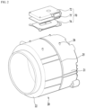
- FIG. 1 shows a laundry treatment apparatus in which the drum 30 is rotated about a rotation axis that is parallel to the ground.
- the induction module is a device for heating the drum 30.
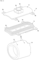
- the induction module 70 includes a base housing 74, in which a coil 71 (refer to FIGs. 3 and 4 ), which receives electric current and generates a magnetic field so that eddy current is generated at the drum, is mounted, and a module cover 72 for accommodating the base housing 74 therein.
- the coil comprises a wire through which an electric current is configured to pass so as to generate a magnetic field.
- a wire is wound to form the coil 71, and accordingly the coil 71 has a center.
- an alternating current magnetic field the direction of which varies over time.
- the alternating current magnetic field generates an induced magnetic field in a nearby conductor in a direction opposite the alternating current magnetic field, and a change in the induced magnetic field generates induced current in the conductor.
- the induced current and the induced magnetic field can be understood as a form of inertia with respect to changes in electric field and magnetic field.
- eddy current which is a type of induced current, is generated in the drum 30 due to the induced magnetic field generated in the coil 71.
- the eddy current is dissipated by the resistance of the drum 30, which is a conductor, and is converted into heat.
- the drum 30 is heated by the heat generated by the resistance, and the temperature in the drum 30 rises as the drum 30 is heated.
- the drum 30 in the case in which the drum 30 is configured as a conductor that is formed of a magnetic material such as iron (Fe), it can be heated by the alternating current of the coil 71 provided at the tub 20.
- a drum formed of stainless steel has been used in order to improve strength and hygiene.
- a stainless steel material has relatively good electric conductivity, and thus may be easily heated by a change in an electromagnetic field. This means that there is no need to specially manufacture a drum having a new configuration or a drum formed of a new material to heat the drum using the induction module 70. Therefore, a drum of the type used in a laundry treatment apparatus of the related art, i.e. a drum that is used in a laundry treatment apparatus employing a heat pump or an electric heater (a sheath heater), can also be used in a laundry treatment apparatus employing an induction module.
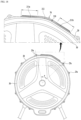
- the induction module which includes the coil 71 and the module cover 72, may be provided on the inner circumferential surface of the tub 20. Since the intensity of the magnetic field decreases with distance, it may be effective to provide the induction module on the inner circumferential surface of the tub 20 so as to narrow the gap between the induction module and the drum 30.
- the induction module it is desirable for the induction module to be provided on the outer circumferential surface of the tub 20 for safety because the tub 20 contains wash water therein and vibrates as the drum 30 rotates. Because the interior of the tub is very humid, it may be undesirable for the induction module to be provided on the inner circumferential surface of the tub in view of the insulation and stability of the coil. Therefore, as shown in FIGs. 1 and 2 , it is desirable for the induction module 70 to be provided on the outer circumferential surface of the tub 20. Also in this case, however, it is desirable that the gap between the induction module 70 and the outer circumferential surface of the drum be made as small as possible. A preferred embodiment for this will be described later.
- the tub 20 has a cylindrical shape because the drum 30 rotates to wash or dry clothes (hereinafter, referred to as 'laundry').
- the coil 71 may be provided so as to be wound around the entire outer circumferential surface of the tub 20 at least once.
- the coil 71 is wound around the entire circumference of the tub 20, it requires too much wire. In addition, a short circuit or other problems may occur due to contact between the coil and the wash water leaking from the tub 20.
- an induced magnetic field may be generated in the opening 22 in the tub 20 and the driving unit 40, and thus may fail to directly heat the outer circumferential surface of the drum 30.
- the coil 71 it is desirable for the coil 71 to be provided only on a portion of the outer circumferential surface of the tub 20. That is, the coil 71 may be provided so as to be wound around a certain region from the front side of the tub 20 to the rear side thereof at least once, rather than being wound around the entire outer circumferential surface of the tub 20.
- This configuration is determined not only in consideration of the heat generation efficiency in the drum 30, which can be achieved by the output of the induction module 70, but also in consideration of the overall manufacturing efficiency of the laundry treatment apparatus on the basis of the size of a space between the tub 20 and the cabinet 10.
- the coil 71 may be formed to have a single-layer structure. That is, the wire may be wound in a single layer, rather than in multiple layers. In the case in which the wire is wound in multiple layers, a gap is inevitably formed between adjacent portions of the wire. That is, a gap is inevitably formed between a portion of the wire that is located in the bottom layer and a portion of the wire that is located in the top layer. Therefore, the distance between the portion of the coil that is located in the top layer and the drum is increased. Of course, even if such a gap can be physically eliminated, the greater the number of layers of the coil, the longer the distance between the portion of the coil that is located in the top layer and the drum, which leads to deterioration in efficiency.
- the coil 71 it is highly desirable for the coil 71 to be formed in a single layer. This also means that it is possible to increase the contact area between the coil and the drum as much as possible while using the wire having the same length. Meanwhile, it is desirable that the coil 71 be formed so as to occupy the maximum allowable area within a given area of the base housing 72. That is, it is desirable to increase the coil density.
- the coil is formed in a manner such that the wire is wound in a closed loop. At this time, the wire must not be folded. However, it is not easy to wind the wire so that the area of the coil is maximized while preventing the wire from being folded. An embodiment capable of maximizing the area of the coil while preventing the wire from being folded sharply will be described later.
- the induction module is illustrated as being provided on the upper portion of the tub 20.
- the present invention is not limited thereto.
- the induction module may be provided on at least one of the upper portion, the lower portion, and both side portions of the tub.
- the induction module may be provided on a portion of the outer circumferential surface of the tub, and the coil 71 may be wound around the surface of the induction module that is adjacent to the tub 20 at least once within the induction module.
- the induction module directly radiates an induced magnetic field to the outer circumferential surface of the drum 30, thereby generating eddy current in the drum 30 and consequently directly heating the outer circumferential surface of the drum 30.
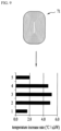
- the drum may be heated to 120 degrees Celsius or higher within a very short time by the operation of the induction module 70. If the induction module 70 is driven while the drum is in a stationary state or is rotated at a very low speed, a specific portion of the drum may be overheated very quickly. This is because heat is not sufficiently transferred from the heated drum to laundry.
- the laundry treatment apparatus includes a controller (not shown) for rotating the driving unit 40, manipulating a control panel (not shown) provided in the cabinet 10 and controlling the processes of the laundry treatment apparatus, and further includes various electric wires (not shown).
- a controller for rotating the driving unit 40, manipulating a control panel (not shown) provided in the cabinet 10 and controlling the processes of the laundry treatment apparatus, and further includes various electric wires (not shown).
- the induction module 70 serves to heat the drum 30 using the magnetic field radiated from the coil 71.
- abnormal signals may be generated in the controller and the electric wires.
- the electronic devices such as the controller, the electric wires, the control panel, etc.
- the electronic devices are susceptible to a magnetic field
- the generated magnetic field must be used only for heating the drum, it is highly desirable that the magnetic field be focused in the direction toward the drum (e.g. in the downward direction of the coil).
- the induction module 70 may further include a blocking member 77 so that the magnetic field generated by the coil 71 is focused only on the drum 30. That is, the blocking member 77 may be provided on the coil 71 so that the magnetic field is focused in the direction toward the drum.
- the blocking member 77 may be formed of a ferromagnetic material in order to focus the magnetic field generated by the coil 71 in the direction toward the drum.
- the blocking member 77 may be coupled to the upper side of the base 74, and may be attached or mounted to the inner surface of the module cover 71.
- the blocking member 77 may be formed in a flat plate shape.
- a portion of the module cover 72 may be formed of a ferromagnetic material to serve as the blocking member.
- the module cover 72 is formed in the shape of a box that has one open surface, in the case in which the module cover 72 accommodates the coil 71 or the base 74 therein, it can focus the magnetic field in the direction toward the drum 30.
- the additional blocking member 77 may be omitted.
- the blocking member 77 may be a permanent magnet such as ferrite.
- the ferrite may not be formed so as to cover the entire upper portion of the coil 71. That is, the ferrite may be formed so as to cover only a portion of the coil, like the coil-fixing portion shown in FIGs. 3 and 4 .
- the ferrite bar magnet can be fixed to the coil-fixing portion.
- a permanent magnet made of, for example, ferrite may be provided perpendicular to the longitudinal direction of the coil so as to focus the magnetic field in a desired direction. Therefore, it is possible to greatly improve efficiency using a small amount of ferrite. A concrete embodiment of the ferrite will be described later.
- the controller may adjust the amount of current that flows through the coil 71, and may supply current to the coil 71.
- the controller may further include at least one of a thermostat (not shown) or a thermistor (not shown) in order to interrupt the supply of current to the coil when an excessive amount of current is supplied to the coil or when the temperature of the coil rises above a predetermined value. That is, a temperature sensor may be included.
- the thermostat and the thermistor may be provided in any shape, as long as they can interrupt the supply of current to the coil 71.
- the permanent magnet 75 is provided to focus the magnetic field generated by the coil 71 in the direction toward the drum 30 in order to improve efficiency.
- the permanent magnet may be formed of a ferrite material.
- the permanent magnet 75 is provided in the form of a bar magnet that is perpendicular to the winding direction of the coil 71 or the longitudinal direction of the coil 71.
- the permanent magnet may be formed so as to form an intrinsic magnetic field in the upward-and-downward direction.
- the permanent magnet may be formed so that the magnetic field is formed in the direction toward the drum.
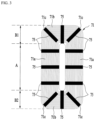
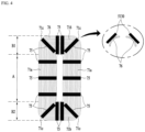
- FIGs. 3 and 4 are plan views of the coil 71 in which a wire 76 is wound around a certain region on the outer circumferential surface of the tub 20.
- the permanent magnet 75 is also illustrated as being provided on the top surface of the coil 71.
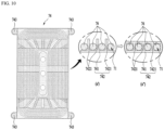
- the permanent magnet 75 may be configured as a bar magnet, and is located on the coil 71 while being arranged perpendicular to the longitudinal direction of the coil 71. This is for covering both an inner coil portion located at a radially inward position and an outer coil portion located at a radially outward position at the same time.
- the permanent magnet 75 is provided in a plural number, and the plurality of permanent magnets 75 may be bar magnets that are the same size as each other.
- the permanent magnets 75 are arranged so as to be spaced apart from each other in the longitudinal direction of the coil 71.
- the permanent magnets 75 are disposed at specific positions, the amount of the magnetic field radiated to the drum 30 is different for each portion of the circumferential surface of the drum 30, and thus it is difficult to evenly heat the drum. Therefore, in order to evenly induce the magnetic field generated by the coil 71 in the direction toward the drum 30, the permanent magnets 75 are arranged so as to be spaced apart from each other with a constant interval or a constant pattern along the circumference of the coil 71.
- the permanent magnets 75 are densely disposed on the portions of the coil 71 that are adjacent to the front and rear sides of the tub 20.
- the coil 71 may be sectioned into both end portions B1 and B2, which include a front end portion B1 located adjacent to the front side of the tub 20 and a rear end portion B2 located adjacent to the rear side of the tub 20, and an intermediate portion A, which is located between the front end portion B1 and the rear end portion B2 and has a larger area than the front end portion B1 and the rear end portion B2.
- the permanent magnets 75 may be arranged such that the number thereof disposed on the front end portion B1 or the rear end portion B2 of the coil is equal to or greater than that disposed on the intermediate portion A of the coil.
- the density of the coil 71 in the intermediate portion A is relatively large.
- the density of the coil 71 in the both end portions B1 and B2 is relatively small.
- the density of the coil is inevitably reduced in the both end portions B1 and B2 due to the rounded corners. The reason for this is that the coil cannot be theoretically bent at a right angle at the corners.
- the magnetic flux density in the both end portions B1 and B2 of the coil is increased through the dense arrangement of the permanent magnets, with the result that the drum 30 is evenly heated in the longitudinal direction thereof.
- the embodiment shown in FIG. 4 may be more efficient than the embodiment shown in FIG. 3 .
- the number of permanent magnets used for each portion of the coil is the same, it may be desirable to move the permanent magnets located in the intermediate portion A of the coil to positions adjacent to the both end portions B1 and B2 of the coil in terms of efficiency. Therefore, in the case in which the total magnetic flux density is determined through the permanent magnets, it is desirable that the magnetic flux density in the both end portions of the coil be set to be larger than the magnetic flux density in the intermediate portion of the coil.
- the above-described embodiment related to the winding form of the coil 71 and the above-described embodiment related to the arrangement of the permanent magnets 75 can be applied to a single laundry treatment apparatus without any contradiction. That is, it is possible to obtain the effect of more evenly heating the drum 30 when the above-described embodiment related to the winding form of the coil and the above-described embodiment related to the arrangement of the permanent magnets are combined, compared with when these embodiments are implemented individually.
- the coil 71 may be formed in any shape, such as a concentric circle, an ellipse, a track, etc., as long as the coil 71 can be formed on the outer circumferential surface of the tub 20 by winding the wire 76.
- the extent to which the drum 30 is heated may vary depending on the wire-winding shape. This has been described above.
- the amount of the magnetic field transferred to the center of the drum 30 and the amount of the magnetic field transferred to the front and rear sides of the drum 30 may be significantly different from each other.
- the amount of the magnetic field that is transferred to the front side of the circumferential surface of the drum 30 is relatively small.
- the area of the coil that is located near the center of the drum 30 is relatively large, the amount of the magnetic field that is transferred to the center of the circumferential surface of the drum 30 is relatively large. Therefore, it is difficult to evenly heat the drum 30.
- the coil it is desirable for the coil to be formed in a rectangular shape, rather than a square shape. That is, it is desirable that the width in the forward-and-backward direction of the coil be greater than the width in the lateral direction thereof. Accordingly, it is possible to expand the center portion of the coil, which has a relatively large area, in the direction from the center of the drum to the front and rear ends of the drum.
- the wire 76 may be wound such that the coil 71 includes straight portions 71a and 71b and a curved portion 71c.
- the inner coil portion and the outer coil portion may have the same radius of curvature as each other. That is, it is desirable that the radius of curvature of the wire at a position close to the center of the coil and the radius of curvature of the wire at a position distant from the center of the coil be the same.
- the radius of curvature in the straight portions 71a and 71b is meaningless, and thus the same radius of curvature is meaningful in the curved portion 71c. In the case of FIG.
- the radius of curvature in the curved portion 71c is different for each portion of the coil located in the radial direction. Specifically, in the case of FIG. 6 , the radius of curvature in the curved portion 71c is gradually increased in the radially outward direction.
- the straight portions 71a and 71b include a front straight portion 71b located on the front side of the outer circumferential surface of the tub 20 and a rear straight portion 71b located on the rear side of the outer circumferential surface of the tub 20, which are collectively referred to as horizontal (lateral) straight portions, and further includes a vertical (longitudinal) straight portion 71a, which is formed perpendicular to the horizontal straight portions 71b. It is desirable that the length of the vertical straight portion be greater than the length of the horizontal straight portion. That is, in the case in which the coil is formed in an elliptical shape or a track shape, it is desirable that the long axis of the coil be formed in the forward-and-backward direction of the tub.
- the curved portion 71c is formed at the position at which the horizontal straight portion 71b and the vertical straight portion 71a meet. That is, the coil may be formed by four curved portions 71c, which have the same radius of curvature as each other, and four straight portions.
- the cover 72 can be more securely fixed on the outer surface of the tub 20, and thus it is possible to prevent noise or unexpected disengagement of parts attributable to gaps between the parts even when the tub 20 vibrates.
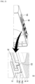
- the permanent-magnet-mounting portion 80 may further include an inner wall 81b, which protrudes downwards from the bottom surface of the cover 72 so as to be connected with the ends of the both side walls, an open surface, which is formed opposite the inner wall, and a latching portion 81a, which is formed near the open surface in order to prevent the permanent magnet 80 from being separated from the cover 72.
- a portion of the module-mounting portion 210 that faces the coil may be formed in a depressed shape.
- a portion of an inner surface of the tub that corresponds to a location of the at least one mounting portion is arranged radially closer to the rotational axis of the drum than a remaining portion of the inner surface of the tub.
- the drum 30 may be formed in a cylindrical shape in order to secure the maximum accommodation space while requiring the minimum volume when rotating. At this time, in the case in which the tub 20 also has a cylindrical shape, the interval between the outer circumferential surface of the tub 20 and the drum 30 is constant.
- the manufacture of the induction module 70 and the installation thereof on the module-mounting portion may be facilitated.
- the length of the straight region 211 may be limited in consideration of the distance from the drum 30, and the width in the circumferential direction of the induction module 70 may exceed the straight region 211.
- connection regions 212 formed at the both ends of the straight region 211 so as to be connected with the circumferential surface of the tub 20 Due to the connection regions 212 formed at the both ends of the straight region 211 so as to be connected with the circumferential surface of the tub 20, the area of the module-mounting portion 210 can be increased, and the distance from the drum 30 can be reduced.
- the induction module 70 may be located at the center of the straight region 211. Specifically, the center portion of the coil 71 of the induction module 70 may be located in a virtual plane, which includes the rotational axis of the drum 30 and is perpendicular to the straight region 211.
- the coil 71 of the induction module 70 is provided on the module-mounting portion 210 such that the center portion thereof is the closest to the drum 30 and such that the distance from the drum 30 is gradually increased from the center portion to both ends thereof.
- the distance from the center of the straight region 211 to the drum 30 is minimized, and the distance from the drums 30 is gradually increased from the center of the straight region 211 to both sides thereof.
- the magnetic field generated by the coil 71 wound in the circumferential direction of the tub 20 generates a strong induced current in the drum 30.
- the distance between the coil and the drum is constant, e.g. about 30 mm, in the circumferential direction.
- the connection regions 212 shown in FIG. 16 are curved regions that have the same curved shape as the tub. Therefore, the distance between the coil and the outer circumferential surface of the drum in the curved regions is constant, e.g. about 30 mm.
- the distance between the coil and the outer circumferential surface of the drum may vary in the range from about 24 to 30 mm.
- the distance between the coil and the outer circumferential surface of the drum at the center of the straight region may be about 24 mm, and the distance at both ends of the straight region may be about 28 mm. Therefore, the distance from the outer circumferential surface of the drum is substantially reduced in a large portion of the entire area of the coil.
- the straight region 211 in the above embodiment may be formed at the center of the module-mounting portion 210. Therefore, it is possible to further concentrate the coil at the portion corresponding to the straight region 211.
- module-mounting portion 210 on which the induction module 70 is mounted, will be described with reference to FIGs. 17 and 18 .
- structure of mounting the induction module 70 to the module-mounting portion 210 will be described.
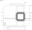
- the module-mounting portion 210 may include a first straight region 211a and a second straight region 211b in the cross-section thereof that is perpendicular to the rotational axis of the drum 30.
- the first straight region and the second straight region may be located at positions further radially inward than the reference radius of the tub.
- the first straight region and the second straight region may be considered zero gradients.
- first straight region 211a and the second straight region 211b may be connected to each other via a connection region 212.
- the connection region 212 may be formed in a curved or straight shape.
- Each of the first straight region 211a and the second straight region 211b may form a width in the circumferential direction of a rectangular-shaped surface included in the module-mounting portion 210.
- the rectangular-shaped surface is formed to facilitate the formation and the installation of the induction module 70, and is not limited to the rectangular shape.
- the module-mounting portion 210 may be formed such that at least two rectangular-shaped surfaces are connected to each other. In other words, two straight regions located at both sides may be connected to each other via a curved region located at a center portion.
- the module-mounting portion 210 may be formed by combining the straight regions and the curved region.
- the straight region 211 cannot be formed over a predetermined length in consideration of the interval between the drum 30 and the tub 20. Therefore, the module-mounting portion 210, which includes the first straight region 211a and the second straight region 211b, can form a large area in the circumferential direction without being in contact with the drum 30.
- both ends of the straight region 211 or one end of the straight region 211 may be provided outside the reference radius of the tub.
- the region provided outside the reference radius of the tub may be considered a region extending in the radial direction of the tub.
- this extending region may be only a portion for mounting the induction module on the base housing 74. That is, the coil may not be located in the extending region. This is because the coil 71 is located inside the base housing 74 so that the edges of the base housing 74 surround the coil 71. In other words, a spacing interval is provided between the coil 71 and the outermost edge of the base housing 74, and the spacing interval may be opposite the extending region.
- the length of the first straight region 211a and the length of the second straight region 211b may be equal to each other.
- the length of the straight region 211 means the distance from the drum 30. When the length is short, the distance from the drum 30 is long. Thus, it is desirable that the first straight region and the second straight region be formed symmetrical to each other. Through this configuration, it is possible to easily from the induction module and to securely fix the induction module to the module-mounting portion.
- the induction module 70 may be provided over the first straight region 211a and the second straight region 211b of the module-mounting portion 210. Specifically, both ends in the circumferential direction of the induction module 70 are located at the centers of the first straight region 211a and the second straight region 211b, and the center of the induction module 70 is located in the region to which the first straight region 211a and the second straight region 211b are connected.
- the coil 71 of the induction module 70 may be formed so as to be wound at least once between the front side of the tub 20 and the rear side thereof around the connection region 212.
- the induction module in the case in which the coil 71 is wound parallel to the module-mounting portion 71, the induction module may be located closest to the drum 30 at both ends in the circumferential direction of the tub, and the distance from the drum 30 may be gradually increased from the both ends in the circumferential direction of the tub to the center portion thereof.
- the magnetic field generated by the coil 71 wound in the axial direction of the tub 20 generates a strong induced current in the drum 30.
- the distance between the coil and the drum is constant, e.g. about 30 mm, in the circumferential direction.
- the connection region 212 shown in FIG. 18 is a curved region that has the same curved shape as the tub. Therefore, the distance between the coil and the outer circumferential surface of the drum in the curved region is constant, e.g. about 30 mm.
- the distance between the coil and the outer circumferential surface of the drum may vary in the range from about 24 to 30 mm.
- the distance between the coil and the outer circumferential surface of the drum at the center of the straight region may be about 24 mm, and the distance at both ends of the straight region may be about 26 mm. Therefore, the distance from the outer circumferential surface of the drum is substantially reduced in a large portion of the entire area of the coil.
- efficiency can be increased by reducing the distance between the coil and the outer circumferential surface of the drum by forming the module-mounting portion 210 to have a straight region in the circumferential direction of the tub.
- the straight region may be matched with the shape of the base housing forming the coil.
- the module-mounting portion and the tub may be more securely coupled to each other through the combination of the straight region and the curved region.
- the coil it has been described that it is desirable for the coil to have a hollow center portion.
- the center portion of the coil is hollow in a track shape.
- Such a hollow portion may correspond to the curved region, i.e. the connection region 212, in FIG 18 . Therefore, the portion where the coil is formed may substantially correspond to the straight region. Therefore, it is more desirable to form straight regions at the left and right portions of the module-mounting portion 210 and to form a curved region between the straight regions, i.e. at the lateral center of the module-mounting portion.
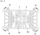
- the structure of the induction module 70 particularly the structure and position of the coupling portions 743 of the base housing 74 will be described in detail with reference to FIG. 19 .
- the induction module 70 may be formed long in the axial direction of the drum 30.
- the length of the straight region 211 of the module-mounting portion 210, on which the induction module 70 is mounted, is limited, and thus it is desirable for the induction module to evenly heat the drum 30 with a minimum area in consideration of the rotating direction of the drum 30.
- the length in the axial direction of the coil 71 may be shorter than the length of the drum 30, which can be heated, by about 20 to 40 mm.
- the coil 71 may be formed so as to be spaced apart from the front and rear sides of the drum, which can be heated, by about 10 to 20 mm.
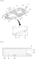
- the base housing 74 may be coupled to the outer circumferential surface of the tub 20 or the module-mounting portion 210 through the coupling portions 743, which protrude from both ends in the circumferential direction thereof and extend in the circumferential direction.
- the coupling portions 743 may be provided at both ends in the circumferential direction of the front and rear sides of the base housing 74.
- the coupling portions 743 are located at the front portion and the rear portion of the base housing 74. This arrangement position of the coupling portions 743 may effectively prevent the base housing 74 from moving in the forward-and-backward direction of the tub. However, in this case, it is not possible to effectively prevent the base housing 74 from moving in the circumferential direction of the tub.
- this embodiment proposes an example in which the coupling portions 743 protrude from both lateral sides of the base housing in the circumferential direction. That is, according to this example, the length of the base housing 74 surrounding the outer circumferential surface of the tub is further increased by the coupling portions 743.
- the base housing 74 and the module-mounting portion 210 may be formed through the combination of the straight region and the curved region on the outer circumferential surface of the tub in the circumferential direction. Therefore, the base housing 74 may be more securely coupled and fixed to the tub merely by extending the coupling portions 743 without extending the base of the base housing 74 in the circumferential direction. In other words, it is possible to more securely couple and fix the base housing by forming the coupling portions at the front end and the rear end of both sides of the base housing, rather than forming the coupling portions at both ends of the front and rear portions of the housing.
- the base housing 74 may be formed as long as possible in the axial direction while securing a space in the base housing 74 for accommodating the coil 71 therein.
- the distance between the base housing 74 and the drum 30 may be minimized by bringing the base housing 74 into close contact with the cylindrical-shaped tub 20.
- the coupling portions 743 may correspond to the straight region of the module-mounting portion 210. That is, the coupling portions and the module-mounting portion may be formed such that the horizontal surfaces thereof are in contact with each other. That is, the module-mounting portion may further include straight regions corresponding to the coupling portions 743 of the base housing, or the existing straight region of the module-mounting portion may be further extended. Through this configuration, the base housing may be more stably mounted on the module-mounting portion, which is a part of the outer circumferential surface of the tub.
- the tub 20 includes a front tub 22, which surrounds the front portion of the drum 30, a rear tub 21, which surrounds the rear portion of the drum 30, and a connecting portion 25, which connects the front tub 22 and the rear tub 21 to each other and is formed in the circumferential direction of the tub 20.
- the induction module 70 may be provided over the front tub 22 and the rear tub 21.
- the connecting portion 25 may be located at the approximate center in the forward-and-backward direction of the tub 20.
- the connecting portion 25 may be a portion that protrudes from the outer circumferential surfaces of the front tub 22 and the rear tub 21 to the greatest extent in the radial direction. In other words, since the connecting portion 25 is a portion to which the front tub 22 and the rear tub 21 are coupled, it may be extended radially outwards to increase the coupling area.
- the connecting portion 25 may be formed over the entire outer circumferential surface of the tub in the circumferential direction thereof.
- the induction module when the induction module is mounted on the outer circumferential surface of the tub, interference between the induction module and the connecting portion may occur. In order to avoid this interference, the induction module must be provided radially outside the connecting portion. Therefore, the interval between the induction module and the drum is inevitably increased.
- the connecting portion 25 may be formed so as to come into contact with the bottom surface of the base 741 of the base housing 74. That is, the connecting portion 25 may perform the same function as the reinforcing ribs 7412. Therefore, the base housing 74 may also be more securely coupled to the tub 20 through the connecting portion 25.
- the distance between the coil and the outer circumferential surface of the drum is significantly reduced due to the shape of the module-mounting portion, the structure of the connecting portion located in the module-mounting portion, and the connection structure between the base housing and the module-mounting portion, thereby greatly enhancing efficiency.
- a laundry treatment apparatus is capable of evenly drying all laundry, improving drying efficiency and shortening the drying time even when the laundry is tangled or even when the amount of laundry is large.
- a laundry treatment apparatus is capable of preventing a short circuit in a coil, which is used to heat a drum, and preventing deformation of the coil.
- a laundry treatment apparatus has a structure for cooling an overheated coil due to the inherent resistance thereof.
- a laundry treatment apparatus is capable of improving heating efficiency by increasing a coil density (a ratio of the area of the coil to the area of a base housing on which the coil is mounted).
- a laundry treatment apparatus is capable of preventing unexpected disengagement of constituent components of an induction module even when a tub vibrates by securing the coupling stability of the induction module.
- a laundry treatment apparatus is capable of preventing the occurrence of noise attributable to a gap by securing the coupling stability of the induction module.
- a laundry treatment apparatus is capable of improving drying efficiency by evenly heating the front and rear portions of a drum.
- a laundry treatment apparatus is capable of improving heating efficiency by reducing the interval between a coil of an induction module and a drum and of more stably mounting the induction module on the outer circumferential surface of a tub.
Landscapes
- Engineering & Computer Science (AREA)
- Textile Engineering (AREA)
- Physics & Mathematics (AREA)
- Electromagnetism (AREA)
- Detail Structures Of Washing Machines And Dryers (AREA)
- Main Body Construction Of Washing Machines And Laundry Dryers (AREA)
Claims (14)
- Wäschebehandlungsvorrichtung, die aufweist:einen Bottich (20);eine Trommel (30), die konfiguriert ist sich im Bottich (20) zu drehen und darin Wäsche aufzunehmen, wobei die Trommel (30) aus einem Metallmaterial ausgebildet ist; undein Induktionsmodul (70), das an einer Außenfläche des Bottichs (20) vorgesehen und konfiguriert ist, die Trommel (30) innerhalb des Bottichs (20) mittels Induktion zu erwärmen, wobei das Induktionsmodul (70) aufweist:eine Spule (71), die einen Draht aufweist, der konfiguriert ist, ein Magnetfeld zu erzeugen;ein Basisgehäuse (74), das konfiguriert ist, die Spule darin aufzunehmen, wobei das Basisgehäuse an der Außenfläche des Bottichs (20) angebracht ist; unddadurch gekennzeichnet ist, dassdas Induktionsmodul ferner aufweist:mehrere Permanentmagnete (75), die konfiguriert sind, über dem Basisgehäuse (74) angeordnet zu werden, in dem die Spule aufgenommen ist, und so angeordnet sind, um voneinander in der Längsrichtung des Drahts der Spule (71) beabstandet zu sein, wobei jeder der mehreren Permanentmagnete (75) der Länge nach senkrecht zu einer Längsrichtung des Drahts der Spule (71) angeordnet ist,die Spule (71) in einen vorderen Endabschnitt (B1), einen hinteren Endabschnitt (B2) und einen Zwischenabschnitt (A), der zwischen dem vorderen Endabschnitt (B 1) und dem hinteren Endabschnitt (B2) angeordnet ist, unterteilt ist,die mehreren Permanentmagnete (75) angeordnet sind, sodass die Permanentmagnete am vorderen Endabschnitt (B1) der Spule (71) oder am hinteren Endabschnitt (B2) der Spule (71) dichter als am Zwischenabschnitt (A) der Spule (71) angeordnet sind.
- Wäschebehandlungsvorrichtung nach Anspruch 1, wobei ein Spalt zwischen benachbarten der Permanentmagnete, die am vorderen Endabschnitt der Spule oder am hinteren Endabschnitt der Spule angeordnet sind, kleiner als ein Spalt zwischen benachbarten der Permanentmagnete ist, die am Zwischenbereich der Spule angeordnet sind.
- Wäschebehandlungsvorrichtung nach Anspruch 2, wobei die mehreren Permanentmagnete (75) mehrere Stabmagnete aufweisen, die jeweils dieselbe Größe aufweisen.
- Wäschebehandlungsvorrichtung nach Anspruch 1, wobei der vordere Endabschnitt der Spule (71) sich an einem vorderen Abschnitt des Bottichs (20) befindet und der hintere Endabschnitt der Spule (71) sich an einem hinteren Abschnitt des Bottichs (20) befindet.
- Wäschebehandlungsvorrichtung nach Anspruch 1, wobei eine Dichte der Spule im Zwischenabschnitt größer als eine Dichte der Spule im vorderen Endabschnitt oder im hinteren Endabschnitt ist, wobei die Dichte der Spule als ein Verhältnis der Fläche der Spule zur Fläche eines Basisgehäuses, an dem die Spule befestigt ist, definiert ist.
- Wäschebehandlungsvorrichtung nach Anspruch 1, wobei die Spule (71) einen geraden Abschnitt (71a, 71b) und einen gekrümmten Abschnitt (71c) aufweist, wobei der gerade Abschnitt der Spule mehrere gerade Segmente des Drahts aufweist, der innerhalb des Basisgehäuses (74) gewickelt ist, und der gekrümmte Abschnitt der Spule mehrere gekrümmte Segmente des Drahts aufweist, der innerhalb des Basisgehäuses (74) gewickelt ist.
- Wäschebehandlungsvorrichtung nach Anspruch 6, wobei der gerade Abschnitt der Spule einen vorderen geraden Abschnitt definiert, der am vorderen Endabschnitt der Spule vorgesehen ist, und einen hinteren geraden Abschnitt, der an einem hinteren Endabschnitt der Spule vorgesehen ist; und
ein gerader Zwischenabschnitt (71a) am Zwischenabschnitt der Spule vorgesehen ist und senkrecht zum vorderen oder hinteren geraden Abschnitt der Spule ist, und wobei der gekrümmte Abschnitt (71c) der Spule an einer Verbindungsstelle zwischen dem vorderen oder hinteren geraden Abschnitt (71b) und dem geraden Zwischenabschnitt (71a) ausgebildet ist. - Wäschebehandlungsvorrichtung nach Anspruch 6, wobei die mehreren Permanentmagnete (75) jeweils der Länge nach in einer Richtung angeordnet sind, die senkrecht zu einer Längsrichtung des geraden Abschnitts der Spule ist und längs einer radialen Richtung der Krümmung des gekrümmten Abschnitts der Spule verläuft.
- Wäschebehandlungsvorrichtung nach Anspruch 7, wobei der gekrümmte Abschnitt (71c) der Spule einen inneren Spulenabschnitt und einen äußeren Spulenabschnitt aufweist, und wobei der Krümmungsradius des inneren Spulenabschnitts der gleiche wie ein Krümmungsradius des äußeren Spulenabschnitts ist.
- Wäschebehandlungsvorrichtung nach einem der Ansprüche 1 bis 9, wobei das Induktionsmodul (70) ferner eine Abdeckung (72) aufweist, die konfiguriert ist, mit dem Basisgehäuse gekoppelt zu werden, um die Spule abzudecken, wobei die Abdeckung (72) mehrere Magnetbefestigungsabschnitte (81) aufweist, die konfiguriert sind, die mehreren Permanentmagnete (75) zu befestigen.
- Wäschebehandlungsvorrichtung nach Anspruch 8, wobei jeder der Befestigungsabschnitte (81) der Abdeckung (72) aufweist:zwei Seitenwände, die von einer Unterseite der Abdeckung (72) nach unten vorstehen und einen Raum dazwischen definieren, der konfiguriert ist, einen Permanentmagnet aufzunehmen; undeine untere Öffnung (82), die zwischen den beiden Seitenwänden definiert ist, durch die eine Unterseite des im Magnetbefestigungsabschnitt (81) befestigten Permanentmagneten (75) zur Spule (71) weist.
- Wäschebehandlungsvorrichtung nach Anspruch 11, wobei der Magnetbefestigungsbereich (18) eine Unterseite aufweist, die von einer der Seitenwände aus verläuft, und das Basisgehäuse (74) einen Magnetpressbereich (81c) aufweist, der in den Raum nach oben hervorsteht, der durch die untere Öffnung (82) definiert wird, um die Unterseite des Permanentmagneten zu pressen.
- Wäschebehandlungsvorrichtung nach Anspruch 10, wobei das Basisgehäuse (74) eine Befestigungsrippe (7421) aufweist, die aus dem Basisgehäuse (74) nach oben vorsteht und die einen Spulenschlitz definiert, in dem der Draht der Spule aufgenommen ist, und wobei ein unteres Ende des wenigstens einen Magnetbefestigungsabschnitts (81) in engem Kontakt mit einem oberen Ende der Befestigungsrippe (7421) steht.
- Wäschebehandlungsvorrichtung nach Anspruch 10, wobei das Basisgehäuse (74) eine Befestigungsrippe (7421) aufweist, die aus dem Basisgehäuse (74) nach oben vorsteht und die einen Spulenschlitz definiert, in dem der Draht der Spule aufgenommen ist, und wobei die Abdeckung (72) mit mehreren Verstärkungsrippen (7412) vorgesehen wird, die von einer Unterseite der Abdeckung (72) nach unten vorstehen, wobei die mehreren Verstärkungsrippen (7412) in engem Kontakt mit einem oberen Ende der Befestigungsrippe (7421) stehen.
Applications Claiming Priority (2)
| Application Number | Priority Date | Filing Date | Title |
|---|---|---|---|
| KR1020170101334A KR102499327B1 (ko) | 2017-08-09 | 2017-08-09 | 의류처리장치 |
| EP18188257.2A EP3441516B1 (de) | 2017-08-09 | 2018-08-09 | Wäschebehandlungsvorrichtung |
Related Parent Applications (1)
| Application Number | Title | Priority Date | Filing Date |
|---|---|---|---|
| EP18188257.2A Division EP3441516B1 (de) | 2017-08-09 | 2018-08-09 | Wäschebehandlungsvorrichtung |
Publications (2)
| Publication Number | Publication Date |
|---|---|
| EP3859074A1 EP3859074A1 (de) | 2021-08-04 |
| EP3859074B1 true EP3859074B1 (de) | 2025-06-25 |
Family
ID=63207622
Family Applications (2)
| Application Number | Title | Priority Date | Filing Date |
|---|---|---|---|
| EP20201504.6A Active EP3859074B1 (de) | 2017-08-09 | 2018-08-09 | Wäschebehandlungsvorrichtung mit einer induktionsheizvorrichtung |
| EP18188257.2A Active EP3441516B1 (de) | 2017-08-09 | 2018-08-09 | Wäschebehandlungsvorrichtung |
Family Applications After (1)
| Application Number | Title | Priority Date | Filing Date |
|---|---|---|---|
| EP18188257.2A Active EP3441516B1 (de) | 2017-08-09 | 2018-08-09 | Wäschebehandlungsvorrichtung |
Country Status (4)
| Country | Link |
|---|---|
| US (2) | US11001957B2 (de) |
| EP (2) | EP3859074B1 (de) |
| KR (2) | KR102499327B1 (de) |
| WO (1) | WO2019031886A1 (de) |
Families Citing this family (8)
| Publication number | Priority date | Publication date | Assignee | Title |
|---|---|---|---|---|
| KR102350079B1 (ko) * | 2017-08-09 | 2022-01-11 | 엘지전자 주식회사 | 의류처리장치 |
| KR102377042B1 (ko) * | 2017-08-09 | 2022-03-22 | 엘지전자 주식회사 | 의류처리장치 |
| US10704189B2 (en) | 2017-08-25 | 2020-07-07 | Whirlpool Corporation | Laundry appliance having an ultrasonic drying mechanism |
| US10626543B2 (en) * | 2018-05-18 | 2020-04-21 | Haier Us Appliance Solutions, Inc. | Induction heating system for a dryer appliance |
| KR102761899B1 (ko) | 2018-08-09 | 2025-02-05 | 엘지전자 주식회사 | 의류처리장치 |
| US11598042B2 (en) | 2019-03-28 | 2023-03-07 | Whirlpool Corporation | Laundry treating appliance with induction heat |
| KR20220007230A (ko) * | 2020-07-10 | 2022-01-18 | 엘지전자 주식회사 | 의류처리장치 |
| WO2022206258A1 (zh) * | 2021-04-02 | 2022-10-06 | 青岛海尔滚筒洗衣机有限公司 | 一种电磁加热模块、制造工艺及衣物处理装置 |
Family Cites Families (13)
| Publication number | Priority date | Publication date | Assignee | Title |
|---|---|---|---|---|
| US5935471A (en) | 1998-03-31 | 1999-08-10 | Camco Inc. | Heater coil support and mounting bracket |
| JP3870620B2 (ja) | 1999-09-09 | 2007-01-24 | 三菱電機株式会社 | 洗濯機 |
| JP3861731B2 (ja) | 2002-03-28 | 2006-12-20 | 松下電器産業株式会社 | 誘導加熱装置 |
| ATE460525T1 (de) * | 2006-10-19 | 2010-03-15 | Electrolux Home Prod Corp | Haushaltwaschmaschine mit induktiver heizung |
| KR101353313B1 (ko) * | 2008-02-25 | 2014-01-21 | 삼성전자주식회사 | 전기조리기기 및 이에 사용되는 유도코일유닛 |
| KR100922986B1 (ko) | 2009-01-12 | 2009-10-22 | 윤태소 | 건조기 |
| TR201005181A2 (tr) * | 2010-06-25 | 2010-12-21 | Vestel Beyaz E�Ya Sanay� Ve T�Caret Anon�M ��Rket�@ | Bir indüksiyon ısıtma sistemi |
| KR101844404B1 (ko) | 2011-03-28 | 2018-04-03 | 삼성전자주식회사 | 유도가열조리기 |
| KR101450238B1 (ko) * | 2013-08-27 | 2014-10-14 | 범일산업 주식회사 | 인덕션 가열판 및 그 제조방법 |
| DE102014208514A1 (de) * | 2014-05-07 | 2015-11-12 | BSH Hausgeräte GmbH | Wäschebehandlungsgerät mit Induktionsheizung |
| KR101596482B1 (ko) * | 2015-01-16 | 2016-03-07 | 안양섭 | 용접 예열 및 후열용 가열장치 |
| DE102016110859B3 (de) * | 2016-05-19 | 2017-06-22 | Miele & Cie. Kg | Vorrichtung zum Waschen und bzw. oder zum Trocknen von Wäsche |
| KR20180023277A (ko) * | 2016-08-25 | 2018-03-07 | 엘지전자 주식회사 | 의류처리장치 |
-
2017
- 2017-08-09 KR KR1020170101334A patent/KR102499327B1/ko active Active
-
2018
- 2018-08-09 US US16/059,286 patent/US11001957B2/en active Active
- 2018-08-09 WO PCT/KR2018/009124 patent/WO2019031886A1/en not_active Ceased
- 2018-08-09 EP EP20201504.6A patent/EP3859074B1/de active Active
- 2018-08-09 EP EP18188257.2A patent/EP3441516B1/de active Active
-
2021
- 2021-05-10 US US17/316,265 patent/US11519124B2/en active Active
-
2023
- 2023-02-08 KR KR1020230016796A patent/KR102661665B1/ko active Active
Also Published As
| Publication number | Publication date |
|---|---|
| EP3441516A1 (de) | 2019-02-13 |
| KR20190016861A (ko) | 2019-02-19 |
| US20190048509A1 (en) | 2019-02-14 |
| WO2019031886A1 (en) | 2019-02-14 |
| KR102499327B1 (ko) | 2023-02-10 |
| US11001957B2 (en) | 2021-05-11 |
| EP3441516B1 (de) | 2020-10-14 |
| US20210262144A1 (en) | 2021-08-26 |
| EP3859074A1 (de) | 2021-08-04 |
| KR102661665B1 (ko) | 2024-04-29 |
| US11519124B2 (en) | 2022-12-06 |
| KR20230022937A (ko) | 2023-02-16 |
Similar Documents
| Publication | Publication Date | Title |
|---|---|---|
| EP3913129B1 (de) | Wäschebehandlungsvorrichtung mit einer induktionsheizung | |
| EP3441515B1 (de) | Wäschebehandlungsvorrichtung | |
| US12281430B2 (en) | Laundry treatment apparatus and method of controlling the same | |
| US11519124B2 (en) | Laundry treatment apparatus and method of controlling the same | |
| US12168847B2 (en) | Clothes treatment apparatus and control method therefor | |
| KR102661666B1 (ko) | 의류처리장치 | |
| EP4155452B1 (de) | Wäschebehandlungsvorrichtung mit einer induktionsheizung | |
| CN118632955A (zh) | 衣物处理设备 |
Legal Events
| Date | Code | Title | Description |
|---|---|---|---|
| PUAI | Public reference made under article 153(3) epc to a published international application that has entered the european phase |
Free format text: ORIGINAL CODE: 0009012 |
|
| STAA | Information on the status of an ep patent application or granted ep patent |
Free format text: STATUS: REQUEST FOR EXAMINATION WAS MADE |
|
| 17P | Request for examination filed |
Effective date: 20201113 |
|
| AC | Divisional application: reference to earlier application |
Ref document number: 3441516 Country of ref document: EP Kind code of ref document: P |
|
| AK | Designated contracting states |
Kind code of ref document: A1 Designated state(s): AL AT BE BG CH CY CZ DE DK EE ES FI FR GB GR HR HU IE IS IT LI LT LU LV MC MK MT NL NO PL PT RO RS SE SI SK SM TR |
|
| RBV | Designated contracting states (corrected) |
Designated state(s): AL AT BE BG CH CY CZ DE DK EE ES FI FR GB GR HR HU IE IS IT LI LT LU LV MC MK MT NL NO PL PT RO RS SE SI SK SM TR |
|
| STAA | Information on the status of an ep patent application or granted ep patent |
Free format text: STATUS: EXAMINATION IS IN PROGRESS |
|
| 17Q | First examination report despatched |
Effective date: 20230313 |
|
| GRAP | Despatch of communication of intention to grant a patent |
Free format text: ORIGINAL CODE: EPIDOSNIGR1 |
|
| STAA | Information on the status of an ep patent application or granted ep patent |
Free format text: STATUS: GRANT OF PATENT IS INTENDED |
|
| RIC1 | Information provided on ipc code assigned before grant |
Ipc: D06F 105/28 20200101ALN20241028BHEP Ipc: D06F 103/52 20200101ALN20241028BHEP Ipc: D06F 34/24 20200101ALN20241028BHEP Ipc: D06F 58/26 20060101ALN20241028BHEP Ipc: D06F 39/04 20060101AFI20241028BHEP |
|
| GRAJ | Information related to disapproval of communication of intention to grant by the applicant or resumption of examination proceedings by the epo deleted |
Free format text: ORIGINAL CODE: EPIDOSDIGR1 |
|
| INTG | Intention to grant announced |
Effective date: 20241114 |
|
| STAA | Information on the status of an ep patent application or granted ep patent |
Free format text: STATUS: EXAMINATION IS IN PROGRESS |
|
| INTC | Intention to grant announced (deleted) | ||
| GRAS | Grant fee paid |
Free format text: ORIGINAL CODE: EPIDOSNIGR3 |
|
| STAA | Information on the status of an ep patent application or granted ep patent |
Free format text: STATUS: GRANT OF PATENT IS INTENDED |
|
| GRAP | Despatch of communication of intention to grant a patent |
Free format text: ORIGINAL CODE: EPIDOSNIGR1 |
|
| RIC1 | Information provided on ipc code assigned before grant |
Ipc: D06F 105/28 20200101ALN20250109BHEP Ipc: D06F 103/52 20200101ALN20250109BHEP Ipc: D06F 34/24 20200101ALN20250109BHEP Ipc: D06F 58/26 20060101ALN20250109BHEP Ipc: D06F 39/04 20060101AFI20250109BHEP |
|
| RIC1 | Information provided on ipc code assigned before grant |
Ipc: D06F 105/28 20200101ALN20250123BHEP Ipc: D06F 103/52 20200101ALN20250123BHEP Ipc: D06F 34/24 20200101ALN20250123BHEP Ipc: D06F 58/26 20060101ALN20250123BHEP Ipc: D06F 39/04 20060101AFI20250123BHEP |
|
| INTG | Intention to grant announced |
Effective date: 20250205 |
|
| GRAA | (expected) grant |
Free format text: ORIGINAL CODE: 0009210 |
|
| STAA | Information on the status of an ep patent application or granted ep patent |
Free format text: STATUS: THE PATENT HAS BEEN GRANTED |
|
| AC | Divisional application: reference to earlier application |
Ref document number: 3441516 Country of ref document: EP Kind code of ref document: P |
|
| AK | Designated contracting states |
Kind code of ref document: B1 Designated state(s): AL AT BE BG CH CY CZ DE DK EE ES FI FR GB GR HR HU IE IS IT LI LT LU LV MC MK MT NL NO PL PT RO RS SE SI SK SM TR |
|
| REG | Reference to a national code |
Ref country code: GB Ref legal event code: FG4D |
|
| REG | Reference to a national code |
Ref country code: CH Ref legal event code: EP |
|
| REG | Reference to a national code |
Ref country code: CH Ref legal event code: EP |
|
| REG | Reference to a national code |
Ref country code: IE Ref legal event code: FG4D |
|
| REG | Reference to a national code |
Ref country code: DE Ref legal event code: R096 Ref document number: 602018083076 Country of ref document: DE |
|
| PG25 | Lapsed in a contracting state [announced via postgrant information from national office to epo] |
Ref country code: FI Free format text: LAPSE BECAUSE OF FAILURE TO SUBMIT A TRANSLATION OF THE DESCRIPTION OR TO PAY THE FEE WITHIN THE PRESCRIBED TIME-LIMIT Effective date: 20250625 |
|
| PGFP | Annual fee paid to national office [announced via postgrant information from national office to epo] |
Ref country code: DE Payment date: 20250829 Year of fee payment: 8 |
|
| REG | Reference to a national code |
Ref country code: LT Ref legal event code: MG9D |
|
| PG25 | Lapsed in a contracting state [announced via postgrant information from national office to epo] |
Ref country code: NO Free format text: LAPSE BECAUSE OF FAILURE TO SUBMIT A TRANSLATION OF THE DESCRIPTION OR TO PAY THE FEE WITHIN THE PRESCRIBED TIME-LIMIT Effective date: 20250925 Ref country code: GR Free format text: LAPSE BECAUSE OF FAILURE TO SUBMIT A TRANSLATION OF THE DESCRIPTION OR TO PAY THE FEE WITHIN THE PRESCRIBED TIME-LIMIT Effective date: 20250926 |
|
| PG25 | Lapsed in a contracting state [announced via postgrant information from national office to epo] |
Ref country code: BG Free format text: LAPSE BECAUSE OF FAILURE TO SUBMIT A TRANSLATION OF THE DESCRIPTION OR TO PAY THE FEE WITHIN THE PRESCRIBED TIME-LIMIT Effective date: 20250625 |
|
| PG25 | Lapsed in a contracting state [announced via postgrant information from national office to epo] |
Ref country code: HR Free format text: LAPSE BECAUSE OF FAILURE TO SUBMIT A TRANSLATION OF THE DESCRIPTION OR TO PAY THE FEE WITHIN THE PRESCRIBED TIME-LIMIT Effective date: 20250625 |
|
| PG25 | Lapsed in a contracting state [announced via postgrant information from national office to epo] |
Ref country code: RS Free format text: LAPSE BECAUSE OF FAILURE TO SUBMIT A TRANSLATION OF THE DESCRIPTION OR TO PAY THE FEE WITHIN THE PRESCRIBED TIME-LIMIT Effective date: 20250925 |
|
| PG25 | Lapsed in a contracting state [announced via postgrant information from national office to epo] |
Ref country code: LV Free format text: LAPSE BECAUSE OF FAILURE TO SUBMIT A TRANSLATION OF THE DESCRIPTION OR TO PAY THE FEE WITHIN THE PRESCRIBED TIME-LIMIT Effective date: 20250625 |
|
| REG | Reference to a national code |
Ref country code: NL Ref legal event code: MP Effective date: 20250625 |
|
| PG25 | Lapsed in a contracting state [announced via postgrant information from national office to epo] |
Ref country code: NL Free format text: LAPSE BECAUSE OF FAILURE TO SUBMIT A TRANSLATION OF THE DESCRIPTION OR TO PAY THE FEE WITHIN THE PRESCRIBED TIME-LIMIT Effective date: 20250625 |
|
| PG25 | Lapsed in a contracting state [announced via postgrant information from national office to epo] |
Ref country code: PT Free format text: LAPSE BECAUSE OF FAILURE TO SUBMIT A TRANSLATION OF THE DESCRIPTION OR TO PAY THE FEE WITHIN THE PRESCRIBED TIME-LIMIT Effective date: 20251027 |
|
| REG | Reference to a national code |
Ref country code: AT Ref legal event code: MK05 Ref document number: 1806534 Country of ref document: AT Kind code of ref document: T Effective date: 20250625 |
|
| PG25 | Lapsed in a contracting state [announced via postgrant information from national office to epo] |
Ref country code: IS Free format text: LAPSE BECAUSE OF FAILURE TO SUBMIT A TRANSLATION OF THE DESCRIPTION OR TO PAY THE FEE WITHIN THE PRESCRIBED TIME-LIMIT Effective date: 20251025 |
|
| PG25 | Lapsed in a contracting state [announced via postgrant information from national office to epo] |
Ref country code: AT Free format text: LAPSE BECAUSE OF FAILURE TO SUBMIT A TRANSLATION OF THE DESCRIPTION OR TO PAY THE FEE WITHIN THE PRESCRIBED TIME-LIMIT Effective date: 20250625 Ref country code: SM Free format text: LAPSE BECAUSE OF FAILURE TO SUBMIT A TRANSLATION OF THE DESCRIPTION OR TO PAY THE FEE WITHIN THE PRESCRIBED TIME-LIMIT Effective date: 20250625 |
|
| PG25 | Lapsed in a contracting state [announced via postgrant information from national office to epo] |
Ref country code: CZ Free format text: LAPSE BECAUSE OF FAILURE TO SUBMIT A TRANSLATION OF THE DESCRIPTION OR TO PAY THE FEE WITHIN THE PRESCRIBED TIME-LIMIT Effective date: 20250625 |
|
| PG25 | Lapsed in a contracting state [announced via postgrant information from national office to epo] |
Ref country code: PL Free format text: LAPSE BECAUSE OF FAILURE TO SUBMIT A TRANSLATION OF THE DESCRIPTION OR TO PAY THE FEE WITHIN THE PRESCRIBED TIME-LIMIT Effective date: 20250625 |
|
| PG25 | Lapsed in a contracting state [announced via postgrant information from national office to epo] |
Ref country code: EE Free format text: LAPSE BECAUSE OF FAILURE TO SUBMIT A TRANSLATION OF THE DESCRIPTION OR TO PAY THE FEE WITHIN THE PRESCRIBED TIME-LIMIT Effective date: 20250625 |
|
| PG25 | Lapsed in a contracting state [announced via postgrant information from national office to epo] |
Ref country code: SK Free format text: LAPSE BECAUSE OF FAILURE TO SUBMIT A TRANSLATION OF THE DESCRIPTION OR TO PAY THE FEE WITHIN THE PRESCRIBED TIME-LIMIT Effective date: 20250625 |
|
| PG25 | Lapsed in a contracting state [announced via postgrant information from national office to epo] |
Ref country code: ES Free format text: LAPSE BECAUSE OF FAILURE TO SUBMIT A TRANSLATION OF THE DESCRIPTION OR TO PAY THE FEE WITHIN THE PRESCRIBED TIME-LIMIT Effective date: 20250625 |
|
| PG25 | Lapsed in a contracting state [announced via postgrant information from national office to epo] |
Ref country code: RO Free format text: LAPSE BECAUSE OF FAILURE TO SUBMIT A TRANSLATION OF THE DESCRIPTION OR TO PAY THE FEE WITHIN THE PRESCRIBED TIME-LIMIT Effective date: 20250625 |
|
| REG | Reference to a national code |
Ref country code: CH Ref legal event code: H13 Free format text: ST27 STATUS EVENT CODE: U-0-0-H10-H13 (AS PROVIDED BY THE NATIONAL OFFICE) Effective date: 20260324 |
|
| PG25 | Lapsed in a contracting state [announced via postgrant information from national office to epo] |
Ref country code: MC Free format text: LAPSE BECAUSE OF FAILURE TO SUBMIT A TRANSLATION OF THE DESCRIPTION OR TO PAY THE FEE WITHIN THE PRESCRIBED TIME-LIMIT Effective date: 20250625 |
|
| PG25 | Lapsed in a contracting state [announced via postgrant information from national office to epo] |
Ref country code: DK Free format text: LAPSE BECAUSE OF FAILURE TO SUBMIT A TRANSLATION OF THE DESCRIPTION OR TO PAY THE FEE WITHIN THE PRESCRIBED TIME-LIMIT Effective date: 20250625 |
|
| PG25 | Lapsed in a contracting state [announced via postgrant information from national office to epo] |
Ref country code: LU Free format text: LAPSE BECAUSE OF NON-PAYMENT OF DUE FEES Effective date: 20250809 Ref country code: IT Free format text: LAPSE BECAUSE OF FAILURE TO SUBMIT A TRANSLATION OF THE DESCRIPTION OR TO PAY THE FEE WITHIN THE PRESCRIBED TIME-LIMIT Effective date: 20250625 |
|
| PG25 | Lapsed in a contracting state [announced via postgrant information from national office to epo] |
Ref country code: CH Free format text: LAPSE BECAUSE OF NON-PAYMENT OF DUE FEES Effective date: 20250831 |
|
| PLBE | No opposition filed within time limit |
Free format text: ORIGINAL CODE: 0009261 |
|
| STAA | Information on the status of an ep patent application or granted ep patent |
Free format text: STATUS: NO OPPOSITION FILED WITHIN TIME LIMIT |