EP4155452B1 - Wäschebehandlungsvorrichtung mit einer induktionsheizung - Google Patents
Wäschebehandlungsvorrichtung mit einer induktionsheizung Download PDFInfo
- Publication number
- EP4155452B1 EP4155452B1 EP22201833.5A EP22201833A EP4155452B1 EP 4155452 B1 EP4155452 B1 EP 4155452B1 EP 22201833 A EP22201833 A EP 22201833A EP 4155452 B1 EP4155452 B1 EP 4155452B1
- Authority
- EP
- European Patent Office
- Prior art keywords
- drum
- tub
- coil
- induction module
- module
- Prior art date
- Legal status (The legal status is an assumption and is not a legal conclusion. Google has not performed a legal analysis and makes no representation as to the accuracy of the status listed.)
- Active
Links
Images

















Classifications
-
- D—TEXTILES; PAPER
- D06—TREATMENT OF TEXTILES OR THE LIKE; LAUNDERING; FLEXIBLE MATERIALS NOT OTHERWISE PROVIDED FOR
- D06F—LAUNDERING, DRYING, IRONING, PRESSING OR FOLDING TEXTILE ARTICLES
- D06F39/00—Details of washing machines not specific to a single type of machines covered by groups D06F9/00 - D06F27/00
- D06F39/04—Heating arrangements
-
- D—TEXTILES; PAPER
- D06—TREATMENT OF TEXTILES OR THE LIKE; LAUNDERING; FLEXIBLE MATERIALS NOT OTHERWISE PROVIDED FOR
- D06F—LAUNDERING, DRYING, IRONING, PRESSING OR FOLDING TEXTILE ARTICLES
- D06F34/00—Details of control systems for washing machines, washer-dryers or laundry dryers
- D06F34/08—Control circuits or arrangements thereof
-
- D—TEXTILES; PAPER
- D06—TREATMENT OF TEXTILES OR THE LIKE; LAUNDERING; FLEXIBLE MATERIALS NOT OTHERWISE PROVIDED FOR
- D06F—LAUNDERING, DRYING, IRONING, PRESSING OR FOLDING TEXTILE ARTICLES
- D06F34/00—Details of control systems for washing machines, washer-dryers or laundry dryers
- D06F34/14—Arrangements for detecting or measuring specific parameters
-
- D—TEXTILES; PAPER
- D06—TREATMENT OF TEXTILES OR THE LIKE; LAUNDERING; FLEXIBLE MATERIALS NOT OTHERWISE PROVIDED FOR
- D06F—LAUNDERING, DRYING, IRONING, PRESSING OR FOLDING TEXTILE ARTICLES
- D06F58/00—Domestic laundry dryers
- D06F58/20—General details of domestic laundry dryers
- D06F58/26—Heating arrangements, e.g. gas heating equipment
-
- D—TEXTILES; PAPER
- D06—TREATMENT OF TEXTILES OR THE LIKE; LAUNDERING; FLEXIBLE MATERIALS NOT OTHERWISE PROVIDED FOR
- D06F—LAUNDERING, DRYING, IRONING, PRESSING OR FOLDING TEXTILE ARTICLES
- D06F2103/00—Parameters monitored or detected for the control of domestic laundry washing machines, washer-dryers or laundry dryers
- D06F2103/24—Spin speed; Drum movements
-
- D—TEXTILES; PAPER
- D06—TREATMENT OF TEXTILES OR THE LIKE; LAUNDERING; FLEXIBLE MATERIALS NOT OTHERWISE PROVIDED FOR
- D06F—LAUNDERING, DRYING, IRONING, PRESSING OR FOLDING TEXTILE ARTICLES
- D06F2103/00—Parameters monitored or detected for the control of domestic laundry washing machines, washer-dryers or laundry dryers
- D06F2103/28—Air properties
- D06F2103/32—Temperature
-
- D—TEXTILES; PAPER
- D06—TREATMENT OF TEXTILES OR THE LIKE; LAUNDERING; FLEXIBLE MATERIALS NOT OTHERWISE PROVIDED FOR
- D06F—LAUNDERING, DRYING, IRONING, PRESSING OR FOLDING TEXTILE ARTICLES
- D06F2103/00—Parameters monitored or detected for the control of domestic laundry washing machines, washer-dryers or laundry dryers
- D06F2103/52—Parameters monitored or detected for the control of domestic laundry washing machines, washer-dryers or laundry dryers related to electric heating means, e.g. temperature or voltage
-
- D—TEXTILES; PAPER
- D06—TREATMENT OF TEXTILES OR THE LIKE; LAUNDERING; FLEXIBLE MATERIALS NOT OTHERWISE PROVIDED FOR
- D06F—LAUNDERING, DRYING, IRONING, PRESSING OR FOLDING TEXTILE ARTICLES
- D06F2105/00—Systems or parameters controlled or affected by the control systems of washing machines, washer-dryers or laundry dryers
- D06F2105/28—Electric heating
-
- D—TEXTILES; PAPER
- D06—TREATMENT OF TEXTILES OR THE LIKE; LAUNDERING; FLEXIBLE MATERIALS NOT OTHERWISE PROVIDED FOR
- D06F—LAUNDERING, DRYING, IRONING, PRESSING OR FOLDING TEXTILE ARTICLES
- D06F25/00—Washing machines with receptacles, e.g. perforated, having a rotary movement, e.g. oscillatory movement, the receptacle serving both for washing and for centrifugally separating water from the laundry and having further drying means, e.g. using hot air
-
- D—TEXTILES; PAPER
- D06—TREATMENT OF TEXTILES OR THE LIKE; LAUNDERING; FLEXIBLE MATERIALS NOT OTHERWISE PROVIDED FOR
- D06F—LAUNDERING, DRYING, IRONING, PRESSING OR FOLDING TEXTILE ARTICLES
- D06F34/00—Details of control systems for washing machines, washer-dryers or laundry dryers
- D06F34/14—Arrangements for detecting or measuring specific parameters
- D06F34/26—Condition of the drying air, e.g. air humidity or temperature
-
- D—TEXTILES; PAPER
- D06—TREATMENT OF TEXTILES OR THE LIKE; LAUNDERING; FLEXIBLE MATERIALS NOT OTHERWISE PROVIDED FOR
- D06F—LAUNDERING, DRYING, IRONING, PRESSING OR FOLDING TEXTILE ARTICLES
- D06F37/00—Details specific to washing machines covered by groups D06F21/00 - D06F25/00
- D06F37/26—Casings; Tubs
- D06F37/267—Tubs specially adapted for mounting thereto components or devices not provided for in preceding subgroups
-
- D—TEXTILES; PAPER
- D06—TREATMENT OF TEXTILES OR THE LIKE; LAUNDERING; FLEXIBLE MATERIALS NOT OTHERWISE PROVIDED FOR
- D06F—LAUNDERING, DRYING, IRONING, PRESSING OR FOLDING TEXTILE ARTICLES
- D06F58/00—Domestic laundry dryers
- D06F58/02—Domestic laundry dryers having dryer drums rotating about a horizontal axis
- D06F58/04—Details
Definitions
- the present invention relates to a laundry treatment apparatus, and more specifically to a laundry treatment apparatus in which a drum for receiving a laundry is directly heated.
- laundry treatment apparatuses are apparatuses for treating laundry, specifically, for washing, drying or refreshing laundry.
- washing machine mainly adapted to wash laundry
- drying machine mainly adapted to dry laundry
- refresher mainly adapted to refresh laundry
- a laundry treatment apparatus that can perform at least two laundry-treating processes, among washing, drying and refreshing, in a single body.
- a combined washing and drying machine is a kind of laundry treatment apparatus that can perform all of washing, drying and refreshing in a single body.
- a laundry treatment apparatus may be provided with a heating device for heating wash water or air.
- the reason for heating wash water to increase the temperature thereof is to promote activation of detergent and breakdown of dirt in order to improve washing performance.
- the reason for heating air is to evaporate moisture by applying heat to wet laundry in order to dry laundry.
- wash water is heated by an electric heater, which is mounted to a tub in which wash water is contained.
- the electric heater is immersed in wash water, which contains foreign substances or detergent.
- foreign substances such as scale may accumulate on the electric heater, which may lead to deterioration in the performance of the electric heater.
- a module-mounted portion is formed on an outer circumferential face of the tub, wherein the induction module is mounted on the module-mounted portion.
- the base housing may be coupled to the module-mounted portion in a conformed manner. In this way, the induction module can be more stably coupled to the tub outer circumferential face.
- the module-mounted portion includes a flat portion positioned more radially inwardly than an outer circumferential face of the tub.
- the flat portion may define an inner portion of the module-mounted portion.
- the flat portion may define an outer portion of the module-mounted portion.
- the tub may include a front tub, a rear tub, and a tub connector connecting the front tub and the rear tub, wherein the tub connector extends radially outwardly, wherein the base housing is in close contact with a top of the tub connector.
- the reinforcing ribs may protrude downwards from a bottom of the base housing and maintain a spacing between the base housing and the outer circumferential face of the tub.
- Each coil slot may define a coil receiving portion defined between adjacent fixing ribs.
- a spacing between the adjacent fixing ribs may be set to be smaller than a diameter of each wire, wherein each wire is press-fitted into each coil slot.
- a protrusion height of the fixing rib may be set to be larger than a diameter of each wire, wherein after each wire is inserted into each coil slot, a top of each fixing rib is melted to cover a top of each wire.
- the coil may form a single layer.
- the coil may have a track shape with a long axis extending in a front-rear direction of the drum.
- the coil may have two front-rear directional straight portions and two left-right directional straight portions, and has four curved portions between the two front-rear directional straight portions and two left-right directional straight portions, wherein a radius of curvature of each of the curved portions in an radially innermost wire is equal to a radius of curvature of each of the curved portions in an radially outermost wire.
- a laundry treatment apparatus comprising: a tub; a drum rotatably disposed inside the tub for receiving laundry therein, wherein the drum is made of a metal material; and an induction module disposed on the tub to be spaced from a circumferential surface of the drum for generating an electromagnetic field to heat the circumferential surface of the drum, wherein the induction module includes: a coil formed of windings of wires, wherein the coil generates a magnetic field when an electric current is applied thereto; and a base housing mounted on an outer circumferential face of the tub, wherein the base housing receives the coil, wherein the coil has a straight portion and a curved portion, wherein a radius of curvature of an outer wire in a curved portion is equal to a radius of curvature of an inner wire in a curved portion.
- a laundry treatment apparatus comprising: a tub; a drum rotatably disposed inside the tub for receiving laundry therein, wherein the drum is made of a metal material; and an induction module disposed on the tub to be spaced from a circumferential surface of the drum for generating an electromagnetic field to heat the circumferential surface of the drum, wherein the induction module includes: a coil formed of windings of wires, wherein the coil generates a magnetic field when an electric current is applied thereto; a base housing mounted on an outer circumferential face of the tub, wherein the base housing receives the coil, and permanent magnets disposed on the coil to direct the magnetic field generated from the coil toward the drum, wherein each of the permanent magnets is oriented to be perpendicular to a length direction of the coil.
- a laundry treatment apparatus includes a cylindrical tub installed inside the cabinet and having a receiving space defined therein; a metal drum which is rotatably installed in the tub and accommodates laundry; and an induction module for inductively heating the drum via forming a magnetic field, wherein the induction module is mounted on a module-mounted portion formed on an outer circumferential face of the tub, wherein the module-mounted portion is positioned more radially inwardly than an outer circumferential face of the tub.
- the module-mounted portion may be formed by flattening a portion of the curved outer circumferential face of the tub. That is, a module-mounted portion may be formed by converting at least a portion of the curved face of the tub to a flat face. Moreover, a distance between the flat portion and the center of the cross section of the tub is smaller than a distance between the curved face of the tub and the center of the tub.
- a laundry treatment apparatus comprising: a tub; a drum rotatably disposed inside the tub for receiving laundry therein, wherein the drum is made of a metal material; and an induction module disposed on the tub to be spaced from a circumferential surface of the drum for generating an electromagnetic field to heat the circumferential surface of the drum, wherein the induction module includes: a coil formed of windings of wires, wherein the coil generates a magnetic field when an electric current is applied thereto; a base housing mounted on an outer circumferential face of the tub, wherein the base housing has coil slots defined therein for receiving the wires, wherein a width of each coil slot may be set to be smaller than a diameter of each wire, wherein each wire is press-fitted into each coil slot; and a module cover coupled with the base housing for covering the coil.
- a laundry treatment apparatus comprising: a drum made of a metal material and adapted to receive laundry therein; an induction module spaced apart from the circumferential surface of the drum, wherein the induction module heats the circumferential surface of the drum through a magnetic field generated by applying a current to a coil of the induction module; a lifter installed inside the drum to move the laundry when the lifter rotates inside the drum; and a module controller for controlling an output of the induction module to control an amount of a heat generated from the circumference face of the drum, wherein the module controller controls a amount of a heat differently based on a change in a position of the lifter as the drum rotates.
- the module controller may preferably control the output of the induction module so that the amount of heat generated by the drum when the lifter is not shortest to the induction module is greater than the amount of heat generated by the drum when the lifter is shortest to the induction module.
- the module controller reduces the output of the induction module to zero or a value below a normal state output when the lifter is shortest to the induction module, and control the output of the induction module to the normal state output when the lifter is not shortest to the induction module.
- the lifter may be mounted on the inner circumference of the drum.
- the lifter may be made of a plastic material.
- the apparatus may include a magnet provided on the drum such that a position thereof relative to the lifter is fixed; and a sensor disposed in a fixed position outside the drum, wherein the sensor senses a change of the position of the magnet as the drum rotates and senses the position of the lifter.
- such a configuration may estimate the position of the lifter in a predetermined angle relationship with the magnet position by sensing the position of the magnet.
- the sensor may include a reed switch or hall sensor that outputs different signals or flags depending on whether the magnet is detected.
- the magnet may be disposed in the drum, and the sensor may be provided in the tub.
- the sensor may be mounted at the tub portion opposite the tub portion where the induction module is mounted, to minimize the effect of the magnetic field generated by the induction module.
- the apparatus may include a main controller for controlling driving of a motor for rotating the drum.
- the main controller may be configured to communicate with the module controller.
- the plurality of the lifters may be arranged along the circumferential direction of the drum.
- the magnet may include the same number magnets as the number of the lifters.
- the sensor senses a position of each magnet, and senses a position of each lifter, and delivers the sensed result to the module controller.
- three magnets may be provided when three lifters are provided.
- the lifters and the magnets may be arranged in the same angular spacing. Therefore, when one magnet is detected, the position of the nearby lifter may be estimated. This may allow estimating each lifter position relatively accurately even when the drum RPM varies.
- the magnet may be singular regardless of the number of the lifters.
- the sensor senses the position of the magnet, senses the position of a specific lifter, and transmits the sensed output to the module controller.
- the main controller may be configured to estimate the positions of the remaining lifters based on the output from the sensor and the rotation angle of the motor.
- this approach may be economical to reduce the number of magnets. Estimating the position of one of the lifters via the magnet may lead to estimating the position of the remaining lifters relatively accurately by considering the current RPM and the angular spacing between the adjacent lifters. However, it may be difficult to estimate the relative positions of the lifters under the variable RPM of the drum.
- a repeated embossing pattern may be formed along the circumference.
- the formation of the embossing pattern may be excluded on a portion of the circumference of the drum on which the lifter is mounted.
- the embossing pattern may be formed by protrusions or depressions from or into the circumference face portion of the drum. Therefore, an area facing the induction module in a region where the embossing pattern is formed is smaller than an area facing the induction module in a region where the embossing pattern is not formed, and a spacing between the former region and the induction module may be larger than a spacing between the latter region and the induction module. Therefore, the current flowing in the induction module or the output (power) of the induction module may become relatively large at the time when the embossing pattern faces the induction module at a shortest distance.
- an area facing the induction module in a region where the embossing pattern is not formed, that is, a region on which the lifter is mounted may be relatively larger.
- the spacing between the lifter region and the induction module may be smaller.
- the value of the current flowing in the induction module or the output of the induction module may be relatively smaller when the lifter region faces the induction module at a shortest distance.
- the embossing pattern and the lifter mounted portion may be arranged alternately and repeatedly and regularly along the circumference of the drum. Therefore, the controller may estimate the position of the lifter based on the change in the current or output of the induction module according to the rotation angle of the drum. That is, the position of the lifter can be estimated relatively accurately even when a separate sensor for sensing the rotation angle of the drum is not provided.
- the module controller may be configured to estimate the position of the lifter based on the change of the power or current of the induction module due to the presence or absence of a shortest-distance facing between the embossing pattern and the induction module.
- the module controller itself, which controls the output of the induction module, can estimate the position of the lifter by receiving the change of the output of the induction module as feed-back information.
- a method for controlling a laundry treatment apparatus may include a drum made of a metal material and adapted to receive laundry therein; an induction module spaced apart from the circumferential surface of the drum, wherein an induction module heats the circumferential surface of the drum using a magnetic field generated by applying a current to a coil of the induction module; a lifter installed inside the drum to move laundry when the lifter rotates inside the drum; and a module controller that controls the output of the induction module to control the amount of heat generated from the circumference of the drum, wherein the method may include operating the induction module; controlling, by the module controller, an output of the induction module to a normal state output; sensing a position of the lifter; and when the position of the lifter is detected, reducing, by the module controller, the output of the induction module.
- the method may include determining a condition about whether to perform the reduction phase of the output of the induction module, regardless of whether the lifter position is detected or not.
- a factor for the condition may include a rotational speed of the drum, or a current cycle type.
- the rotational speed of the drum When the rotational speed of the drum is higher than or equal to a spin speed, which is higher than a tumbling speed, the laundry will rotate while contacting closely the inner circumference of the drum.
- the tumbling speed is a speed at which the laundry may fall down after the laundry has been lifted up by the lifter as the drum is rotated.
- the centrifugal force becomes larger than the gravitational acceleration, so that laundry does not fall down but closely adheres to the inner surface of the drum and rotates integrally with the drum.
- the condition determination phase may be configured such that, when the rotational speed of the drum is lower than or equal to a predetermined speed, the reduction phase of the output of the induction module may performed. When the rotation speed of the drum exceeds the predetermined speed, the decreasing phase of the output of the induction module may not be performed.
- the predetermined speed may be 200 RPM in one example.
- the laundry treatment apparatus includes a tub that houses the drum and stores washing-water therein, wherein the output reducing phase is not performed when in the condition determining phase, a washing cycle when the laundry is stored in the tub is determined.
- the washing cycle For the washing cycle, a portion of the circumferential surface of the drum is immersed in the washing-water inside the tub. Therefore, when the drum rotates, the heat generated from the drum may be transferred to the washing-water very effectively. Therefore, for the washing cycle, the output reduction of the induction module may not be necessary.
- the output reduction phase is preferably performed.
- the method may further include sensing the current value flowing in the induction module or the power or output of the induction module.
- the position sensing of the lifter may include estimating the position of the lifter based on a change in the current value or power as sensed. In this case, a separate sensor is not required, which is very economical.
- the apparatus may include a magnet provided on the drum such that a position thereof relative to the lifter is fixed; and a sensor disposed in a fixed position outside the drum, wherein the sensor senses a change of the position of the magnet as the drum rotates and senses the position of the lifter.
- the position sensing of the lifter may include sensing the position of the lifter based on the output value from the sensor.
- the plurality of the lifters may be arranged along the circumferential direction of the drum.
- the laundry treatment apparatus includes a single magnet such that a position thereof relative to the lifter is fixed; and a sensor disposed in a fixed position outside the drum, wherein the sensor senses a change of the position of the magnet as the drum rotates and senses the position of a specific lifter.
- the position sensing of the lifter may include sensing the position of the specific lifter according to the output value of the sensor, and estimating positions of the remaining lifters based on the rotation angle of the drum or the rotation angle of the motor driving the drum.
- the output reduction phase may be performed.
- the output of the induction module may be controlled to be variable after the induction module is operated. That is, the output may be variable after the induction module operates in the normal state output mode.
- the induction module heats only a specific portion of the drum.
- the drum needs to be rotated to prevent overheating of the drum. That is, it is preferable to rotate the drum to vary a portion of the drum being heated.
- the drum be rotated before the induction module operates.
- the rotational speed of the drum is generally set to a rotational speed allowing the tumbling driving.
- the drum accelerates to a speed allowing the tumbling driving immediately after the drum stops.
- the tumbling drive may be achieved by forward and reverse rotations. That is, after the tumbling driving of the drum is continued in the clockwise direction, the drum may be stopped and then may be tumbled driven in the counterclockwise direction again.
- the certain part of the drum may also overheat.
- the tumbling driving speed is 40 RPM
- the tumbling drive of the drum may be performed in a predetermined direction, and then the drum may be stopped again and then the tumbling drive of the drum may be performed in an opposite direction.
- the induction module is operated after the drum starts to rotate and before the drum RPM reaches the normal tumbling RPM.
- the induction module can be activated after the drum RPM reaches the tumbling RPM.
- the induction module may be activated when the drum RPM is greater than 30 RPM. Moreover, when the drum RPM is lower than 30 RPM, the induction module may be disabled.
- the induction module may be driven after the drum rotation starts and may be stopped before the drum rotation is stopped. That is, the induction module may be turned on/off based on a preset RPM lower than a normal tumbling RPM.
- the apparatus may include a tub; a drum rotatably disposed inside the tub for receiving laundry therein, wherein the drum is made of a metal material; and an induction module disposed on the tub to be spaced from a circumferential surface of the drum for generating an electromagnetic field to heat the circumferential surface of the drum; a lifter installed inside the drum to move laundry when the lifter rotates inside the drum; a temperature sensor adapted to sense the temperature of the drum; and a module controller configured for controlling an output of the induction module to control the amount of heat generated on the circumference of the drum, wherein the module controller is configured to control the amount of the heat based on the temperature sensed by the temperature sensor.
- the induction module may be mounted in either the first or second quadrant of the cross-section of the tub or in the first and second quadrants thereof.
- the module controller preferably turns off the driving of the induction module when the temperature of the drum is greater than a predetermined temperature based on the temperature sensed by the temperature sensor.
- a method for controlling a laundry treatment apparatus may include a tub; a drum rotatably disposed inside the tub for receiving laundry therein, wherein the drum is made of a metal material; and an induction module disposed on the tub to be spaced from a circumferential surface of the drum for generating an electromagnetic field to heat the circumferential surface of the drum; a lifter installed inside the drum to move laundry when the lifter rotates inside the drum; a temperature sensor adapted to sense the temperature of the drum; and a module controller configured for controlling an output of the induction module to control the amount of heat generated on the circumference of the drum, wherein the module controller is configured to control the amount of the heat based on the temperature sensed by the temperature sensor, wherein the method may include operating the induction module; controlling an output of the induction module to the normal state output by the module controller; sensing the temperature of the drum by the temperature sensor; and reducing the output of the induction module by the module controller when the temperature of the
- the predetermined RPM may be preferably greater than 0 RPM and lower than the tumbling RPM.
- the present disclosure provides a laundry treatment apparatus in which even when laundry is not completely immersed in washing-water, the laundry can be steeped with the water or sterilized.
- the present disclosure provides a laundry treatment apparatus in which even when laundry gets tangled or is massive, the laundry can be dried entirely and evenly and a drying efficiency can be improved.
- the present disclosure may provide a laundry treatment apparatus in which an electrical current leakage or short circuit to a coil is suppressed even when the drum is heated by the coil, and the coil is prevented from being deformed.
- the present disclosure may provide a laundry treatment apparatus in which the coil can be structurally cooled even when the coil is heated due to its own resistance.
- the present disclosure may provide a laundry treatment apparatus which improves a drying efficiency by uniformly heating front and rear faces of the drum.
- the present disclosure may provide a laundry treatment apparatus which may effectively prevent overheat which may otherwise occur at a lifter provided on the drum, thereby improving a safety.
- the present disclosure may provide a laundry treatment apparatus and a method for controlling the laundry treatment apparatus in which a basic function of the lifter is faithfully maintained and a stability is improved.
- the present disclosure may provide a laundry treatment apparatus and a method for controlling the laundry treatment apparatus in which overheating of a part of the drum on where the lifter is mounted is suppressed without changing shapes of the drum and the lifter.
- the present disclosure may provide a laundry treatment apparatus and a method for controlling the laundry treatment apparatus in which detecting a position of the lifter, and reducing an amount of heat generated at a portion at an circumferential surface of the drum corresponding to the lifter position may lead to reducing an energy loss and preventing the lifter from being damaged.
- the present disclosure may provide a laundry treatment apparatus in which the drum and the lifter are heated so that a space where the laundry is received can be heated evenly.
- the present disclosure may provide a laundry treatment apparatus and a method for controlling the laundry treatment apparatus in which the overheating of the lifter may be suppressed by allowing a heating temperature of a portion of the drum on which the lifter is mounted to be lower than that of a portion of the drum where the lifter is not mounted, and the heat transfer through the lifter is allowed to improve the heating efficiency.
- a laundry treatment apparatus may include a cabinet 10 forming the external appearance of the laundry treatment apparatus.
- a laundry treatment apparatus according to the invention includes a tub 20, a drum 30, and an induction module 70 for heating the drum 30.
- the tub 20 may be provided in the cabinet 10 to accommodate the drum therein.
- the tub may be provided in the front side thereof with an opening.
- the drum 30 is rotatably provided in the tub to contain laundry therein.
- the drum may be provided in the front side thereof with an opening. Laundry can be introduced into the drum through the openings in the tub and the drum.
- the induction module 70 is configured to generate an electromagnetic field to heat the drum.
- the induction module 70 may be provided on the outer surface of the tub 20.
- the induction module 70 may be provided on the outer circumferential of the tub 20.
- the tub 20 provides a certain accommodation space and has an opening formed in the front side thereof.
- the drum 30 is rotatably installed in the accommodation space in the tub 20 in order to contain laundry therein, and is formed of a conductive material.
- the induction module is disposed on the outer circumferential surface of the tub 20 to heat the drum 30 using an electromagnetic field.
- the laundry treatment apparatus may further include a driving unit 40 configured to drive the drum 30 so that the drum 30 rotates inside the tub 20.
- the driving unit 40 includes a motor 41, and the motor includes a stator and a rotor.
- the rotor is connected to a rotary shaft 42, and the rotary shaft 42 is connected to the drum 30, whereby the drum 30 can rotate inside the tub 20.
- the driving unit 40 may include a spider 43.
- the spider 43 connects the drum 30 and the rotary shaft 42 to each other, and functions to uniformly and stably transmit the rotational force of the rotary shaft 42 to the drum 30.
- the spider 43 is coupled to the drum 30 in a manner such that at least a portion thereof is inserted into the rear wall of the drum 30.
- the rear wall of the drum 30 is formed in a shape that is recessed toward the interior of the drum.
- the spider 43 may be inserted into the rear wall of the drum 30 further toward the rotational center portion of the drum 30. Thus, laundry cannot accumulate near the rear end of the drum 30 due to the spider 43.
- the induction module is a device for heating the drum 30.
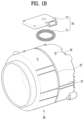
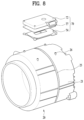
- the induction module 70 includes a coil 71 which receives electric current and generates a magnetic field so that eddy current is generated at the drum, and a module cover 72 for accommodating the coil 71 therein.
- the coil comprises a wire through which an electric current is configured to pass so as to generate a magnetic field.
- the module cover 72 may be formed in the shape of a box that has one open surface. Specifically, the module cover 72 may have a box shape in which the surface thereof facing the drum is open and the opposite surface thereof is closed. Therefore, the coil 71 is located inside the module cover 72, or the module cover 72 covers the upper portion of the coil 71. The module cover 72 functions to protect the coil 71 from the outside. Further, as will be described later, the module cover 72 functions to cool the coil 71 by forming an air flow path between the module cover 72 and the coil 71.
- the eddy current is dissipated by the resistance of the drum 30, which is a conductor, and is converted into heat.
- the drum 30 is heated by the heat generated by the resistance, and the temperature in the drum 30 rises as the drum 30 is heated.
- the tub 20 has a cylindrical shape because the drum 30 rotates to wash or dry clothes (hereinafter, referred to as 'laundry').
- the coil 71 may be provided so as to be wound around the entire outer circumferential surface of the tub 20 at least once.
- the coil 71 is wound around the entire circumference of the tub 20, it requires too much wire. In addition, a short circuit or other problems may occur due to contact between the coil and the wash water leaking from the tub 20.
- an induced magnetic field may be generated in the opening 22 in the tub 20 and the driving unit 40, and thus may fail to directly heat the outer circumferential surface of the drum 30.
- the coil 71 it is desirable for the coil 71 to be provided only on a portion of the outer circumferential surface of the tub 20. That is, the coil 71 may be provided so as to be wound around a certain region from the front side of the tub 20 to the rear side thereof at least once, rather than being wound around the entire outer circumferential surface of the tub 20.
- the coil 71 may be formed to have a single-layer structure. That is, the wire may be wound in a single layer, rather than in multiple layers. In the case in which the wire is wound in multiple layers, a gap is inevitably formed between adjacent portions of the wire. That is, a gap is inevitably formed between a portion of the wire that is located in the bottom layer and a portion of the wire that is located in the top layer. Therefore, the distance between the portion of the coil that is located in the top layer and the drum is increased. In one example, even if such a gap can be physically eliminated, the greater the number of layers of the coil, the longer the distance between the portion of the coil that is located in the top layer and the drum, which leads to deterioration in efficiency.
- the induction module is illustrated as being provided on the upper portion of the tub 20.
- the induction module may be provided on at least one of the upper portion, the lower portion, and both side portions of the tub.
- the driving unit 40 operates to rotate the drum 30.
- the drum 30 may be rotated at any speed by the driving unit 40.
- the entire surface of the drum 30 can be heated, and the laundry in the drum 30 can be evenly exposed to heat.
- the induction module is not mounted on a plurality of portions (e.g. the upper portion, the lower portion, both side portions, etc.) of the outer circumferential surface of the tub 20 but is mounted only on one portion, the outer circumferential surface of the drum 30 can be evenly heated.
- the sterilizing-washing process in which laundry is washed while being immersed in the heated wash water, can be realized by a method using a much smaller amount of wash water. In other words, since it is not necessary to heat wash water, which has a high specific heat, energy can be saved.
- the laundry treatment apparatus is capable of eliminating a heater provided on the lower side of the tub to heat wash water, thus simplifying construction and increasing the volume of the tub.
- the induction module 70 is disposed on an upper face of the drum 30 in the outer circumferential face of the tub 20.
- At least two induction modules may be disposed along a front-rear direction of the tub 20. That is, arranging a plurality of induction modules on the outer circumferential face of the tub 20 in a front-rear directional manner may allow the outer circumferential face of the drum 30 to be uniformly heated.
- the energy efficiency may be increased by selectively driving the front induction module and the rear induction module depending on the position of the laundry.
- the laundry when the amount of the laundry M is small, the laundry may be biased behind the drum. This is because a tilting drum is often used. Conversely, when there is a large amount of laundry, the laundry may be evenly distributed in a front-rear direction of the drum.
- the induction module When the induction module is provided in a range from the foremost part to the rearmost part of the drum 30 and is provided at or about a vertical portion of the drum, a door, a circulation duct, a spray nozzle, and the like provided between the drum 30 and the tub 20 may be heated.
- the induction module When the induction module is provided in a range from the rearmost part of the drum 30 to the vertical portion of the drum, the drive unit 40 for the drum 30 may be heated. This situation should be avoided.
- FIG. 3 shows examples of a top view of the coil. That is, FIG. 3 shows the coil as viewed from above.
- the coil 71 may be wound at least once while maintaining the circular shape. That is, it is assumed that B be a length of the coil in the front-rear direction of the tub 20, and a length of the coil in the width direction or the left-right directional direction of the tub 20 is defined as A. The lengths A and B may be the same.
- the coil 71 may be arranged to form a flat structure.
- the coil 71 may be formed in a shape having a curved portion at each of left and right portions with considering the cylindrical outer circumferential face of the tub 20. In the latter case, the spacing between the coil 71 and drum 30 may be reduced along the outer face of the drum 30.
- the coil 71 may be wound at least once. Upper and lower coils may be spaced apart from each other. That is, a plurality of coils may be arranged in the front-rear direction of the tub 20.
- the shape of coil 71 and the number of coils 71 may vary. In one example, the shape of coil 71 and the number of coils 71 may vary, depending on the capacity of the laundry treatment apparatus, that is, depending on the outer diameter or front-rear directional length of the tub or drum.
- a 100 percent efficiency is assumed when the same coil is located at the position corresponding to the center of the drum.
- a forwardly position-biased coil has an efficiency of about 96 percent while a rewards position-biased coil has an efficiency of about 90 percent.
- a configuration in which the coil is installed in a shape extending in the front-rear direction around the center of the drum it may be seen that a configuration in which the center of the coil position-corresponds to the center of the drum is the most effective.
- the areas of the coils position-corresponding to the center of the drum are inevitably reduced.
- adjacent parts of the two coils may position-correspond to the center of the drum. Therefore, on the assumption that one coil in the former case has the same coil area as a total coil area of the two coils in the latter case, it may be seen that the coil arrangement shown in FIG. 3A is more efficient in terms of heating performance than the coil arrangement shown in FIG. 3C .
- the coil is formed such that a proportion of the coil is concentrated on the central portion of the coil. That is, I may be the most efficient that the central portion of the coil defines a single vertical line.
- the coil has a single center axis.
- the coil of FIG. 3B has a center axis as a single vertical face.
- the central axis in FIG. 3C may be defined as two vertical lines or two vertical faces.
- the coils in FIG. 3B and FIG. 3C exhibit the average temperature of the drum lower than that for the coil FIG. 3A .
- These results show that the performance of the single coil is better than a total performance of a plurality of coils. It may also be seen that the closer the center axis of the coil looks like to a single vertical line than to a single vertical face, the better the performance thereof.
- the coil in FIG. 3B may be more desirable than the coil in FIG. 3A .
- the coil in FIG. 3A may be more desirable than the coil in FIG. 3A .
- the laundries may be evenly heated in the front-rear direction of the drum and the entire laundry may be heated evenly, although the heating efficiency is reduced by some extent.
- the heating efficiency and drying efficiency may vary depending on the shape of the coil.
- the heating efficiency may be referred to as an output energy (heated amount of the drum) relative to an input energy.
- the heating efficiency may refer to a ratio at which the electrical energy applied to the induction module is converted to the thermal energy that heats the drum.
- the drying efficiency may be referred to as the input versus output until the entire laundry has been fully dried. In the latter case, a time factor may be further considered.
- the coil in FIG. 3B is more preferable than the coil in FIG. 3A . That is, in FIG. 3A , the center axis of the coil looks like close to a single vertical line, so that the heating efficiency is relatively high but the drying efficiency is relatively small.
- the coil is preferably positioned to face the front-rear directional center of the drum.
- the change of the position of the coil and the change of the heating efficiency are independent of each other.
- the position of the coil may be considered.
- the coil 71 is a single coil and is formed in an elliptical shape or a track shape having a long axis in the front-rear direction of the drum. Further, a center of the coil 71 preferably faces the front-rear directional center of the drum.
- the module cover 72 may be provided to cover the coil 71.
- the module cover 72 is provided in the shape of a box whose bottom face is opened to prevent the coil 71 from being detached from the tub 20 due to external vibration.
- the module cover 72 may has a lateral space defined therein through which the coil 71 is received in the cover 72.
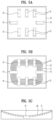
- FIG. 4A shows the module cover 72 as viewed from the bottom.
- the module cover 72 may have a plurality of coil fixing portions 73 radially arranged to be spaced apart from each other so that while a form of the coil 71 is smoothly maintained, the coil 71 is wound.
- the coil fixing portions 73 may be integrally formed with the module cover 72.
- the module cover 72 may be formed via a plastic injection.
- Each of the coil fixing portions 73 may include a bar shaped support 731.
- the support 731 may be provided to press the coil 71 downwardly. Therefore, since the coil 71 is pushed downwardly by the support 731, the overall shape of the coil 71 may be held without being deformed.
- Each of the coil fixing portions 73 may include a protrusion 732 protruding downward from each of both ends of the support 731.
- Outer protrusions 732 and inner protrusions 732 may be defined to surround the coil 71 radially outwardly and radially inwardly of the coil 71 respectively. Therefore, the coil 71 may be prevented from being pushed radially inwards or outwards to be deformed.
- FIG. 4B shows an internal view of the module cover 72 as viewed from a top.
- the coil 71 begins to wind along the radially inner protrusions 732 of the coil fixing portions 73 and reaches the radially outer protrusions 732 of the coil fixing portions. Thus, the winding of the coil 71 may be completed.
- the coil 71 may be secured in the module cover 72 while maintaining its shape.
- the coil fixing portions 73 may act as a mold for forming the coil while performing a function for fixing the coil. That is, a contour and size of the coil are determined in accordance with the coil fixing portions 73. Accordingly, the coil may be conformed to the coil fixing portions 73. In other words, the coil 71 may be formed using the coil fixing portions 73. Moreover, the coil fixing portions 73 may allow the coil to be be kept from being distorted or deformed.
- the support 731 of the coil fixing portions 73 may be configured to seat the coil thereon and the protrusion 732 may be configured to prevent the coil from moving.
- These coil fixing portions may be formed along the longitudinal direction of the coil. Therefore, the entire coil can be stably formed and its shape can be maintained by the coil fixing portions 73.
- drum 30 is cylindrical and thus a cross-section of the outer circumferential face of the drum 30 perpendicular to the ground has a rectangular cross-sectional shape.
- winding the coil 71 in a perfectly rectangular shape may be difficult realistically with considering a material of the coil 71 and a coil winding process. Therefore, it may be more desirable to wind the coil 71 into the track shape as close to a rectangular shape as possible.
- the track shape may allow the coil area to be further increased as compared with the elliptical shape.
- an area by which the inside of the rectangle is filled is larger in the track shaped coil than in the elliptical shaped coil. This is because, for the track shaped coil, the area occupied by the coil at four corner portions may be further increased compared to the elliptical shaped coil.
- a portion of the coil 71 wound on each of the front and the rear portions of the tub 20 is curved.
- Each of both side portions of the coil 71 connecting the front and the rear portions of the tub 20 may has a straight line shape. Only each edge portion of the coil 71 may be formed in a round shape.
- FIG. 5 shows an embodiment in which the coil 71 may be wound in the form of a track.
- the coil fixing portions 73 are not arranged in a radial shape, but are arranged in a row at each of upper and lower portions with reference to the drawing.
- Each of coil fixing portions 73 provided on middle sides may be oriented to perpendicular to an orientation of each of the upper and lower coil fixing portions 73 arranged in a line.
- a left side of FIG. 5A as the forward direction of the tub 20 and a right side of FIG. 5A as the rear direction of the tub 20
- a plurality of coil fixing portions 73 provided on each of both lateral portions of the tub 20 are provided in a row, while each of the coil fixing portions 73 provided on the front and rear of the tub 20 may be oriented perpendicularly to an orientation of each of the coil fixing portions 73 on the both lateral portions of the tub 20.
- the coil 71 extends linearly along the coil fixing portions 73 provided along both lateral portions of the tub 20.
- the coil 71 has a curvature to wind around the coil fixing portions 73 provided along the front and rear portions of the tub 20.
- the coil 71 may be wound into a track shape when the coil 71 is wound along the arrangement of the coil fixing portions 73.
- the coil 71 may generate an eddy current in a wider area of the outer circumferential face of the drum 30.
- the coil fixing portion provided on the outer circumferential face of the tub and having an orientation perpendicular to the rotation axis of the drum is referred to as a first coil fixing portion
- the coil fixing portion provided on the outer circumferential face of the tub and having an orientation parallel to the rotation axis of the drum is referred to as a second coil fixing portion.
- an orientation of each of the first and second coil fixing portions 73 is perpendicular to the winding direction of the coil or the longitudinal direction of the coil (more specifically, the longitudinal direction of the wire).
- FIG. 4 and FIG. 5 show that the coil 71 is wound into a planar form parallel to the ground.
- the present disclosure is not limited thereto.
- One face of the module cover 72 where the coil fixing portions 73 are provided may have a curvature according to the radius of curvature of the drum 30 or the radius of curvature of the tub 20.
- the coil 71 may be provided to correspond to the radius of curvature of the drum 30 because the coil 71 is wound according to the curvature of the module cover 72.
- the radius of curvature of the tub is larger than the radius of curvature of the drum.
- the coil 71 has the radius of curvature equal to the radius of curvature of the drum 30, the spacing between the coil and the drum may be minimized along the entire region of the coil.
- the coil 71 since the coil 71 is located on the outer circumferential face of the tub, it is preferable that the coil 71 conforms to the outer circumferential face of the tub.
- the coil 71 may be formed into the curved shape having the same radius of curvature as the radius of curvature of the outer circumferential face of the tub.
- FIG. 5C shows one example where the coil 71 is formed into the curved shape having the same radius of curvature as the radius of curvature of the outer circumferential face of the tub 20.
- the spacing between the coil 71 and the drum 30 may remain constant as it goes outwardly from the center of the coil 71. This may generate an eddy current of the uniform intensity on the outer circumferential face of the drum 30. That is, the outer circumferential face of the drum 30 may be evenly heated.
- the coil when the coil is formed by winding a wire around the coil fixing portions 73, there may be a possibility of short-circuiting between adjacent wires in close contact with each other.
- the wire 71 may be coated with a coating film such as an insulating film separately.
- a coating film such as an insulating film separately.
- the coil 71 is overheated by its own resistance. The cooling of the coil 71 may be difficult such that the insulating film may still have the risk of melting.
- an additional cost may be incurred when the insulating coating is applied to form a thick insulating film on the wire forming the coil 71.
- the coils are arranged to be spaced apart from each other when the coils 71 are wound around the induction module. This may reduce the thickness of the insulation coating.
- the coils 71 are wound at least once along a direction from a front to a rear of the tube 20 on the induction module, the coils are wound to have a predetermined spacing between the coils so as not to contact each other.
- the coils 71 does not contact each other and there is no possibility of the short circuit therebetween.
- the heat of the coil 71 can also be easily cooled.
- the area of the wound coil 71 itself may be wider, thereby heating a larger area of the outer circumferential face of the drum 30.
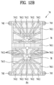
- FIG. 6 shows the base housing 74 by which the coil is shaped and to which the coil is fixed.
- the base housing 74 may be integrally formed with the tub 20 via a plastic injection.
- a wire may be inserted into the base housing 74 to form the coil 71.
- the spacing between adjacent wires may be maintained, and the wire may be fixed. Therefore, the entire coil may be fixed without being deformed.
- the induction module 70 may further include the base housing 74 that allows the wires to be spaced apart from one another when the wires of the coil 71 are wound at least one time forwardly and backwardly of the tub 20 on the induction module.
- the base housing 74 may also be coupled to the module cover 72. Accordingly, the base housing and the module cover may be coupled to each other to form an internal space receiving the coil therein. Therefore, the base housing and the module cover may be referred to as a module housing.
- the base housing 74 may be coupled to the module cover 72 to be received in the module cover 72.
- the fixing rib 7421 may define the top face of the base 741.
- the receiving portion 7422 may be depressed downwards to allow the fixing rib 7421 to upwardly protrude relative to the receiving portion.
- the protruding ribs 7423 may serve as a measure of a relative position of the fixing rib 7421. In other words, it may be determined based on the protruding rib 7423 that the fixing rib 7421 is located inside or outside the protruding rib 7423. This may allow for easy identification of the number of turns or area of the coil 71 when the coil 71 is wound around the fixing rib 7421.
- the module cover 72 is formed in the shape of a box that has one open surface, in the case in which the module cover 72 accommodates the coil 71 or the base 74 therein, it can focus the magnetic field in the direction toward the drum 30.
- the additional blocking member 77 may be omitted.
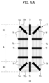
- the permanent magnet 75 may be configured as a bar magnet, and may be located on the coil 71 while being arranged perpendicular to the longitudinal direction of the coil 71. This is for covering both an inner coil portion located at a radially inward position and an outer coil portion located at a radially outward position at the same time.
- the coil 71 may be sectioned into both end portions B1 and B2, which include a front end portion B1 located adjacent to the front side of the tub 20 and a rear end portion B2 located adjacent to the rear side of the tub 20, and an intermediate portion A, which is located between the front end portion B1 and the rear end portion B2 and has a larger area than the front end portion B1 and the rear end portion B2.
- the permanent magnets 75 may be arranged such that the number thereof disposed on the front end portion B1 or the rear end portion B2 of the coil is equal to or greater than that disposed on the intermediate portion A of the coil.
- the embodiment shown in FIG. 9B can further improve efficiency by more evenly heating the drum than the embodiment shown in FIG. 9A .
- the magnetic flux density in the both end portions B1 and B2 of the coil is increased through the dense arrangement of the permanent magnets, with the result that the drum 30 is evenly heated in the longitudinal direction thereof.
- the embodiment shown in FIG. 9B may be more efficient than the embodiment shown in FIG. 9A .
- the number of permanent magnets used for each portion of the coil is the same, it may be desirable to move the permanent magnets located in the intermediate portion A of the coil to positions adjacent to the both end portions B1 and B2 of the coil in terms of efficiency. Therefore, in the case in which the total magnetic flux density is determined through the permanent magnets, it is desirable that the magnetic flux density in the both end portions of the coil be set to be larger than the magnetic flux density in the intermediate portion of the coil.
- the above-described embodiment related to the winding form of the coil 71 and the above-described embodiment related to the arrangement of the permanent magnets 75 can be applied to a single laundry treatment apparatus without any contradiction. That is, it is possible to obtain the effect of more evenly heating the drum 30 when the above-described embodiment related to the winding form of the coil and the above-described embodiment related to the arrangement of the permanent magnets are combined, compared with when these embodiments are implemented individually.
- the coil 71 may be formed in any shape, such as a concentric circle, an ellipse, a track, etc., as long as the coil 71 can be formed on the outer circumferential surface of the tub 20 by winding the wire 76.
- the extent to which the drum 30 is heated may vary depending on the wire-winding shape. This has been described above.
- the amount of the magnetic field transferred to the center of the drum 30 and the amount of the magnetic field transferred to the front and rear sides of the drum 30 may be significantly different from each other.
- the amount of the magnetic field that is transferred to the front side of the circumferential surface of the drum 30 is relatively small.
- the area of the coil that is located near the center of the drum 30 is relatively large, the amount of the magnetic field that is transferred to the center of the circumferential surface of the drum 30 is relatively large. Therefore, it is difficult to evenly heat the drum 30.
- the coil it is desirable for the coil to be formed in a rectangular shape, rather than a square shape. That is, it is desirable that the width in the forward-and-backward direction of the coil be greater than the width in the lateral direction thereof. Accordingly, it is possible to expand the center portion of the coil, which has a relatively large area, in the direction from the center of the drum to the front and rear ends of the drum.
- the wire 76 may be wound such that the coil 71 includes straight portions 71a and 71b and a curved portion 71c.
- the inner coil portion and the outer coil portion may have the same radius of curvature as each other. That is, it is desirable that the radius of curvature of the wire at a position close to the center of the coil and the radius of curvature of the wire at a position distant from the center of the coil be the same.
- the radius of curvature in the straight portions 71a and 71b is meaningless, and thus the same radius of curvature is meaningful in the curved portion 71c. In the case of FIG.
- the radius of curvature in the curved portion 71c is different for each portion of the coil located in the radial direction. Specifically, in the case of FIG. 10B , the radius of curvature in the curved portion 71c is gradually increased in the radially outward direction.
- the straight portions 71a and 71b include a front straight portion 71b located on the front side of the outer circumferential surface of the tub 20 and a rear straight portion 71b located on the rear side of the outer circumferential surface of the tub 20, which are collectively referred to as horizontal (lateral) straight portions, and further includes a vertical (longitudinal) straight portion 71a, which is formed perpendicular to the horizontal straight portions 71b. It is desirable that the length of the vertical straight portion be greater than the length of the horizontal straight portion. That is, in the case in which the coil is formed in an elliptical shape or a track shape, it is desirable that the long axis of the coil be formed in the forward-and-backward direction of the tub.
- the curved portion 71c is formed at the position at which the horizontal straight portion 71b and the vertical straight portion 71a meet. That is, the coil may be formed by four curved portions 71c, which have the same radius of curvature as each other, and four straight portions.
- the both end portions B1 and B2 of the coil which include the front end portion located adjacent to the front side of the tub 20 and the rear end portion located adjacent to the rear side of the tub 20, and the intermediate portion A of the coil, which is located between the front end portion B1 and the rear end portion B2, may have uniform lateral widths.
- the curved portion may be formed such that the inner coil portion and the outer coil portion have the same radius of curvature as each other, with the result that the curved portion may be formed so as to maximally approximate to the shape of the corner of a rectangle.
- a first radius of curvature of an inner coil portion of the curved portion of the coil being the same as a second radius of curvature of an outer coil portion of the curved portion of the coil.
- the amount of the magnetic field radiated from the both end portions B1 and B2 of the coil to the front and rear portions of the circumferential surface of the drum 30 can be set as close as possible to the amount of the magnetic field radiated from the intermediate portion A of the coil to the center of the circumferential surface of the drum 30. That is, the amount of the magnetic field, which may be reduced at the both end portions of the coil due to the shape thereof, can be compensated for as much as possible through the uniform radius of curvature in the curved portion.
- This uniform heating which can be achieved through the above-described shape of the coil and the uniform radius of curvature in the curved portion, may be more effectively performed through magnetic field concentration using the above-described ferrite. That is, the magnetic field may be further focused on the front and rear sides of the drum than on the center of the drum by the ferrite. In other words, the magnetic field that is excessively focused on the center of the drum may be dispersed to the front and rear sides of the drum. This dispersion method is very economical and effective. In the case in which the amount of the magnetic field that can be focused by the ferrite is determined, the arrangement of the ferrite may be appropriately concentrated on the regions corresponding to the front and rear ends of the drum.
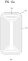
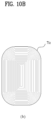
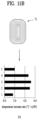
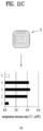
- FIG. 11 show coils 71 having different vertical lengths from each other and the temperature rise distribution of the circumferential surface of the drum 30 depending on the longitudinal widths of the coils 71.
- the vertical axis represents portions of the outer circumferential surface of the drum 30.
- '1' denotes the rear portion of the outer circumferential surface of the drum 30
- '5' denotes the front portion of the outer circumferential surface of the drum 30
- '2' to '4' denote the portions between the rear portion of the outer circumferential surface of the drum 30 and the front portion thereof.
- the horizontal axis represents the temperature rise rate of the drum 30.
- FIG. 11A shows the case in which the drum is heated using the coil having the largest longitudinal width
- FIG. 11B shows the case in which the drum is heated using the coil having a medium longitudinal width
- FIG. 11C shows the case in which the drum is heated using the coil having the smallest longitudinal width.
- the temperature rise rate is substantially uniform over the front and rear portions and the center of the drum 30.
- the temperature rise rate is significantly different between the front and rear portions of the drum 30 and the center of the drum 30.
- the temperature rise rate is somewhat different between the front and rear portions of the drum 30 and the center of the drum 30.
- the front and rear portions and the center of the drum 30 can be more evenly heated as the longitudinal width of the coil 71 becomes longer. This can be realized by expanding a large portion of the coil from the region corresponding to the center of the drum to the regions corresponding to the front and rear portions of the drum.
- the efficiency with which electric energy is converted into thermal energy increases as the shape of the coil more closely approximates a circle or a square.
- the reason for this is that the closer the center of the magnetic field is to a single axis (line), the smaller the amount of magnetic field that leaks.
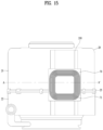
- the module-mounted portion 210 includes the straight region 211, and the distance between the straight region 211 and the center of the tub may be set to be less than the radius of the tub. In one example, the distance between the straight region and the center of the tub may vary within a range smaller than the interval between the outer circumferential surface of the tub 20 having the reference radius and the drum 30.
- the straight region may be said as a flat region.
- the module-mounted portion 210 may include a rectangular-shaped surface, and the straight region 211 may form a width in the circumferential direction of the rectangular-shaped surface.
- the shape of the module-mounted portion 210 is not limited to a rectangular shape.
- the shape of the module-mounted portion 210 may include a circular shape, a diamond shape, an oblique rectangular shape, and the like.
- the rectangular-shaped surface may be formed such that the width in the axial direction thereof is greater than the width in the circumferential direction thereof.
- the width in the circumferential direction of the rectangular-shaped surface is inevitably limited in consideration of the distance from the drum 30. Therefore, it is desirable to increase the area on which the induction module 70 can be mounted by increasing the width in the axial direction.
- the straight region of the module-mounted portion 210 may include connection regions 212 for connecting both ends of the straight region to the circumferential surface of the tub 20.
- the connection regions 212 may be formed in a curved or straight shape.
- the connection regions 212 may also be formed further radially inwards than the outer circumferential surface of the tub 20 having the reference radius in order to reduce the distance from the outer circumferential surface of the drum 30.
- the length of the straight region 211 may be limited in consideration of the distance from the drum 30, and the width in the circumferential direction of the induction module 70 may exceed the straight region 211.
- the induction module 70 may be located at the center of the straight region 211. Specifically, the center portion of the coil 71 of the induction module 70 may be located in a virtual plane, which includes the rotational axis of the drum 30 and is perpendicular to the straight region 211.
- the coil 71 of the induction module 70 is provided on the module-mounted portion 210 such that the center portion thereof is the closest to the drum 30 and such that the distance from the drum 30 is gradually increased from the center portion to both ends thereof.
- the distance from the center of the straight region 211 to the drum 30 is minimized, and the distance from the drums 30 is gradually increased from the center of the straight region 211 to both sides thereof.
- the magnetic field generated by the coil 71 wound in the circumferential direction of the tub 20 generates a strong induced current in the drum 30.
- the distance between the coil and the outer circumferential surface of the drum may vary in the range from about 24 to 30 mm.
- the distance between the coil and the outer circumferential surface of the drum at the center of the straight region may be about 24 mm, and the distance at both ends of the straight region may be about 28 mm. Therefore, the distance from the outer circumferential surface of the drum is substantially reduced in a large portion of the entire area of the coil.
- the straight region 211 in the above embodiment may be formed at the center of the module-mounted portion 210. Therefore, it is possible to further concentrate the coil at the portion corresponding to the straight region 211.
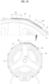
- module-mounted portion 210 on which the induction module 70 is mounted, will be described with reference to FIGs. 17 and 18 .
- structure of mounting the induction module 70 to the module-mounted portion 210 will be described.
- the module-mounted portion 210 may include a first straight region 211a and a second straight region 211b in the cross-section thereof that is perpendicular to the rotational axis of the drum 30.
- the first straight region and the second straight region may be located at positions further radially inward than the reference radius of the tub.
- the first straight region and the second straight region may be considered zero gradients.
- first straight region 211a and the second straight region 211b may be connected to each other via a connection region 212.
- the connection region 212 may be formed in a curved or straight shape.
- Each of the first straight region 211a and the second straight region 211b may form a width in the circumferential direction of a rectangular-shaped surface included in the module-mounted portion 210.
- the rectangular-shaped surface is formed to facilitate the formation and the installation of the induction module 70, and is not limited to the rectangular shape.
- the module-mounted portion 210 may be formed such that at least two rectangular-shaped surfaces are connected to each other. In other words, two straight regions located at both sides may be connected to each other via a curved region located at a center portion.
- the module-mounted portion 210 may be formed by combining the straight regions and the curved region.
- the straight region 211 cannot be formed over a predetermined length in consideration of the interval between the drum 30 and the tub 20. Therefore, the module-mounted portion 210, which includes the first straight region 211a and the second straight region 211b, can form a large area in the circumferential direction without being in contact with the drum 30.
- both ends of the straight region 211 or one end of the straight region 211 may be provided outside the reference radius of the tub.
- the region provided outside the reference radius of the tub may be considered a region extending in the radial direction of the tub.
- this extending region may be only a portion for mounting the induction module on the base housing 74. That is, the coil may not be located in the extending region. This is because the coil 71 is located inside the base housing 74 so that the edges of the base housing 74 surround the coil 71. In other words, a spacing interval is provided between the coil 71 and the outermost edge of the base housing 74, and the spacing interval may be opposite the extending region.
- the length of the first straight region 211a and the length of the second straight region 211b may be equal to each other.
- the length of the straight region 211 means the distance from the drum 30. When the length is short, the distance from the drum 30 is long. Thus, it is desirable that the first straight region and the second straight region be formed symmetrical to each other. Through this configuration, it is possible to easily form the induction module and to securely fix the induction module to the module-mounted portion.
- the induction module 70 may be provided over the first straight region 211a and the second straight region 211b of the module-mounted portion 210. Specifically, both ends in the circumferential direction of the induction module 70 are located at the centers of the first straight region 211a and the second straight region 211b, and the center of the induction module 70 is located in the region to which the first straight region 211a and the second straight region 211b are connected.
- the coil 71 of the induction module 70 may be formed so as to be wound at least once between the front side of the tub 20 and the rear side thereof around the connection region 212.
- the induction module in the case in which the coil 71 is wound parallel to the module-mounted portion 71, the induction module may be located closest to the drum 30 at both ends in the circumferential direction of the tub, and the distance from the drum 30 may be gradually increased from the both ends in the circumferential direction of the tub to the center portion thereof.
- the magnetic field generated by the coil 71 wound in the axial direction of the tub 20 generates a strong induced current in the drum 30.
- the distance between the coil and the drum is constant, e.g. about 30 mm, in the circumferential direction.
- the connection region 212 shown in FIG. 18 is a curved region that has the same curved shape as the tub. Therefore, the distance between the coil and the outer circumferential surface of the drum in the curved region is constant, e.g. about 30 mm.
- the distance between the coil and the outer circumferential surface of the drum may vary in the range from about 24 to 30 mm.
- the distance between the coil and the outer circumferential surface of the drum at the center of the straight region may be about 24 mm, and the distance at both ends of the straight region may be about 26 mm. Therefore, the distance from the outer circumferential surface of the drum is substantially reduced in a large portion of the entire area of the coil.
- efficiency can be increased by reducing the distance between the coil and the outer circumferential surface of the drum by forming the module-mounted portion 210 to have a straight region in the circumferential direction of the tub.
- the straight region may be matched with the shape of the base housing forming the coil.
- the module-mounted portion and the tub may be more securely coupled to each other through the combination of the straight region and the curved region.
- the coil it has been described that it is desirable for the coil to have a hollow center portion.
- the center portion of the coil is hollow in a track shape.
- Such a hollow portion may correspond to the curved region, i.e. the connection region 212, in FIG 18 . Therefore, the portion where the coil is formed may substantially correspond to the straight region. Therefore, it is more desirable to form straight regions at the left and right portions of the module-mounted portion 210 and to form a curved region between the straight regions, i.e. at the lateral center of the module-mounted portion.
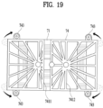
- the structure of the induction module 70 particularly the structure and position of the coupling portions 743 of the base housing 74 will be described in detail with reference to FIG. 19 .
- the induction module 70 may be formed long in the axial direction of the drum 30.
- the length of the straight region 211 of the module-mounted portion 210, on which the induction module 70 is mounted, is limited, and thus it is desirable for the induction module to evenly heat the drum 30 with a minimum area in consideration of the rotating direction of the drum 30.
- the length in the axial direction of the coil 71 may be shorter than the length of the drum 30, which can be heated, by about 20 to 40 mm.
- the coil 71 may be formed so as to be spaced apart from the front and rear sides of the drum, which can be heated, by about 10 to 20 mm.
- the base housing 74 may be coupled to the outer circumferential surface of the tub 20 or the module-mounted portion 210 through the coupling portions 743, which protrude from both ends in the circumferential direction thereof and extend in the circumferential direction.
- the coupling portions 743 may be provided at both ends in the circumferential direction of the front and rear sides of the base housing 74.
- this embodiment proposes an example in which the coupling portions 743 protrude from both lateral sides of the base housing in the circumferential direction. That is, according to this example, the length of the base housing 74 surrounding the outer circumferential surface of the tub is further increased by the coupling portions 743. As described above, the base housing 74 and the module-mounted portion 210 may be formed through the combination of the straight region and the curved region on the outer circumferential surface of the tub in the circumferential direction. Therefore, the base housing 74 may be more securely coupled and fixed to the tub merely by extending the coupling portions 743 without extending the base of the base housing 74 in the circumferential direction. In other words, it is possible to more securely couple and fix the base housing by forming the coupling portions at the front end and the rear end of both sides of the base housing, rather than forming the coupling portions at both ends of the front and rear portions of the housing.
- the base housing 74 may be formed as long as possible in the axial direction while securing a space in the base housing 74 for accommodating the coil 71 therein.
- the distance between the base housing 74 and the drum 30 may be minimized by bringing the base housing 74 into close contact with the cylindrical-shaped tub 20.
- a condensing port 230 may be provided in or near the third quadrant 3S of the tub 20 to cool the heated wet air so as to condense water. That is, the condensing port 230 may be provided to supply the cooling water from the outside of the tub to the inside of the tub so as to cool the heated wet air inside the tub.
- the inside of the tub corresponding to the third quadrant 3S, to which the cooling water is supplied, is influenced by low-temperature condensate water.
Landscapes
- Engineering & Computer Science (AREA)
- Textile Engineering (AREA)
- Control Of Washing Machine And Dryer (AREA)
- Detail Structures Of Washing Machines And Dryers (AREA)
- Main Body Construction Of Washing Machines And Laundry Dryers (AREA)
Claims (16)
- Wäschebehandlungsvorrichtung, die aufweist:einen Bottich (20) mit einem Modulbefestigungsabschnitt (210), der an einer Außenumfangsfläche des Bottichs (20) angeordnet ist;eine Trommel (30), die drehbar innerhalb des Bottichs (20) angeordnet und so konfiguriert ist, dass sie Wäsche darin aufnimmt, wobei die Trommel (30) aus einem Metallmaterial besteht; undein Induktionsmodul (70), das an dem Modulbefestigungsabschnitt (210) des Bottichs (20) angeordnet und so konfiguriert ist, dass es ein elektromagnetisches Feld erzeugt, um die Trommel (30) zu erwärmen,dadurch gekennzeichnet, dassder Modulbefestigungsabschnitt (210) einen flachen Abschnitt (211) aufweist, der weiter radial innen als eine Außenumfangsfläche des Bottichs (20) angeordnet ist.
- Wäschebehandlungsvorrichtung nach Anspruch 1, wobei der
Modulbefestigungsabschnitt (210) an einem oberen Abschnitt der Außenumfangsfläche des Bottichs (20) angeordnet ist, wobei der Modulbefestigungsabschnitt (210) ferner einen Verbindungsbereich (212) aufweist, der sich von mindestens einem Ende des flachen Abschnitts (211) in einer Umfangsrichtung des Bottichs (20) erstreckt und der mit der Außenumfangsfläche des Bottichs (20) verbunden ist. - Wäschebehandlungsvorrichtung nach Anspruch 2, wobei der flache Abschnitt (211) einen ersten geraden Bereich (211a) und einen zweiten geraden Bereich (211b) aufweist, die durch den Verbindungsbereich (212) miteinander verbunden sind.
- Wäschebehandlungsvorrichtung nach einem der Ansprüche 1 bis 3, wobei das Induktionsmodul (70) aufweist:ein Basisgehäuse (74), das an dem Bottich (20) angeordnet ist; undeine Spule (71), die an dem Basisgehäuse angeordnet und so konfiguriert ist, dass sie ein Magnetfeld erzeugt, wenn ein elektrischer Strom an die Spule (71) angelegt wird.
- Wäschebehandlungsvorrichtung nach einem der Ansprüche 1 bis 4, wobei der flache Abschnitt (211) eine Oberfläche aufweist, die relativ zu einer Umfangslinie der Außenumfangsfläche des Bottichs (20) radial nach innen eingedrückt ist.
- Wäschebehandlungsvorrichtung nach einem der Ansprüche 1 bis 5, wobei ein Abstand zwischen der Trommel (30) und dem Modulbefestigungsabschnitt (210) des Bottichs (20) geringer ist als ein Abstand zwischen der Trommel (30) und einem Abschnitt der Außenumfangsfläche, der benachbart zu dem Modulbefestigungsabschnitt (210) positioniert ist.
- Wäschebehandlungsvorrichtung nach einem der Ansprüche 1 bis 6, wobei eine Innenumfangsfläche des Bottichs (20) (i) einen ersten Abschnitt, der dem Modulbefestigungsabschnitt (210) entspricht, und (ii) einen zweiten Abschnitt aufweist, der in einer Umfangsrichtung des Bottichs (20) benachbart zu dem ersten Abschnitt angeordnet ist, und
wobei der erste Abschnitt der Innenumfangsfläche relativ zu dem zweiten Abschnitt der Innenumfangsfläche des Bottichs (20) radial innen angeordnet ist. - Wäschebehandlungsvorrichtung nach einem der Ansprüche 1 bis 7, wobei sich der flache Abschnitt (211) von einem vorderen Abschnitt des Bottichs (20) zu einem hinteren Abschnitt des Bottichs (20) erstreckt.
- Wäschebehandlungsvorrichtung nach Anspruch 8, wobei der flache Abschnitt (211) an einem mittleren Abschnitt des Bottichs (20) zwischen dem vorderen Abschnitt des Bottichs (20) und dem hinteren Abschnitt des Bottichs (20) angeordnet ist, und wobei eine Länge des Modulbefestigungsabschnitts (210) in einer Vorne-Hinten-Richtung des Bottichs (20) geringer ist als eine Länge des Bottichs (20) in der Vorne-Hinten-Richtung des Bottichs (20).
- Wäschebehandlungsvorrichtung nach einem der Ansprüche 2 bis 9, wobei der Verbindungsbereich (212) eine gekrümmte Form oder eine gerade Form hat.
- Wäschebehandlungsvorrichtung nach einem der Ansprüche 1 bis 10, wobei eine Breite des Induktionsmoduls (70) in der Umfangsrichtung des Bottichs (20) größer ist als eine Breite des flachen Abschnitts (211) in der Umfangsrichtung des Bottichs (20).
- Wäschebehandlungsvorrichtung nach einem der Ansprüche 1 bis 10, wobei der Verbindungsbereich (212) mehrere Verbindungsbereiche aufweist, die mit Enden des flachen Abschnitts (211) verbunden sind, und
wobei der Modulbefestigungsabschnitt (210) den flachen Abschnitt (211) und die mehreren Verbindungsbereiche (212) aufweist. - Wäschebehandlungsvorrichtung nach einem der Ansprüche 2 bis 12, wobei das Induktionsmodul (70) eine Spule (71) aus Drähten (76) aufweist und zwischen einer vorderen Seite des Bottichs (20) und einer hinteren Seite des Bottichs (20) angeordnet ist, wobei die Spule (71) um den Verbindungsbereich (212) gewickelt ist und sich parallel zu dem flachen Abschnitt (211) des Modulbefestigungsabschnitts (210) erstreckt.
- Wäschebehandlungsvorrichtung nach Anspruch 13, wobei die Spule (71) einen hohlen Mittelabschnitt aufweist, der an einer Position definiert ist, die dem Verbindungsbereich (212) entspricht.
- Wäschebehandlungsvorrichtung nach einem der Ansprüche 4 bis 14, wobei der Bottich (20) aufweist:einen vorderen Bottich (22) und einen hinteren Bottich (21), die miteinander gekoppelt sind; undeinen Bottichverbinder (25), der den vorderen Bottich (22) und den hinteren Bottich (21) miteinander koppelt, wobei der Bottichverbinder (25) eine an dem vorderen Bottich (21) angeordnete erste Kopplungsrippe (213) und eine an dem hinteren Bottich (21) angeordnete zweite Kopplungsrippe (221) aufweist, undwobei die erste und die zweite Kopplungsrippe (213, 221) miteinander gekoppelt und entlang einer Umfangsrichtung des Bottichs (20) angeordnet sind,wobei ein Abschnitt des Bottichverbinders (25) unter dem Induktionsmodul (70) angeordnet ist, undwobei das Basisgehäuse (74) einen Durchdringungsabschnitt (7411) an einer Bodenfläche des Basisgehäuses (74) definiert, wobei der Durchdringungsabschnitt (7411) den Abschnitt des Bottichverbinders (25) aufnimmt.
- Wäschebehandlungsvorrichtung nach Anspruch 15, wobei der Bottichverbinder (25) mehrere verlängerte Verbindungsabschnitte (25a) aufweist, die in der Umfangsrichtung des Bottichs (20) angeordnet sind, und
wobei der flache Abschnitt (211) zwischen den mehreren verlängerten Verbindungsabschnitten (25a) angeordnet ist.
Applications Claiming Priority (7)
| Application Number | Priority Date | Filing Date | Title |
|---|---|---|---|
| KR1020160108328A KR102572272B1 (ko) | 2016-08-25 | 2016-08-25 | 의류처리장치 |
| KR1020170101334A KR102499327B1 (ko) | 2017-08-09 | 2017-08-09 | 의류처리장치 |
| KR20170101338 | 2017-08-09 | ||
| KR1020170101340A KR102422766B1 (ko) | 2017-08-09 | 2017-08-09 | 의류처리장치 |
| KR1020170101332A KR102350079B1 (ko) | 2017-08-09 | 2017-08-09 | 의류처리장치 |
| PCT/KR2017/009341 WO2018038580A1 (ko) | 2016-08-25 | 2017-08-25 | 의류처리장치 및 이의 제어방법 |
| EP17844000.4A EP3505674B1 (de) | 2016-08-25 | 2017-08-25 | Wäschebehandlungsvorrichtung |
Related Parent Applications (2)
| Application Number | Title | Priority Date | Filing Date |
|---|---|---|---|
| EP17844000.4A Division EP3505674B1 (de) | 2016-08-25 | 2017-08-25 | Wäschebehandlungsvorrichtung |
| EP17844000.4A Division-Into EP3505674B1 (de) | 2016-08-25 | 2017-08-25 | Wäschebehandlungsvorrichtung |
Publications (2)
| Publication Number | Publication Date |
|---|---|
| EP4155452A1 EP4155452A1 (de) | 2023-03-29 |
| EP4155452B1 true EP4155452B1 (de) | 2025-07-09 |
Family
ID=66632198
Family Applications (3)
| Application Number | Title | Priority Date | Filing Date |
|---|---|---|---|
| EP22201834.3A Pending EP4155453A1 (de) | 2016-08-25 | 2017-08-25 | Wäschebehandlungsvorrichtung mit induktionsheizung |
| EP17844000.4A Active EP3505674B1 (de) | 2016-08-25 | 2017-08-25 | Wäschebehandlungsvorrichtung |
| EP22201833.5A Active EP4155452B1 (de) | 2016-08-25 | 2017-08-25 | Wäschebehandlungsvorrichtung mit einer induktionsheizung |
Family Applications Before (2)
| Application Number | Title | Priority Date | Filing Date |
|---|---|---|---|
| EP22201834.3A Pending EP4155453A1 (de) | 2016-08-25 | 2017-08-25 | Wäschebehandlungsvorrichtung mit induktionsheizung |
| EP17844000.4A Active EP3505674B1 (de) | 2016-08-25 | 2017-08-25 | Wäschebehandlungsvorrichtung |
Country Status (2)
| Country | Link |
|---|---|
| EP (3) | EP4155453A1 (de) |
| CN (3) | CN109844211B (de) |
Families Citing this family (18)
| Publication number | Priority date | Publication date | Assignee | Title |
|---|---|---|---|---|
| KR102761899B1 (ko) * | 2018-08-09 | 2025-02-05 | 엘지전자 주식회사 | 의류처리장치 |
| CN112048883A (zh) * | 2019-06-06 | 2020-12-08 | 青岛海尔洗衣机有限公司 | 一种洗衣机及其控制方法 |
| CN112144219B (zh) * | 2019-06-11 | 2023-04-07 | 青岛海尔洗涤电器有限公司 | 一种洗衣机及其控制方法 |
| CN112210945A (zh) * | 2019-07-11 | 2021-01-12 | 青岛海尔洗衣机有限公司 | 一种洗衣机及其控制方法 |
| CN112210966A (zh) * | 2019-07-11 | 2021-01-12 | 青岛海尔洗衣机有限公司 | 一种洗衣机及其控制方法 |
| CN112481945B (zh) * | 2019-08-20 | 2024-03-22 | 青岛海尔洗涤电器有限公司 | 一种洗衣机及其控制方法 |
| CN112411149A (zh) * | 2019-08-20 | 2021-02-26 | 青岛海尔洗衣机有限公司 | 一种干衣机 |
| CN113494009A (zh) * | 2020-03-19 | 2021-10-12 | 青岛海尔洗衣机有限公司 | 一种衣物处理装置 |
| CN113493995B (zh) * | 2020-03-20 | 2024-01-09 | 重庆海尔洗衣机有限公司 | 洗衣机外桶及洗衣机 |
| CN114481566B (zh) * | 2020-11-12 | 2025-08-26 | 青岛海尔洗涤电器有限公司 | 一种滚筒洗衣机 |
| CN114672951A (zh) * | 2020-12-24 | 2022-06-28 | 山西法克特瑞科技有限公司 | 壁挂式洗袜机 |
| TWI830132B (zh) | 2021-02-08 | 2024-01-21 | 南韓商Lg電子股份有限公司 | 衣物處理裝置及其控制方法 |
| CN115161964A (zh) * | 2021-04-02 | 2022-10-11 | 青岛海尔滚筒洗衣机有限公司 | 一种电磁加热模块、制造工艺及衣物处理装置 |
| CN115341366A (zh) * | 2021-05-10 | 2022-11-15 | 青岛海尔滚筒洗衣机有限公司 | 一种衣物处理设备 |
| CN115369609A (zh) * | 2021-05-20 | 2022-11-22 | 青岛海尔滚筒洗衣机有限公司 | 一种衣物处理装置 |
| CN116770565A (zh) * | 2022-03-10 | 2023-09-19 | 青岛海尔洗衣机有限公司 | 一种电磁加热模块及衣物处理装置 |
| CN117344503A (zh) * | 2022-06-27 | 2024-01-05 | 湖北美的洗衣机有限公司 | 检测方法、装置、衣物处理设备及计算机可读存储介质 |
| CN116344179B (zh) * | 2023-04-26 | 2025-09-16 | 通力科技股份有限公司 | 一种线圈固定结构、线圈固定方法和电子设备 |
Family Cites Families (32)
| Publication number | Priority date | Publication date | Assignee | Title |
|---|---|---|---|---|
| US3358302A (en) * | 1965-09-20 | 1967-12-19 | Whirlpool Co | Laundry machine and method |
| JPS6158694A (ja) * | 1984-08-31 | 1986-03-25 | 松下電器産業株式会社 | 衣類乾燥機 |
| FR2579233B1 (fr) * | 1985-03-20 | 1988-05-27 | Centre Nat Rech Scient | Machine industrielle a chauffage a induction magnetique, notamment pour le sechage et le repassage du linge |
| KR100300857B1 (ko) * | 1994-03-11 | 2001-10-22 | 구자홍 | 세탁기의유도가열장치 |
| JP3744553B2 (ja) * | 1994-09-29 | 2006-02-15 | 三洋電機株式会社 | 洗濯機 |
| CA2226048C (en) * | 1997-12-30 | 2002-11-05 | Robert Maurice St. Louis | Heater coil support and mounting bracket |
| JP3870620B2 (ja) * | 1999-09-09 | 2007-01-24 | 三菱電機株式会社 | 洗濯機 |
| JP4457491B2 (ja) * | 2000-11-27 | 2010-04-28 | パナソニック株式会社 | 洗濯乾燥機 |
| KR100446763B1 (ko) * | 2001-10-16 | 2004-09-01 | 엘지전자 주식회사 | 의류 건조기의 포 가열장치 |
| JP2004135998A (ja) * | 2002-10-21 | 2004-05-13 | Nippon Kouatsu Electric Co | ドラム式衣類乾燥機 |
| KR20050017481A (ko) * | 2003-08-13 | 2005-02-22 | 엘지전자 주식회사 | 증기발생장치를 구비한 드럼세탁기 |
| KR100753507B1 (ko) * | 2005-03-25 | 2007-08-31 | 엘지전자 주식회사 | 드럼세탁기 |
| JP2007111239A (ja) * | 2005-10-20 | 2007-05-10 | Hitachi Appliances Inc | 洗濯乾燥機 |
| ATE460525T1 (de) * | 2006-10-19 | 2010-03-15 | Electrolux Home Prod Corp | Haushaltwaschmaschine mit induktiver heizung |
| DE102007028212B4 (de) * | 2007-06-20 | 2022-03-24 | BSH Hausgeräte GmbH | Verfahren zur Behandlung von Wäschestücken sowie hierzu geeignete Waschmaschine |
| KR100900066B1 (ko) * | 2007-12-11 | 2009-06-01 | 엘지전자 주식회사 | 세탁물 처리장치 |
| PL2100996T3 (pl) * | 2008-03-11 | 2016-06-30 | Whirlpool Co | Urządzenie myjące z grzaniem indukcyjnym |
| DE102008043281A1 (de) * | 2008-10-29 | 2010-05-06 | BSH Bosch und Siemens Hausgeräte GmbH | Hausgerät zur Pflege von Wäschestücken mit einer Heizvorrichtung und Verfahren zum Heizen einer Waschlauge und/oder von Wäschestücken in einer Trommel eines Hausgeräts |
| CN102301060A (zh) * | 2008-12-31 | 2011-12-28 | Lg电子株式会社 | 洗衣装置 |
| KR100922986B1 (ko) | 2009-01-12 | 2009-10-22 | 윤태소 | 건조기 |
| CN102362027B (zh) * | 2009-03-20 | 2014-08-27 | Lg电子株式会社 | 衣物处理设备 |
| DE102009026646A1 (de) * | 2009-06-02 | 2010-12-09 | BSH Bosch und Siemens Hausgeräte GmbH | Verfahren zur Behandlung von Wäsche in einer Waschmaschine mittels einer Induktionsheizung sowie Waschmaschine hierfür |
| CA2723556C (en) * | 2009-12-07 | 2014-02-11 | Lg Electronics Inc. | Splash detecting washing machine and washing method |
| CN202030957U (zh) * | 2010-06-07 | 2011-11-09 | 杨俊新 | 一种洗衣机 |
| TR201005181A2 (tr) * | 2010-06-25 | 2010-12-21 | Vestel Beyaz E�Ya Sanay� Ve T�Caret Anon�M ��Rket�@ | Bir indüksiyon ısıtma sistemi |
| CN201722528U (zh) * | 2010-07-07 | 2011-01-26 | 南京乐金熊猫电器有限公司 | 一种新型加热洗衣机 |
| WO2012134159A2 (ko) * | 2011-03-28 | 2012-10-04 | 엘지전자 주식회사 | 의류 처리장치 및 의류 처리장치의 린트필터 세척방법 |
| CN103306087A (zh) * | 2013-05-23 | 2013-09-18 | 吴江市信合织造有限公司 | 一种自适应离心洗涤装置 |
| KR101450238B1 (ko) * | 2013-08-27 | 2014-10-14 | 범일산업 주식회사 | 인덕션 가열판 및 그 제조방법 |
| DE102014208514A1 (de) * | 2014-05-07 | 2015-11-12 | BSH Hausgeräte GmbH | Wäschebehandlungsgerät mit Induktionsheizung |
| KR102244839B1 (ko) * | 2014-08-01 | 2021-04-26 | 엘지전자 주식회사 | 의류처리장치 |
| CN105624976A (zh) * | 2014-10-31 | 2016-06-01 | 青岛海尔洗衣机有限公司 | 一种洗衣机内桶 |
-
2017
- 2017-08-25 EP EP22201834.3A patent/EP4155453A1/de active Pending
- 2017-08-25 CN CN201780065177.1A patent/CN109844211B/zh active Active
- 2017-08-25 CN CN202111319129.5A patent/CN114045641B/zh active Active
- 2017-08-25 CN CN202111319107.9A patent/CN114045640B/zh active Active
- 2017-08-25 EP EP17844000.4A patent/EP3505674B1/de active Active
- 2017-08-25 EP EP22201833.5A patent/EP4155452B1/de active Active
Also Published As
| Publication number | Publication date |
|---|---|
| CN114045640A (zh) | 2022-02-15 |
| EP3505674A4 (de) | 2020-03-25 |
| CN114045640B (zh) | 2024-01-19 |
| CN114045641B (zh) | 2024-04-05 |
| EP4155453A1 (de) | 2023-03-29 |
| CN114045641A (zh) | 2022-02-15 |
| CN109844211A (zh) | 2019-06-04 |
| EP3505674C0 (de) | 2023-06-07 |
| EP3505674A1 (de) | 2019-07-03 |
| EP4155452A1 (de) | 2023-03-29 |
| CN109844211B (zh) | 2021-11-26 |
| EP3505674B1 (de) | 2023-06-07 |
Similar Documents
| Publication | Publication Date | Title |
|---|---|---|
| US12168847B2 (en) | Clothes treatment apparatus and control method therefor | |
| EP4155452B1 (de) | Wäschebehandlungsvorrichtung mit einer induktionsheizung | |
| EP3913129B1 (de) | Wäschebehandlungsvorrichtung mit einer induktionsheizung | |
| EP3441515B1 (de) | Wäschebehandlungsvorrichtung | |
| KR102377240B1 (ko) | 의류처리장치 및 이의 제어방법 | |
| EP3441513B1 (de) | Wäschebehandlungsvorrichtung | |
| EP3859074B1 (de) | Wäschebehandlungsvorrichtung mit einer induktionsheizvorrichtung |
Legal Events
| Date | Code | Title | Description |
|---|---|---|---|
| PUAI | Public reference made under article 153(3) epc to a published international application that has entered the european phase |
Free format text: ORIGINAL CODE: 0009012 |
|
| STAA | Information on the status of an ep patent application or granted ep patent |
Free format text: STATUS: REQUEST FOR EXAMINATION WAS MADE |
|
| 17P | Request for examination filed |
Effective date: 20221117 |
|
| AC | Divisional application: reference to earlier application |
Ref document number: 3505674 Country of ref document: EP Kind code of ref document: P |
|
| AK | Designated contracting states |
Kind code of ref document: A1 Designated state(s): AL AT BE BG CH CY CZ DE DK EE ES FI FR GB GR HR HU IE IS IT LI LT LU LV MC MK MT NL NO PL PT RO RS SE SI SK SM TR |
|
| RBV | Designated contracting states (corrected) |
Designated state(s): AL AT BE BG CH CY CZ DE DK EE ES FI FR GB GR HR HU IE IS IT LI LT LU LV MC MK MT NL NO PL PT RO RS SE SI SK SM TR |
|
| GRAP | Despatch of communication of intention to grant a patent |
Free format text: ORIGINAL CODE: EPIDOSNIGR1 |
|
| STAA | Information on the status of an ep patent application or granted ep patent |
Free format text: STATUS: GRANT OF PATENT IS INTENDED |
|
| RIC1 | Information provided on ipc code assigned before grant |
Ipc: D06F 37/26 20060101ALN20250331BHEP Ipc: D06F 25/00 20060101ALN20250331BHEP Ipc: D06F 58/26 20060101ALN20250331BHEP Ipc: D06F 39/04 20060101AFI20250331BHEP |
|
| INTG | Intention to grant announced |
Effective date: 20250410 |
|
| GRAS | Grant fee paid |
Free format text: ORIGINAL CODE: EPIDOSNIGR3 |
|
| GRAA | (expected) grant |
Free format text: ORIGINAL CODE: 0009210 |
|
| STAA | Information on the status of an ep patent application or granted ep patent |
Free format text: STATUS: THE PATENT HAS BEEN GRANTED |
|
| AC | Divisional application: reference to earlier application |
Ref document number: 3505674 Country of ref document: EP Kind code of ref document: P |
|
| AK | Designated contracting states |
Kind code of ref document: B1 Designated state(s): AL AT BE BG CH CY CZ DE DK EE ES FI FR GB GR HR HU IE IS IT LI LT LU LV MC MK MT NL NO PL PT RO RS SE SI SK SM TR |
|
| REG | Reference to a national code |
Ref country code: GB Ref legal event code: FG4D |
|
| REG | Reference to a national code |
Ref country code: CH Ref legal event code: EP |
|
| REG | Reference to a national code |
Ref country code: IE Ref legal event code: FG4D |
|
| REG | Reference to a national code |
Ref country code: DE Ref legal event code: R096 Ref document number: 602017090551 Country of ref document: DE |
|
| PGFP | Annual fee paid to national office [announced via postgrant information from national office to epo] |
Ref country code: DE Payment date: 20250716 Year of fee payment: 9 |
|
| REG | Reference to a national code |
Ref country code: NL Ref legal event code: MP Effective date: 20250709 |
|
| PG25 | Lapsed in a contracting state [announced via postgrant information from national office to epo] |
Ref country code: PT Free format text: LAPSE BECAUSE OF FAILURE TO SUBMIT A TRANSLATION OF THE DESCRIPTION OR TO PAY THE FEE WITHIN THE PRESCRIBED TIME-LIMIT Effective date: 20251110 |
|
| PG25 | Lapsed in a contracting state [announced via postgrant information from national office to epo] |
Ref country code: NL Free format text: LAPSE BECAUSE OF FAILURE TO SUBMIT A TRANSLATION OF THE DESCRIPTION OR TO PAY THE FEE WITHIN THE PRESCRIBED TIME-LIMIT Effective date: 20250709 |
|
| REG | Reference to a national code |
Ref country code: AT Ref legal event code: MK05 Ref document number: 1811914 Country of ref document: AT Kind code of ref document: T Effective date: 20250709 |
|
| PG25 | Lapsed in a contracting state [announced via postgrant information from national office to epo] |
Ref country code: IS Free format text: LAPSE BECAUSE OF FAILURE TO SUBMIT A TRANSLATION OF THE DESCRIPTION OR TO PAY THE FEE WITHIN THE PRESCRIBED TIME-LIMIT Effective date: 20251109 |
|
| PG25 | Lapsed in a contracting state [announced via postgrant information from national office to epo] |
Ref country code: NO Free format text: LAPSE BECAUSE OF FAILURE TO SUBMIT A TRANSLATION OF THE DESCRIPTION OR TO PAY THE FEE WITHIN THE PRESCRIBED TIME-LIMIT Effective date: 20251009 |
|
| REG | Reference to a national code |
Ref country code: LT Ref legal event code: MG9D |
|
| PG25 | Lapsed in a contracting state [announced via postgrant information from national office to epo] |
Ref country code: AT Free format text: LAPSE BECAUSE OF FAILURE TO SUBMIT A TRANSLATION OF THE DESCRIPTION OR TO PAY THE FEE WITHIN THE PRESCRIBED TIME-LIMIT Effective date: 20250709 |
|
| PG25 | Lapsed in a contracting state [announced via postgrant information from national office to epo] |
Ref country code: FI Free format text: LAPSE BECAUSE OF FAILURE TO SUBMIT A TRANSLATION OF THE DESCRIPTION OR TO PAY THE FEE WITHIN THE PRESCRIBED TIME-LIMIT Effective date: 20250709 |
|
| PG25 | Lapsed in a contracting state [announced via postgrant information from national office to epo] |
Ref country code: HR Free format text: LAPSE BECAUSE OF FAILURE TO SUBMIT A TRANSLATION OF THE DESCRIPTION OR TO PAY THE FEE WITHIN THE PRESCRIBED TIME-LIMIT Effective date: 20250709 |
|
| PG25 | Lapsed in a contracting state [announced via postgrant information from national office to epo] |
Ref country code: GR Free format text: LAPSE BECAUSE OF FAILURE TO SUBMIT A TRANSLATION OF THE DESCRIPTION OR TO PAY THE FEE WITHIN THE PRESCRIBED TIME-LIMIT Effective date: 20251010 |
|
| PG25 | Lapsed in a contracting state [announced via postgrant information from national office to epo] |
Ref country code: SE Free format text: LAPSE BECAUSE OF FAILURE TO SUBMIT A TRANSLATION OF THE DESCRIPTION OR TO PAY THE FEE WITHIN THE PRESCRIBED TIME-LIMIT Effective date: 20250709 |
|
| PG25 | Lapsed in a contracting state [announced via postgrant information from national office to epo] |
Ref country code: LV Free format text: LAPSE BECAUSE OF FAILURE TO SUBMIT A TRANSLATION OF THE DESCRIPTION OR TO PAY THE FEE WITHIN THE PRESCRIBED TIME-LIMIT Effective date: 20250709 |
|
| PG25 | Lapsed in a contracting state [announced via postgrant information from national office to epo] |
Ref country code: PL Free format text: LAPSE BECAUSE OF FAILURE TO SUBMIT A TRANSLATION OF THE DESCRIPTION OR TO PAY THE FEE WITHIN THE PRESCRIBED TIME-LIMIT Effective date: 20250709 Ref country code: BG Free format text: LAPSE BECAUSE OF FAILURE TO SUBMIT A TRANSLATION OF THE DESCRIPTION OR TO PAY THE FEE WITHIN THE PRESCRIBED TIME-LIMIT Effective date: 20250709 |
|
| PG25 | Lapsed in a contracting state [announced via postgrant information from national office to epo] |
Ref country code: RS Free format text: LAPSE BECAUSE OF FAILURE TO SUBMIT A TRANSLATION OF THE DESCRIPTION OR TO PAY THE FEE WITHIN THE PRESCRIBED TIME-LIMIT Effective date: 20251009 |
|
| PG25 | Lapsed in a contracting state [announced via postgrant information from national office to epo] |
Ref country code: ES Free format text: LAPSE BECAUSE OF FAILURE TO SUBMIT A TRANSLATION OF THE DESCRIPTION OR TO PAY THE FEE WITHIN THE PRESCRIBED TIME-LIMIT Effective date: 20250709 |
|
| PG25 | Lapsed in a contracting state [announced via postgrant information from national office to epo] |
Ref country code: RO Free format text: LAPSE BECAUSE OF FAILURE TO SUBMIT A TRANSLATION OF THE DESCRIPTION OR TO PAY THE FEE WITHIN THE PRESCRIBED TIME-LIMIT Effective date: 20250709 |
|
| REG | Reference to a national code |
Ref country code: CH Ref legal event code: H13 Free format text: ST27 STATUS EVENT CODE: U-0-0-H10-H13 (AS PROVIDED BY THE NATIONAL OFFICE) Effective date: 20260324 |
|
| PG25 | Lapsed in a contracting state [announced via postgrant information from national office to epo] |
Ref country code: SM Free format text: LAPSE BECAUSE OF FAILURE TO SUBMIT A TRANSLATION OF THE DESCRIPTION OR TO PAY THE FEE WITHIN THE PRESCRIBED TIME-LIMIT Effective date: 20250709 |
|
| PG25 | Lapsed in a contracting state [announced via postgrant information from national office to epo] |
Ref country code: DK Free format text: LAPSE BECAUSE OF FAILURE TO SUBMIT A TRANSLATION OF THE DESCRIPTION OR TO PAY THE FEE WITHIN THE PRESCRIBED TIME-LIMIT Effective date: 20250709 |
|
| PG25 | Lapsed in a contracting state [announced via postgrant information from national office to epo] |
Ref country code: LU Free format text: LAPSE BECAUSE OF NON-PAYMENT OF DUE FEES Effective date: 20250825 Ref country code: IT Free format text: LAPSE BECAUSE OF FAILURE TO SUBMIT A TRANSLATION OF THE DESCRIPTION OR TO PAY THE FEE WITHIN THE PRESCRIBED TIME-LIMIT Effective date: 20250709 |
|
| PG25 | Lapsed in a contracting state [announced via postgrant information from national office to epo] |
Ref country code: CH Free format text: LAPSE BECAUSE OF NON-PAYMENT OF DUE FEES Effective date: 20250831 Ref country code: CZ Free format text: LAPSE BECAUSE OF FAILURE TO SUBMIT A TRANSLATION OF THE DESCRIPTION OR TO PAY THE FEE WITHIN THE PRESCRIBED TIME-LIMIT Effective date: 20250709 |
|
| PG25 | Lapsed in a contracting state [announced via postgrant information from national office to epo] |
Ref country code: SK Free format text: LAPSE BECAUSE OF FAILURE TO SUBMIT A TRANSLATION OF THE DESCRIPTION OR TO PAY THE FEE WITHIN THE PRESCRIBED TIME-LIMIT Effective date: 20250709 Ref country code: EE Free format text: LAPSE BECAUSE OF FAILURE TO SUBMIT A TRANSLATION OF THE DESCRIPTION OR TO PAY THE FEE WITHIN THE PRESCRIBED TIME-LIMIT Effective date: 20250709 |