EP3859979A1 - Vorrichtung und verfahren zur codierung und decodierung unter verwendung eines polaren codes in einem drahtloskommunikationssystem - Google Patents
Vorrichtung und verfahren zur codierung und decodierung unter verwendung eines polaren codes in einem drahtloskommunikationssystem Download PDFInfo
- Publication number
- EP3859979A1 EP3859979A1 EP19866763.6A EP19866763A EP3859979A1 EP 3859979 A1 EP3859979 A1 EP 3859979A1 EP 19866763 A EP19866763 A EP 19866763A EP 3859979 A1 EP3859979 A1 EP 3859979A1
- Authority
- EP
- European Patent Office
- Prior art keywords
- sub
- block
- inactivation
- decoding
- blocks
- Prior art date
- Legal status (The legal status is an assumption and is not a legal conclusion. Google has not performed a legal analysis and makes no representation as to the accuracy of the status listed.)
- Granted
Links
Images

















Classifications
-
- H—ELECTRICITY
- H03—ELECTRONIC CIRCUITRY
- H03M—CODING; DECODING; CODE CONVERSION IN GENERAL
- H03M13/00—Coding, decoding or code conversion, for error detection or error correction; Coding theory basic assumptions; Coding bounds; Error probability evaluation methods; Channel models; Simulation or testing of codes
- H03M13/03—Error detection or forward error correction by redundancy in data representation, i.e. code words containing more digits than the source words
- H03M13/05—Error detection or forward error correction by redundancy in data representation, i.e. code words containing more digits than the source words using block codes, i.e. a predetermined number of check bits joined to a predetermined number of information bits
- H03M13/11—Error detection or forward error correction by redundancy in data representation, i.e. code words containing more digits than the source words using block codes, i.e. a predetermined number of check bits joined to a predetermined number of information bits using multiple parity bits
- H03M13/1102—Codes on graphs and decoding on graphs, e.g. low-density parity check [LDPC] codes
- H03M13/1148—Structural properties of the code parity-check or generator matrix
-
- H—ELECTRICITY
- H03—ELECTRONIC CIRCUITRY
- H03M—CODING; DECODING; CODE CONVERSION IN GENERAL
- H03M13/00—Coding, decoding or code conversion, for error detection or error correction; Coding theory basic assumptions; Coding bounds; Error probability evaluation methods; Channel models; Simulation or testing of codes
- H03M13/03—Error detection or forward error correction by redundancy in data representation, i.e. code words containing more digits than the source words
- H03M13/05—Error detection or forward error correction by redundancy in data representation, i.e. code words containing more digits than the source words using block codes, i.e. a predetermined number of check bits joined to a predetermined number of information bits
- H03M13/13—Linear codes
-
- H—ELECTRICITY
- H03—ELECTRONIC CIRCUITRY
- H03M—CODING; DECODING; CODE CONVERSION IN GENERAL
- H03M13/00—Coding, decoding or code conversion, for error detection or error correction; Coding theory basic assumptions; Coding bounds; Error probability evaluation methods; Channel models; Simulation or testing of codes
- H03M13/03—Error detection or forward error correction by redundancy in data representation, i.e. code words containing more digits than the source words
- H03M13/05—Error detection or forward error correction by redundancy in data representation, i.e. code words containing more digits than the source words using block codes, i.e. a predetermined number of check bits joined to a predetermined number of information bits
- H03M13/09—Error detection only, e.g. using cyclic redundancy check [CRC] codes or single parity bit
-
- H—ELECTRICITY
- H03—ELECTRONIC CIRCUITRY
- H03M—CODING; DECODING; CODE CONVERSION IN GENERAL
- H03M13/00—Coding, decoding or code conversion, for error detection or error correction; Coding theory basic assumptions; Coding bounds; Error probability evaluation methods; Channel models; Simulation or testing of codes
- H03M13/63—Joint error correction and other techniques
- H03M13/635—Error control coding in combination with rate matching
- H03M13/6362—Error control coding in combination with rate matching by puncturing
-
- H—ELECTRICITY
- H03—ELECTRONIC CIRCUITRY
- H03M—CODING; DECODING; CODE CONVERSION IN GENERAL
- H03M13/00—Coding, decoding or code conversion, for error detection or error correction; Coding theory basic assumptions; Coding bounds; Error probability evaluation methods; Channel models; Simulation or testing of codes
- H03M13/65—Purpose and implementation aspects
- H03M13/6502—Reduction of hardware complexity or efficient processing
-
- H—ELECTRICITY
- H03—ELECTRONIC CIRCUITRY
- H03M—CODING; DECODING; CODE CONVERSION IN GENERAL
- H03M13/00—Coding, decoding or code conversion, for error detection or error correction; Coding theory basic assumptions; Coding bounds; Error probability evaluation methods; Channel models; Simulation or testing of codes
- H03M13/29—Coding, decoding or code conversion, for error detection or error correction; Coding theory basic assumptions; Coding bounds; Error probability evaluation methods; Channel models; Simulation or testing of codes combining two or more codes or code structures, e.g. product codes, generalised product codes, concatenated codes, inner and outer codes
- H03M13/2906—Coding, decoding or code conversion, for error detection or error correction; Coding theory basic assumptions; Coding bounds; Error probability evaluation methods; Channel models; Simulation or testing of codes combining two or more codes or code structures, e.g. product codes, generalised product codes, concatenated codes, inner and outer codes using block codes
Definitions
- the disclosure relates generally to a wireless communication system, and more particularly, to an apparatus and a method for encoding and decoding by using a polar code in a wireless communication system.
- 5G communication systems or pre-5G communication systems have been ongoing in order to meet the increasing demand for wireless data traffic since 4 th generation (4G) communication systems were commercialized. For this reason, the 5G communication systems or pre-5G communication systems are called Beyond 4G network communication systems or post long term evolution (LTE) systems.
- LTE post long term evolution
- the 5G communication system is considered to be implemented in a superhigh frequency (mmWave) band (for example, 60 GHz band) to achieve a high data transmission rate.
- mmWave superhigh frequency
- technologies for beamforming, massive multiple input multiple output (MIMO), full dimensional MIMO (FD-MIMO), array antenna, analog beam-forming, and large scale antenna are being discussed to mitigate a path loss of a radio wave and to increase a transmission distance of a radio wave in the superhigh frequency band.
- technologies for evolved small cells, enhanced small cells, cloud ratio access network (RAN), ultra-dense network, device to device communication (D2D), wireless backhaul, moving network, cooperative communication, coordinated multi-points (CoMP), and interference cancellation in the 5G communication systems are developing to enhance networks of systems.
- hybrid frequency shift keying and quadrature amplitude modulation (FQAM) and sliding window superposition coding (SWSC), which are advanced coding modulation (ACM) methods, and filter bank multi carrier (FBMC), non-orthogonal multiple access (NOMA), and sparse code multiple access (SCMA) which are enhanced accessing technology in the 5G systems are developing.
- FQAM quadrature amplitude modulation
- SWSC sliding window superposition coding
- ACM advanced coding modulation
- FBMC filter bank multi carrier
- NOMA non-orthogonal multiple access
- SCMA sparse code multiple access
- the polar code suggested by Arikan is the first error-correction code that provably achieves channel capacity.
- SC successive cancellation
- SCL SC-list
- CRC cyclic redundancy check
- CA-SCL cyclic redundancy check-aided SCL
- the disclosure provides an apparatus and a method for encoding and decoding by using a polar code in a wireless communication system.
- the disclosure provides an apparatus and a method for encoding and decoding through inactivation of a sub-block in a wireless communication system.
- the disclosure provides an apparatus and a method for determining a generator matrix of a polar code according to a sub-block index in a wireless communication system.
- the disclosure provides an apparatus and a method for determining an inactivation sub-block based on a decoding method of a reception end in a wireless communication system.
- the disclosure provides an apparatus and a method for determining an inactivation sub-block when successive cancellation (SC) decoding is performed in a wireless communication system.
- SC successive cancellation
- the disclosure provides an apparatus and a method for determining an inactivation sub-block when successive cancellation list (SCL) decoding is performed in a wireless communication system.
- SCL successive cancellation list
- the disclosure provides an apparatus and a method for determining an inactivation sub-block when cyclic redundancy check (CRC)-aided SCL (CA-SCL) decoding is performed in a wireless communication system.
- CRC cyclic redundancy check
- CA-SCL cyclic redundancy check
- the disclosure provides an apparatus and a method for determining an inactivation sub-block when CA-SCL decoding to which a puncturing technique is applied is performed in a wireless communication system.
- an operating method of a first device in a wireless communication system may include: from among sub-blocks comprising at least one node, identifying at least one inactivation sub-block for inactivating a node operation in the sub-blocks; encoding data by using a generator matrix which is determined based on the at least one inactivation sub-block; and transmitting the encoded data to a second device.
- an operating method of a second device in a wireless communication system may include: receiving encoded data from a first device; from among sub-blocks comprising at least one node, identifying at least one inactivation sub-block for inactivating a node operation within the sub-blocks; and decoding the encoded data, based on the at least one inactivation sub-block, and the encoded data may be encoded by using a generator matrix which is determined based on the at least one inactivation sub-block.
- a first device in a wireless communication system may include: at least one processor configured to, from among sub-blocks comprising at least one node, identify at least one inactivation sub-block for inactivating a node operation in the sub-blocks, and to encode data by using a generator matrix which is determined based on the at least one inactivation sub-block; and a transmission and reception unit configured to transmit the encoded data to a second device.
- a second device in a wireless communication system may include: a transmission and reception unit configured to receive encoded data from a first device; and at least one processor configured to, from among sub-blocks comprising at least one node, identify at least one inactivation sub-block for inactivating a node operation within the sub-blocks, and to decode the encoded data, based on the at least one inactivation sub-block, and the encoded data may be encoded by using a generator matrix which is determined based on the at least one inactivation sub-block.
- the apparatus and method according to various embodiments of the disclosure provide low operation complexity without degrading performance, in comparison to related-art polar code encoding and decoding methods.
- the apparatus and method according to various embodiments of the disclosure can simplify a generator matrix of a polar code, and accordingly, can simplify an encoding and decoding process.
- the disclosure relates to an apparatus and a method for effectively encoding and decoding by using a polar code in a wireless communication system. Specifically, the disclosure describes technology for encoding and decoding through inactivation of a sub-block in a wireless communication system.
- terms indicating signals, terms indicating channels, terms indicating control information, terms indicating network entities, terms indicating components of a device, terms indicating a structure of an encoding/decoding algorithm or a design parameter are merely examples for convenience of explanation. Accordingly, the disclosure is not limited to the terms described below, and other terms having the same technical meanings may be used.
- the disclosure describes various embodiments by using terms used in some communication standards (for example, 3 rd generation partnership project (3GPP)), but these embodiments are merely examples.
- 3GPP 3 rd generation partnership project
- Various embodiments of the disclosure may be easily modified and applied to other communication systems.
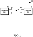
- FIG. 1 illustrates a wireless communication system according to various embodiments of the disclosure.
- FIG. 1 illustrates a transmission end 110 and a reception end 120 as some of nodes using a wireless channel in a wireless communication system.
- FIG. 1 illustrates one transmission end 110 and one reception end 120, a plurality of transmission ends or a plurality of reception ends may be included.
- the transmission end 110 and the reception end 120 are separate entities for convenience of explanation, functions of the transmission end 110 and the reception end 120 may be reversed.
- the transmission end 110 may be a terminal and the reception end 120 may be a base station.
- the transmission end 110 may be a base station and the reception end 120 may be a terminal.
- the base station may be referred to as “access point (AP),” “eNodeB (eNB),” “5G node,” “next generation nodeB (gNB)”, “wireless point,” “transmission/reception point (TRP),” or other terms having the same technical meaning as the above-mentioned terms, in addition to the “base station.”
- the terminal may be referred to as "user equipment (UE),” “mobile station,” “subscriber station,” “remote terminal,” “wireless terminal,” “user device,” or other terms having the same technical meaning as the above-mentioned terms, in addition to the "terminal.”
- the transmission end 110 may identify an inactivation sub-block, may encode data based on the identified sub-block, and may transmit the encoded data to the reception end 120.
- the reception end 120 may receive the encoded data from the transmission end, may identify the inactivation sub-block, and may decode the data based on the identified sub-block.
- FIG. 2 illustrates an example of a configuration of a transmission end device in a wireless communication system according to various embodiments of the disclosure. That is, the configuration illustrated in FIG. 2 may be understood as a configuration of the transmission end 110.
- the term "unit” or terms ending with suffixes "-er,” and “-or” refer to a unit processing at least one function or operation, and may be implemented by hardware, software, or a combination of hardware and software.
- the transmission end 110 may include a communication unit 210, a storage 220, and a controller 230, and the controller 230 may include an inactivation sub-block identification unit 232 and a data encoding unit 234.
- the communication unit 210 may perform functions for transmitting and receiving signals via a wireless channel.
- the communication unit 210 may perform a function of converting between a baseband signal and a bit stream according to a physical layer standard of a system.
- the communication unit 210 may generate complex symbols by encoding and modulating a transmission bit stream.
- the communication unit 210 may restore a reception bit stream by demodulating and decoding a baseband signal.
- the communication unit 210 may up-convert a baseband signal into a radio frequency (RF) band signal, and then may transmit the signal via an antenna, and may down-convert an RF band signal received via an antenna into a baseband signal.
- RF radio frequency
- the communication unit 210 may include a transmission filter, a reception filter, an amplifier, a mixer, an oscillator, a digital to analog converter (DAC), an analog to digital converter (ADC), etc.
- the communication unit 210 may include a plurality of transmission and reception paths.
- the communication unit 210 may include at least one antenna array including a plurality of antenna elements.
- the communication unit 210 may be configured by a digital unit and an analog unit, and the analog unit may be configured by a plurality of sub-units according to operating power, an operating frequency, etc.
- the communication unit 210 may transmit and receive signals as described above. Accordingly, the communication unit 210 may be referred to as a "transmitter,” “receiver,” or “transceiver.” In addition, in the following description, transmitting and receiving via a wireless channel may be used as a meaning including processing by the communication unit 210 as described above. In addition, the communication unit 210 may further include a backhaul communication unit to communicate with other network entities connected through a backhaul network.
- the storage 220 may store data such as a basic program for the operation of the transmission end 110, an application program, configuration information, or the like.
- the storage 220 may be configured by a volatile memory, a nonvolatile memory, or a combination of a volatile memory and a nonvolatile memory.
- the storage 220 may provide stored data according to a request of the controller 230.
- the controller 230 controls overall operations of the transmission end 110.
- the controller 230 may transmit and receive signals via the communication unit 220.
- the controller 230 may write or read out data on or from the storage 230.
- the controller 330 may include at least one processor or a micro processor, or may be a portion of the processor.
- the controller 230 may control operations of respective components included in the communication unit 220.
- the controller 230 may control the inactivation sub-block identification unit 232 and the data encoding unit 234.
- the controller 230 may control the inactivation sub-block identification unit 232 to identify an inactivation sub-block.
- the inactivation sub-block may be determined beforehand and may be stored in the storage 220.
- the controller 230 may control the data encoding unit 234 to encode data based on the identified sub-block.
- the controller 230 may control the transmission end to perform operations according to various embodiments, which will be described below.
- FIG. 3 illustrates an example of a configuration of a reception end device in a wireless communication system according to various embodiments of the disclosure. That is, the configuration illustrated in FIG. 3 may be understood as a configuration of the reception end 120.
- the term "unit” or terms ending with suffixes "-er,” and “-or” used in the following description refer to a unit processing at least one function or operation, and may be implemented by hardware, software, or a combination of hardware and software.
- the reception end 120 may include a communication unit 310, a storage 320, and a controller 330.
- the communication unit 310 may perform functions for transmitting and receiving signals via a wireless channel. For example, the communication unit 310 may perform a function of converting between a baseband signal and a bit stream according to a physical layer standard of a system. For example, when transmitting data, the communication unit 310 may generate complex symbols by encoding and modulating a transmission bit stream. In addition, when receiving data, the communication unit 310 may restore a reception bit stream by demodulating and decoding a baseband signal. In addition, the communication unit 310 may up-convert a baseband signal into an RF band signal, and then may transmit the signal via an antenna, and may down-convert an RF band signal received via an antenna into a baseband signal.
- the communication unit 310 may include a transmission filter, a reception filter, an amplifier, a mixer, an oscillator, a DAC, an ADC, etc.
- the communication unit 310 may include a plurality of transmission and reception paths.
- the communication unit 310 may include at least one antenna array including a plurality of antenna elements.
- the communication unit 310 may be configured by a digital unit and an analog unit, and the analog unit may be configured by a plurality of sub-units according to operating power, an operating frequency, etc.
- the communication unit 310 may transmit and receive signals as described above. Accordingly, the communication unit 310 may be referred to as a "transmitter,” “receiver,” or “transceiver.” In addition, in the following description, transmitting and receiving via a wireless channel may be used as a meaning including processing by the communication unit 310 as described above. In addition, the communication unit 310 may include a backhaul communication unit to communicate with other network entities connected through a backhaul network.
- the storage 320 may store data such as a basic program for the operation of the reception end 120, an application program, configuration information, or the like.
- the storage 320 may be configured by a volatile memory, a nonvolatile memory, or a combination of a volatile memory and a nonvolatile memory.
- the storage 320 may provide stored data according to a request of the controller 330.
- the controller 330 may control overall operations of the reception end 120. For example, the controller 330 may transmit and receive signals via the communication unit 320. In addition, the controller 330 may write and read out data on or from the storage 330. To achieve this, the controller 330 may include at least one processor or a micro processor, or may be a portion of the processor. In other words, the controller 330 may control operations of respective components included in the communication unit 320. According to various embodiments, the controller 330 may control an inactivation sub-block identification unit 332 and a data decoding unit 334. For example, the controller 330 may control the inactivation sub-block identification unit 332 to identify an inactivation sub-block.
- the inactivation sub-block may be determined beforehand and may be stored in the storage 320.
- the reception end 120 may receive information on the inactivation sub-block from the transmission end 110 through the communication unit 310.
- the controller 330 may control the data decoding unit 334 to decode data based on the identified sub-block. The controller 330 may control the reception end to perform operations according to various embodiments, which will be described below.
- An existing polar code may have low encoding and decoding complexity (with reference to successive cancellation (SC) decoding) of O (N log N) if a code length is N. Since the existing polar code thoroughly undergoes a polarization process, the existing polar code is a fully polarized structure where node operations corresponding to all nodes (XOR) are performed. However, technologies for reducing existing operation complexity by reducing unnecessary node operations from among such node operations have been suggested.
- the relaxed polar code technology may utilize reliability of a bit channel as a reference of relaxation.
- the relaxed polar code may asymptotically achieve channel capacity in a binary memoryless symmetric (MBS) channel.
- MCS binary memoryless symmetric
- the relaxed polar code technique may not proceed with polarization anymore when a channel sufficiently becomes better or worse through channel polarization.
- three scenarios may be considered with respect to a sufficiently good, bad channel in a polar code of a finite length.
- a Bhattacharyya parameter is a parameter for determining reliability of a separation channel, and may be defined as an upper bound of a maximum likelihood (ML) error rate when 0 or 1 is transmitted through a channel W.
- the first scenario is a scenario that relaxes sufficiently good channels (good-channel relaxed polarization (GC-RP)).
- GC-RP good-channel relaxed polarization
- T g reference threshold value regarding sufficiently good channels
- the polarization may not proceed anymore and may be stopped.
- the second scenario is a scenario that relaxes sufficiently bad channels (bad-channel relaxed polarization (BC-RP)).
- the third scenario is a scenario that relaxes both sufficiently good channels and sufficiently bad channels (all-channel relaxed polarization (AC-RP)).
- channel polarization may occur as a check node (CN) operation and a variable node (VN) operation of a log likelihood ratio (LLR) are repeatedly performed from a codeword vector end.
- VN variable node
- LLR log likelihood ratio
- polarization units positioned at the right end may not be relaxed if they do not meet a specific threshold value condition.
- the irregular polar code was suggested to overcome restrictions on a reference for selecting a relaxing position at the relaxed polar code.
- inactivation of a polarization unit may be referred to as "relax” in the case of the relaxed polar code, and may be referred to as “inactivation” in the case of the irregular polar code. Since the irregular polar code does not have restrictions on a position of the polarization unit to be inactivate, a polarization unit at any of a source bit end or a codeword end may be inactivated. Therefore, in the case of the irregular polar code, combinations of all polarization units to be inactivated may be considered, and an inactivation pattern having an optimal word error rate (WER) may be selected from these combinations.
- WER word error rate
- P ⁇ is a block error rate when SC decoding is performed
- Z i 0 is the i-th Bhattacharyya parameter value at a source bit end
- K is a set of information bit indexes.
- the WER value when the U(1, 1) polarization unit is inactivated at a binary eraser channel (BEC) the number of information bits of which is 2, the WER value may be 0.2432, when the U(1, 2) polarization unit is inactivated, the WER value may be 0.2383, when the U(2, 1) polarization unit is inactivated, the WER value may be 0.2344, and, when the U(2, 2) polarization unit is inactivated, the WER value may be 0.2383.
- the irregular polar code technique may obtain an inactivation pattern showing the best error rate performance through a greedy search method.
- the relaxed polar code technique may use a threshold value of the Bhattacharyya parameter value indicating reliability of separation channels, and, when the Bhattacharyya parameter value exceeds a reference threshold value or is less than the reference threshold value, this method does not proceed with polarization anymore.
- the irregular polar code technique may enhance a WER and may reduce operation complexity, but may find an inactivation pattern having optimal performance according to the number of inactivated polarization units through an exhaustive search. Therefore, there is a disadvantage that a generator matrix should be newly stored every time and much memory quantity is consumed.
- the disclosure suggests a method for reducing operation complexity without losing performance, by dividing an entire block including a polarization unit into sub-blocks, and inactivating all of node operations in the sub-blocks, in order to overcome the disadvantages of the relaxed polar code technique and the irregular polar code technique described above.
- a source bit may be referred to as an information bit.
- FIG. 4A illustrates an example of a regular polar code method in a wireless communication system according to various embodiments of the disclosure.
- source bits u 0 to u 7 401-1 to 401-8 are calculated through polarization units 402-1 to 402-12, and are encoded into codeword bits x 0 to x 7 403-1 to 403-8.
- FIG. 4A illustrates a regular polar code technique by which bit reversal does not occur if a code length (N) of a polar code is 8.
- N code length
- Such a regular polar code technique may be referred to as a fully polarized structure.
- the block-wise irregular polar code technique suggested in the disclosure provides a concept of a sub-block, and the polar code technique introducing the concept of the sub-block is illustrated in FIGS. 4B and 4C .
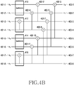
- FIG. 4B illustrates an example of a block-wise polar code method according to a size of a sub-block in a wireless communication system according to various embodiments of the disclosure.
- a size (N sub ) of a sub-block may be defined as 2 t (t ⁇ n) if a size N of an entire block is 2 n .
- n may be 3 and the size of the sub-block may be 1, 2, 4 or 8.
- the size of the-sub-block is 2.
- a transmission end may define sub-blocks 410, 412, 414, and 416 including polarization units. In this case, the transmission end may reduce operation complexity by inactivating at least one of the sub-blocks.
- the transmission end may reduce operation complexity by not performing a node operation with respect to polarization units 402-1 and 402-9 included in the sub-block 410, the sub-block 414, respectively.
- inactivation of sub-blocks may be performed at a position closest to a source vector end. That is, sub-block inactivation may be performed with respect to a sub-block including a polarization unit closest to a source vector end from among polarization units.
- the transmission end inactivates the sub-block 410 and the sub-block 414, such that a node operation is not performed with respect to two polarization units 402-1 and 402-9 from among 12 polarization units in total.
- FIG. 4C illustrates an example of a block-wise polar code method according to a size of a sub-block in a wireless communication system according to various embodiments of the disclosure.
- the size of the sub-block may be 4 and sub-blocks 420 and 422 may be defined.
- the sub-block 420 may include polarization units 402-1, 402-2, 402-4, and 402-6, and the sub-block 422 may include polarization units 402-9, 402-10, 402-11, and 402-12.
- a node operation may not be performed in the polarization units 402-1, 402-2, 402-4, and 402-6.
- decoding corresponding to source bits u 0 to u 3 may be performed at a time.
- LLR values corresponding to u 0 to u 3 before the decoding enters the sub-block 420 may be used directly for decoding of the source bits.
- sorting of inactivation sub-blocks or list decoding is not necessary, operation complexity and a delay time may be reduced.
- the process of encoding and decoding through sub-block inactivation as described above is illustrated in a block diagram of FIG. 5 .
- FIG. 5 illustrates functional configurations of a transmission end and a reception end which perform encoding and decoding of a block-wise polar code in a wireless communication system according to various embodiments of the disclosure.
- An encoding unit 502 illustrated in FIG. 5 may be included in the transmission end 110 of FIG. 1
- a decoding unit 506 may be included in the reception end 120 of FIG. 1 .
- indexes of information bits may be determined based on an index sequence of a polar code, and a code rate.
- An index set 501-1 of the determined information bits may be inputted to the encoding unit 502.
- index information 501-2 of an inactivated sub-block may be inputted to the encoding unit 502.
- the encoding unit 502 may newly define a generator matrix of the polar code, based on the index set 501-1 of the inputted information bits, and the index information 501-2 of the inactivated sub-block.
- G mod modified generator matrix
- a codeword 503 generated by multiplying by the modified matrix generator may pass through a channel 504, and a codeword 505 passing through the channel may be inputted to the decoding unit 506.
- the index set 501-1 of the information bits which has been used for encoding, and the index information 501-2 of the inactivated sub-block may be inputted to the decoding unit 506.
- the decoding unit 506 already knows information on the index set of the information bits and the index information of the inactivated sub-block, the above-described input process may be omitted.
- the decoding unit 506 may decode the codeword 505 passing through the channel, based on the inputted information. Through this, operation complexity may be reduced.
- a specific algorithm of a decoding process of a block-wise irregular polar code technique is as shown in ⁇ Table 1>.
- a transmission end may generate a set of a sequence C in which 1 (on) is displayed with respect to an index included in a set of an information bit index sequence B, and 0 (off) is displayed with respect to an index that is not included in the set of the information bit index sequence B, while increasing indexes from 0 to N-1 on the 3 rd line to the 5 th line of the algorithm.
- the sequence C indicate an on-off vector that displays an information bit as 1 and displays a frozen bit as 0.
- the transmission end may generate an index sequence D of a sub-block to be inactivated on the 8 th line to the 14 th line of the algorithm.
- the transmission end may determine sub-blocks formed only of frozen bits or information bits as inactivation sub-blocks, and may set an element value in a sequence in a sub-block index corresponding to the inactivation sub-blocks to 1.
- the transmission end may set an element value in a sequence in a sub-block index corresponding to the other sub-blocks which are not inactivated to 0.
- the transmission end may update the generator matrix (G), based on the index sequence of the sub-block to be inactivated. That is, the transmission end may update the generator matrix (G N ) of the regular polar code to the modified generator matrix (G mod ).
- the transmission end may acquire the codeword vector (x) by encoding the source bit vector (u) through the modified generator matrix.
- the UpdateGeneratorMatrix (G) function on the 15 th line of ⁇ Table >1 is a function indicating modification of an existing generator matrix according to a method of selecting an inactivated sub-block, and a detailed algorithm thereof is as shown in ⁇ Table 2>.
- the transmission end may define a generator matrix (F), a size of a sub-block (N sub ), and an index (D) of a sub-block to be inactivated.
- the transmission end may divide a size of the generator matrix (len(F)) by the size of the sub-block, and may define the result of division as a size.
- an index k increases from 0 to the number of sub-blocks- 1 (len(D)-1)
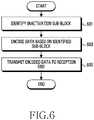
- FIG. 6 is a flowchart of a transmission end which encodes based on an inactivation sub-block in a wireless communication system according to various embodiments of the disclosure.
- FIG. 6 illustrates an example of an operating method of the transmission end 110 of FIG. 1 .
- the transmission end identifies an inactivation sub-block.
- the transmission end may identify an index of a sub-block that is determined to be inactivated according to a method of determining an inactivation sub-block, which will be described below.
- a sub-block formed only of frozen bits may be inactivated regardless of the number of sub-blocks or a decoding method.
- an inactivation method may be different according to a decoding method or reliability of the sub-block.
- the sub-block to be inactivated may be already determined and may be stored in a storage of the transmission end.
- the transmission end encodes data based on the identified sub-block. For example, the transmission end may generate an index sequence of the sub-block to be inactivated, and may determine a modified generator matrix from a generator matrix of a regular polar code, based on the index sequence of the sub-block to be inactivated. The transmission end may encode data by generating a codeword by multiplying the modified generator matrix by an information bit.
- the transmission end transmits the encoded data to a reception end.
- the transmission end may transmit the information bit that is encoded through the modified generator matrix, that is, the codeword, to the reception end.
- the codeword passing through a channel may be received at the reception end, and the codeword may be decoded based on the index of the information bit and the index of the sub-block to be inactivated.
- the transmission end may generate the modified generator matrix reflecting the inactivation of the sub-block prior to encoding the data.
- FIG. 7 illustrates a process of determining a modified generator matrix by identifying an index of an inactivation sub-block.
- FIG. 7 is a flowchart of a transmission end which determines a modified generator matrix in a wireless communication system according to various embodiments of the disclosure.
- FIG. 7 illustrates an operating method of the transmission end 110 of FIG. 1 .
- the transmission end may identify an index set of an inactivation sub-block.
- a size of an index set (D) of a sub-block to be inactivated may be determined based on a code length (N), and a size of a sub-block (N sub ). For example, if the code length is 8 and the size of the sub-block is 2, the size of the index set of the inactivation sub-block may be determined as 4.
- a value of an element corresponding to an index of an inactivated sub-block may be set to 1, and a value of an element corresponding to an index of a sub-block that is not inactivated may be set to 0.
- the transmission end may identify the index set of the inactivation sub-block having such an element.
- the transmission end determines a generator matrix based on the identified index set of the sub-block.
- the transmission end may generate a modified generator matrix by changing a configuration of a normal generator matrix according to a position of an element 1 included in the index set of the inactivation sub-block.
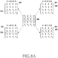
- FIG. 8A illustrates an example of determining a modified generator matrix according to an index of an inactivated sub-block if a size of a sub-block is 2.
- the generator matrix 800 may be modified according to a position of the element 1 included in the index set of the inactivation sub-block. For example, in FIG. 8A , the generator matrix 800 may be modified to four types in total.
- the F 2 matrix of the first row 802 of the generator matrix 800 is replaced with a unit matrix I 2 , such that a modified generator matrix 801 is determined.
- the F 2 matrixes of the second row 804 of the generator matrix 800 are replaced with the unit matrix I 2 , such that a modified generator matrix 803 is determined.
- the F 2 matrixes of the third row 806 of the generator matrix 800 are replaced with the unit matrix I 2 , such that a modified generator matrix 805 is determined.
- the F 2 matrixes of the fourth row 808 of the generator matrix 800 are replaced with the unit matrix I 2 , such that a modified generator matrix 807 is determined.
- the size of the index set of the inactivation sub-block is 2.
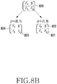
- the generator matrix 820 may be modified according to a position of the element 1 included in the index set of the inactivation sub-block. For example, in FIG. 8B , the generator matrix 820 may be modified in two types in total.
- the F 4 matrix of the first row 822 of the generator matrix 820 is replaced with a unit matrix I 4 , such that a modified generator matrix 821 is determined.
- the F 4 matrixes of the second row 824 of the generator matrix 820 are replaced with the unit matrix I 4 , such that a modified generator matrix 823 is determined.
- the index set of the inactivation sub-block, the modified generator matrix may be already determined and may be stored in the storage of the transmission end.
- the transmission end may encode data by using the determined generator matrix.
- a decoding process performed at a reception end in response to the encoding process of the transmission end will be described with reference to FIG. 9 .
- FIG. 9 is a flowchart of a reception end which decodes based on an inactivation sub-block in a wireless communication system according to various embodiments of the disclosure.
- FIG. 9 illustrates an operating method of the reception end 120 of FIG. 1 .
- the reception end receives encoded data from a transmission end.
- the reception end may receive a codeword transmitted from the transmission end and passing through a channel.
- the codeword may refer to an information bit that is encoded through a modified generator matrix.
- the reception end identifies an inactivation sub-block.
- the reception end may identify an inactivation sub-block based on an index of the inactivation sub-block. For example, if a value of an element included in an inactivation sub-block index set is 1, a sub-block having the corresponding index is an inactivated sub-block, and, if a value of an element included in the inactivation sub-block index set is 0, a sub-block having the corresponding index may be a sub-block that is not inactivated.
- the set including the index of the inactivation sub-block may be pre-stored in a storage of the reception end.
- the transmission end may receive information on the set including the index of the inactivation sub-block from the reception end.
- the reception end decodes data based on the identified sub-block.
- the reception end may perform a check node operation (CN op) or a variable node operation (VN op) based on indexes of source bits, that is, information bits, and may decode data by performing LLR updating based on the index of the sub-block identified as being inactivated.
- CN op check node operation
- VN op variable node operation
- a specific algorithm of a decoding process of a block-wise irregular polar code technique is as shown in ⁇ Table 3>.
- a check node operation in binary expressions of indexes of all information bits (u), a check node operation may be performed with respect to an index corresponding to 0, and a variable node operation may be performed with respect to an index corresponding to 1.
- a check node operation expressed by an f function may be performed with respect to LLR values regarding codeword bits a and b.
- a variable node operation expressed by a g function may be performed with respect to the LLR values regarding the codeword bits a and b.
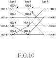
- FIG. 10 is a view illustrating examples of operations of a check node and a variable node in a wireless communication system according to various embodiments of the disclosure.
- codeword bits x 1 to x 4 1003-1 to 1003-4 may be decoded into source bits u 1 to u 4 1001-1 to 1001-4 by passing through stage 2, stage 1, stage 0.
- squares 1002-1, 1002-2, 1002-3, and 1002-4 indicate a check node operation
- circles 1004-1, 1004-2, 1004-3, and 1004-4 indicate a variable node operation.
- indexes of the source bits are expressed by the binary system, ⁇ 00, 01, 10, 11 ⁇ may be expressed for u 1 , u 2 , u 3 , u 4 in sequence.
- the index may indicate a check node operation, and, if the index is 1, the index may indicate a variable node operation.
- the source bit u 1 1001-1 since a check node operation is performed at the check node 1002-1 of the stage 0 with respect to LLR values calculated from the check nodes 1002-2 and 1002-3 of the stage 1, the source bit u 1 1001-1 may be expressed by ⁇ 00 ⁇ .
- the source bit u 2 1001-2 since a variable node operation is performed at the variable node 1004-1 of the stage 0 with respect to LLR values calculated from the check nodes 1002-2 and 1002-3 of the stage 1, the source bit u 2 1001-2 may be expressed by ⁇ 01 ⁇ .
- a function of the check node operation may be defined as shown in ⁇ Equation 2>.
- f a b 2 tanh ⁇ 1 tanh a 2 tanh b 2
- a and b indicate LLR values of codeword bits
- f(a,b) indicates a check node operation function regarding the inputs a and b.
- codeword bits are x 1 and x 2
- a may refer to an LLR value corresponding to the codeword bit x 1
- b may refer to an LLR value corresponding to the codeword bit x 2 .
- a function of the variable node operation may be defined as shown in ⁇ Equation 3>.
- a and b indicate LLR values of codeword bits.
- a may refer to an LLR value corresponding to the codeword bit x 1
- b may refer to an LLR value corresponding to the codeword bit x 2 .
- u refers to a binary bit value for which hard decision is made, and may have a different value at each stage. In various embodiments, u may have 0 or 1.
- g(a,b, u) indicates a variable node operation function if an input is a, b, u.
- LLR values may be updated, and decoding may be performed according to code information of LLR values at the final source bit end, and the presence/absence of a frozen bit or an information bit. That is, as explained on the 14 th line to the 20 th line of ⁇ Table 3>, if a size of a sub-block is already determined, the reception end may update LLR values through a check node or variable node operation from a codeword end toward a source bit end in sequence until a specific stage (log 2 N sub ) comes. In this case, the reception end may stop updating the LLR value with respect to an inactivation sub-block, and may directly determine a source bit value based on an LLR value calculated at the corresponding end.
- the transmission end generates a sequence C that displays 1 (on) with respect to an index included in a set of an information bit index sequence B, and displays 0 (off) with respect to an index that is not included in the set of the information bit index sequence B, while increasing the index from 0 to N-1 on the 4 th line to the 6 th line of the algorithm.
- the sequence C indicates an on-off vector that displays an information bit as 1 and a frozen bit as 0.
- the transmission end may inactivate a sub-block formed only of frozen bits, and, on the 12 th line, may conditionally inactivate a sub-block formed only of information bits. That is, when an SC list decoding technique is used, an inactivation condition for a sub-block formed only of information bits may be added in comparison to an SC decoding technique.
- the transmission end may acquire a sum of the number of all Is of rows of a generator matrix corresponding to bits within a sub-block, that is, a block-degree weight. In this case, a sequence regarding a block-degree weight corresponding to each sub-block may be expressed by E.
- the transmission end may inactivate sub-blocks in sequence from the sub-block having a large block-degree weight.
- the transmission end may inactivate all of the sub-blocks formed only of frozen bits, and may activate a sub-block including both frozen bits and information bits.
- the transmission end may determine a modified generator matrix (G mod ), and may perform data encoding.
- a check node operation in binary expressions of indexes of all information bits (u), a check node operation may be performed with respect to an index corresponding to 0, and a variable node operation may be performed with respect to an index corresponding to 1.
- a check node operation expressed by an f function may be performed with respect to LLR values regarding codeword bits a and b.
- a variable node operation expressed by a g function may be performed with respect to the LLR values regarding the codeword bits a and b.
- the SC list decoding technique is similar to the SC decoding technique, but it may add an index expressed by a path matric and may manage information regarding L number of paths having the highest probability. That is, in the SC decoding technique, the reception end may directly determine 0 or 1 when decoding source bits, but in the SC list decoding technique, the reception end may maintain L number of paths having the highest probability and may decode source bits of the best path passing through a cyclic redundancy check (CRC) from among the remaining paths to the final stage.
- CRC cyclic redundancy check
- the reception end may directly determine source bits as 0 or 1 by using a path matric at a corresponding stage, and, when it is time to process an activation sub-block, the reception end may update the path metric up to the final stage and then may perform final decoding. For example, on the 15 th line of the algorithm of ⁇ Table 5>, the reception end may update a path metric value regarding the L number of best paths. In addition, on the 17 th line to 20 th line, when an element of an inactivation sub-block index set is 1, that is, when there is an inactivation sub-block, the reception end may not perform path metric updating anymore and may determine to decode.
- the decoding determining process is the same as the process described in the 21 st line to the 29 th line of ⁇ Table 3>.
- the reception end may repeat path metric updating.
- a process of encoding and decoding when the SC-list decoding technique is performed will be described below by way of an example.
- a code length N is 8
- a size of a sub-block (N sub ) is 2, and a code rate (R) is 0.5
- an index sequence of a polar code is (0, 1, 2, 4, 3, 5, 6, 7) and a set of an information bit index is ⁇ 3, 5, 6, 7 ⁇
- the index sequence of the polar code expressed by a binary on-off vector may be (0, 0, 0, 1, 0, 1, 1, 1).
- an index set of a sub-block may be defined like ⁇ 0, 1, 2, 3 ⁇ .
- a binary on-off set D expressing inactivation/activation may be defined.
- the index j of the sub-block is an integer satisfying 0 ⁇ j ⁇ 3
- an existing generator matrix may be modified and may be multiplied by a source vector when encoding is performed.
- a check node operation or a variable node operation may be performed three times in total to update an LLR value corresponding to each source bit.
- all node operations for example, 3 times
- a source bit value may be determined.
- the transmission end and the reception end may identify an inactivation sub-block, and accordingly, may perform encoding or decoding.
- methods for determining a sub-block to be inactivated will be described with reference to FIGS. 11 to 18B .
- source bits in such a sub-block may be formed only of frozen bits, may be formed only of information bit, or may be formed of frozen bits and information bits all together.
- a transmission end may inactivate all sub-blocks which are formed only of frozen bits, regardless of the number of sub-blocks or a decoding method.
- a decoding method or reliability of the sub-block should be considered when the sub-block is inactivated.
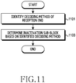
- FIG. 11 which will be described below illustrates a method for determining an inactivation sub-block at a transmission end.
- FIG. 11 is a flowchart of a transmission end which determines an inactivation sub-block in a wireless communication system according to various embodiments of the disclosure.
- FIG. 11 illustrates an operating method of the transmission end 110 of FIG. 1 .
- the transmission end identifies a decoding method of a reception end.
- the transmission end may identify whether a decoding method of the reception end is an SC decoding technique, a CRC-aided SCL (CA-SCL) decoding technique, or a punching-applied CA-SCL decoding technique.
- the reception end may transmit information regarding the decoding technique of the reception end to the transmission end beforehand.
- the decoding technique of the reception end may be already determined, and the transmission end may identify the already determined decoding method of the reception end.
- the transmission end determines an inactivation sub-block based on the identified decoding method. For example, in the case of the SC decoding technique, the transmission end may inactivate a sub-block formed only of frozen bits, and a sub-block formed only of information bits. In the case of the CA-SCL decoding technique, the transmission end may determine an inactivation sub-block by considering a CRC-aided effect. In the case of the puncturing-applied CA-SCL decoding technique, the transmission end may determine an inactivation sub-block by distinguishing between a capacity-0 puncturing technique and a capacity-1 puncturing technique.
- the transmittance end may determine an inactivation sub-block without distinguishing between the capacity-0 puncturing technique and the capacity-1 puncturing technique.
- an inactivation sub-block may be already determined according to a decoding method of the reception end, and may be stored in a storage of the transmission end.
- FIG. 12 is a flowchart of a transmission end which determines an inactivation sub-block when SC decoding is performed in a wireless communication system according to various embodiments of the disclosure.
- FIG. 12 illustrates an operating method of the transmission end 110 of FIG. 1 .
- the transmission end identifies an information bit or a frozen bit included in a sub-block. For example, the transmission end may identify whether only information bits are included in a sub-block, only frozen bits are included in a sub-block, or information bits and frozen bits are included in a sub-block all together.
- FIG. 13A illustrates an example of determining an inactivation sub-block when SC decoding is performed. Referring to FIG. 13A , if a code length is 64, a size of a sub-block is 4, and a code rate is 0.5, 64 source bits u 0 to u 63 1300 may be divided into groups of 4 and may correspond to sub-blocks b 0 to b 15 1312.
- the source bits u 0 to u 63 1300 may be included in the sub-blocks b 0 to b 15 having the size of 4.
- the source bits u 0 to u 3 1302 may correspond to the sub-block bo 1312-1.
- the transmission end may identify whether bits of each sub-block are information bits or frozen bits, with respect to the determined code length and the sub-block. For example, the transmission end may identify the number of information bits 1314 and the number of frozen bits 1316 included in each sub-block 1312, which are shown in table 1310. For example, the transmission end may identify that the number of information bits 1314 included in the sub-block bo is 0, and the number of frozen bits 1316 included in the sub-block bo is 4.
- the transmission end determines an inactivation sub-block according to the identified number of information bits or frozen bits. For example, referring to FIG. 13A , the transmission end may sort the sub-blocks according to an ascending order of the number of information bits 1314, which is shown in table 1320. The transmission end may inactivate sub-blocks b 0 , b 1 , b 2 , b 4 , b 8 1322 that are formed only of frozen bits, and may also inactivate sub-blocks b 7 , b 11 , b 13 , b 14 , b 15 1326 that are formed only of information bits. On the other hand, sub-blocks b 3 , b 5 , b 6 , b 9 , b 10 , b 12 1324 including information bits and frozen bits all together may not be inactivated. That is, they may be activated.
- FIG. 13B illustrates an example of determining an inactivation sub-block when SC decoding is performed.
- the transmission end may identify indexes of source bits 1330, sub-block indexes 1332, states of source bits 1334, degrees of source bits 1336, degrees of sub-blocks 1338, and states of sub-block inactivation 1340.
- the state of the source bit 1334 indicates a frozen bit
- the state is expressed by F
- the state of the source bit indicates an information bit
- the state is expressed by I.
- the degree of the source bit 1336 may refer to the number of Is in a row corresponding to the index 1330 of a corresponding source bit in a generator matrix.
- the index 1330 of the source bit is 0, the number of Is in the first row of the generator matrix G 16 may correspond to the degree of the source bit 1336.
- the degree of the 0-th source bit is 1.
- the degree may be expressed by a row weight sum.
- the degree of the sub-block may refer to a sum of degrees corresponding to the source bits included in the corresponding sub-block.
- the degree of the sub-block may be referred to as a weight of the sub-block.
- the degree 1338 of the 0 th sub-block is 3 which is a sum of 1 and 2.
- the transmission end may identify that the 0 th , 1 st , 2 nd indexes of the sub-block index 1332 include only frozen bits, and the 5 th , 6 th , 7 th indexes include only information bits.
- the transmission end may inactivate the corresponding sub-blocks.
- the transmission end may inactivate the corresponding sub-blocks.
- a corresponding inactivation sub-block may be already determined and may be stored in the storage of the transmission end.
- the transmission end may inactivate sub-blocks formed only of information bits, and sub-blocks formed only of frozen bits, and in this case, performance degradation may not occur.
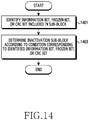
- FIG. 14 illustrates a method for determining an inactivation sub-block when CA-SCL decoding is performed.
- FIG. 14 is a flowchart of a transmission end which determines an inactivation sub-block when CA-SCL decoding is performed in a wireless communication system according to various embodiments of the disclosure.
- FIG. 14 illustrates an operating method of the transmission end 110 of FIG. 1 .
- the transmission end may identify an information bit, a frozen bit, or a CRC bit included in a sub-block. For example, the transmission end may identify whether an information bit, a frozen bit or a CRC bit is included in a corresponding sub-block with respect to the sub-block of a predetermined size.
- the transmission end may determine an inactivation sub-block according to a condition corresponding to the identified information bit, frozen bit, or CRC bit. For example, the transmission end may inactivate a sub-block formed only of frozen bits, and, with respect to a sub-block formed only of information bits, may consider a degree of the sub-block. In addition, when a sub-block formed of information bits and frozen bits is included in a block that has a size two times larger than a current sub-block, the transmission end may not inactivate the current sub-block. In various embodiments, when the decoding method of the transmission end is CA-SCL decoding, a corresponding inactivation sub-block may be already determined, and may be stored in the storage of the transmission end.
- FIGS. 15 to 16B illustrate an example of a bit sequence of a polar code when CRC is aided, and a method for determining an inactivation sub-block.
- FIG. 15 illustrates an example of a bit sequence of a CRC-aided polar code in a wireless communication system according to various embodiments of the disclosure.
- a bit sequence 1500 that is not aided by CRC may include 8 frozen bits 1502 and 8 information bits 1504.
- a bit sequence 1510 is generated.
- the bit sequence 1510 may include 5 frozen bits 1512, 3 CRC bits 1514, and 8 information bits 1516.
- 3 bits having the lowest bit error rate from among the 8 frozen bits, that is, the 3 bits on the rightmost side of the frozen bits, may operate like information bits.
- the bit sequence may be a polarization weight (PW) sequence in the code length of 16.
- PW polarization weight
- the order of the bit sequence may be (0, 1, 2, 4, 8, 3, 5, 6, 9, 10, 12, 7, 11, 13, 14, 15).
- the 8 bits on the head that is, (0, 1, 2, 4, 8, 3, 5, 6) are frozen bits
- the last 3 bits that is, (3, 5, 6) may be indexes of bits operating like information bits when CRC is aided.
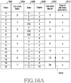
- FIG. 16A illustrates an example of determining an inactivation sub-block when CA-SCL decoding is performed in a wireless communication system according to various embodiments of the disclosure.
- indexes of source bits 1602, sub-block indexes 1604, states of source bits 1606, degrees of source bits 1608, degrees of sub-blocks 1610, and states of sub-block inactivation 1612 if a code length (N) is 16, a code rate (R) is 0.5, and a size of a sub-block (N sub ) is 2 are illustrated.
- the state of the source bit 1606 indicates a frozen bit, the state may be expressed by F, if the state of the source bit indicates an information bit, the state may be expressed by I, and if the state of the source bit indicates a CRC bit, the state may be expressed by CRC.
- the transmission end may identify that the states of the corresponding source bits 1606 are CRC bits which operate like information bits, not like frozen bits. Since the sub-block having the sub-block index 1604 of 0 includes only frozen bits, the transmission end may inactivate the corresponding sub-block. However, since sub-blocks having the sub-block indexes 1604 of 1 and 2 include not only frozen bits but also CRC bits, the transmission end may not inactivate these sub-blocks. In various embodiments, in the case of a sub-block formed only of information bits, the transmission end may consider the degree of the sub-block, that is, a row weight sum.
- the state of the inactivation 1612 of the sub-block formed only of information bits may be determined based on the degree of the sub-block.
- specific sub-block inactivation conditions are as follows.
- the first condition is that the transmission end inactivates the sub-block having the highest degree 1610 of the sub-block, first.
- the second condition is that, if the degrees 1610 of various sub-blocks are the same, the transmission end inactivates the sub-blocks in sequence from the sub-block having the highest sub-block index.
- the third condition is that, if a sub-block including information bits and frozen bits all together is included in a block having a size two times larger than a current sub-block, the transmission end does not inactivate the current sub-block.
- the fourth condition is that, when a sub-block satisfying the third condition is identified, the transmission end does not proceed with sub-block inactivation anymore, and stops inactivating the sub-block. For example, since the sub-block having the sub-block index 1604 of 7 has the highest degree 1610 of the sub-block, 24, the transmission end may inactivate the sub-block having the sub-block index 1604 of 7. An arrow 1614 of FIG. 16A may indicate that sub-block inactivation is determined in order from the highest degree 1610 of the sub-block. In addition, sub-blocks having the sub-block indexes 1604 of 5 and 6 have the same degree of the sub block, 12, but the 6 th sub-block having the higher sub-block index 1604 may be inactivated first.
- the sub-block having the sub-block index 1604 of 5 is formed only of information bits according to the state 1606 of the source bit, and the degree thereof is 12, but the fourth sub-block formed of frozen bits and information bits is included in a block having a size (for example, 4) two time larger than the size (for example, 2) of the current 5 th sub-block. Therefore, the transmission end may not inactivate the 5 th sub-block and may stop inactivating the sub-block.
- FIG. 16B A specific example of the above-described third condition is illustrated in FIG. 16B . Referring to FIG.
- a source bit u 4 1621-1 may be a frozen bit
- a source bit us 1621-2 may be an information bit
- a source bit u 6 1621-3 may be an information bit
- a source bit u 7 1621-4 may be an information bit.
- a sub-block 1624 includes only information bits, but a sub-block 1622 including a frozen bit and an information bit is included in a block having a size (for example, 4) two times larger than a size (for example, 2) of the sub-block 1624. Therefore, the transmission end may not inactivate the sub-block 1624.
- the reason why the transmission end does not inactivate the sub-block 1624 is that, when stages proceed from a source bit end to a code bit end, that is, when a depth is deeper, a node operation may be performed with respect to the frozen bit 1621-1 included in the sub-block 1622 and the information bit 1621-3 included in the sub-block 1624 at the next stage of the stage including the sub-block 1622 and the sub-block 1624. That is, if the node operation for the information bit and the frozen bit can be performed even at the next stage, the transmission end may not inactivate the sub-block including the corresponding information bit or frozen bit.
- an inactivation sub-block may be determined when CA-SCL decoding is performed.
- FIGS. 17 to 18B which will be described below, illustrate a method for determining an inactivation sub-block when puncturing-applied CA-SCL decoding is performed.
- FIG. 17 is a flowchart of a transmission end which determines an inactivation sub-block when puncturing-applied CA-SCL decoding is performed in a wireless communication system according to various embodiments of the disclosure.
- FIG. 17 illustrates an operating method of the transmission end 110 of FIG. 1 .
- the transmission end may identify an information bit, a frozen bit, a CRC bit, or puncturing included in a sub-block. For example, with respect to a sub-block of a predetermined size, the transmission end may identify whether an information bit, a frozen bit, a CRC bit, or puncturing is included in the corresponding sub-block.
- the transmission end may determine an inactivation sub-block according to a condition corresponding to the identified information bit, frozen bit, CRC bit, or puncturing. For example, the transmission end may inactivate a sub-block formed only of frozen bits or a sub-block formed only of puncturing bits. In addition, the transmission end may inactivate a sub-block formed of frozen bits and puncturing bits. In the case of a sub-block formed only of information bits, the transmission end may determine an inactivation sub-block by considering a degree of the sub-block as in CA-SCL decoding. In various embodiments, when a decoding method of the reception end is puncturing-applied CA-SCL decoding, a corresponding inactivation sub-block may already be determined and may be stored in the storage of the transmission end.
- the puncturing technique may be classified into a capacity-0 puncturing technique and a capacity-1 puncturing technique.
- the capacity-0 puncturing technique is a technique by which the transmission end does not transmit some codeword bits to the reception end after polar encoding, and may be referred to as unknown bit puncturing.
- the capacity-1 puncturing technique is a technique by which the transmission end shortens some source bits of the total source bits to 0, and sets the same number of codeword bits related to the shortened source bits to a fixed value, and then does not transmit the source bits to the reception end, and may be referred to as known bit puncturing.
- FIGS. 18A and 18B which will be described below, illustrate an example of determining an inactivation sub-block when an unknown bit is punctured or a known bit is punctured in the puncturing techniques.
- FIG. 18A illustrates an example of determining an inactivation sub-block when an unknown bit is punctured in a wireless communication system according to various embodiments of the disclosure.
- indexes of source bits 1802, sub-block indexes 1804, states of source bits 1806, degrees of source bits 1808, degrees of sub-blocks 1810, and states of inactivation of sub-blocks 1812 if a code length (N) is 16, a size of a sub-block (N sub ) is 2, and the number of CRC bits (nCRC) is 2 are illustrated.
- the state 1806 of the source bit indicates a frozen bit
- the state may be expressed by F
- the state 1806 indicates an information bit
- the state may be expressed by I
- the state 1806 indicates a CRC bit
- the state may be expressed by CRC
- the state 1806 indicates a puncturing bit
- the state may be expressed by Punc.
- the source bits may be punctured in order from the lowest index to the highest index. For example, source bits having the indexes 1802 of 0, 1, 2 may be punctured first.
- the transmission end may inactivate all of the sub-block formed only of puncturing bits, the sub-block formed of puncturing bits and frozen bits, or the sub-block formed only of frozen bits. For example, if the sub-block index 1804 is 0, the states 1806 of the source bits included in the corresponding sub-block all indicate puncturing bits, and accordingly, the transmission end may inactivate the sub-block having the index of 0. In addition, if the sub-block index 1804 is 1, the states 1806 of the source bits included in the corresponding sub-block indicate puncturing bits and frozen bits, and accordingly, the transmission end may inactivate the sub-block having the index of 1.
- the transmission end may inactivate the sub-block having the index of 2.
- the same inactivation sub-block determination method as in CA-SCL may be applied. That is, the first condition is that the transmission end inactivates the sub-block having the highest degree 1810 of the sub-block, first.
- the second condition is that, if the degrees 1810 of various sub-blocks are the same, the transmission end inactivates the sub-blocks in sequence from the sub-block having the highest sub-block index.
- the third condition is that, if a sub-block including information bits and frozen bits all together is included in a block having a size two times larger than a current sub-block, the transmission end does not inactivate the current sub-block. For example, the transmission end may inactivate the 7 th sub-block having the highest degree of the sub-block 1810, 24. In addition, since the 5 th and 6 th sub-blocks have the same degree 1810, 12, the transmission end may inactivate the 6 th sub-block having the higher sub-block index 1804. In the case of the 5 th sub-block, the states 1806 of the source bits included in the 5 th sub-block indicate CRC bits and information bits. In this case, the CRC bit may operate like an information bit.
- the transmission end may not inactivate the 5 th sub-block.
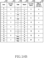
- FIG. 18B illustrates an example of determining an inactivation sub-block when capacity-1 puncturing to which bit-reversal is not applied is performed in a wireless communication system according to various embodiments.
- the state 1826 of the source bit indicates a frozen bit
- the state may be expressed by F
- the state 1826 indicates an information bit
- the state may be expressed by I
- the state 1826 indicates a CRC bit
- the state may be expressed by CRC
- Punc if the state 1826 indicates a puncturing bit
- the source bits may be punctured in order from the highest index to the lowest index. For example, source bits having the indexes 1822 of 13, 14, 15 may be punctured first.
- the transmission end may inactivate a sub-block formed only of frozen bits, first.
- the transmission end may inactivate the sub-block having the index of 0. Since sub-blocks having the 1 st and 2 nd indexes are formed of frozen bits and CRC bits operating like information bits, the transmission end may not inactivate the 1 st and 2 nd sub-blocks. In various embodiments, the transmission end may inactivate a sub-block formed only of puncturing bits. For example, if the sub-block index 1824 is 7, the states 1826 of the source bits included in the corresponding sub-block all indicate puncturing bits, and accordingly, the transmission end may inactivate the sub-block having the index of 7.
- the transmission end may not inactivate the sub-block having the index of 6 and including information bits and puncturing bits.
- the sub-block is formed only of information bits, but the sub-block having the index of 5 and including frozen bits and information bits is included in a block having a size (for example, 4) two times larger than a size (for example, 2) of the sub-block having the index of 5, and accordingly, the transmission end may not inactivate the sub-block having the index of 5.
- the transmission end may not inactivate the sub-block having the index of 3.
- the transmission end may determine an inactivation sub-block when puncturing-applied CA-SCL decoding is performed.
- FIGS. 19A to 20B illustrate scenarios of sub-block inactivation applied to a transmission end and a reception end.
- FIG. 19A is a sequence diagram illustrating a sub-block inactivation procedure at a transmission end and a reception end in a wireless communication system according to various embodiments of the disclosure.
- a transmission end 1902 may refer to the transmission end 110 of FIG. 1
- a reception end 1904 may refer to the reception end 120 of FIG. 1 .
- the transmission end 1902 in the case of an uplink, the transmission end 1902 may refer to a terminal and the reception end 1904 may refer to a base station.
- the transmission end 1902 may refer to a base station and the reception end 1904 may refer to a terminal.
- the transmission end 1902 may refer to a first terminal and the reception end 1904 may refer to a second terminal.
- the transmission end 1902 may inquire of the reception end 1904 whether to apply sub-block inactivation. That is, the transmission end 1902 may transmit a sub-block inactivation application request to the reception end 1904.
- the sub-block inactivation application request may include information regarding a sequence of a sub-block to be inactivated.
- the information regarding the sub-block to be inactivated may be pre-defined and may be stored in a storage of the transmission end 1902.
- the reception end 1904 may apply polar code inactivation.
- the reception end 1904 may identify a sequence of an inactivation sub-block at step 1903-1.
- the reception end 1904 may determine whether to apply polar code inactivation at step 1903-2. That is, the reception end 1904 may determine whether to apply sub-block inactivation.
- the reception end 1904 may respond to the application of the inactivation. That is, when the sub-block inactivation application request transmitted at step 1901 includes the information regarding the sequence of the sub-block to be inactivated, the reception end 1904 may transmit, to the transmission end 1902, a response including information regarding whether the sub-block inactivation is applied.
- the transmission end 1902 and the reception end 1904 may apply polar code sub-block inactivation. That is, when the inactivation application response transmitted by the reception end 1904 includes information indicating that sub-block inactivation is applied, the transmission end 1902 and the reception end 1904 may use the sub-block inactivation when encoding and decoding.
- FIG. 19B is a sequence diagram illustrating a sub-block inactivation procedure at a transmission end and a reception end in a wireless communication system according to various embodiments of the disclosure.
- the transmission end 1902 may refer to the transmission end 110 of FIG. 1
- the reception end 1904 may refer to the reception end 120 of FIG. 1 .
- the transmission end 1902 in the case of an uplink, the transmission end 1902 may refer to a terminal and the reception end 1904 may refer to a base station.
- the transmission end 1902 may refer to a base station and the reception end 1904 may refer to a terminal.
- the transmission end 1902 may refer to a first terminal and the reception end 1902 may refer to a second terminal.
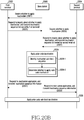
- the transmission end 1902 may inquire of the reception end 1904 whether to apply sub-block inactivation. That is, the transmission end 1902 may transmit a sub-block inactivation application request to the reception end 1904.
- the sub-block inactivation application request may not include information regarding an inactivation sequence.
- information regarding a sub-block to be inactivated may be pre-defined, and may be stored in a storage of the transmission end 1902.
- the reception end 1904 may apply polar code inactivation.
- the reception end 1904 may identify a sequence of an inactivation sub-block at step 1913-1.
- the reception end 1904 may determine whether to apply the polar code inactivation at step 1913-2. That is, the reception end 1904 may determine whether to apply the sub-block inactivation.
- the reception end 1904 may request an inactivation sequence. That is, since the reception end 1904 determines to apply the polar code inactivation at step 1913, but the sub-block inactivation request transmitted at step 1911 does not include information regarding a sequence of a sub-block to be inactivated, the reception end 1904 may transmit a sequence request regarding the sub-block to be inactivated to the transmission end 1902.
- the transmission end 1902 may transmit an inactivation sequence. That is, the transmission end 1902 may transmit a sequence including an index of a sub-block to be inactivated to the reception end 1904 in response to the inactivation sequence request.
- the reception end 1904 may respond to the reception of the inactivation sequence. That is, the reception end 1904 may receive the sequence including the index of the sub-block to be inactivated from the transmission end 1902, and may transmit a response thereto to the transmission end 1902.
- the transmission end 1902 and the reception end 1904 may apply the polar code sub-block inactivation.
- the transmission end 1902 and the reception end 1904 may use the sub-block inactivation when encoding and decoding.
- FIGS. 20A and 20B illustrate an example of applying polar code inactivation when encoding and decoding are performed through signaling procedures of terminals and a base station in the case of communications between terminals.
- FIG. 20A is a sequence diagram illustrating a sub-block inactivation procedure at a transmission end, a reception end and a base station in a wireless communication system according to various embodiments of the disclosure.
- a first terminal 2002 may refer to the transmission end 110 of FIG. 1
- a second terminal 2004 may refer to the reception end 120 of FIG. 1 .
- the first terminal 2002 may transmit its own inactivation sequence list. That is, the first terminal 2002 may transmit a sequence including an index of an inactivation sub-block to a base station 2006. For example, the sequence including the index of the inactivation sub-block may be expressed by a set D.
- the first terminal 2002 may determine a sub-block to be inactivated by identifying a frozen bit, an information bit, or a CRC bit or a puncturing bit included in the sub-block.
- information of the sub-block to be inactivated may be pre-defined and may be stored in a storage of the first terminal 2002.
- the base station 2006 may inquire whether to apply inactivation. That is, the base station 2006 may transmit a message inquiring of the second terminal 2004 whether to apply sub-block inactivation.
- the second terminal 2004 may apply polar code inactivation.
- the second terminal 2004 may identify the inactivation sub-block sequence at step 2005-1.
- the inactivation sub-block sequence may be included in the inactivation application inquiring message transmitted by the base station 2006.
- the second terminal 2004 may determine whether to apply polar code inactivation. That is, the second terminal 2004 may determine whether to apply sub-block inactivation to the identified inactivation sub-block.
- the second terminal 2004 may transmit an inactivation application response to the base station 2006. That is, the second terminal 2004 may transmit a result of determining whether to apply inactivation at step 2005-2 to the base station 2006.
- the base station 2006 may transmit inactivation sequence information to the transmission end 2009. That is, the base station 2006 may transmit, to the first terminal 2002, a response indicating that the corresponding sub-block is used for polar code sub-block inactivation with the terminal 2 2004 with respect to the sequence of the inactivation sub-blocks transmitted by the first terminal 2002 at step 2001.
- the first terminal 2002 and the second terminal 2004 may apply the polar code inactivation. That is, the first terminal 2002 and the second terminal 2004 may use the sub-block inactivation when encoding and decoding.
- FIG. 20B is a sequence diagram illustrating a sub-block inactivation procedure at a transmission end, a reception end, and a base station in a wireless communication system according to various embodiments of the disclosure.
- the first terminal 2002 may refer to the transmission end 110 of FIG. 1
- the second terminal 2004 may refer to the reception end 120 of FIG. 1 .
- the base station 2006 may inquire of the first terminal 2002 whether to apply inactivation. That is, the base station 2006 may transmit a message inquiring whether to apply sub-block inactivation to the first terminal 2002.
- the first terminal 2002 may transmit a response to the inquiry about whether inactivation is applied, and its own inactivation sequence list. That is, the first terminal 2002 may transmit a response to the inquiry about whether sub-block inactivation is applied to the base station 2006, and may transmit a sequence including an index of an inactivation sub-block.
- the sequence including the index of the inactivation sub-block which is usable at the first terminal 2002 may be pre-defined and may be stored in a storage of the terminal 1 2002.
- the first terminal 2002 may transmit only the response to the inquiry about whether inactivation is applied to the base station 2006.
- the base station 2006 may inquire of the second terminal 2004 whether to apply inactivation. That is, the base station 2006 may transmit a message inquiring whether to apply sub-block inactivation to the second terminal 2004.
- the second terminal 2004 may transmit a response to the inquiry about whether inactivation is applied, and its own inactivation sequence list. That is, the second terminal 2004 may transmit a response to the inquiry about whether sub-block inactivation is applied to the base station 2006, and may transmit a sequence including an index of an inactivation sub-block.
- the sequence including the index of the inactivation sub-block which is usable at the second terminal 2004 may be pre-defined, and may be stored in a storage of the second terminal 2004.
- the second terminal 2004 may transmit only the response to the inquiry about whether inactivation is applied to the base station 2006.
- the base station 2006 may apply polar code inactivation.
- the base station 2006 may identify the inactivation sub-block sequence at step 2029-1.
- the inactivation sub-block sequence may be received from the first terminal 2002 at step 2023, or may be received from the second terminal 2004 at step 2027. That is, the base station 2006 may identify the index of the inactivation sub-block usable at the first terminal 2002, and the index of the inactivation sub-block usable at the second terminal 2004.
- the base station 2006 may directly determine an inactivation sub-block, or may identify an index of an inactivation sub block predetermined.
- the base station 2006 may determine whether to apply polar code inactivation. That is, the base station 2006 may identify an index of an inactivation sub-block which is usable both by the first terminal 2002 and by the second terminal 2004, based on the index of the inactivation sub-block identified as being usable at the first terminal 2002 at step 2005-1, and the index of the inactivation sub-block usable at the second terminal 2004, and may determine this as an inactivation sub-block. In an embodiment, when the inactivation sub-block usable at the first terminal 2002 and the inactivation sub-block usable at the second terminal 2004 are different, the base station 2006 may determine that the polar code sub-block inactivation is not applicable to the first terminal 2002 and the second terminal 2004.
- the base station 2006 may transmit an inactivation application response and inactivation sequence information to the first terminal 2002. That is, the base station 2006 may transmit information on the inactivation sub-block determined at step 2029-2 to the first terminal 2002. However, when the base station 2006 determines that polar code sub-block inactivation is not applicable, the base station 2006 may transmit corresponding information to the first terminal 2002.
- the base station 2006 may transmit an inactivation application response and inactivation sequence information to the second terminal 2004. That is, the base station 2006 may transmit information regarding the inactivation sub-block determined at step 2029-2 to the second terminal 2004. However, when the base station 2006 determines that polar code sub-block inactivation is not applicable, the base station 2006 may transmit corresponding information to the second terminal 2004.
- the first terminal 2002 and the second terminal 2004 may apply polar code inactivation. That is, the first terminal 2002 and the second terminal 2004 may apply sub-block inactivation when encoding and decoding, based on the information on the inactivation sub-block which is usable both at the first terminal 2002 and at the second terminal 2004, and which is received from the base station. In an embodiment, when the base station 2006 determines that polar code sub-block inactivation is not applicable, the first terminal 2002 and the second terminal 2004 may not apply polar code sub-block inactivation when encoding and decoding, although this operation is not illustrated in FIG. 20B .
- FIGS. 21A to 23B which will be described hereinbelow, illustrate graphs comparing block error rate (BLER) performance when sub-block inactivation described in the disclosure is applied, and SC decoding, SC-list decoding, and CA-SCL decoding is performed.
- BLER block error rate
- FIG. 21A illustrates a graph illustrating BLER performance when SC decoding is performed in a wireless communication system according to various embodiments of the disclosure.
- FIG. 21A is a graph comparing BLER performance according to E b /N 0 with respect to various code rates if a code length (N) is 128 and a size of a sub-block (N sub ) is 2.
- performance of related-art SC decoding is similar to each other.
- a BLER in a simulation 1 where the SC decoding technique is applied and a BLER in a simulation 2 where the block-wise decoding technique of the disclosure is applied may be similar to each other.
- a BLER in a simulation 3 where the SC decoding technique is applied and a BLER in a simulation 4 where the block-wise decoding technique of the disclosure is applied may be similar to each other.
- the reduction rate in the number of operations according to a ratio of an inactivation sub-block is explained under the same condition.
- the reduction rate in the number of operations is about 15%.
- FIG. 21B illustrates a graph illustrating BLER performance when SC decoding is performed in a wireless communication system according to various embodiments of the disclosure.
- FIG. 21B is a graph comparing BLER performance according to E b /N 0 with respect to various code rates if a code length (N) is 128 and a size of a sub-block (N sub ) is 4.
- performance of related-art SC decoding is similar to each other.
- a BLER in a simulation 1 where the SC decoding technique is applied and a BLER in a simulation 2 where the block-wise decoding technique of the disclosure is applied may be similar to each other.
- a BLER in a simulation 3 where the SC decoding technique is applied and a BLER in a simulation 4 where the block-wise decoding technique of the disclosure is applied may be similar to each other.
- a BLER in a simulation 5 where the SC decoding technique is applied, and a BLER in a simulation 6 where the block-wise decoding technique of the disclosure is applied may be similar to each other.
- ⁇ Table 7> in the case of the related-art SC decoding technique, the block-wise decoding technique of the disclosure, the reduction rate in the number of operations according to a ratio of an inactivation sub-block is explained under the same condition. Comparing the case of ⁇ Table 6> where the size of the sub-block is 2, table 7 shows that the number of operations is further reduced by about 3% to 7%, and almost similar decoding performance to that of the related-art SC decoding technique is exhibited.
- FIG. 21C illustrates a graph illustrating BLER performance when SC decoding is performed in a wireless communication system according to various embodiments of the disclosure.
- FIG. 21C is a graph comparing BLER performance according to E b /N 0 with respect to various code rates when binary phase shift keying (BPSK) modulation is used if a code length (N) is 2048 and a size of a sub-block (N sub ) is 16.
- BPSK binary phase shift keying
- performance of related-art SC decoding is similar to each other.
- a BLER in a simulation 1 where the SC decoding technique is applied and a BLER in a simulation 2 where the block-wise decoding technique of the disclosure is applied may be similar to each other.
- a BLER in a simulation 3 where the SC decoding technique is applied and a BLER in a simulation 4 where the block-wise decoding technique of the disclosure is applied may be similar to each other.
- a BLER in a simulation 5 where the SC decoding technique is applied, and a BLER in a simulation 6 where the block-wise decoding technique of the disclosure is applied may be similar to each other.
- the reduction rate in the number of operations according to a ratio of an inactivation sub-block is explained under the same condition.
- performance degradation may not occur.
- the reduction rate in operations achieved through inactivation of sub-blocks increases as the code rate increases.
- FIG. 21D illustrates a graph illustrating BLER performance when SC decoding is performed in a wireless communication system according to various embodiments of the disclosure.
- FIG. 21D is a graph comparing BLER performance according to E b /N 0 with respect to various code rates when binary phase shift keying (BPSK) modulation is used if a code length (N) is 2048 and a size of a sub-block (N sub ) is 32.
- BPSK binary phase shift keying
- performance of related-art SC decoding is similar to each other.
- a BLER in a simulation 1 where the SC decoding technique is applied and a BLER in a simulation 2 where the block-wise decoding technique of the disclosure is applied may be similar to each other.
- a BLER in a simulation 3 where the SC decoding technique is applied and a BLER in a simulation 4 where the block-wise decoding technique of the disclosure is applied may be similar to each other.
- a BLER in a simulation 5 where the SC decoding technique is applied, and a BLER in a simulation 6 where the block-wise decoding technique of the disclosure is applied may be similar to each other.
- Block-wise decoding 7 25 50% 19915 R 1/2 Normal decoding - - - 25600 20.6%
- R 3/4 Normal decoding - - - - 26112 26.6%
- a sub-block when a CA-SCL decoding technique is used, a sub-block may be inactivated according to a different criterion from when the SC decoding technique is used. For example, a transmission end may inactivate sub-blocks formed only of frozen bits, first. When inactivating sub-blocks formed only of information bits, the transmission end may inactivate the sub-blocks in order from the sub-block of the highest degree, and, when the degrees of various sub-blocks are the same, the transmission end may inactivate sub-blocks in order from the sub-block having the highest index.
- the transmission end may not inactivate the current sub-block.
- BLER performance of CA-SCL decoding when the above-described inactivation sub-block determination criterion is applied will be described in FIGS. 22A to 22B .
- FIG. 22A illustrates a graph illustrating BLER performance when CA-SCL decoding is performed in a wireless communication system according to various embodiments of the disclosure.
- FIG. 22A is a graph comparing BLER performance according to E b /N 0 with respect to various code rates if a code length (N) is 128, a size of a sub-block (N sub ) is 2, a size of a list is 8, and CRC is 8 bits.
- performance of related-art CA-SCL decoding are similar to each other.
- a BLER in a simulation 1 where the CA-SCL decoding technique is applied and a BLER in a simulation 2 where the block-wise decoding technique of the disclosure is applied may be similar to each other.
- a BLER in a simulation 3 where the CA-SCL decoding technique is applied and a BLER in a simulation 4 where the block-wise decoding technique of the disclosure is applied may be similar to each other.
- the reduction rate in the number of operations according to a ratio of an inactivation sub-block is explained under the same condition. That is, when CA-SCL decoding is performed and the sub-block-wise decoding technique of the disclosure is used, the reduction rate in the number of operations may increase to 24.09%, 25.52%, 35.67% as the code rate increases to 1/3, 1/2, 3/4.
- FIG. 22B illustrates a graph illustrating BLER performance when CA-SCL decoding is performed in a wireless communication system according to various embodiments of the disclosure.
- FIG. 22B is a graph comparing BLER performance according to E b /N 0 with respect to various code rates if a code length (N) is 2048, a size of a sub-block (N sub ) is 16, a size of a list is 8, and CRC is 16 bits.
- performance of related-art CA-SCL decoding are similar to each other.
- a BLER in a simulation 1 where the CA-SCL decoding technique is applied and a BLER in a simulation 2 where the block-wise decoding technique of the disclosure is applied may be similar to each other.
- a BLER in a simulation 3 where the CA-SCL decoding technique is applied and a BLER in a simulation 4 where the block-wise decoding technique of the disclosure is applied may be similar to each other.
- a BLER in a simulation 5 where the CA-SCL decoding technique is applied, and a BLER in a simulation 6 where the block-wise decoding technique of the disclosure is applied may be similar to each other.
- the reduction rate in the number of operations according to a ratio of an inactivation sub-block is explained under the same condition. That is, when CA-SCL decoding is performed and the sub-block-wise decoding technique of the disclosure is used, the reduction rate in the number of operations may increase to 18.27%, 21.24%, 31.99% as the code rate increases to 1/3, 1/2, 3/4.
- FIG. 23A illustrates a graph illustrating BLER performance when CA-SCL decoding to which capacity-0 puncturing is applied is performed in a wireless communication system according to various embodiments of the disclosure.
- FIG. 23A is a graph comparing BLER performance according to E b /N 0 if a code length (N) is 128, a size of a sub-block (N sub ) is 2, a size of a list is 4, and CRC is 8 bits.
- performance of decoding of related-art unknown bit puncturing are similar to each other.
- a BLER in a simulation 1 where the unknown bit puncturing decoding technique is applied and a BLER in a simulation 2 where the block-wise decoding technique of the disclosure is applied may be similar to each other.
- a node operation may not be performed within a sub-block through the same sub-block inactivation determining method as in the above-described CA-SCL decoding.
- the reduction rate in the number of operations according to a ratio of an inactivation sub-block is explained under the same condition. That is, when CA-SCL decoding to which unknown bit puncturing is applied is performed, and the sub-block-wise decoding technique of the disclosure is used, the reduction rate in the number of operations is 18.97% at the code rate of 1/2, and operation complexity may be lower than in the normal decoding technique.
- FIG. 23B illustrates a graph illustrating BLER performance when CA-SCL decoding to which puncturing is applied is performed in a wireless communication system according to various embodiments of the disclosure.
- FIG. 23B is a graph comparing BLER performance according to E b /N 0 if a code length (N) is 128, a size of a sub-block (N sub ) is 2, a size of a list is 4, and CRC is 8 bits.
- performance of decoding by applying a related-art shortening technique are similar to each other.
- a BLER in a simulation 1 where the related-art shortening technique is applied and a BLER in a simulation 2 where the block-wise decoding technique of the disclosure is applied may be similar to each other.
- a node operation may not be performed within a sub-block through the same sub-block inactivation determining method as in the above-described CA-SCL decoding.
- the reduction rate in the number of operations according to a ratio of an inactivation sub-block is explained under the same condition. That is, when CA-SCL decoding to which shortening is applied is performed, and the sub-block-wise decoding technique of the disclosure is used, the reduction rate in the number of operations is 23.26% at the code rate of 1/2, and operation complexity may be lower than in the normal decoding technique.
- operation complexity can be reduced in various decoding techniques including SC decoding, CA-SCL decoding, and CA-SCL decoding to which puncturing or shortening is applied.
- a computer readable storage medium for storing one or more programs (software modules) may be provided.
- the one or more programs stored in the computer readable storage medium are configured for execution performed by one or more processors in an electronic device.
- the one or more programs include instructions for allowing the electronic device to execute the methods based on the claims or the embodiments disclosed in the disclosure.
- the program (the software module or software) may be stored in a random access memory, a non-volatile memory including a flash memory, a read only memory (ROM), an electrically erasable programmable read only memory (EEPROM), a magnetic disc storage device, a compact disc-ROM (CD-ROM), digital versatile discs (DVDs) or other forms of optical storage devices, and a magnetic cassette.
- a non-volatile memory including a flash memory, a read only memory (ROM), an electrically erasable programmable read only memory (EEPROM), a magnetic disc storage device, a compact disc-ROM (CD-ROM), digital versatile discs (DVDs) or other forms of optical storage devices, and a magnetic cassette.
- the program may be stored in a memory configured in combination of all or some of these storage media.
- the configured memory may be plural in number.
- the program may be stored in an attachable storage device capable of accessing the electronic device through a communication network such as the Internet, an Intranet, a local area network (LAN), a wide LAN (WLAN), or a storage area network (SAN) or a communication network configured by combining the networks.
- the storage device may access via an external port to a device which performs the embodiments of the disclosure.
- an additional storage device on a communication network may access to a device which performs the embodiments of the disclosure.
Landscapes
- Physics & Mathematics (AREA)
- Probability & Statistics with Applications (AREA)
- Engineering & Computer Science (AREA)
- Theoretical Computer Science (AREA)
- Mathematical Physics (AREA)
- Mobile Radio Communication Systems (AREA)
Applications Claiming Priority (2)
| Application Number | Priority Date | Filing Date | Title |
|---|---|---|---|
| KR1020180115862A KR102709506B1 (ko) | 2018-09-28 | 2018-09-28 | 무선 통신 시스템에서 극 부호를 이용한 부호화 및 복호화를 위한 장치 및 방법 |
| PCT/KR2019/009096 WO2020067637A1 (ko) | 2018-09-28 | 2019-07-23 | 무선 통신 시스템에서 극 부호를 이용한 부호화 및 복호화를 위한 장치 및 방법 |
Publications (3)
| Publication Number | Publication Date |
|---|---|
| EP3859979A1 true EP3859979A1 (de) | 2021-08-04 |
| EP3859979A4 EP3859979A4 (de) | 2021-11-03 |
| EP3859979B1 EP3859979B1 (de) | 2023-12-06 |
Family
ID=69952213
Family Applications (1)
| Application Number | Title | Priority Date | Filing Date |
|---|---|---|---|
| EP19866763.6A Active EP3859979B1 (de) | 2018-09-28 | 2019-07-23 | Vorrichtung und verfahren zur codierung und decodierung unter verwendung eines polaren codes in einem drahtloskommunikationssystem |
Country Status (4)
| Country | Link |
|---|---|
| US (1) | US11451244B2 (de) |
| EP (1) | EP3859979B1 (de) |
| KR (1) | KR102709506B1 (de) |
| WO (1) | WO2020067637A1 (de) |
Cited By (1)
| Publication number | Priority date | Publication date | Assignee | Title |
|---|---|---|---|---|
| WO2022192717A1 (en) * | 2021-03-12 | 2022-09-15 | Idac Holdings, Inc. | Methods and procedures for crc aided encoding and bp decoding for polar codes |
Families Citing this family (5)
| Publication number | Priority date | Publication date | Assignee | Title |
|---|---|---|---|---|
| WO2018187902A1 (en) | 2017-04-10 | 2018-10-18 | Qualcomm Incorporated | An efficient interleaver design for polar codes |
| CN113541698B (zh) * | 2020-04-22 | 2022-07-12 | 华为技术有限公司 | 编码、译码方法、装置及设备 |
| CN120320781A (zh) * | 2020-06-17 | 2025-07-15 | 华为技术有限公司 | Polar码编码方法、Polar码译码方法及其装置 |
| EP4513765A1 (de) * | 2023-08-25 | 2025-02-26 | Tannera Technologies doo | Optimierungen von speichernutzungs- und parity check matrix-verarbeitungsplänen für einen geschichteten ldpc-decodierer |
| KR20250093871A (ko) * | 2023-12-18 | 2025-06-25 | 삼성전자주식회사 | 무선 통신 및 방송 시스템에서 채널 부호의 앙상블 복호 방법 및 장치 |
Family Cites Families (11)
| Publication number | Priority date | Publication date | Assignee | Title |
|---|---|---|---|---|
| JP4224022B2 (ja) * | 2002-06-11 | 2009-02-12 | デジタル ファウンテン, インコーポレイテッド | イナクティブ化によって連鎖反応符号を復号化するためのシステムおよび処理 |
| US9419749B2 (en) * | 2009-08-19 | 2016-08-16 | Qualcomm Incorporated | Methods and apparatus employing FEC codes with permanent inactivation of symbols for encoding and decoding processes |
| KR101678053B1 (ko) * | 2010-04-02 | 2016-11-22 | 삼성전자 주식회사 | 반도체 장치 및 이의 복호 방법 |
| US9629005B2 (en) * | 2015-04-07 | 2017-04-18 | Pismo Labs Technology Limited | Systems and methods providing assisted aiming for wireless links |
| US10199726B2 (en) * | 2011-06-29 | 2019-02-05 | Pismo Labs Technology Limited | Systems and methods providing assisted aiming for wireless links through a plurality of external antennas |
| US9055455B2 (en) * | 2011-06-29 | 2015-06-09 | Pismo Labs Technology Ltd. | Systems and methods providing assisted aiming for wireless links |
| US9504042B2 (en) | 2014-05-28 | 2016-11-22 | Samsung Electronics Co., Ltd. | System and method for encoding and decoding of data with channel polarization mechanism |
| CN108370255B (zh) | 2015-11-24 | 2022-04-12 | 相干逻辑公司 | 极性码连续消去列表解码器中的存储器管理和路径排序 |
| TW201733322A (zh) | 2015-12-14 | 2017-09-16 | Idac控股公司 | 使用極化碼凍結位元之wtru識別 |
| US10313056B2 (en) * | 2017-02-06 | 2019-06-04 | Mitsubishi Electric Research Laboratories, Inc. | Irregular polar code encoding |
| WO2019032002A1 (en) * | 2017-08-10 | 2019-02-14 | Telefonaktiebolaget Lm Ericsson (Publ) | METHODS OF RESPONSE TO SCG FAILURE IN WIRELESS DC AND TERMINAL COMMUNICATIONS AND ASSOCIATED TERMINALS AND NETWORK NODES |
-
2018
- 2018-09-28 KR KR1020180115862A patent/KR102709506B1/ko active Active
-
2019
- 2019-07-23 EP EP19866763.6A patent/EP3859979B1/de active Active
- 2019-07-23 WO PCT/KR2019/009096 patent/WO2020067637A1/ko not_active Ceased
- 2019-07-23 US US17/277,041 patent/US11451244B2/en active Active
Cited By (2)
| Publication number | Priority date | Publication date | Assignee | Title |
|---|---|---|---|---|
| WO2022192717A1 (en) * | 2021-03-12 | 2022-09-15 | Idac Holdings, Inc. | Methods and procedures for crc aided encoding and bp decoding for polar codes |
| US12200538B2 (en) | 2021-03-12 | 2025-01-14 | Interdigital Patent Holdings, Inc. | Methods and procedures for CRC aided encoding and BP decoding for polar codes |
Also Published As
| Publication number | Publication date |
|---|---|
| EP3859979A4 (de) | 2021-11-03 |
| US20210281279A1 (en) | 2021-09-09 |
| KR102709506B1 (ko) | 2024-09-25 |
| EP3859979B1 (de) | 2023-12-06 |
| US11451244B2 (en) | 2022-09-20 |
| KR20200036338A (ko) | 2020-04-07 |
| WO2020067637A1 (ko) | 2020-04-02 |
Similar Documents
| Publication | Publication Date | Title |
|---|---|---|
| EP3859979B1 (de) | Vorrichtung und verfahren zur codierung und decodierung unter verwendung eines polaren codes in einem drahtloskommunikationssystem | |
| US11095397B2 (en) | Apparatus and method for encoding and decoding using polar code in wireless communication system | |
| EP3510700B1 (de) | Verfahren und vorrichtung zur codierung von daten unter verwendung eines polaren codes | |
| RU2716044C1 (ru) | Способы и системы кодирования и декодирования ldpc кодов | |
| CN107342845B (zh) | 一种速率匹配的方法和装置 | |
| US10833706B2 (en) | Polar encoding and decoding using predefined information | |
| US10735138B2 (en) | Multi-label offset lifting method | |
| US11133828B2 (en) | Coding method and apparatus | |
| KR20170074684A (ko) | 무선 통신 시스템에서 부호화를 위한 장치 및 방법 | |
| US11374680B2 (en) | Method and apparatus for performing encoding and decoding in wireless communication system | |
| US11936400B2 (en) | Method and apparatus for encoding and decoding polar code | |
| US12273197B2 (en) | Method for determining auxiliary bit of polar code and apparatus | |
| US11005596B2 (en) | Apparatus and method for determining polar code in wireless communication system | |
| EP4529057A1 (de) | Datenverarbeitungsverfahren, elektronische vorrichtung und computerlesbares speichermedium | |
| US12143125B2 (en) | Polarization encoding method and apparatus | |
| JP7030932B2 (ja) | Ldpc符号の符号化および復号化のための方法およびシステム | |
| CN116667861A (zh) | 基于极化码的编码方法和编码装置 | |
| CN107360626A (zh) | 通信方法及其网络设备、用户设备 | |
| KR20260035594A (ko) | 무선 통신 시스템에서 부호율 정합 극부호를 위한 부호화 다이버시티 방법 및 장치 | |
| CN120283370A (zh) | 级联编码方法、级联译码方法及装置 |
Legal Events
| Date | Code | Title | Description |
|---|---|---|---|
| STAA | Information on the status of an ep patent application or granted ep patent |
Free format text: STATUS: THE INTERNATIONAL PUBLICATION HAS BEEN MADE |
|
| PUAI | Public reference made under article 153(3) epc to a published international application that has entered the european phase |
Free format text: ORIGINAL CODE: 0009012 |
|
| STAA | Information on the status of an ep patent application or granted ep patent |
Free format text: STATUS: REQUEST FOR EXAMINATION WAS MADE |
|
| 17P | Request for examination filed |
Effective date: 20210427 |
|
| AK | Designated contracting states |
Kind code of ref document: A1 Designated state(s): AL AT BE BG CH CY CZ DE DK EE ES FI FR GB GR HR HU IE IS IT LI LT LU LV MC MK MT NL NO PL PT RO RS SE SI SK SM TR |
|
| A4 | Supplementary search report drawn up and despatched |
Effective date: 20211001 |
|
| RIC1 | Information provided on ipc code assigned before grant |
Ipc: H03M 13/29 20060101ALI20210927BHEP Ipc: H03M 13/09 20060101ALI20210927BHEP Ipc: H03M 13/11 20060101ALI20210927BHEP Ipc: H03M 13/00 20060101ALI20210927BHEP Ipc: H03M 13/13 20060101AFI20210927BHEP |
|
| DAV | Request for validation of the european patent (deleted) | ||
| DAX | Request for extension of the european patent (deleted) | ||
| GRAP | Despatch of communication of intention to grant a patent |
Free format text: ORIGINAL CODE: EPIDOSNIGR1 |
|
| STAA | Information on the status of an ep patent application or granted ep patent |
Free format text: STATUS: GRANT OF PATENT IS INTENDED |
|
| INTG | Intention to grant announced |
Effective date: 20230725 |
|
| GRAS | Grant fee paid |
Free format text: ORIGINAL CODE: EPIDOSNIGR3 |
|
| GRAA | (expected) grant |
Free format text: ORIGINAL CODE: 0009210 |
|
| STAA | Information on the status of an ep patent application or granted ep patent |
Free format text: STATUS: THE PATENT HAS BEEN GRANTED |
|
| RAP3 | Party data changed (applicant data changed or rights of an application transferred) |
Owner name: RESEARCH & BUSINESS FOUNDATION SUNGKYUNKWAN UNIVERSITY Owner name: SAMSUNG ELECTRONICS CO., LTD. |
|
| AK | Designated contracting states |
Kind code of ref document: B1 Designated state(s): AL AT BE BG CH CY CZ DE DK EE ES FI FR GB GR HR HU IE IS IT LI LT LU LV MC MK MT NL NO PL PT RO RS SE SI SK SM TR |
|
| REG | Reference to a national code |
Ref country code: GB Ref legal event code: FG4D |
|
| REG | Reference to a national code |
Ref country code: CH Ref legal event code: EP |
|
| REG | Reference to a national code |
Ref country code: DE Ref legal event code: R096 Ref document number: 602019042988 Country of ref document: DE |
|
| REG | Reference to a national code |
Ref country code: IE Ref legal event code: FG4D |
|
| REG | Reference to a national code |
Ref country code: LT Ref legal event code: MG9D |
|
| PG25 | Lapsed in a contracting state [announced via postgrant information from national office to epo] |
Ref country code: GR Free format text: LAPSE BECAUSE OF FAILURE TO SUBMIT A TRANSLATION OF THE DESCRIPTION OR TO PAY THE FEE WITHIN THE PRESCRIBED TIME-LIMIT Effective date: 20240307 |
|
| REG | Reference to a national code |
Ref country code: NL Ref legal event code: MP Effective date: 20231206 |
|
| PG25 | Lapsed in a contracting state [announced via postgrant information from national office to epo] |
Ref country code: LT Free format text: LAPSE BECAUSE OF FAILURE TO SUBMIT A TRANSLATION OF THE DESCRIPTION OR TO PAY THE FEE WITHIN THE PRESCRIBED TIME-LIMIT Effective date: 20231206 |
|
| PG25 | Lapsed in a contracting state [announced via postgrant information from national office to epo] |
Ref country code: ES Free format text: LAPSE BECAUSE OF FAILURE TO SUBMIT A TRANSLATION OF THE DESCRIPTION OR TO PAY THE FEE WITHIN THE PRESCRIBED TIME-LIMIT Effective date: 20231206 |
|
| PG25 | Lapsed in a contracting state [announced via postgrant information from national office to epo] |
Ref country code: LT Free format text: LAPSE BECAUSE OF FAILURE TO SUBMIT A TRANSLATION OF THE DESCRIPTION OR TO PAY THE FEE WITHIN THE PRESCRIBED TIME-LIMIT Effective date: 20231206 Ref country code: GR Free format text: LAPSE BECAUSE OF FAILURE TO SUBMIT A TRANSLATION OF THE DESCRIPTION OR TO PAY THE FEE WITHIN THE PRESCRIBED TIME-LIMIT Effective date: 20240307 Ref country code: ES Free format text: LAPSE BECAUSE OF FAILURE TO SUBMIT A TRANSLATION OF THE DESCRIPTION OR TO PAY THE FEE WITHIN THE PRESCRIBED TIME-LIMIT Effective date: 20231206 Ref country code: BG Free format text: LAPSE BECAUSE OF FAILURE TO SUBMIT A TRANSLATION OF THE DESCRIPTION OR TO PAY THE FEE WITHIN THE PRESCRIBED TIME-LIMIT Effective date: 20240306 |
|
| REG | Reference to a national code |
Ref country code: AT Ref legal event code: MK05 Ref document number: 1639362 Country of ref document: AT Kind code of ref document: T Effective date: 20231206 |
|
| PG25 | Lapsed in a contracting state [announced via postgrant information from national office to epo] |
Ref country code: NL Free format text: LAPSE BECAUSE OF FAILURE TO SUBMIT A TRANSLATION OF THE DESCRIPTION OR TO PAY THE FEE WITHIN THE PRESCRIBED TIME-LIMIT Effective date: 20231206 |
|
| PG25 | Lapsed in a contracting state [announced via postgrant information from national office to epo] |
Ref country code: SE Free format text: LAPSE BECAUSE OF FAILURE TO SUBMIT A TRANSLATION OF THE DESCRIPTION OR TO PAY THE FEE WITHIN THE PRESCRIBED TIME-LIMIT Effective date: 20231206 Ref country code: RS Free format text: LAPSE BECAUSE OF FAILURE TO SUBMIT A TRANSLATION OF THE DESCRIPTION OR TO PAY THE FEE WITHIN THE PRESCRIBED TIME-LIMIT Effective date: 20231206 Ref country code: NO Free format text: LAPSE BECAUSE OF FAILURE TO SUBMIT A TRANSLATION OF THE DESCRIPTION OR TO PAY THE FEE WITHIN THE PRESCRIBED TIME-LIMIT Effective date: 20240306 Ref country code: NL Free format text: LAPSE BECAUSE OF FAILURE TO SUBMIT A TRANSLATION OF THE DESCRIPTION OR TO PAY THE FEE WITHIN THE PRESCRIBED TIME-LIMIT Effective date: 20231206 Ref country code: LV Free format text: LAPSE BECAUSE OF FAILURE TO SUBMIT A TRANSLATION OF THE DESCRIPTION OR TO PAY THE FEE WITHIN THE PRESCRIBED TIME-LIMIT Effective date: 20231206 Ref country code: HR Free format text: LAPSE BECAUSE OF FAILURE TO SUBMIT A TRANSLATION OF THE DESCRIPTION OR TO PAY THE FEE WITHIN THE PRESCRIBED TIME-LIMIT Effective date: 20231206 |
|
| PG25 | Lapsed in a contracting state [announced via postgrant information from national office to epo] |
Ref country code: IS Free format text: LAPSE BECAUSE OF FAILURE TO SUBMIT A TRANSLATION OF THE DESCRIPTION OR TO PAY THE FEE WITHIN THE PRESCRIBED TIME-LIMIT Effective date: 20240406 |
|
| PG25 | Lapsed in a contracting state [announced via postgrant information from national office to epo] |
Ref country code: CZ Free format text: LAPSE BECAUSE OF FAILURE TO SUBMIT A TRANSLATION OF THE DESCRIPTION OR TO PAY THE FEE WITHIN THE PRESCRIBED TIME-LIMIT Effective date: 20231206 Ref country code: AT Free format text: LAPSE BECAUSE OF FAILURE TO SUBMIT A TRANSLATION OF THE DESCRIPTION OR TO PAY THE FEE WITHIN THE PRESCRIBED TIME-LIMIT Effective date: 20231206 |
|
| PG25 | Lapsed in a contracting state [announced via postgrant information from national office to epo] |
Ref country code: SK Free format text: LAPSE BECAUSE OF FAILURE TO SUBMIT A TRANSLATION OF THE DESCRIPTION OR TO PAY THE FEE WITHIN THE PRESCRIBED TIME-LIMIT Effective date: 20231206 |
|
| PG25 | Lapsed in a contracting state [announced via postgrant information from national office to epo] |
Ref country code: SM Free format text: LAPSE BECAUSE OF FAILURE TO SUBMIT A TRANSLATION OF THE DESCRIPTION OR TO PAY THE FEE WITHIN THE PRESCRIBED TIME-LIMIT Effective date: 20231206 Ref country code: SK Free format text: LAPSE BECAUSE OF FAILURE TO SUBMIT A TRANSLATION OF THE DESCRIPTION OR TO PAY THE FEE WITHIN THE PRESCRIBED TIME-LIMIT Effective date: 20231206 Ref country code: RO Free format text: LAPSE BECAUSE OF FAILURE TO SUBMIT A TRANSLATION OF THE DESCRIPTION OR TO PAY THE FEE WITHIN THE PRESCRIBED TIME-LIMIT Effective date: 20231206 Ref country code: IT Free format text: LAPSE BECAUSE OF FAILURE TO SUBMIT A TRANSLATION OF THE DESCRIPTION OR TO PAY THE FEE WITHIN THE PRESCRIBED TIME-LIMIT Effective date: 20231206 Ref country code: IS Free format text: LAPSE BECAUSE OF FAILURE TO SUBMIT A TRANSLATION OF THE DESCRIPTION OR TO PAY THE FEE WITHIN THE PRESCRIBED TIME-LIMIT Effective date: 20240406 Ref country code: EE Free format text: LAPSE BECAUSE OF FAILURE TO SUBMIT A TRANSLATION OF THE DESCRIPTION OR TO PAY THE FEE WITHIN THE PRESCRIBED TIME-LIMIT Effective date: 20231206 Ref country code: CZ Free format text: LAPSE BECAUSE OF FAILURE TO SUBMIT A TRANSLATION OF THE DESCRIPTION OR TO PAY THE FEE WITHIN THE PRESCRIBED TIME-LIMIT Effective date: 20231206 Ref country code: AT Free format text: LAPSE BECAUSE OF FAILURE TO SUBMIT A TRANSLATION OF THE DESCRIPTION OR TO PAY THE FEE WITHIN THE PRESCRIBED TIME-LIMIT Effective date: 20231206 |
|
| PG25 | Lapsed in a contracting state [announced via postgrant information from national office to epo] |
Ref country code: PL Free format text: LAPSE BECAUSE OF FAILURE TO SUBMIT A TRANSLATION OF THE DESCRIPTION OR TO PAY THE FEE WITHIN THE PRESCRIBED TIME-LIMIT Effective date: 20231206 Ref country code: PT Free format text: LAPSE BECAUSE OF FAILURE TO SUBMIT A TRANSLATION OF THE DESCRIPTION OR TO PAY THE FEE WITHIN THE PRESCRIBED TIME-LIMIT Effective date: 20240408 |
|
| PG25 | Lapsed in a contracting state [announced via postgrant information from national office to epo] |
Ref country code: PT Free format text: LAPSE BECAUSE OF FAILURE TO SUBMIT A TRANSLATION OF THE DESCRIPTION OR TO PAY THE FEE WITHIN THE PRESCRIBED TIME-LIMIT Effective date: 20240408 Ref country code: PL Free format text: LAPSE BECAUSE OF FAILURE TO SUBMIT A TRANSLATION OF THE DESCRIPTION OR TO PAY THE FEE WITHIN THE PRESCRIBED TIME-LIMIT Effective date: 20231206 |
|
| REG | Reference to a national code |
Ref country code: DE Ref legal event code: R097 Ref document number: 602019042988 Country of ref document: DE |
|
| PG25 | Lapsed in a contracting state [announced via postgrant information from national office to epo] |
Ref country code: DK Free format text: LAPSE BECAUSE OF FAILURE TO SUBMIT A TRANSLATION OF THE DESCRIPTION OR TO PAY THE FEE WITHIN THE PRESCRIBED TIME-LIMIT Effective date: 20231206 |
|
| PLBE | No opposition filed within time limit |
Free format text: ORIGINAL CODE: 0009261 |
|
| STAA | Information on the status of an ep patent application or granted ep patent |
Free format text: STATUS: NO OPPOSITION FILED WITHIN TIME LIMIT |
|
| PG25 | Lapsed in a contracting state [announced via postgrant information from national office to epo] |
Ref country code: SI Free format text: LAPSE BECAUSE OF FAILURE TO SUBMIT A TRANSLATION OF THE DESCRIPTION OR TO PAY THE FEE WITHIN THE PRESCRIBED TIME-LIMIT Effective date: 20231206 |
|
| PG25 | Lapsed in a contracting state [announced via postgrant information from national office to epo] |
Ref country code: SI Free format text: LAPSE BECAUSE OF FAILURE TO SUBMIT A TRANSLATION OF THE DESCRIPTION OR TO PAY THE FEE WITHIN THE PRESCRIBED TIME-LIMIT Effective date: 20231206 Ref country code: DK Free format text: LAPSE BECAUSE OF FAILURE TO SUBMIT A TRANSLATION OF THE DESCRIPTION OR TO PAY THE FEE WITHIN THE PRESCRIBED TIME-LIMIT Effective date: 20231206 |
|
| 26N | No opposition filed |
Effective date: 20240909 |
|
| PG25 | Lapsed in a contracting state [announced via postgrant information from national office to epo] |
Ref country code: MC Free format text: LAPSE BECAUSE OF FAILURE TO SUBMIT A TRANSLATION OF THE DESCRIPTION OR TO PAY THE FEE WITHIN THE PRESCRIBED TIME-LIMIT Effective date: 20231206 |
|
| REG | Reference to a national code |
Ref country code: CH Ref legal event code: PL |
|
| PG25 | Lapsed in a contracting state [announced via postgrant information from national office to epo] |
Ref country code: LU Free format text: LAPSE BECAUSE OF NON-PAYMENT OF DUE FEES Effective date: 20240723 |
|
| PG25 | Lapsed in a contracting state [announced via postgrant information from national office to epo] |
Ref country code: LU Free format text: LAPSE BECAUSE OF NON-PAYMENT OF DUE FEES Effective date: 20240723 |
|
| PG25 | Lapsed in a contracting state [announced via postgrant information from national office to epo] |
Ref country code: BE Free format text: LAPSE BECAUSE OF NON-PAYMENT OF DUE FEES Effective date: 20240731 Ref country code: CH Free format text: LAPSE BECAUSE OF NON-PAYMENT OF DUE FEES Effective date: 20240731 |
|
| PG25 | Lapsed in a contracting state [announced via postgrant information from national office to epo] |
Ref country code: FR Free format text: LAPSE BECAUSE OF NON-PAYMENT OF DUE FEES Effective date: 20240731 |
|
| REG | Reference to a national code |
Ref country code: BE Ref legal event code: MM Effective date: 20240731 |
|
| PGFP | Annual fee paid to national office [announced via postgrant information from national office to epo] |
Ref country code: GB Payment date: 20250624 Year of fee payment: 7 |
|
| PG25 | Lapsed in a contracting state [announced via postgrant information from national office to epo] |
Ref country code: IE Free format text: LAPSE BECAUSE OF NON-PAYMENT OF DUE FEES Effective date: 20240723 |
|
| PG25 | Lapsed in a contracting state [announced via postgrant information from national office to epo] |
Ref country code: FI Free format text: LAPSE BECAUSE OF FAILURE TO SUBMIT A TRANSLATION OF THE DESCRIPTION OR TO PAY THE FEE WITHIN THE PRESCRIBED TIME-LIMIT Effective date: 20231207 |
|
| PGFP | Annual fee paid to national office [announced via postgrant information from national office to epo] |
Ref country code: DE Payment date: 20250624 Year of fee payment: 7 |
|
| PG25 | Lapsed in a contracting state [announced via postgrant information from national office to epo] |
Ref country code: CY Free format text: LAPSE BECAUSE OF FAILURE TO SUBMIT A TRANSLATION OF THE DESCRIPTION OR TO PAY THE FEE WITHIN THE PRESCRIBED TIME-LIMIT; INVALID AB INITIO Effective date: 20190723 |
|
| PG25 | Lapsed in a contracting state [announced via postgrant information from national office to epo] |
Ref country code: HU Free format text: LAPSE BECAUSE OF FAILURE TO SUBMIT A TRANSLATION OF THE DESCRIPTION OR TO PAY THE FEE WITHIN THE PRESCRIBED TIME-LIMIT; INVALID AB INITIO Effective date: 20190723 |