EP3860701B1 - Dispositifs et systèmes de gonflage de cathéters à ballonnets - Google Patents
Dispositifs et systèmes de gonflage de cathéters à ballonnets Download PDFInfo
- Publication number
- EP3860701B1 EP3860701B1 EP19868996.0A EP19868996A EP3860701B1 EP 3860701 B1 EP3860701 B1 EP 3860701B1 EP 19868996 A EP19868996 A EP 19868996A EP 3860701 B1 EP3860701 B1 EP 3860701B1
- Authority
- EP
- European Patent Office
- Prior art keywords
- inflation
- valve
- balloon
- lumen
- pressure
- Prior art date
- Legal status (The legal status is an assumption and is not a legal conclusion. Google has not performed a legal analysis and makes no representation as to the accuracy of the status listed.)
- Active
Links
Images


Classifications
-
- A—HUMAN NECESSITIES
- A61—MEDICAL OR VETERINARY SCIENCE; HYGIENE
- A61M—DEVICES FOR INTRODUCING MEDIA INTO, OR ONTO, THE BODY; DEVICES FOR TRANSDUCING BODY MEDIA OR FOR TAKING MEDIA FROM THE BODY; DEVICES FOR PRODUCING OR ENDING SLEEP OR STUPOR
- A61M25/00—Catheters; Hollow probes
- A61M25/10—Balloon catheters
- A61M25/1018—Balloon inflating or inflation-control devices
- A61M25/10184—Means for controlling or monitoring inflation or deflation
- A61M25/10185—Valves
-
- A—HUMAN NECESSITIES
- A61—MEDICAL OR VETERINARY SCIENCE; HYGIENE
- A61F—FILTERS IMPLANTABLE INTO BLOOD VESSELS; PROSTHESES; DEVICES PROVIDING PATENCY TO, OR PREVENTING COLLAPSING OF, TUBULAR STRUCTURES OF THE BODY, e.g. STENTS; ORTHOPAEDIC, NURSING OR CONTRACEPTIVE DEVICES; FOMENTATION; TREATMENT OR PROTECTION OF EYES OR EARS; BANDAGES, DRESSINGS OR ABSORBENT PADS; FIRST-AID KITS
- A61F2/00—Filters implantable into blood vessels; Prostheses, i.e. artificial substitutes or replacements for parts of the body; Appliances for connecting them with the body; Devices providing patency to, or preventing collapsing of, tubular structures of the body, e.g. stents
- A61F2/95—Instruments specially adapted for placement or removal of stents or stent-grafts
- A61F2/958—Inflatable balloons for placing stents or stent-grafts
-
- A—HUMAN NECESSITIES
- A61—MEDICAL OR VETERINARY SCIENCE; HYGIENE
- A61M—DEVICES FOR INTRODUCING MEDIA INTO, OR ONTO, THE BODY; DEVICES FOR TRANSDUCING BODY MEDIA OR FOR TAKING MEDIA FROM THE BODY; DEVICES FOR PRODUCING OR ENDING SLEEP OR STUPOR
- A61M25/00—Catheters; Hollow probes
- A61M25/10—Balloon catheters
- A61M25/1011—Multiple balloon catheters
-
- A—HUMAN NECESSITIES
- A61—MEDICAL OR VETERINARY SCIENCE; HYGIENE
- A61M—DEVICES FOR INTRODUCING MEDIA INTO, OR ONTO, THE BODY; DEVICES FOR TRANSDUCING BODY MEDIA OR FOR TAKING MEDIA FROM THE BODY; DEVICES FOR PRODUCING OR ENDING SLEEP OR STUPOR
- A61M25/00—Catheters; Hollow probes
- A61M25/10—Balloon catheters
- A61M25/1018—Balloon inflating or inflation-control devices
- A61M25/10181—Means for forcing inflation fluid into the balloon
- A61M25/10182—Injector syringes
-
- A—HUMAN NECESSITIES
- A61—MEDICAL OR VETERINARY SCIENCE; HYGIENE
- A61M—DEVICES FOR INTRODUCING MEDIA INTO, OR ONTO, THE BODY; DEVICES FOR TRANSDUCING BODY MEDIA OR FOR TAKING MEDIA FROM THE BODY; DEVICES FOR PRODUCING OR ENDING SLEEP OR STUPOR
- A61M29/00—Dilators with or without means for introducing media, e.g. remedies
- A61M29/02—Dilators made of swellable material
-
- A—HUMAN NECESSITIES
- A61—MEDICAL OR VETERINARY SCIENCE; HYGIENE
- A61F—FILTERS IMPLANTABLE INTO BLOOD VESSELS; PROSTHESES; DEVICES PROVIDING PATENCY TO, OR PREVENTING COLLAPSING OF, TUBULAR STRUCTURES OF THE BODY, e.g. STENTS; ORTHOPAEDIC, NURSING OR CONTRACEPTIVE DEVICES; FOMENTATION; TREATMENT OR PROTECTION OF EYES OR EARS; BANDAGES, DRESSINGS OR ABSORBENT PADS; FIRST-AID KITS
- A61F2/00—Filters implantable into blood vessels; Prostheses, i.e. artificial substitutes or replacements for parts of the body; Appliances for connecting them with the body; Devices providing patency to, or preventing collapsing of, tubular structures of the body, e.g. stents
- A61F2/82—Devices providing patency to, or preventing collapsing of, tubular structures of the body, e.g. stents
- A61F2002/821—Ostial stents
-
- A—HUMAN NECESSITIES
- A61—MEDICAL OR VETERINARY SCIENCE; HYGIENE
- A61M—DEVICES FOR INTRODUCING MEDIA INTO, OR ONTO, THE BODY; DEVICES FOR TRANSDUCING BODY MEDIA OR FOR TAKING MEDIA FROM THE BODY; DEVICES FOR PRODUCING OR ENDING SLEEP OR STUPOR
- A61M25/00—Catheters; Hollow probes
- A61M25/01—Introducing, guiding, advancing, emplacing or holding catheters
- A61M2025/0183—Rapid exchange or monorail catheters
-
- A—HUMAN NECESSITIES
- A61—MEDICAL OR VETERINARY SCIENCE; HYGIENE
- A61M—DEVICES FOR INTRODUCING MEDIA INTO, OR ONTO, THE BODY; DEVICES FOR TRANSDUCING BODY MEDIA OR FOR TAKING MEDIA FROM THE BODY; DEVICES FOR PRODUCING OR ENDING SLEEP OR STUPOR
- A61M25/00—Catheters; Hollow probes
- A61M25/10—Balloon catheters
- A61M25/1011—Multiple balloon catheters
- A61M2025/1013—Multiple balloon catheters with concentrically mounted balloons, e.g. being independently inflatable
-
- A—HUMAN NECESSITIES
- A61—MEDICAL OR VETERINARY SCIENCE; HYGIENE
- A61M—DEVICES FOR INTRODUCING MEDIA INTO, OR ONTO, THE BODY; DEVICES FOR TRANSDUCING BODY MEDIA OR FOR TAKING MEDIA FROM THE BODY; DEVICES FOR PRODUCING OR ENDING SLEEP OR STUPOR
- A61M25/00—Catheters; Hollow probes
- A61M25/10—Balloon catheters
- A61M2025/1043—Balloon catheters with special features or adapted for special applications
- A61M2025/1079—Balloon catheters with special features or adapted for special applications having radio-opaque markers in the region of the balloon
Definitions
- the present invention relates generally to devices and apparatus for inflating balloons on medical devices, and, more particularly, to devices and apparatus for inflating and/or deflating multiple balloons on catheters or other tubular devices during medical procedures, e.g., for flaring or otherwise expanding stents or other prostheses deployed within a body lumen, dilating stenoses, and the like.
- Tubular endoprosthesis or "stents" have been suggested for dilating or otherwise treating stenoses, occlusions, and/or other lesions within a patient's vasculature or other body lumens.
- a self-expanding stent may be maintained on a catheter in a contracted condition, e.g., by an overlying sheath or other constraint, and delivered into a target location, e.g., a stenosis within a blood vessel or other body lumen.
- the constraint may be removed, whereupon the stent may automatically expand to dilate or otherwise line the vessel at the target location.
- a balloon-expandable stent may be carried on a catheter, e.g., crimped or otherwise secured over a balloon, in a contracted condition.
- the balloon When the stent is positioned at the target location, the balloon may be inflated to expand the stent and dilate the vessel.
- catheters may be provided that include multiple balloons, e.g., side-by-side or at least partially overlapping balloons, that may be inflated sequentially, simultaneously, and/or independently from one another to expand a prosthesis in a desired manner, e.g., to deliver a stent at an ostium or bifurcation, i.e., where a branch vessel extends from a main vessel or trunk.
- a catheter may involve coupling multiple inflation devices, e.g., individual syringes, to separate ports of the catheter to allow inflation of the balloons independently of one another, which can complicate manipulation and use of the catheter.
- US 5,725,535 describes a multiple balloon catheter for use in a vessel of a patient and for use with an inflation/deflation device.
- a flexible elongate tubular member with proximal and distal extremities has a distal balloon mounted on the distal extremity of the flexible elongate tubular member.
- Coaxial inner and outer balloons are mounted on the distal extremity of the flexible elongate member proximal of the distal balloon.
- the flexible elongate tubular member has balloon inflation lumens therein in communication with the interiors of the distal balloon and the inner and outer coaxial balloons.
- a manifold is secured to the proximal extremity of the flexible elongate tubular member in communication with the inflation lumens and is adjusted to be coupled to the inflation/deflation device.
- Valves are carried by the inflation/deflation manifold for inflating the distal balloon in the inner and outer coaxial balloons one at a time or in unison without removal of the inflation/deflation device from the manifold.
- the present invention is directed to devices and apparatus for inflating balloons on medical devices. More particularly, the present invention is directed to devices and apparatus for inflating and/or deflating multiple balloons on catheters or other tubular devices during medical procedures, e.g., for flaring or otherwise expanding prostheses deployed within a body lumen, dilating stenoses, and the like.
- the inflation device may be used in a method for selectively inflating and deflating first and second balloons on a tubular member via the first and second lumens.
- an apparatus for performing a medical procedure that includes a catheter and an inflation device for selectively inflating and deflating balloons on the catheter.
- the catheter includes an elongate tubular member including a proximal end and a distal end sized for introduction into a patient's body; a first balloon on the distal end including a first interior communicating with a first lumen within the tubular member extending to a first lumen port on the proximal end; and a second balloon on the distal end including a second interior communicating with a second lumen within the tubular member extending to a second lumen port on the proximal end.
- inflation devices and systems are described herein that may be used with balloon catheters and/or other devices including multiple balloons that are introduced into a patient's body.
- the inflation devices may include adapters that may be integrated into a handle of a catheter or other tubular device, e.g., to achieve controlled inflation and/or deflation of multiple balloons via separate lumens of the tubular device, e.g., sequentially, simultaneously, and/or independently of one another.
- the components may be integrated into an external manifold that may include ports that may be coupled to respective ports, e.g., on a handle of a tubular device.
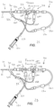
- FIGS. 1A and 1B show an exemplary embodiment of a balloon catheter or apparatus 10 that may include any of the inflation devices or systems described herein, e.g., inflation device 110 (shown in FIGS. 2A-2D ).
- the catheter 10 includes an elongate tubular member or body 12 having a proximal end 14, a distal end 16, and one or more lumens 18 extending between the proximal and distal ends 14, 16, thereby defining a longitudinal axis 20 extending between the proximal and distal ends 14, 16.
- the catheter 10 may be provided as part of a kit or system including one or more additional components, such as external sources of inflation media, e.g., syringes, a guide catheter, and/or one or more guidewires (not shown).
- the catheter 10 may include a pair of overlapping balloons or other expandable members 22 on the distal end 16, e.g., for flaring and/or otherwise expanding a stent previously deployed within a body lumen or carried on the distal end 16, for dilating a stenosis or valve, and/or for performing one or more other procedures within a patient's body (not shown), as described further elsewhere herein.
- the distal end 16 may include one or more markers, e.g., one or more bands of radiopaque material 19, to facilitate positioning the catheter 10 relative to a stent and/or anatomical structures within a patient's body.
- the catheter 10 may include one or more therapeutic and/or diagnostic elements (not shown) on the distal end 16, e.g., within or carried by the balloon(s) 22, as described further below.
- the tubular member 12 may be formed from one or more tubular bodies, e.g., having variable flexibility along its length.
- the distal end 16 may be substantially flexible to facilitate introduction through tortuous anatomy, e.g., terminating in a rounded, tapered, and/or other substantially atraumatic distal tip 17.
- the distal end 16 may be sized and/or shaped for introduction into a body lumen, e.g., having a diameter between about one and seven millimeters (1-7 mm), or less than 1.7 millimeters.
- the proximal end 14 may be substantially flexible, semi-rigid, or rigid, e.g., having sufficient column strength to facilitate advancing the distal end 16 through a patient's vasculature by pushing on the proximal end 14.
- a shaft support wire or other stiffener (not shown) may be provided within the proximal end 14, if desired, e.g., to facilitate pushing the catheter 10 from the proximal end 14.
- the tubular member 12 may be formed from plastic, metal, or composite materials, e.g., a plastic material having a wire, braid, or coil core, which may preventing kinking or buckling of the tubular member 12 during advancement.
- the catheter 10 may include a handle or hub 30 on the proximal end 14, e.g., to facilitate manipulating the catheter 10.
- the handle 30 may include one or more ports 32 communicating with respective lumens 18 within the tubular member 12, as described further below, which may be coupled to corresponding ports on any of the inflation devices herein.
- at least some of the components of the inflation devices may be incorporated into the handle 30, e.g., one or more valves for opening and/or closing fluid paths from a source of inflation media to the lumens 18.
- the handle 30 may be molded, machined, or otherwise formed from plastic, metal, or composite material, e.g., providing an outer casing, which may be contoured or otherwise shaped to ease manipulation.
- the proximal end 14 of the tubular member 12 may be attached to the handle 30, e.g., by bonding, cooperating connectors, interference fit, and the like.
- the handle 30 may include one or more actuators (also not shown), such as one or more slides, dials, buttons, and the like, for actuating or otherwise manipulating the components from the proximal end 14.
- the tubular member 12 includes at least three lumens 18 extending between the proximal and distal ends 14, 16.
- the tubular member 12 may include inflation lumens 18a, 18b that extend from ports 32a, 32b in the handle 30 through the tubular member 12 to openings 34a, 34b and communicate within interiors 23a, 23b of respective balloons 22a, 22b.
- the ports 32a, 32b on the handle 30 may include connectors, e.g., a Luer lock connector (not shown), one or more seals (also not shown), and the like, to facilitate coupling an inflation device to the handle 30.
- the tubular member 12 may include an instrument lumen 18c that extends from port 32c to an opening 34c in the distal tip 17.
- the instrument lumen 18c may have sufficient size to allow a guidewire or other rail or instrument (not shown) to be inserted therethrough, e.g., to facilitate advancing the catheter 10 over the rail, as explained further below.
- an instrument lumen (not shown) may be provided that extends from the handle 30 to the distal end 16.
- the handle 30 may include a port (not shown) and/or one or more seals (also not shown) that prevent fluid, e.g., blood, from flowing proximally out of the port, yet allow one or more instruments to be inserted therethrough and into the instrument lumen 18c.
- fluid e.g., blood
- the tubular member 12 includes a first or inner balloon 22a and a second or outer balloon 22b on the distal end 16, which are expandable independently of one another.
- the balloons 22 may be bonded or otherwise secured to the distal end 16 of the tubular member 12, e.g., by bonding with adhesive, sonic welding, using an annular collar or sleeve, and the like.
- the inner balloon 22a may include a proximal end 24a attached directly to the distal end 16 of the tubular member 12 distal to instrument lumen port 32c and a distal end 26a attached directly to the distal end 16 adjacent the distal tip 17.
- the outer balloon 22b includes a first or distal section 25b that extends at least partially over the inner balloon 22a and a second or proximal section 27b.
- the first section 25b may extend entirely over the inner balloon 22a and a distal end 26b of the outer balloon 22b may be attached over or adjacent to the distal end 26a of the inner balloon 22a, e.g., by bonding, sonic welding, and the like, as described elsewhere herein.
- a proximal end 24b of the outer balloon 22b may be attached to the distal end 16 of the tubular member 12, e.g., proximal or adjacent to the inner balloon proximal end 24a and distal to the instrument lumen port 32c.
- the first section 25b of the outer balloon 22b may overlie but remain separate from the underlying inner balloon 22a.
- the first section 25b may be bonded or otherwise attached to the inner balloon 22a, e.g., continuously or intermittently along the inner balloon 22a.
- the orientation of the outer balloon 22b may be reversed, if desired, e.g., with the second section 25b of the outer balloon 22b extending distally relative to the main section 25a of the inner balloon 22a rather than proximally.
- a substantially spherical or bulbous section may be provided on the outer balloon 22b both proximally and distally to the main section 25a of the inner balloon 22a (not shown).
- the proximal and distal sections may be expanded simultaneously or independently of one another, as desired.
- the inner balloon 22a may be expandable from a contracted condition (not shown) to an enlarged condition (shown in FIGS. 1A and 1B ).
- the outer balloon 22b may also be expandable from a contracted condition (not shown) to an enlarged condition (shown in FIGS. 1A and 1B ).
- One or both balloons 22, e.g., inner balloon 22a may be formed from substantially inelastic material, e.g., PET, nylon, or PEBAX, such that the balloon 22 expands to a predetermined size in its enlarged condition once sufficient fluid is introduced into the interior of the balloon 622.
- one or both balloons 22, e.g., outer balloon 22b may be formed from substantially elastic material, e.g., silicone, polyurethane, or polyethylene, such that the balloon 22 may be expanded to a variety of sizes depending upon the volume and/or pressure of fluid within the interior.
- the inner balloon 22a may be formed from a semi-compliant or substantially non-compliant material, e.g., mid to high durometer PEBAX, nylon, or PET
- the outer balloon 22b may be formed from a substantially complaint or semi-compliant material, e.g., polyethylene, polyurethane, and low to mid durometer PEBAX.
- the balloon material may be formed into a shape including a substantially spherical or other bulbous shape for the proximal section 27b and a substantially uniform, smaller diameter shape for the distal section 25b.
- the balloon material may be blow molded within a mold having the desired shape for the outer balloon 22b when inflated. Because of the compliance of the balloon material, the outer balloon 22b, e.g., the proximal section 27b, may be expanded greater than the relaxed molded shape, yet may substantially maintain that shape unless constrained by external forces.
- the outer balloon 22b may have a substantially uniform wall thickness, e.g., between the proximal and distal sections 27b, 25b. Alternatively, the wall thickness may vary; for example, the proximal section 27b may have a thinner wall thickness than the distal section 25b.
- the outer balloon 22b may include one or more features thereon for enhancing traction, friction, or other engagement with structure contacted by the outer balloon 22b when expanded.
- the outer surface of at least the proximal section 27b may be treated or textured, may include ribs or other protrusions, and the like (not shown) to increase friction or other engagement upon expansion.
- the balloons 22 may operate under different internal pressures and/or may require different pressures sufficient to fully expand the respective balloons 22.
- the inner balloon 22a may require a greater inflation pressure to fully expand than the outer balloon 22b. This may allow the proximal section 27b of the outer balloon 22b to be expanded using a lower inflation pressure to flare and/or shape a flaring portion of a stent without substantial expansion of a main portion of the stent, as described further elsewhere herein and in the applications identified herein.
- the outer balloon 22b may be inflated based upon delivering one or more predetermined volumes of fluid therein, e.g., in multiple stages of expansion, as described further below.
- the proximal section 27b of the outer balloon 122a may be inflated upon delivering a first predetermined volume of fluid therein to flare the stent, e.g., between about 0.25-2 cubic centimeters or between about 0.5-4.2 cubic centimeters.
- Volume-based delivery may be useful for describing the function of the outer balloon 22b because of its relative compliance and/or low pressure requirements.
- the proximal section 27b of the outer balloon 22b may be shaped to expand to a substantially spherical shape in the enlarged condition, e.g., having a diameter between about ten and twenty millimeters (10-20 mm) when expanded using an inflation pressure between about one and five atmospheres (1-5 ATM).
- the proximal section 27b of the outer balloon 22b may have a diameter of about thirteen millimeters (13 mm) at an inflation pressure of about two atmospheres (2 ATM).
- the inner balloon 122b may be shaped to expand to a substantially cylindrical shape in the enlarged condition, e.g., having a diameter between about two and eight millimeters (2-8 mm) when expanded using an inflation pressure between about eight and twenty atmospheres (8-20 ATM).
- a main section 25a of the inner balloon 22a may have a substantially uniform diameter, e.g., having a length between about eight and thirty millimeters (8-30 mm). Beyond the uniform diameter portion, the inner balloon 22a may have a transition portion 27a adjacent the distal tip 17. The transition portion 27a may be tapered, as shown, or may be substantially blunt, i.e., extending inwardly to the distal tip 17 (not shown). As shown, the main portion 25a of the inner balloon 22a may underlie at least a portion of the outer balloon 22b, e.g., the distal section 25b, as shown in FIG. 1B and as disclosed in the applications identified herein.
- the main section 27a of the inner balloon 22a may have a diameter of between about five and six millimeters (5-6 mm) in the enlarged condition and may have a length of at least about seventeen millimeters (17 mm) distally beyond the proximal section 27b of the outer balloon 22b.
- an exemplary embodiment of an inflation device 110 is shown that may be coupled to or integrated into a tubular device, such as the catheter 10 shown in FIGS. 1A and 1B .
- the inflation device 110 includes a pair of valves 112, 114, e.g., three-position stopcocks, coupled together via one or more passages 116, e.g., defined by one or more sections of tubing and the like.
- Each valve 112, 114 may include a valve body or cavity including a plurality of first valve ports and a valve member 112a, 114a movable within the valve body between multiple positions, e.g., for opening and closing a sequence of fluid paths between the valve ports and the catheter 10.
- the valve members 112a, 114a may include one or more passages therethrough that may be aligned with one or more of the valve ports when the valve members 112a, 114a are rotated to one or more positions, as described elsewhere herein.
- the valves 112, 114, and passages 116 may be contained with a rigid housing or manifold (not shown), which may be separate from the catheter 10.
- the manifold may be shaped to be manipulated easily by a user during use, e.g., to actuate the valve members 112a, 114a and/or deliver vacuum or inflation media.
- tubing may be connected between the housing and the handle 30, e.g., between the valves 112, 114 and ports 32a, 32b on the handle 30 for selectively delivering inflation media and/or vacuum to the lumens 18a, 18b and balloons 22a, 22b (not shown, see, e.g., FIG. 1B ).
- the housing may be shaped or otherwise configured such that ports on the housing may be connected directly to the ports 32a, 32b on the handle 30.
- a source of inflation media e.g., syringe 120, pump, and the like, may be connected to the housing, e.g., via tubing 122 such that the source 120 communicates with one of the valves, e.g., valve 112 to selectively deliver inflation media or vacuum to the fluid paths.
- the ports 32a, 32b and the housing of the inflation device 110 may include a pair of ports for connecting tubing between the inflation device 110 and handle 30 before use.
- the ports may include Luer fittings or other connectors to facilitate rapid connection and disconnection of the inflation device 110.
- tubing may be permanently connected to the housing that includes connectors for removably coupling the tubing to the ports 32a, 32b.
- components of the inflation device 110 may be integrally formed within the housing, e.g., by molding, casting, or otherwise creating passages corresponding to the indicated fluid paths.
- the inflation device 110 may be integrated into the handle 30 of the catheter 10 (or other tubular device), e.g., such that the valve members are rotatably mounted within the handle 30 and tubing and/or passages within the handle shell define the fluid paths.
- the handle 30 may include only a single port, e.g., for connecting the syringe 120 or other source of inflation media to the inflation device integrated within the handle 30.
- the inflation device 110 includes an actuator, e.g., a dial, slider, and the like (not shown), coupled to one or both of the valves 112, 114 for directing the valve members 112a, 114a between a plurality of positions, e.g., to open and/or close various valve ports and/or fluid paths, as described further below.
- the actuator may be coupled directly to a first valve member 112a of the valve 112, and the other valve member 114b may be coupled to the first valve member such that actuation of the actuator causes the first valve member to rotate, thereby causing the second valve member to rotate.
- the actuator is rotatable in a first direction to direct the first and second valve members sequentially from a first position to second, third, and fourth positions, and eventually back to the first position.
- the valve ports 112b, 112c, 112d and 114b, 114c, 114d may be offset about ninety degrees (90°) from one another around the valves 112, 114 such that the actuator may be manipulated to rotate the valve members 112a, 114a about ninety degrees between each sequential position, as shown in FIGS. 2A-2D .
- the actuator may be slidable axially or otherwise and may be coupled to one or both valve members 112a, 114a, e.g., by a rack and pinion or other arrangement (not shown), to cause the valve members 112a, 114 to rotate between the first-fourth positions when the actuator is slid axially (after which the actuator may be returned in the opposite direction back to the first position).
- a fluid path is provided from the source of inflation media 120 to both ports 32a, 32b through the valves 112, 114 to the tubing 122 communicating with the syringe 120.
- the first port 32a may communicate with a first valve port 112b of the first valve 112 and the valve member 112b may communicate with a second valve port 112c coupled to the tubing 122.
- the second port 32b may communicate with the second valve 114a through tubing 116a, 116b, fifth valve port 114c and the second valve member 114a may communicate with a fourth valve port 114b coupled to a third valve port 112d of the first valve 112, which may communicate with the second valve port 112c and the tubing 122.
- a source of fluid e.g., saline may be coupled to the tubing 122 and used to flush the lumens 18a, 18b and/or balloons 22a, 22b simultaneously, before using the syringe 120 to pull a vacuum and collapse the balloons 22a, 22b.
- a source of fluid e.g., saline may be coupled to the tubing 122 and used to flush the lumens 18a, 18b and/or balloons 22a, 22b simultaneously, before using the syringe 120 to pull a vacuum and collapse the balloons 22a, 22b.
- the actuator may be manipulated to direct the first and second valve members to a second position, e.g., as shown in FIG. 2B to isolate the third valve port 112d and consequently, close the fluid path through the second valve 114, the tubing 116b, 11a, and the port 32b such that the second lumen 18b is isolated.
- a fluid path between the first lumen 18a and the syringe 120 is open, e.g., from the tubing 122, the second valve port 112c, the valve member 112a, the first valve port 112b, and the port 32a. Consequently, the syringe 120 may be advanced or otherwise manipulated to deliver inflation media from the syringe 120 along the fluid path, as indicated by arrow "I1" through the first 18a lumen to inflate the first balloon 22a.
- the actuator may be rotated or otherwise manipulated further to direct the first and second valve members 112a, 114a to the third position, e.g., as shown in FIG. 2C , to close the fluid path from the first valve member 112a through the first valve port 112b to the port 32a, thereby isolating the first lumen 18a and maintaining the first balloon 18a inflated.
- the actuator may then be rotated further to direct the first and second valve members 112a, 114a to the fourth position, thereby opening a fluid path from the syringe 120 and tubing 122 through the fifth port 114c, the second valve member 114a, and the sixth port 114d, which communicates via tubing 116c, 116a to the port 32b. Consequently, while the first lumen 18a remains isolated (to keep the first balloon 22a inflated), inflation media may be delivered from the syringe 120 along the fluid path, as indicated by arrow "I2" through the second lumen 18b to inflate the second balloon 22b.
- the actuator may be rotated or otherwise manipulated back to the first position shown in FIG. 2A , thereby opening fluid paths from both lumens 18a, 18b to the syringe 120, which may then be actuated to pull a vacuum to collapse both balloons 22a, 22b simultaneously, whereupon the catheter 10 may be removed, e.g., as described further elsewhere herein.
- a flow restrictor 130 may be provided in one of the fluid paths, e.g., in line with tubing 116c such that flow along the fluid path with the actuator in the fourth position is limited in a desired manner.
- the second balloon 22b is an elastic and/or other low-pressure balloon
- a flow restrictor may be located in the fluid path between the first valve port 112b and the port 32a (not shown).
- inflation media may be delivered through tubing 116c (and the flow restrictor 130) into the tubing 116 and port 32b, while, with the valve members 112a, 114a rotated back to the first position ( FIG. 2A ), vacuum may be pulled through tubing 116b and 116a, i.e., bypassing the tubing 116c including the flow restrictor 130. Consequently, the second balloon 22b may be rapidly deflated without flow being limited by the flow restrictor 130.
- This advantage results from the parallel tubing lines 116b and 116c both communicating from the second valve 114 to the tubing 116a and port 32b.
- the syringe 120 may be manipulated to pull vacuum to at least partially collapse the second balloon 22b.
- first balloon 22a is an inelastic and/or other high-pressure balloon
- pressure from the first balloon 22a may travel through the first lumen 18a into the fluid paths of the inflation device 110 and expose the fluid path to the second lumen 18b and second balloon 22b to this pressure, which may otherwise risk over-inflation of the second balloon 22b.
- a pressure relief valve or device may be provided in one or more of the fluid paths to limit pressure within the fluid path to a predetermined maximum pressure.
- a pressure relief valve may be provided in the fluid path communicating with the port 32b, e.g., in line with tubing 116c similar to the flow restrictor 130. Such a pressure relief valve may prevent over-inflation of the second balloon 22b, e.g., as described further elsewhere herein.
- an exemplary method is shown for using the catheter 10 to flare and/or otherwise expand a stent 40 deployed within a patient's body, e.g., including an ostium 90.
- the ostium 90 may be an opening in a wall of a first or main body lumen or trunk 92 that communicates with a second body lumen or branch 94.
- the main body lumen 92 may be the ascending or descending aorta
- the branch body lumen may be a coronary artery, a common carotid artery, or a peripheral artery.
- a stenosis, occlusion, or other lesion 96 may exist at and/or adjacent to the ostium 90, e.g., extending at least partially into the branch 94.
- the lesion 96 may include atherosclerotic plaque or other material that partially or completely occludes blood or other fluid flow between the trunk 92 and the branch 94.
- a guidewire 98 or other rail may be introduced from the trunk 92 through the ostium 90 into the branch 94, e.g., using conventional methods.
- a percutaneous puncture or cut-down may be created at a peripheral location (not shown), such as a femoral artery, carotid artery, or other entry site, and the guidewire 98 may be advanced through the patient's vasculature from the entry site, e.g., alone or with the aid of a guide catheter (not shown).
- a distal end of a guide catheter may be advanced over the guidewire 98 into the trunk 92, e.g., until the distal end is disposed adjacent or proximal to the ostium 90.
- the guide catheter may be used to advance one or more instruments (such as any of the catheters or other devices described herein) over the guidewire 98 and into the trunk 92 and/or branch 94.
- the guidewire 98 may be directed through the occlusion, or other devices (not shown) may be advanced over the guidewire 98 or otherwise in conjunction with the guidewire 98 to create a passage through the lesion 96 for the guidewire 98.
- an angioplasty catheter (not shown) may be advanced through the guide catheter and/or over the guidewire 98 into and through the lesion 96, whereupon a balloon or other element on the catheter may be expanded to at least partially dilate the lesion 96.
- other procedures may also be performed at the lesion 96, e.g., to soften, remove, or otherwise treat plaque or other material forming the lesion 96, before the stent 40 is implanted. After completing any such procedures, any instruments advanced over the guidewire 98 may be removed.
- any delivery catheter and/or conventional procedure may be used.
- a distal end of a delivery catheter (not shown) may be advanced over the guidewire 98 and/or through the guide catheter from the entry site into the trunk 92.
- the distal end of the delivery catheter may be advanced from the guide catheter, through the ostium 90, and into the branch 94.
- the delivery catheter may be positioned such that the stent 40 extends into and through the lesion 96 and/or branch 94.
- the stent 40 may be expanded and/or otherwise deployed from the delivery catheter to place the stent 40 across the lesion 96 and/or within the branch 94. For example, as shown in FIG.
- the stent 40 may be deployed such that a first end 42 of the stent 40 extends at least partially into the ostium 90 and/or the trunk 92, and a second end 44 of the stent 40 is disposed within the branch 94 beyond the lesion 96.
- the stent 40 may have a substantially uniform diameter cross-section once deployed.
- the stent 40 may be expanded to dilate and/or otherwise engage the lesion 96 and/or branch 94.
- the stent 40 may be partially expanded using the delivery catheter, allowing the stent 40 to be further expanded by the apparatus 10, as described below.
- the distal end 16 of the catheter 10 (with the balloons 22 in their contracted conditions) may be introduced into the trunk 92 to flare and/or otherwise expand the stent 40.
- the actuator may be manipulated to direct the valve members 112a, 114a to the first position shown in FIG. 2A , whereupon a vacuum may be applied via the syringe 120 to simultaneously collapse and/or otherwise prepare the balloons 22 for introduction.
- the delivery catheter may be removed, and the distal end 16 of the catheter 10 may be advanced over the same guidewire 98 into the trunk 92.
- a proximal end (not shown) of the guidewire 98 may be backloaded into the opening 34c through the instrument lumen 18c and out the port 32c.
- the distal end 16 may then be advanced over the guidewire 98 into the patient's body over the guidewire 98.
- the distal end 16 may be advanced through the stent 40 and ostium 90 at least partially into the branch 94.
- the distal end 16 may be positioned such that the inner balloon 22a is positioned within and/or beyond the stent 40, e.g., beyond the first end 42, and the proximal section 27b of the outer balloon 22b is positioned adjacent the ostium 90, e.g., within and/or proximal to the first end 42 of the stent.
- the distal end 16 may be monitored using fluoroscopy or other external imaging, e.g., to observe and monitor markers 19 (not shown, see FIG. 1B ) on the distal end 16.
- markers 19a and 19b may be located on the distal end 16 to identify the ends of the substantially uniform main section 25a of the inner balloon 22a
- proximal marker 19c may be located on the distal end 16 to identify the proximal end 24b and/or proximal section 27b of the outer balloon 22b.
- the inner balloon 22a may be aligned with the distal end 44 and/or portion of the stent 40 within the branch 94 beyond the ostium 90 and the proximal section 27b of the outer balloon 22b may be aligned with the first end 42 of the stent 40 and/or the ostium 90, as desired.
- the inflation device 110 may be operated to inflate the balloons 22 in a desired manner to flare and/or otherwise further expand the stent 40.
- the actuator may be directed to the second position shown in FIG. 2B , whereupon the inner balloon 22a may be expanded to engage the stent 40 and/or wall of the branch 94, e.g., expanded to engage both the second end 44 of the stent 40 and the wall of the branch 94 beyond the stent 40 to prevent substantial axial migration of the stent 40.
- the actuator may be directed to the third position to isolate the inner balloon 22a and keep the balloon 22a inflated, as shown in FIG. 2C .
- the actuator may then be directed to the fourth position, as shown in FIG. 2D and the proximal section 27b of the outer balloon 22b may be expanded to flare the stent 40, e.g., as shown in FIG. 3E .
- the proximal section 27b is expanded, the first end 42 of the stent 40 is expanded, e.g., into a flared configuration, which may conform to the shape of the proximal section 27b and/or the ostium 90.
- the stent 40 and distal end 16 may remain substantially stationary during this inflation and flaring.
- the inner balloon 22a may be inflated further, if desired, e.g., to expand the stent 40 and further dilate the lesion 96.
- the actuator may be directed to the first position shown in FIG. 2A , and the balloons 22 may be deflated or otherwise collapsed, e.g., simultaneously.
- the catheter 10 may then be withdrawn from the branch 94 and trunk 92, and from the patient's body, e.g., into the guide catheter (not shown).
- the guide catheter and/or guidewire 98 may then be removed from the patient's body, leaving the stent 40 in place, as shown in FIG. 2F.
- inflation sequences may be used with the inflation devices herein, e.g., to initially deliver and deploy a stent and then flare the stent, e.g., within an ostium 90.
- the catheter 10 may be used to expand a stent previously placed within a substantially straight or other non-bifurcated body lumen, such as within a carotid, iliac, renal, coronary artery, or other blood vessel.
- a stent or other prosthesis such as those disclosed in the applications identified herein, may be provided on the distal end 16 of the catheter 10, e.g., over the balloons 22, rather than on a separate delivery catheter, if desired.
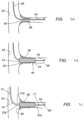
- FIGS. 4A-4D another example of an inflation device 210 is shown that includes a flow control manifold 212 communicating with ports 32a, 32b on a handle 30 of a catheter 10 and a syringe or other source of inflation media 120, e.g., via tubing 216, generally similar to the previous embodiments.
- An actuator may be coupled to one or more valve members of the manifold 212 (not shown), e.g., for opening and closing ports 212a, 212b, 212c of the manifold 212. in a desired manner to facilitate applying vacuum and/or delivering inflation media to the ports 32a, 32b to collapse and/or expand balloons (not shown) on the catheter 10.
- the manifold 212 may include two valves therein with valve ports arranged to provide one or more fluid paths, similar to other embodiments herein.
- both ports 32a, 32b communicate with the syringe 120 via tubing 216 and open ports 212a, 212b, 212c of the manifold 212. Consequently, the syringe 120 may be manipulated to draw vacuum through the inflation device 210, as indicated by arrows "V" through both fluid paths including tubing 216a, 216b/216c to collapse both balloons simultaneously.
- the actuator has been directed to close the second manifold port 212b communicating via tubing 216b, 216c to the second port 32b while the first manifold port 212a remains open and in communication the third manifold port 212c. Consequently, the syringe 120 may be manipulated to deliver inflation media though the manifold 212 and tubing 216a to the first port 32a for inflating the first balloon while the second balloon remains collapsed (not shown, see, e.g., FIG. 3D ).
- the actuator has been directed to open the second manifold port 212b and close the first manifold port 212a, thereby opening a fluid path via tubing 216b, 16c to the second port 32b. Consequently, the syringe 120 may be manipulated to deliver inflation media though the manifold 212 and tubing 216b, 216c to the second port 32b for inflating the second balloon while the first balloon remains inflated (not shown, see, e.g., FIG. 3E ).
- a pressure relief valve 230 is provided in line with the tubing 216b, 216c to limit the pressure of inflation media delivered to the second port 32b and, consequently, the second balloon 22b (shown in FIG. 1B ).
- the second balloon 22b may be an elastic and/or low-pressure balloon and so, it may be desirable to limit pressure delivered into the balloon 22b to avoid over-inflation and/or rupture.
- the pressure relief valve 230 includes a substantially rigid casing or housing 232 including ends 232a, 232b with ports for communicating with the tubing 216b, 216c and a sidewall 234 including one or more holes 236.
- the valve 230 also includes a flexible piece of tubing, bladder, or other material 240 mounted around an outer surface of the casing 232, e.g., including ends 240a, 24b attached to the ends 232a, 232b of the casing 232 to provide an enclosed and/or sealed interior region communicating with the hole(s) 236.
- the hole(s) 236 permit inflation media entering the casing 232 to escape therethrough to expand the bladder 240 when a predetermined pressure is exceeded.
- excess pressure may cause the bladder 240 to expand thereby storing excess inflation media within bladder 240 and preventing the excess pressure from passing through to the second port 32b and the interior of the second balloon 22b. If the pressure of the inflation media falls below the predetermined pressure, the bladder 240 may be biased to collapse towards the casing 232, thereby directing the excess inflation media out of the casing 232, e.g., along tubing 216c into the second port 32b.
- the pressure relief valve 230 may facilitate maintaining the second balloon 22b at a desired inflation pressure when inflated even if the pressure from the syringe 120 varies.
- the bladder 240 may be formed from semi-compliant or compliant material, e.g., having desired wall thickness, durometer, length, and/or other mechanical properties, to set the predetermined pressure at a target maximum pressure.
- the number and/or size of holes 236 may be selected to adjust the predetermined pressure.
- the pressure relief valve 230 may prevent excessive pressure from being applied to the second port 32b and, consequently, the second balloon 22b.
- the pressure relief valve 230 may store a volume of inflation media and/or store a target pressure within the bladder 240. For example, if the stored pressure/volume of fluid from position two is greater than or equal to what is required to inflate the low pressure balloon, the manifold 212 may simply be directed from position three to position four, and the balloon 22b attached to the low pressure inflation lumen may automatically inflate to the correct volume/pressure.
- an inflation device 310 that generally includes a manifold 212, source of inflation media 120, and a pressure relief valve 330 communicating via tubing 216, e.g., similar to previous embodiments.
- the pressure relief valve 330 includes a rigid casing or housing 332 with a balloon 340 mounted therein.
- the balloon 340 may include ends 340a, 340b attached to or otherwise sealingly connected to the tubing 216b, 216c such that inflation media from the syringe 120 passing through the tubing 216b, 216c also passes through the interior of the balloon 340.
- the balloon 340 may be formed from compliant or non-compliant material, e.g., having a nominal diameter substantially the same as the inner diameter of the casing 332.
- the pressure relief valve 330 may prevent excessive pressure from being applied to the low pressure inflation lumen/balloon, as all of the pressure/volume stored from position two may be used to inflate the balloon 340 inside the casing 332.
- the inflation device 330 may be used to apply a target pressure and/or volume desired for the low pressure inflation lumen.
- an inflation device 410 generally includes a manifold 212, source of inflation media 120, and a pressure relief device 430 communicating via tubing 216, e.g., similar to previous embodiments.
- the pressure relief device 430 includes a mechanism for restricting flow through tubing 216b, 216c, e.g., when the manifold 212 is directed from position three ( FIG. 6C ) and position four ( FIG. 6D ).
- the pressure relief device 430 may include an external clamp, e.g., positioned around a region of the tubing 216b, 216c, with an integrated pressure sensor and/or timer, that automatically stops flow when a predetermined pressure limit is exceeded and restores flow when the pressure drops below the predetermined pressure, thereby preventing undesired over-inflation of the balloon attached to the low pressure inflation lumen.
- an external clamp e.g., positioned around a region of the tubing 216b, 216c, with an integrated pressure sensor and/or timer, that automatically stops flow when a predetermined pressure limit is exceeded and restores flow when the pressure drops below the predetermined pressure, thereby preventing undesired over-inflation of the balloon attached to the low pressure inflation lumen.
- the pressure relief device 430 may include a manual flow arrest mechanism that may be activated manually by a user at any time.
- the pressure sensor/timer and associated clamping mechanism may be include known mechanical components (e.g., spring/diaphragm mechanisms) or electronically controlled components.
- the pressure relief device 430 may include an in-line mechanical flow restrictor, e.g., similar to the flow restrictor described elsewhere herein that may cause the balloon attached to the low pressure inflation lumen to slowly inflate, e.g., at a predetermined maximum rate, as the stored pressure pushes fluid through the flow restrictor.
- the pressure relief device 430 may include a one-way valve, optionally, including a flow restrictor or a manual device, e.g., a stopcock or other actuator, that may be manipulated to limit flow in a desired manner.
- the syringe 120 may be used to deliver inflation media at a relatively high pressure, e.g., to inflate a inelastic and/or high pressure balloon, such as those described elsewhere herein.
- the pressure relief device 430 may prevent an residual pressure from being transmitted quickly to the second balloon, e.g., an elastic and/or low pressure balloon.
- the flow restrictor may slow fluid flow, thereby minimizing the risk of the second balloon being over-inflated and/or rupturing, while allowing the residual back pressure to continue to inflate the second balloon, e.g., until the pressure is released and/or vacuum is delivered to the inflation device 410.
Landscapes
- Health & Medical Sciences (AREA)
- Heart & Thoracic Surgery (AREA)
- Life Sciences & Earth Sciences (AREA)
- Engineering & Computer Science (AREA)
- Biomedical Technology (AREA)
- Public Health (AREA)
- General Health & Medical Sciences (AREA)
- Veterinary Medicine (AREA)
- Animal Behavior & Ethology (AREA)
- Anesthesiology (AREA)
- Hematology (AREA)
- Child & Adolescent Psychology (AREA)
- Pulmonology (AREA)
- Biophysics (AREA)
- Vascular Medicine (AREA)
- Cardiology (AREA)
- Oral & Maxillofacial Surgery (AREA)
- Transplantation (AREA)
- Media Introduction/Drainage Providing Device (AREA)
Claims (15)
- Dispositif de gonflage (110, 210, 310, 410) pour gonfler et dégonfler sélectivement des premier et second ballonnets (22a, 22b) sur un élément tubulaire (12) via des première et seconde lumières (18a, 18b) lorsque le dispositif de gonflage est couplé à l'élément tubulaire (12), le dispositif de gonflage comprenant :une première valve (112) comprenant une pluralité de premiers orifices de valve (112b, 112c, 112d) et un premier élément de valve (112a) mobile entre plusieurs positions pour ouvrir et fermer des chemins de fluide entre les premiers orifices de valve ;une seconde valve (114) comprenant une pluralité de seconds orifices de valve (114b, 114c, 114d) et un second élément de valve (114a) mobile entre plusieurs positions pour ouvrir et fermer des chemins de fluide entre les seconds orifices de valve ; etune source de milieu de gonflage (120) couplée à l'un des premiers orifices de valve ;le dispositif de gonflage étant caractérisé par :
un actionneur couplé aux premier et second éléments de valve pour diriger les premier et second éléments de valve entre des première, deuxième, troisième et quatrième positions, dans lequel :i) avec les premier et second éléments de valve dans la première position, le dispositif de gonflage fournit un chemin de fluide allant de la source de milieu de gonflage jusqu'aux première et seconde lumières, le dispositif de gonflage étant ainsi configuré de sorte que la source de milieu de gonflage peut être actionnée pour aspirer un vide le long du chemin de fluide pour plier les premier et second ballonnets simultanément ;ii) avec les premier et second éléments de valve dans la deuxième position, le dispositif de gonflage isole la seconde lumière tout en ouvrant un chemin de fluide entre la première lumière et la source de milieu de gonflage de sorte que le milieu de gonflage distribué à partir de la source de milieu de gonflage par la première lumière, gonfle le premier ballonnet ;iii) avec les premier et second éléments de valve dans la troisième position, le dispositif de gonflage isole la première lumière pour maintenir le premier ballonnet gonflé ; etiv) avec les premier et second éléments de valve dans la quatrième position, le dispositif de gonflage ouvre un chemin de fluide allant de la source de milieu de gonflage à la seconde lumière, tout en isolant la première lumière de sorte que le milieu de gonflage distribué à partir de la source de milieu de gonflage par la seconde lumière, gonfle le second ballonnet. - Dispositif de gonflage selon la revendication 1, dans lequel l'actionneur est directement couplé au premier élément de valve et dans lequel le second élément de valve est couplé au premier élément de valve de sorte que l'actionnement de l'actionneur provoque la rotation du premier élément de valve, provoquant ainsi la rotation du second élément de valve.
- Dispositif de gonflage selon la revendication 1, dans lequel les premier et second éléments de valve sont couplés ensemble par des engrenages (132) de sorte que la rotation du premier élément de valve dans le sens des aiguilles d'une montre provoque la rotation du second élément de valve dans le sens inverse des aiguilles d'une montre.
- Dispositif de gonflage selon la revendication 1, dans lequel l'actionneur peut tourner dans une première direction pour diriger les premier et second éléments de valve de manière séquentielle entre les première, deuxième, troisième et quatrième positions.
- Dispositif de gonflage selon la revendication 4, dans lequel la rotation supplémentaire de l'actionneur dans la première direction à partir de la quatrième position ramène les premier et second éléments de valve à la première position.
- Dispositif de gonflage selon la revendication 1, comprenant en outre un limiteur d'écoulement (130) dans le chemin de fluide lorsque les premier et second éléments de valve sont dans la quatrième position pour limiter un débit de gonflage du second ballonnet.
- Dispositif de gonflage selon la revendication 1, comprenant en outre un limiteur de pression (230, 330, 430) dans le chemin de fluide communiquant de la source de milieu de gonflage à la seconde lumière, le limiteur de pression étant configuré pour libérer la pression en excès lorsque les premier et second éléments de valve sont dirigés dans la quatrième position.
- Dispositif de gonflage selon la revendication 7, dans lequel le limiteur de pression comprend :une enveloppe rigide (232) comprenant un intérieur communiquant avec le chemin de fluide et un ou plusieurs trous (236) dans sa paroi latérale (234) ; etun élément flexible (240) au moins partiellement autour de l'enveloppe comprenant un intérieur communiquant avec l'intérieur de l'enveloppe via les un ou plusieurs trous,dans lequel l'élément flexible est configuré pour se dilater à l'opposé de l'enveloppe lorsque la pression du milieu de gonflage dans l'intérieur de l'enveloppe dépasse une pression prédéterminée pour limiter l'un ou les deux parmi l'écoulement et la pression du milieu de gonflage communiquant avec le second ballonnet.
- Dispositif de gonflage selon la revendication 7, dans lequel le limiteur de pression comprend :une enveloppe rigide (332) comprenant un intérieur ; etun élément flexible (340) dans l'intérieur de l'enveloppe et comprenant des extrémités (340a, 340b) communiquant avec le chemin de fluide de sorte que le milieu de gonflage se déplaçant le long du chemin de fluide passe à travers un intérieur du ballonnet,dans lequel l'élément flexible est configuré pour se dilater dans l'intérieur de l'enveloppe lorsque la pression du milieu de gonflage dans l'élément flexible dépasse une pression prédéterminée pour limiter un ou les deux parmi l'écoulement et la pression du milieu de gonflage communiquant avec le second ballonnet.
- Dispositif de gonflage selon la revendication 8 ou 9, dans lequel l'élément flexible est sollicité pour se plier afin de maintenir une pression cible dans le chemin de fluide jusqu'au second ballonnet.
- Appareil pour réaliser une procédure médicale, comprenant :a) un cathéter (10) comprenant :i) un élément tubulaire allongé (12) comprenant une extrémité proximale (14) et une extrémité distale (16) dimensionnées pour l'introduction dans le corps d'un patient ;ii) un premier ballonnet (22a) sur l'extrémité distale comprenant un premier intérieur communiquant avec une première lumière (18a) dans l'élément tubulaire s'étendant vers un premier orifice de lumière sur l'extrémité proximale ; etiii) un second ballonnet (22b) sur l'extrémité distale comprenant un second intérieur communiquant avec une seconde lumière (18b) dans l'élément tubulaire s'étendant vers un second orifice de lumière sur l'extrémité proximale ; etb) un dispositif de gonflage selon l'une quelconque des revendications précédentes.
- Appareil selon la revendication 11, comprenant en outre un limiteur de pression (430) dans le chemin de fluide communiquant de la source de milieu de gonflage jusqu'à la seconde lumière, le limiteur de pression étant configuré pour libérer la pression en excès lorsque les premier et second éléments de valve sont dirigés vers la quatrième position,
dans lequel le limiteur de pression comprend :
un mécanisme de serrage pour fermer le tube dans le chemin de fluide afin d'interrompre l'écoulement du milieu de gonflage le long du chemin de fluide. - Appareil selon la revendication 12, le limiteur de pression comprenant un capteur de pression qui active automatiquement le mécanisme de serrage pour arrêter l'écoulement lorsqu'une limite de pression prédéterminée est dépassée et rétablir l'écoulement lorsque la pression chute au-dessous de la pression prédéterminée, empêchant ainsi le sur-gonflage indésiré du second ballonnet.
- Appareil selon la revendication 11, dans lequel le dispositif de gonflage comprend un boîtier portant la première valve, la seconde valve et l'actionneur, le boîtier comprenant un orifice comprenant un connecteur pour coupler, de manière détachable, la source de milieu de gonflage au boîtier, de sorte que la source de milieu de gonflage communique avec le deuxième orifice de valve, et facultativement, dans lequel le boîtier comprend en outre des orifices comprenant des connecteurs pour coupler, de manière détachable, le tube entre le boîtier et les premier et second orifices de lumière de sorte que le premier orifice de valve communique avec le premier orifice de lumière et le cinquième orifice de valve communique avec le second orifice de lumière.
- Appareil selon la revendication 11, dans lequel l'élément tubulaire comprend une poignée ou raccord sur l'extrémité proximale et dans lequel les première et seconde valves sont portées dans la poignée ou raccord, et facultativement, dans lequel l'actionneur comprend l'un parmi un cadran et un curseur monté sur la poignée ou le raccord.
Applications Claiming Priority (2)
| Application Number | Priority Date | Filing Date | Title |
|---|---|---|---|
| US201862740883P | 2018-10-03 | 2018-10-03 | |
| PCT/US2019/054591 WO2020072837A1 (fr) | 2018-10-03 | 2019-10-03 | Dispositifs et systèmes de gonflage de cathéters à ballonnets, et méthodes d'utilisation |
Publications (4)
| Publication Number | Publication Date |
|---|---|
| EP3860701A1 EP3860701A1 (fr) | 2021-08-11 |
| EP3860701A4 EP3860701A4 (fr) | 2022-06-22 |
| EP3860701B1 true EP3860701B1 (fr) | 2025-07-09 |
| EP3860701B8 EP3860701B8 (fr) | 2025-08-13 |
Family
ID=70051199
Family Applications (1)
| Application Number | Title | Priority Date | Filing Date |
|---|---|---|---|
| EP19868996.0A Active EP3860701B8 (fr) | 2018-10-03 | 2019-10-03 | Dispositifs et systèmes de gonflage de cathéters à ballonnets |
Country Status (5)
| Country | Link |
|---|---|
| US (3) | US11850386B2 (fr) |
| EP (1) | EP3860701B8 (fr) |
| JP (1) | JP2022508626A (fr) |
| CN (1) | CN113301942A (fr) |
| WO (1) | WO2020072837A1 (fr) |
Families Citing this family (9)
| Publication number | Priority date | Publication date | Assignee | Title |
|---|---|---|---|---|
| EP4049625B1 (fr) | 2011-12-09 | 2025-01-08 | Edwards Lifesciences Corporation | Valvule cardiaque prothétique ayant des supports de commissures améliorés |
| USD952840S1 (en) * | 2019-09-12 | 2022-05-24 | Keymed (Medical & Industrial Equipment) Ltd. | Medical instrument |
| US11666744B2 (en) * | 2020-05-29 | 2023-06-06 | Basis Medical, Llc | Multi-lumen manifold and method of operating a multi-lumen manifold |
| CA3225731A1 (fr) * | 2021-07-12 | 2023-01-19 | Jason L. Quill | Systemes et procedes d'alignement commissural previsible d'une valvule cardiaque de remplacement |
| WO2023014792A1 (fr) * | 2021-08-04 | 2023-02-09 | Boston Scientific Scimed, Inc. | Dispositif, système et procédé de mise en place d'endoprothèse ostiale |
| CN113694351B (zh) * | 2021-09-18 | 2023-06-20 | 温州市人民医院 | 一种用于在术中修复漏气的双球囊导管的加压装置 |
| CN114225186B (zh) * | 2021-12-15 | 2022-08-16 | 深圳市远为医疗技术有限公司 | 一种可调控球囊导管 |
| CN116570822A (zh) * | 2022-02-01 | 2023-08-11 | 艾柯医疗器械(北京)股份有限公司 | 多腔球囊导引导管装置和使用方法 |
| CN115531714A (zh) * | 2022-10-24 | 2022-12-30 | 深圳市爱博医疗机器人有限公司 | 一种流体控制机构 |
Family Cites Families (33)
| Publication number | Priority date | Publication date | Assignee | Title |
|---|---|---|---|---|
| US4178938A (en) * | 1977-06-24 | 1979-12-18 | Au Anthony S | Pressure control systems |
| FR2517017B1 (fr) * | 1981-11-20 | 1986-09-19 | Caoutchouc Manuf Plastique | |
| US4654027A (en) * | 1985-10-30 | 1987-03-31 | Dragan William B | Vascular dilating device |
| US5813842A (en) * | 1989-09-22 | 1998-09-29 | Tamari; Yehuda | Pressure sensitive valves for extracorporeal pumping-3 |
| US5336051A (en) * | 1989-09-22 | 1994-08-09 | Yehuda Tamari | Inline non-invasive pressure monitoring system for pumps |
| US5725535A (en) * | 1996-09-20 | 1998-03-10 | Hegde; Anant V. | Multiple balloon stent delivery catheter and method |
| US6083205A (en) * | 1998-01-28 | 2000-07-04 | Intella Interventional Systems | Multiple valve single port manifold |
| US6241706B1 (en) * | 1999-07-16 | 2001-06-05 | Datascope Investment Corporation | Fast response intra-aortic balloon pump |
| US6520977B2 (en) * | 1999-12-06 | 2003-02-18 | Hadi Piraka | Uterine balloon apparatus and method |
| US6419657B1 (en) * | 2000-08-22 | 2002-07-16 | Advanced Cardiovascular Systems, Inc. | Flow regulator valve to optimize stent deployment and method of using the same |
| US20030078538A1 (en) * | 2000-12-28 | 2003-04-24 | Neale Paul V. | Inflation device for dual balloon catheter |
| US6958051B2 (en) * | 2001-10-29 | 2005-10-25 | Scimed Life Systems, Inc. | Dual balloon valve control with pressure indicator |
| US9034025B2 (en) | 2005-05-23 | 2015-05-19 | Ostial Corporation | Balloon catheters and methods for use |
| US7862601B2 (en) | 2005-05-23 | 2011-01-04 | Incept Llc | Apparatus and methods for delivering a stent into an ostium |
| EP1933777B1 (fr) | 2005-08-22 | 2017-06-14 | Incept, LLC | Stents evases et appareil pour leur utilisation |
| JP2007130082A (ja) * | 2005-11-08 | 2007-05-31 | Fujinon Corp | 内視鏡または挿入補助具 |
| US7766893B2 (en) * | 2005-12-07 | 2010-08-03 | Boston Scientific Scimed, Inc. | Tapered multi-chamber balloon |
| US8486134B2 (en) * | 2007-08-01 | 2013-07-16 | Boston Scientific Scimed, Inc. | Bifurcation treatment system and methods |
| CN201772106U (zh) * | 2010-02-01 | 2011-03-23 | 高敏 | 多回路同步控制阀 |
| US20120101515A1 (en) * | 2010-10-21 | 2012-04-26 | Abbott Cardiovascular Systems Inc. | Pressure induced color change for balloon catheter chassis |
| EP2780068B1 (fr) * | 2011-11-16 | 2021-06-23 | Convatec Technologies, Inc. | Appareil pour prévenir un surgonflement du ballonnet de retenue dans des cathéters médicaux et des dispositifs de voies aériennes |
| CN202951128U (zh) * | 2012-05-22 | 2013-05-29 | 娄锋 | 新型麻醉专用四通阀 |
| KR20150096788A (ko) * | 2012-12-21 | 2015-08-25 | 마이크로닉스 인코포레이티드. | 마이크로 유체공학 용도를 위한 저탄성 막 |
| US9468737B2 (en) * | 2013-07-12 | 2016-10-18 | Cook Medical Technologies Llc | Perfusion regulation system |
| US9855409B2 (en) * | 2014-03-25 | 2018-01-02 | Philip Avevor | Device for independently inflating, deflating, supplying contrast media to and monitoring up to two balloon catheters for angioplasty |
| US9144668B1 (en) * | 2014-03-25 | 2015-09-29 | Philip Avevor | Expandable device for independently inflating, deflating, supplying contrast media to and monitoring up to two balloon catheters for angioplasty |
| FR3042573B1 (fr) * | 2015-10-19 | 2018-03-30 | Sotra Seperef | Dispositif d’obturation pour regler la pression ou le debit d’ecoulement dans un tube, et procede de fabrication d’un tube |
| EP3368136B1 (fr) * | 2015-10-29 | 2025-08-06 | ConvaTec Technologies Inc. | Système de soupape pour dispositifs gonflables |
| CN105498071B (zh) * | 2015-12-31 | 2019-06-07 | 南京双威生物医学科技有限公司 | 一种前列腺扩裂封闭注水系统 |
| EP3405709A4 (fr) * | 2016-01-18 | 2019-08-14 | Ham-Let (Israel-Canada) Ltd. | Soupape de commutation de flux avec mécanisme de synchronisation |
| CN205729954U (zh) * | 2016-04-25 | 2016-11-30 | 中国人民解放军第四军医大学 | 一种能够缓冲压力的深静脉置管 |
| CN206530813U (zh) * | 2016-12-29 | 2017-09-29 | 北京金风科创风电设备有限公司 | 水囊式稳压罐 |
| CN207880120U (zh) * | 2017-12-11 | 2018-09-18 | 天津开发区天水华源机电设备技术有限公司 | 一种转换球阀 |
-
2019
- 2019-10-03 WO PCT/US2019/054591 patent/WO2020072837A1/fr not_active Ceased
- 2019-10-03 EP EP19868996.0A patent/EP3860701B8/fr active Active
- 2019-10-03 US US16/592,739 patent/US11850386B2/en active Active
- 2019-10-03 JP JP2021543989A patent/JP2022508626A/ja active Pending
- 2019-10-03 CN CN201980079434.6A patent/CN113301942A/zh active Pending
-
2023
- 2023-12-26 US US18/396,573 patent/US20240277979A1/en not_active Abandoned
-
2025
- 2025-07-08 US US19/263,398 patent/US20250332391A1/en active Pending
Also Published As
| Publication number | Publication date |
|---|---|
| EP3860701A1 (fr) | 2021-08-11 |
| WO2020072837A1 (fr) | 2020-04-09 |
| US20250332391A1 (en) | 2025-10-30 |
| EP3860701A4 (fr) | 2022-06-22 |
| JP2022508626A (ja) | 2022-01-19 |
| EP3860701B8 (fr) | 2025-08-13 |
| US11850386B2 (en) | 2023-12-26 |
| US20240277979A1 (en) | 2024-08-22 |
| US20200108234A1 (en) | 2020-04-09 |
| CN113301942A (zh) | 2021-08-24 |
Similar Documents
| Publication | Publication Date | Title |
|---|---|---|
| EP3860701B1 (fr) | Dispositifs et systèmes de gonflage de cathéters à ballonnets | |
| US11980556B2 (en) | Balloon catheters and methods for use | |
| US11510797B2 (en) | Balloon catheters and methods for use | |
| US5788708A (en) | Multiple balloon stent delivery catheter and method | |
| EP1901797B1 (fr) | Appareil pour introduire un stent dans un ostium | |
| US5782855A (en) | Stent delivery system | |
| CN103476351B (zh) | 用于处理体腔内阻塞的装置和方法 | |
| US7131986B2 (en) | Catheter having exchangeable balloon | |
| CN109381783B (zh) | 药物涂层球囊导管 | |
| KR102588511B1 (ko) | 환자 신체로의 의료 기기의 제어된 이송을 위한 시스템 및 방법 | |
| JPH09192232A (ja) | ステント挿入用バルーンカテーテル | |
| US20200146858A1 (en) | Dual balloon catheters and methods for use | |
| WO2017120606A1 (fr) | Ballonnet dans un cathéter de guidage |
Legal Events
| Date | Code | Title | Description |
|---|---|---|---|
| STAA | Information on the status of an ep patent application or granted ep patent |
Free format text: STATUS: THE INTERNATIONAL PUBLICATION HAS BEEN MADE |
|
| PUAI | Public reference made under article 153(3) epc to a published international application that has entered the european phase |
Free format text: ORIGINAL CODE: 0009012 |
|
| STAA | Information on the status of an ep patent application or granted ep patent |
Free format text: STATUS: REQUEST FOR EXAMINATION WAS MADE |
|
| 17P | Request for examination filed |
Effective date: 20210412 |
|
| AK | Designated contracting states |
Kind code of ref document: A1 Designated state(s): AL AT BE BG CH CY CZ DE DK EE ES FI FR GB GR HR HU IE IS IT LI LT LU LV MC MK MT NL NO PL PT RO RS SE SI SK SM TR |
|
| DAV | Request for validation of the european patent (deleted) | ||
| DAX | Request for extension of the european patent (deleted) | ||
| A4 | Supplementary search report drawn up and despatched |
Effective date: 20220525 |
|
| RIC1 | Information provided on ipc code assigned before grant |
Ipc: A61F 2/82 20130101ALN20220519BHEP Ipc: A61M 25/01 20060101ALN20220519BHEP Ipc: A61F 2/954 20130101ALI20220519BHEP Ipc: A61F 2/958 20130101ALI20220519BHEP Ipc: A61M 25/10 20130101AFI20220519BHEP |
|
| GRAP | Despatch of communication of intention to grant a patent |
Free format text: ORIGINAL CODE: EPIDOSNIGR1 |
|
| STAA | Information on the status of an ep patent application or granted ep patent |
Free format text: STATUS: GRANT OF PATENT IS INTENDED |
|
| RIC1 | Information provided on ipc code assigned before grant |
Ipc: A61F 2/82 20130101ALN20241112BHEP Ipc: A61M 25/01 20060101ALN20241112BHEP Ipc: A61F 2/954 20130101ALI20241112BHEP Ipc: A61F 2/958 20130101ALI20241112BHEP Ipc: A61M 25/10 20130101AFI20241112BHEP |
|
| INTG | Intention to grant announced |
Effective date: 20241120 |
|
| GRAS | Grant fee paid |
Free format text: ORIGINAL CODE: EPIDOSNIGR3 |
|
| GRAA | (expected) grant |
Free format text: ORIGINAL CODE: 0009210 |
|
| STAA | Information on the status of an ep patent application or granted ep patent |
Free format text: STATUS: THE PATENT HAS BEEN GRANTED |
|
| AK | Designated contracting states |
Kind code of ref document: B1 Designated state(s): AL AT BE BG CH CY CZ DE DK EE ES FI FR GB GR HR HU IE IS IT LI LT LU LV MC MK MT NL NO PL PT RO RS SE SI SK SM TR |
|
| REG | Reference to a national code |
Ref country code: GB Ref legal event code: FG4D |
|
| REG | Reference to a national code |
Ref country code: CH Ref legal event code: EP |
|
| REG | Reference to a national code |
Ref country code: DE Ref legal event code: R081 Ref document number: 602019072429 Country of ref document: DE Owner name: SANATI, ARCHIMEDES, CAMPBELL, US Free format text: FORMER OWNERS: CO, FRED, H., SANTA CLARA, CA, US; OSTIAL CORPORATION, CAMPBELL, CA, US; SANATI, ARCHIMEDES, CAMPBELL, CA, US; WOLENBERG, JAKE, SANTA CLARA, CA, US; YANG, YI, SAN FRANCISCO, CA, US Ref country code: DE Ref legal event code: R081 Ref document number: 602019072429 Country of ref document: DE Owner name: VERGE MEDICAL, INC., CAMPBELL, US Free format text: FORMER OWNERS: CO, FRED, H., SANTA CLARA, CA, US; OSTIAL CORPORATION, CAMPBELL, CA, US; SANATI, ARCHIMEDES, CAMPBELL, CA, US; WOLENBERG, JAKE, SANTA CLARA, CA, US; YANG, YI, SAN FRANCISCO, CA, US |
|
| REG | Reference to a national code |
Ref country code: IE Ref legal event code: FG4D |
|
| REG | Reference to a national code |
Ref country code: CH Ref legal event code: PK Free format text: BERICHTIGUNG B8 Ref country code: DE Ref legal event code: R096 Ref document number: 602019072429 Country of ref document: DE |
|
| RAP2 | Party data changed (patent owner data changed or rights of a patent transferred) |
Owner name: VERGE MEDICAL, INC. Owner name: SANATI, ARCHIMEDES |
|
| REG | Reference to a national code |
Ref country code: NL Ref legal event code: MP Effective date: 20250709 |
|
| PG25 | Lapsed in a contracting state [announced via postgrant information from national office to epo] |
Ref country code: PT Free format text: LAPSE BECAUSE OF FAILURE TO SUBMIT A TRANSLATION OF THE DESCRIPTION OR TO PAY THE FEE WITHIN THE PRESCRIBED TIME-LIMIT Effective date: 20251110 |
|
| PG25 | Lapsed in a contracting state [announced via postgrant information from national office to epo] |
Ref country code: NL Free format text: LAPSE BECAUSE OF FAILURE TO SUBMIT A TRANSLATION OF THE DESCRIPTION OR TO PAY THE FEE WITHIN THE PRESCRIBED TIME-LIMIT Effective date: 20250709 |
|
| REG | Reference to a national code |
Ref country code: AT Ref legal event code: MK05 Ref document number: 1811299 Country of ref document: AT Kind code of ref document: T Effective date: 20250709 |
|
| PG25 | Lapsed in a contracting state [announced via postgrant information from national office to epo] |
Ref country code: IS Free format text: LAPSE BECAUSE OF FAILURE TO SUBMIT A TRANSLATION OF THE DESCRIPTION OR TO PAY THE FEE WITHIN THE PRESCRIBED TIME-LIMIT Effective date: 20251109 |
|
| PGFP | Annual fee paid to national office [announced via postgrant information from national office to epo] |
Ref country code: DE Payment date: 20251020 Year of fee payment: 7 |
|
| PGFP | Annual fee paid to national office [announced via postgrant information from national office to epo] |
Ref country code: GB Payment date: 20251020 Year of fee payment: 7 |
|
| PG25 | Lapsed in a contracting state [announced via postgrant information from national office to epo] |
Ref country code: NO Free format text: LAPSE BECAUSE OF FAILURE TO SUBMIT A TRANSLATION OF THE DESCRIPTION OR TO PAY THE FEE WITHIN THE PRESCRIBED TIME-LIMIT Effective date: 20251009 |
|
| REG | Reference to a national code |
Ref country code: LT Ref legal event code: MG9D |
|
| PG25 | Lapsed in a contracting state [announced via postgrant information from national office to epo] |
Ref country code: AT Free format text: LAPSE BECAUSE OF FAILURE TO SUBMIT A TRANSLATION OF THE DESCRIPTION OR TO PAY THE FEE WITHIN THE PRESCRIBED TIME-LIMIT Effective date: 20250709 |
|
| PG25 | Lapsed in a contracting state [announced via postgrant information from national office to epo] |
Ref country code: FI Free format text: LAPSE BECAUSE OF FAILURE TO SUBMIT A TRANSLATION OF THE DESCRIPTION OR TO PAY THE FEE WITHIN THE PRESCRIBED TIME-LIMIT Effective date: 20250709 |
|
| PG25 | Lapsed in a contracting state [announced via postgrant information from national office to epo] |
Ref country code: HR Free format text: LAPSE BECAUSE OF FAILURE TO SUBMIT A TRANSLATION OF THE DESCRIPTION OR TO PAY THE FEE WITHIN THE PRESCRIBED TIME-LIMIT Effective date: 20250709 |
|
| PGFP | Annual fee paid to national office [announced via postgrant information from national office to epo] |
Ref country code: FR Payment date: 20251017 Year of fee payment: 7 |
|
| PG25 | Lapsed in a contracting state [announced via postgrant information from national office to epo] |
Ref country code: GR Free format text: LAPSE BECAUSE OF FAILURE TO SUBMIT A TRANSLATION OF THE DESCRIPTION OR TO PAY THE FEE WITHIN THE PRESCRIBED TIME-LIMIT Effective date: 20251010 |
|
| PG25 | Lapsed in a contracting state [announced via postgrant information from national office to epo] |
Ref country code: SE Free format text: LAPSE BECAUSE OF FAILURE TO SUBMIT A TRANSLATION OF THE DESCRIPTION OR TO PAY THE FEE WITHIN THE PRESCRIBED TIME-LIMIT Effective date: 20250709 |
|
| PG25 | Lapsed in a contracting state [announced via postgrant information from national office to epo] |
Ref country code: LV Free format text: LAPSE BECAUSE OF FAILURE TO SUBMIT A TRANSLATION OF THE DESCRIPTION OR TO PAY THE FEE WITHIN THE PRESCRIBED TIME-LIMIT Effective date: 20250709 |
|
| PG25 | Lapsed in a contracting state [announced via postgrant information from national office to epo] |
Ref country code: BG Free format text: LAPSE BECAUSE OF FAILURE TO SUBMIT A TRANSLATION OF THE DESCRIPTION OR TO PAY THE FEE WITHIN THE PRESCRIBED TIME-LIMIT Effective date: 20250709 Ref country code: PL Free format text: LAPSE BECAUSE OF FAILURE TO SUBMIT A TRANSLATION OF THE DESCRIPTION OR TO PAY THE FEE WITHIN THE PRESCRIBED TIME-LIMIT Effective date: 20250709 |
|
| PG25 | Lapsed in a contracting state [announced via postgrant information from national office to epo] |
Ref country code: RS Free format text: LAPSE BECAUSE OF FAILURE TO SUBMIT A TRANSLATION OF THE DESCRIPTION OR TO PAY THE FEE WITHIN THE PRESCRIBED TIME-LIMIT Effective date: 20251009 |
|
| PG25 | Lapsed in a contracting state [announced via postgrant information from national office to epo] |
Ref country code: ES Free format text: LAPSE BECAUSE OF FAILURE TO SUBMIT A TRANSLATION OF THE DESCRIPTION OR TO PAY THE FEE WITHIN THE PRESCRIBED TIME-LIMIT Effective date: 20250709 |
|
| PG25 | Lapsed in a contracting state [announced via postgrant information from national office to epo] |
Ref country code: RO Free format text: LAPSE BECAUSE OF FAILURE TO SUBMIT A TRANSLATION OF THE DESCRIPTION OR TO PAY THE FEE WITHIN THE PRESCRIBED TIME-LIMIT Effective date: 20250709 |
|
| PG25 | Lapsed in a contracting state [announced via postgrant information from national office to epo] |
Ref country code: SM Free format text: LAPSE BECAUSE OF FAILURE TO SUBMIT A TRANSLATION OF THE DESCRIPTION OR TO PAY THE FEE WITHIN THE PRESCRIBED TIME-LIMIT Effective date: 20250709 |
|
| PG25 | Lapsed in a contracting state [announced via postgrant information from national office to epo] |
Ref country code: DK Free format text: LAPSE BECAUSE OF FAILURE TO SUBMIT A TRANSLATION OF THE DESCRIPTION OR TO PAY THE FEE WITHIN THE PRESCRIBED TIME-LIMIT Effective date: 20250709 |
|
| PG25 | Lapsed in a contracting state [announced via postgrant information from national office to epo] |
Ref country code: IT Free format text: LAPSE BECAUSE OF FAILURE TO SUBMIT A TRANSLATION OF THE DESCRIPTION OR TO PAY THE FEE WITHIN THE PRESCRIBED TIME-LIMIT Effective date: 20250709 |
|
| PG25 | Lapsed in a contracting state [announced via postgrant information from national office to epo] |
Ref country code: CZ Free format text: LAPSE BECAUSE OF FAILURE TO SUBMIT A TRANSLATION OF THE DESCRIPTION OR TO PAY THE FEE WITHIN THE PRESCRIBED TIME-LIMIT Effective date: 20250709 |
|
| PG25 | Lapsed in a contracting state [announced via postgrant information from national office to epo] |
Ref country code: SK Free format text: LAPSE BECAUSE OF FAILURE TO SUBMIT A TRANSLATION OF THE DESCRIPTION OR TO PAY THE FEE WITHIN THE PRESCRIBED TIME-LIMIT Effective date: 20250709 |