EP3862663B1 - Réfrigérateur - Google Patents
Réfrigérateur Download PDFInfo
- Publication number
- EP3862663B1 EP3862663B1 EP19868592.7A EP19868592A EP3862663B1 EP 3862663 B1 EP3862663 B1 EP 3862663B1 EP 19868592 A EP19868592 A EP 19868592A EP 3862663 B1 EP3862663 B1 EP 3862663B1
- Authority
- EP
- European Patent Office
- Prior art keywords
- tray
- ice
- ice making
- making cell
- heater
- Prior art date
- Legal status (The legal status is an assumption and is not a legal conclusion. Google has not performed a legal analysis and makes no representation as to the accuracy of the status listed.)
- Active
Links
Images










Classifications
-
- F—MECHANICAL ENGINEERING; LIGHTING; HEATING; WEAPONS; BLASTING
- F25—REFRIGERATION OR COOLING; COMBINED HEATING AND REFRIGERATION SYSTEMS; HEAT PUMP SYSTEMS; MANUFACTURE OR STORAGE OF ICE; LIQUEFACTION SOLIDIFICATION OF GASES
- F25D—REFRIGERATORS; COLD ROOMS; ICE-BOXES; COOLING OR FREEZING APPARATUS NOT OTHERWISE PROVIDED FOR
- F25D11/00—Self-contained movable devices, e.g. domestic refrigerators
-
- F—MECHANICAL ENGINEERING; LIGHTING; HEATING; WEAPONS; BLASTING
- F25—REFRIGERATION OR COOLING; COMBINED HEATING AND REFRIGERATION SYSTEMS; HEAT PUMP SYSTEMS; MANUFACTURE OR STORAGE OF ICE; LIQUEFACTION SOLIDIFICATION OF GASES
- F25C—PRODUCING, WORKING OR HANDLING ICE
- F25C1/00—Producing ice
- F25C1/10—Producing ice by using rotating or otherwise moving moulds
-
- F—MECHANICAL ENGINEERING; LIGHTING; HEATING; WEAPONS; BLASTING
- F25—REFRIGERATION OR COOLING; COMBINED HEATING AND REFRIGERATION SYSTEMS; HEAT PUMP SYSTEMS; MANUFACTURE OR STORAGE OF ICE; LIQUEFACTION SOLIDIFICATION OF GASES
- F25C—PRODUCING, WORKING OR HANDLING ICE
- F25C1/00—Producing ice
- F25C1/18—Producing ice of a particular transparency or translucency, e.g. by injecting air
-
- F—MECHANICAL ENGINEERING; LIGHTING; HEATING; WEAPONS; BLASTING
- F25—REFRIGERATION OR COOLING; COMBINED HEATING AND REFRIGERATION SYSTEMS; HEAT PUMP SYSTEMS; MANUFACTURE OR STORAGE OF ICE; LIQUEFACTION SOLIDIFICATION OF GASES
- F25C—PRODUCING, WORKING OR HANDLING ICE
- F25C1/00—Producing ice
- F25C1/22—Construction of moulds; Filling devices for moulds
- F25C1/24—Construction of moulds; Filling devices for moulds for refrigerators, e.g. freezing trays
- F25C1/243—Moulds made of plastics e.g. silicone
-
- F—MECHANICAL ENGINEERING; LIGHTING; HEATING; WEAPONS; BLASTING
- F25—REFRIGERATION OR COOLING; COMBINED HEATING AND REFRIGERATION SYSTEMS; HEAT PUMP SYSTEMS; MANUFACTURE OR STORAGE OF ICE; LIQUEFACTION SOLIDIFICATION OF GASES
- F25C—PRODUCING, WORKING OR HANDLING ICE
- F25C1/00—Producing ice
- F25C1/22—Construction of moulds; Filling devices for moulds
- F25C1/25—Filling devices for moulds
-
- F—MECHANICAL ENGINEERING; LIGHTING; HEATING; WEAPONS; BLASTING
- F25—REFRIGERATION OR COOLING; COMBINED HEATING AND REFRIGERATION SYSTEMS; HEAT PUMP SYSTEMS; MANUFACTURE OR STORAGE OF ICE; LIQUEFACTION SOLIDIFICATION OF GASES
- F25C—PRODUCING, WORKING OR HANDLING ICE
- F25C5/00—Working or handling ice
- F25C5/02—Apparatus for disintegrating, removing or harvesting ice
-
- F—MECHANICAL ENGINEERING; LIGHTING; HEATING; WEAPONS; BLASTING
- F25—REFRIGERATION OR COOLING; COMBINED HEATING AND REFRIGERATION SYSTEMS; HEAT PUMP SYSTEMS; MANUFACTURE OR STORAGE OF ICE; LIQUEFACTION SOLIDIFICATION OF GASES
- F25C—PRODUCING, WORKING OR HANDLING ICE
- F25C5/00—Working or handling ice
- F25C5/02—Apparatus for disintegrating, removing or harvesting ice
- F25C5/04—Apparatus for disintegrating, removing or harvesting ice without the use of saws
- F25C5/06—Apparatus for disintegrating, removing or harvesting ice without the use of saws by deforming bodies with which the ice is in contact, e.g. using inflatable members
-
- F—MECHANICAL ENGINEERING; LIGHTING; HEATING; WEAPONS; BLASTING
- F25—REFRIGERATION OR COOLING; COMBINED HEATING AND REFRIGERATION SYSTEMS; HEAT PUMP SYSTEMS; MANUFACTURE OR STORAGE OF ICE; LIQUEFACTION SOLIDIFICATION OF GASES
- F25D—REFRIGERATORS; COLD ROOMS; ICE-BOXES; COOLING OR FREEZING APPARATUS NOT OTHERWISE PROVIDED FOR
- F25D25/00—Charging, supporting, and discharging the articles to be cooled
- F25D25/02—Charging, supporting, and discharging the articles to be cooled by shelves
- F25D25/021—Charging, supporting, and discharging the articles to be cooled by shelves combined with trays
-
- F—MECHANICAL ENGINEERING; LIGHTING; HEATING; WEAPONS; BLASTING
- F25—REFRIGERATION OR COOLING; COMBINED HEATING AND REFRIGERATION SYSTEMS; HEAT PUMP SYSTEMS; MANUFACTURE OR STORAGE OF ICE; LIQUEFACTION SOLIDIFICATION OF GASES
- F25D—REFRIGERATORS; COLD ROOMS; ICE-BOXES; COOLING OR FREEZING APPARATUS NOT OTHERWISE PROVIDED FOR
- F25D29/00—Arrangement or mounting of control or safety devices
- F25D29/003—Arrangement or mounting of control or safety devices for movable devices
-
- F—MECHANICAL ENGINEERING; LIGHTING; HEATING; WEAPONS; BLASTING
- F25—REFRIGERATION OR COOLING; COMBINED HEATING AND REFRIGERATION SYSTEMS; HEAT PUMP SYSTEMS; MANUFACTURE OR STORAGE OF ICE; LIQUEFACTION SOLIDIFICATION OF GASES
- F25C—PRODUCING, WORKING OR HANDLING ICE
- F25C2305/00—Special arrangements or features for working or handling ice
- F25C2305/022—Harvesting ice including rotating or tilting or pivoting of a mould or tray
-
- F—MECHANICAL ENGINEERING; LIGHTING; HEATING; WEAPONS; BLASTING
- F25—REFRIGERATION OR COOLING; COMBINED HEATING AND REFRIGERATION SYSTEMS; HEAT PUMP SYSTEMS; MANUFACTURE OR STORAGE OF ICE; LIQUEFACTION SOLIDIFICATION OF GASES
- F25C—PRODUCING, WORKING OR HANDLING ICE
- F25C2305/00—Special arrangements or features for working or handling ice
- F25C2305/022—Harvesting ice including rotating or tilting or pivoting of a mould or tray
- F25C2305/0221—Harvesting ice including rotating or tilting or pivoting of a mould or tray rotating ice mould
-
- F—MECHANICAL ENGINEERING; LIGHTING; HEATING; WEAPONS; BLASTING
- F25—REFRIGERATION OR COOLING; COMBINED HEATING AND REFRIGERATION SYSTEMS; HEAT PUMP SYSTEMS; MANUFACTURE OR STORAGE OF ICE; LIQUEFACTION SOLIDIFICATION OF GASES
- F25C—PRODUCING, WORKING OR HANDLING ICE
- F25C2400/00—Auxiliary features or devices for producing, working or handling ice
- F25C2400/10—Refrigerator units
-
- F—MECHANICAL ENGINEERING; LIGHTING; HEATING; WEAPONS; BLASTING
- F25—REFRIGERATION OR COOLING; COMBINED HEATING AND REFRIGERATION SYSTEMS; HEAT PUMP SYSTEMS; MANUFACTURE OR STORAGE OF ICE; LIQUEFACTION SOLIDIFICATION OF GASES
- F25C—PRODUCING, WORKING OR HANDLING ICE
- F25C2400/00—Auxiliary features or devices for producing, working or handling ice
- F25C2400/14—Water supply
-
- F—MECHANICAL ENGINEERING; LIGHTING; HEATING; WEAPONS; BLASTING
- F25—REFRIGERATION OR COOLING; COMBINED HEATING AND REFRIGERATION SYSTEMS; HEAT PUMP SYSTEMS; MANUFACTURE OR STORAGE OF ICE; LIQUEFACTION SOLIDIFICATION OF GASES
- F25C—PRODUCING, WORKING OR HANDLING ICE
- F25C2700/00—Sensing or detecting of parameters; Sensors therefor
- F25C2700/12—Temperature of ice trays
-
- F—MECHANICAL ENGINEERING; LIGHTING; HEATING; WEAPONS; BLASTING
- F25—REFRIGERATION OR COOLING; COMBINED HEATING AND REFRIGERATION SYSTEMS; HEAT PUMP SYSTEMS; MANUFACTURE OR STORAGE OF ICE; LIQUEFACTION SOLIDIFICATION OF GASES
- F25C—PRODUCING, WORKING OR HANDLING ICE
- F25C2700/00—Sensing or detecting of parameters; Sensors therefor
- F25C2700/14—Temperature of water
-
- F—MECHANICAL ENGINEERING; LIGHTING; HEATING; WEAPONS; BLASTING
- F25—REFRIGERATION OR COOLING; COMBINED HEATING AND REFRIGERATION SYSTEMS; HEAT PUMP SYSTEMS; MANUFACTURE OR STORAGE OF ICE; LIQUEFACTION SOLIDIFICATION OF GASES
- F25D—REFRIGERATORS; COLD ROOMS; ICE-BOXES; COOLING OR FREEZING APPARATUS NOT OTHERWISE PROVIDED FOR
- F25D2400/00—General features of, or devices for refrigerators, cold rooms, ice-boxes, or for cooling or freezing apparatus not covered by any other subclass
- F25D2400/02—Refrigerators including a heater
-
- F—MECHANICAL ENGINEERING; LIGHTING; HEATING; WEAPONS; BLASTING
- F25—REFRIGERATION OR COOLING; COMBINED HEATING AND REFRIGERATION SYSTEMS; HEAT PUMP SYSTEMS; MANUFACTURE OR STORAGE OF ICE; LIQUEFACTION SOLIDIFICATION OF GASES
- F25D—REFRIGERATORS; COLD ROOMS; ICE-BOXES; COOLING OR FREEZING APPARATUS NOT OTHERWISE PROVIDED FOR
- F25D2700/00—Means for sensing or measuring; Sensors therefor
- F25D2700/12—Sensors measuring the inside temperature
-
- F—MECHANICAL ENGINEERING; LIGHTING; HEATING; WEAPONS; BLASTING
- F25—REFRIGERATION OR COOLING; COMBINED HEATING AND REFRIGERATION SYSTEMS; HEAT PUMP SYSTEMS; MANUFACTURE OR STORAGE OF ICE; LIQUEFACTION SOLIDIFICATION OF GASES
- F25D—REFRIGERATORS; COLD ROOMS; ICE-BOXES; COOLING OR FREEZING APPARATUS NOT OTHERWISE PROVIDED FOR
- F25D2700/00—Means for sensing or measuring; Sensors therefor
- F25D2700/12—Sensors measuring the inside temperature
- F25D2700/122—Sensors measuring the inside temperature of freezer compartments
Definitions
- the present disclosure relates to a refrigerator.
- At least a portion of a line connecting a center of the first edge to a center of the second edge along the bar may be a curved line.
- the first edge and the second edge may be located at different heights.
- An inclined surface defined by the first edge may cross an inclined surface defined by the second edge.
- the controller may perform control such that a rotation angle of the driver is greater than that of the second tray assembly at the ice separation position to increase pressing force of the pusher.
- the controller may control a position such that a distance of a line passing through the first edge and the second surface is less than 1/2 of a distance from a center of the ice making cell to an outer circumferential surface, at the ice separation position.
- a refrigerator may include a storage chamber configured to store foods, a cooler configured to supply cold into the storage chamber, a first temperature sensor configured to sense a temperature within the storage chamber, a first tray assembly configured to define a portion of an ice making cell that is a space in which water is phase-changed into ice by the cold, a second tray assembly configured to define another portion of the ice making cell, a water supply part configured to supply water into the ice making cell, a second temperature sensor configured to sense a temperature of the water or the ice within the ice making cell, a heater disposed adjacent to at least one of the first tray assembly or the second tray assembly, and a controller configured to control the heater.
- the controller may control the heater to be turned on in at least partial section while the cooler supplies the cold so that bubbles dissolved in the water within the ice making cell moves from a portion, at which the ice is made, toward the water that is in a liquid state to make transparent ice.
- the controller may control the heater so that, when a heat transfer amount between the cold for cooling the ice making cell and the water of the ice making cell increases, the heating amount of heater increases, and, when the heat transfer amount between the cold for cooling the ice making cell and the water of the ice making cell decreases, the heating amount of heater decreases so as to maintain an ice making rate of the water within the ice making cell within a predetermined range that is less than an ice making rate when the ice making is performed in a state in which the heater is turned off.
- a pusher comprising a first edge formed with a surface for pressing one or more of the first and second tray assemblies or ice to easily separate ice from the first and second tray assemblies, a bar extending from the first edge, and a second edge located an end of the bar may be further included.
- the second tray assembly may include a pressing part comprising a surface which is capable of being brought into contact with and being separated from the pusher and a peripheral part having a greater degree of deformation resistance and a less degree of restoration than the pressing part.
- the refrigerator may further include a bracket supported by a wall defining the storage chamber.
- the pusher may include a plurality of bars and a coupling plate, on which the plurality of bars are supported in a state of being spaced apart from each other. The coupling plate may be fixed to the bracket.
- the controller may control the cooler so that the cold is supplied to the ice making cell after the second tray assembly moves to an ice making position when the water is completely supplied to the ice making cell.
- the controller may control the second tray assembly so that the second tray assembly moves in a reverse direction after moving to an ice separation position in a forward direction so as to take out the ice in the ice making cell when the ice is completely made in the ice making cell.
- the controller may control the second tray assembly so that the supply of the water starts after the second tray assembly moves to a water supply position in the reverse direction when the ice is completely separated.
- the bracket may include a wall on which the pusher is mounted, and the wall may be disposed to be inclined with respect to a vertical line passing through the center of the ice making cell.
- the wall may include a strength reinforcement member. A degree of deformation resistance of an upper portion of a place, in which the pusher is located, of the strength reinforcement member may be greater than that of a lower portion thereof.
- the pusher may include a first edge including a surface for pressing the second tray assembly, a bar extending from the first edge and a second edge located on an end of the bar. At least a portion of a line connecting a center of the first edge to a center of the second edge along the bar may be a curved line.
- the refrigerator includes a tray assembly defining a portion of an ice making cell that is a space in which water is phase-changed into ice, a cooler supplying cold air to the ice making cell, a water supply part supplying water to the ice making cell, and a controller.
- the refrigerator further includes a temperature sensor detecting a temperature of water or ice of the ice making cell.
- the refrigerator further includes a heater disposed adjacent to the tray assembly.
- the refrigerator further includes a driver to move the tray assembly.
- the refrigerator may further include a storage chamber in which food is stored in addition to the ice making cell.
- the refrigerator further includes a cooler supplying cold to the storage chamber.
- the refrigerator further includes a temperature sensor sensing a temperature in the storage chamber.
- the controller may control at least one of the water supply part or the cooler. The controller is configured to control the heater and the driver.
- the controller is configured to control the cooler so that cold is supplied to the ice making cell after moving the tray assembly to an ice making position.
- the controller is configured to control the second tray assembly so that the second tray assembly moves to an ice separation position in a forward direction so as to take out the ice in the ice making cell when the ice is completely made in the ice making cell.
- the controller is configured to control the tray assembly so that the supply of the water supply part after the second tray assembly moves to the water supply position in the reverse direction when the ice is completely separated.
- the controller is configured to control the tray assembly so as to move to the ice making position after the water supply is completed.
- the storage chamber may be defined as a space that is controlled to a predetermined temperature by the cooler.
- An outer case may be defined as a wall that divides the storage chamber and an external space of the storage chamber (i.e., an external space of the refrigerator).
- An insulation material may be disposed between the outer case and the storage chamber.
- An inner case may be disposed between the insulation material and the storage chamber
- the tray may be defined as a wall partitioning the ice making cell from the inside of the storage chamber.
- the tray may be defined as a wall defining at least a portion of the ice making cell.
- the tray may be configured to surround the whole or a portion of the ice making cell.
- the tray may include a first portion that defines at least a portion of the ice making cell and a second portion extending from a predetermined point of the first portion.
- the tray may be provided in plurality.
- the plurality of trays may contact each other.
- the tray disposed at the lower portion may include a plurality of trays.
- the tray disposed at the upper portion may include a plurality of trays.
- the refrigerator may include at least one tray disposed under the ice making cell.
- the refrigerator may further include a tray disposed above the ice making cell.
- the first portion and the second portion may have a structure inconsideration of a degree of heat transfer of the tray, a degree of cold transfer of the tray, a degree of deformation resistance of the tray, a recovery degree of the tray, a degree of supercooling of the tray, a degree of attachment between the tray and ice solidified in the tray, and coupling force between one tray and the other tray of the plurality of trays.
- the cooler may be defined as a part configured to cool the storage chamber including at least one of an evaporator or a thermoelectric element.
- the first region may be defined in the first portion of the tray assembly.
- the first and second regions may be defined in the first portion of the tray assembly.
- Each of the first and second regions may be a portion of the one tray assembly.
- the first and second regions may be disposed to contact each other.
- the first region may be a lower portion of the ice making cell defined by the tray assembly.
- the second region may be an upper portion of an ice making cell defined by the tray assembly.
- the refrigerator may include an additional tray assembly.
- One of the first and second regions may include a region contacting the additional tray assembly. When the additional tray assembly is disposed in a lower portion of the first region, the additional tray assembly may contact the lower portion of the first region. When the additional tray assembly is disposed in an upper portion of the second region, the additional tray assembly and the upper portion of the second region may contact each other.
- the through-hole through which the pusher moves may be defined in the tray assembly, and the pusher may be configured to directly press the ice in the tray assembly.
- the pusher may be defined as a penetrating type pusher.
- the controller may control the pusher to move so that the first edge of the pusher is disposed between a first point outside the ice making cell and a second point inside the ice making cell.
- the pusher may be defined as a movable pusher.
- the pusher may be connected to a driver, the rotation shaft of the driver, or the tray assembly that is connected to the driver and is movable.
- the ice making cell may be cooled by the cooler cooling the storage chamber.
- the storage chamber in which the ice making cell is disposed may be a freezing compartment which is controlled at a temperature lower than 0 degree, and the ice making cell may be cooled by the cooler cooling the freezing compartment.
- the freezing compartment may be divided into a plurality of regions, and the ice making cell may be disposed in one region of the plurality of regions.
- the ice making cell may be cooled by a cooler other than the cooler cooling the storage chamber.
- the storage chamber in which the ice making cell is disposed is a refrigerating compartment which is controlled to a temperature higher than 0 degree, and the ice making cell may be cooled by a cooler other than the cooler cooling the refrigerating compartment.
- the refrigerator may include a refrigerating compartment and a freezing compartment, the ice making cell may be disposed inside the refrigerating compartment, and the ice maker cell may be cooled by the cooler that cools the freezing compartment.
- the ice making cell may be disposed in a door that opens and closes the storage chamber.
- a degree of heat transfer indicates a degree of heat transfer from a high-temperature object to a low-temperature object and is defined as a value determined by a shape including a thickness of the object, a material of the object, and the like.
- a high degree of the heat transfer of the object may represent that thermal conductivity of the object is high.
- the thermal conductivity may be a unique material property of the object. Even when the material of the object is the same, the degree of heat transfer may vary depending on the shape of the object.
- a through-hole defined in the tray assembly may affect the making of the transparent ice.
- the through-hole defined in one side of the tray assembly may affect the making of the transparent ice.
- the through-hole may be defined in one side of the tray assembly to guide the bubbles so as to move out of the ice making cell. Since the bubbles have lower density than the liquid, the through-hole (hereinafter, referred to as an "air exhaust hole") for guiding the bubbles to escape to the outside of the ice making cell may be defined in the upper portion of the tray assembly.
- the predetermined region may be a region closer to an outer circumferential surface of the ice making cell than to a center of the ice making cell. However, the vicinity of the center is not excluded. If the predetermined region is near the center of the ice making cell, an opaque portion due to the bubbles moved or collected near the center may be easily visible to the user, and the opaque portion may remain until most of the ice until the ice is melted. Also, it may be difficult to arrange the heater inside the ice making cell containing water.
- At least one of the degree of deformation resistance, the degree of restoration, and the coupling force between the plurality of tray assemblies may affect the making of the transparent ice. At least one of the degree of deformation resistance, the degree of restoration, and the coupling force between the plurality of tray assemblies may affect the ice making direction that is a direction in which ice is made in the ice making cell.
- the tray assembly may include a first region and a second region, which define an outer circumferential surface of the ice making cell.
- each of the first and second regions may be a portion of one tray assembly.
- the first region may be a first tray assembly.
- the second region may be a second tray assembly.
- the first and second regions defined to contact each other may have different degree of deformation resistances in the direction along the outer circumferential surface of the ice making cell.
- the degree of deformation resistance of one portion of the second region may be greater than that of one portion of the first region.
- Such a configuration may be assisted to induce ice to be made in a direction from the ice making cell defined by the second region to the ice making cell defined by the first region.
- a volume is expanded to apply a pressure to the tray assembly, which induces ice to be made in the other direction of the second region or in one direction of the first region.
- the degree of deformation resistance may be a degree that resists to deformation due to the external force.
- the external force may a pressure applied to the tray assembly in the process of solidifying and expanding water in the ice making cell.
- the external force may be force in a vertical direction (Z-axis direction) of the pressure.
- the external force may be force acting in a direction from the ice making cell defined by the second region to the ice making cell defined by the first region.
- one portion of the second region may further include a support surface connected to a fixed end of the refrigerator (e.g., the bracket, the storage chamber wall, etc.) disposed in a direction away from the ice making cell defined by the other of the second region from the first surface.
- One portion of the second region may further include a support surface connected to a fixed end of the refrigerator (e.g., the bracket, the storage chamber wall, etc.) disposed in a direction away from the ice making cell defined by the first region from the first surface.
- the degree of deformation resistance of the second region may be improved with respect to the external force.
- a third through-hole may be defined to press the penetrating pusher. This is because it may be difficult for the non-penetrating type pusher to press the surface of the tray assembly so as to remove the ice when the degree of deformation resistance of the second region increases.
- the first, second, and third through-holes may overlap each other.
- the first, second, and third through-holes may be defined in one through-hole.
- One portion of the first region may have a pressing surface pressed by the non-penetrating type pusher. This is because when the degree of deformation resistance of the first region is low, or the degree of restoration is high, the difficulty in removing the ice by pressing the surface of the tray assembly may be reduced.
- the controller may control one or more of a cold supply amount of cooler and a heat supply amount of heater to vary according to a mass per unit height of water in the ice making cell.
- the transparent ice may be provided to correspond to a change in shape of the ice making cell.
- the degree of supercooling of the water inside the ice making cell may affect the making of the transparent ice.
- the degree of supercooling of the water may affect the transparency of the made ice.
- the heat transfer of the tray toward the center of the ice making cell in the tray may be less than that of the refrigerator case toward the storage chamber from the outside of the refrigerator case (for example, an inner case or an outer case), or the thermal conductivity of the tray may be less than that of the refrigerator case.
- the thermal conductivity of the tray may be less than that of the refrigerator case.
- the heat transfer of the tray case in the direction from the storage chamber to the tray case may be greater than the that of the heat insulation wall in the direction from the outer space of the refrigerator to the storage chamber, or the thermal conductivity of the tray case may be greater than that of the heat insulation wall (for example, the insulation material disposed between the inner and outer cases of the refrigerator).
- the heat insulation wall may represent a heat insulation wall that partitions the external space from the storage chamber. If the degree of heat transfer of the tray case is equal to or greater than that of the heat insulation wall, the rate at which the ice making cell is cooled may be excessively reduced.
- the heat transfer in the direction of the center of the ice making cell may increase while reducing the heat transfer in the direction of the outer circumferential surface of the ice making cell. For this reason, the ice making cell defined by the first region may be locally heated.
- the cooler may be configured so that the amount of cold supplied to the second region differs from that of cold supplied to the first region so as to allow the cooler to more intensively cool a portion of the ice making cell.
- the amount of cold supplied to the second region by the cooler may be greater than that of cold supplied to the first region.
- the door may include a plurality of doors 10, 20, 30 for opening and closing the refrigerating compartment 18 and the freezing compartment 32.
- the plurality of doors 10, 20, and 30 may include some or all of the doors 10 and 20 for opening and closing the storage chamber in a rotatable manner and the door 30 for opening and closing the storage chamber in a sliding manner.
- the freezing compartment 32 may be provided to be separated into two spaces even though the freezing compartment 32 is opened and closed by one door 30.
- the freezing compartment 32 may be referred to as a first storage chamber
- the refrigerating compartment 18 may be referred to as a second storage chamber.
- the first pusher 260 may be coupled to a pusher link 500.
- the first pusher 260 may be coupled to the pusher link 500 so as to be rotatable. Therefore, when the pusher link 500 moves, the first pusher 260 may also move along the guide slot 302.
- the driver 480 may further include a cam that rotates by the rotational power of the motor.
- the ice maker 200 may further include a sensor that senses the rotation of the cam.
- the cam is provided with a magnet, and the sensor may be a hall sensor detecting magnetism of the magnet during the rotation of the cam.
- the sensor may output first and second signals that are different outputs according to whether the sensor senses a magnet.
- One of the first signal and the second signal may be a high signal, and the other may be a low signal.
- the controller 800 to be described later may determine a position of the second tray 380 (or the second tray assembly) based on the type and pattern of the signal outputted from the sensor.
- the coupling force or attaching force between the ice and the second tray 380 may be reduced, and thus, the ice may be easily separated from the second tray 380. Also, if the second tray 380 is made of the non-metallic material and the flexible or soft material, after the shape of the second tray 380 is deformed by the second pusher 540, when the pressing force of the second pusher 540 is removed, the second tray 380 may be easily restored to its original shape.
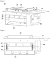
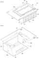
- the bracket 220 may further include a second wall 222 having a through-hole 222a through which cold air generated by a cooling part passes.
- the second wall 222 may extend from the first wall 221. At least a portion of the second wall 222 may extend in the vertical direction. At least a portion of the through-hole 222a may be disposed at a position higher than that of the support wall 221d. In FIG. 6 , for example, the lowermost end of the through-hole 222a is disposed at a position higher than that of the support wall 221d.
- the second tray 380 and the second pusher 540 may contact each other while the second tray assembly rotates while the second pusher 540 is fixed to the fourth wall 224. Ice may be separated from the second tray 380 while the second pusher 540 presses the second tray 380. When the second pusher 540 presses the second tray 380, the ice also presses the second pusher 540 before the ice is separated from the second tray 380. Force for pressing the second pusher 540 may be transmitted to the fourth wall 224. Since the fourth wall 224 is provided in a thin plate shape, a strength reinforcement member 224c may be provided on the fourth wall 224 to prevent the fourth wall 224 from being deformed or broken.
- the strength reinforcement member 224c may include ribs disposed in a lattice form. That is, the strength reinforcement member 224c may include a first rib extending in the first direction and a second rib extending in a second direction crossing the first direction.
- two or more of the first to fourth walls 221 to 224 may define a space in which the first and second tray assemblies are disposed. It should be noted that the names of the walls configuring the bracket 220 are exemplary and the terms distinguishing between the walls are not limited.
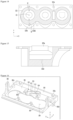
- FIG. 8 is a perspective view of the first tray when viewed from an upper side
- FIG. 9 is a perspective view of the first tray when viewed from a lower side
- FIG. 10 is a plan view of the first tray
- FIG. 11 is a cross-sectional view taken along line 11-11 of FIG. 8 .
- the first tray 320 may include a plurality of openings 324 corresponding to the plurality of first cells 321a.
- One of the plurality of openings 324 324a may provide a passage of the cold air, a passage of the water, and a passage of the first pusher 260.
- the bubbles may escape through the opening 324.
- the first pusher 260 may pass through the opening 324 after passing through the storage chamber wall 325a.
- the storage chamber wall 325a may define the auxiliary storage chamber 325 and also reduce deformation of the periphery of the opening 324 in the process in which the first pusher 260 passes through the opening 324 during the ice separation process.
- the first tray 320 defines a plurality of first cells 321a
- at least one 325b of the plurality of storage chamber walls 325a may support the water supply part 240.
- the storage chamber wall 325b supporting the water supply part 240 may have a polygonal shape.
- the storage chamber wall 325b may include a round part rounded in a horizontal direction and a plurality of straight portions.
- the storage chamber wall 325b may include a round wall 325b 1, a pair of straight walls 325b2 and 325b3 extending side by side from both ends of the round wall 325b, and a connection wall 325b4 connecting the pair of straight walls 325b2 to each other.
- the connection wall 325b4 may be a rounded wall or a straight wall.
- An upper end of the connection wall 325b4 may be disposed at a position lower than that of an upper end of the remaining walls 325b1, 325b2, and 325b3.
- the connection wall 325b4 may support the water supply part 240.
- An opening 324a corresponding to the storage chamber wall 325b supporting the water supply part 240 may also be defined in the same shape as the storage chamber wall 325b.
- the first tray 320 may further include a heater accommodation part 321c.
- the ice separation heater 290 may be accommodated in the heater accommodation part 321c.
- the ice separation heater 290 may contact a bottom surface of the heater accommodation part 321c.
- the heater accommodation part 321c may be provided on the first tray wall 321 as an example.
- the heater accommodation part 321c may be recessed downward from the case accommodation part 321b.
- the heater accommodation part 321c may be disposed to surround the periphery of the first cell 321a. For example, at least a portion of the heater accommodation part 321c may be rounded in the horizontal direction.
- the bottom surface of the heater accommodating portion 321c may be disposed at a position lower than that of the opening 324.
- the first tray 320 may include a first contact surface 322c contacting the second tray 380.
- the bottom surface of the heater accommodating portion 321c may be disposed between the opening 324 and the first contact surface 322c. At least a portion of the heater accommodation part 321c may be disposed to overlap the ice making cell 320a (or the first cell 321a) in a vertical direction.
- the length of the first tray 320 may be longer, but the width of the first tray 320 may be shorter than the length of the first tray 320 to prevent the volume of the first tray 320 from increasing.
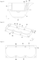
- FIG. 12 is a bottom view of the first tray of FIG. 9
- FIG. 13 is a cross-sectional view taken along line 13-13 of FIG. 11
- FIG. 14 is a cross-sectional view taken along line 14-14 of FIG. 11 .
- the second portion 323 may include a first extension part 323a and a second extension part 323b, which extend in different directions with respect to the central line C1.
- the first tray wall 321 may include one portion of the second extension part 323b of each of the first portion 322 and the second portion 323.
- the first extension wall 327 may include the other portion of each of the first extension part 323a and the second extension part 323b.
- the first extension part 323a may be disposed at the left side with respect to the central line C1
- the second extension part 323b may be disposed at the right side with respect to the central line C1.
- the first extension part 323a and the second extension part 323b may have different shapes based on the central line C1.
- the first extension part 323a and the second extension part 323b may be provided in an asymmetrical shape with respect to the central line C1.
- a length of the second extension part 323b in the Y-axis direction may be greater than that of the first extension part 323a. Therefore, while the ice is made and grown from the upper side in the ice making process, the degree of deformation resistance of the second extension part 323b may increase.
- FIG. 13 illustrates a thickness of the first tray wall 321 at a first height H1 from the first contact surface 322c
- FIG. 14 illustrates a thickness of the first tray wall 321 at a second height H2 from the first contact surface 322c.
- a bottom surface of the upper plate 301 may be coupled to contact an upper side of the first tray 320.
- the upper plate 301 may contact at least one of a top surface of the first portion 322 and a top surface of the second portion 323 of the first tray 320.
- a plate opening 304 (or through-hole) may be defined in the upper plate 301.
- the plate opening 304 may include a straight portion and a curved portion.
- the guide slot 302 may extend in the Z-axis direction of FIG. 16 .
- the first pusher 260 may be inserted into the guide slot 302 to move. Also, the first pusher 260 may move up and down along the guide slot 302.
- the coupling part 301a may be coupled to a coupling member to fix the first tray 320.
- the coupling member coupled to the coupling part 301a may be, for example, a bolt.
- the coupling member may pass through the coupling hole 341a of the first tray supporter 340 and the first coupling hole 327a of the first tray 320 at the bottom surface of the first tray supporter 340 and then be coupled to the coupling part 301a.
- the first guide 312 may include a first portion 312a extending from one side of the plate opening 304 in the Y-axis direction, a second portion 312b bent and extending from the first portion 312a, and a third portion 312c bent from the second portion 312b to extend in the X-axis direction.
- the third portion 312c may be connected to one circumferential wall 303.
- a first protrusion 313 may be disposed on an upper end of the second portion 312b to prevent the wire from being separated.
- the second guide 314 may include a first extension part 314a disposed to face the second portion 312b of the first guide 312 and a second extension part 314b bent to extend from the first extension part 314a and disposed to face the third portion 312c.
- the second portion 312b of the first guide 312 and the first extension part 314a of the second guide 314 and also the third portion 312c of the first guide 312 and the second extension part 314b of the second guide 314 may be parallel to each other.
- a second protrusion 315 may be disposed on an upper end of the first extension part 314a to prevent the wire from being separated.
- the first tray supporter 340 may be coupled to the first tray cover 300 to support the first tray 320.
- the first tray supporter 340 includes a horizontal portion 341 contacting a bottom surface of the upper end of the first tray 320 and an insertion opening 342 through which a lower portion of the first tray 320 is inserted into a center of the horizontal portion 341.
- the horizontal portion 341 may have a size corresponding to the upper plate 301 of the first tray cover 300.
- the horizontal portion 341 may include a plurality of coupling holes 341a engaged with the coupling parts 301a of the first tray cover 300.
- the plurality of coupling holes 341a may be spaced apart from each other in the X-axis and/or Y-axis direction of FIG. 20 to correspond to the coupling part 301a of the first tray cover 300.
- the second tray 380 may include a circumferential wall 387 extending along a circumference of an upper end of the second tray wall 381.
- the circumferential wall 387 may be formed integrally with the second tray wall 381 and may extend from an upper end of the second tray wall 381.
- the circumferential wall 387 may be provided separately from the second tray wall 381 and disposed around the upper end of the second tray wall 381. In this case, the circumferential wall 387 may contact the second tray wall 381 or be spaced apart from the third tray wall 381.
- the circumferential wall 387 may surround at least a portion of the first tray 320. If the second tray 380 includes the circumferential wall 387, the second tray 380 may surround the first tray 320.
- first portion 322 of the first tray 320 may be referred to as a third portion so as to be distinguished from the first portion 382 of the second tray 380.
- second portion 323 of the first tray 320 may be referred to as a fourth portion so as to be distinguished from the second portion 383 of the second tray 380.
- the extension direction of at least a portion of the first part 384a may be the same as that of the second part 384b.
- the extension directions of the second part 384b and the third part 384c may be different from each other.
- the extension direction of the third part 384c may be different from that of the first part 384a.
- the third part 384a may have a constant curvature based on the Y-Z cutting surface. That is, the same curvature radius of the third part 384a may be constant in the longitudinal direction.
- the curvature of the second part 384b may be zero. When the second part 384b is not a straight line, the curvature of the second part 384b may be less than that of the third part 384a.
- the curvature radius of the second part 384b may be greater than that of the third part 384a.
- a distance between an upper portion of the first extension part 383a and an upper portion of the second extension part 383b may be greater than that between a lower portion of the first extension part 383a and a lower portion of the second extension part 383b with respect to the Y-Z cutting surface passing through the central line C1.
- a distance between the first extension part 383a and the second extension part 383b may increase upward.
- the third part 384c may also be described as including the first extension part 383a and the second extension part 383b extending in different directions with respect to the central line C1.
- the second extension part 383b may include an inner line 383b1 and an outer line 383b2.
- a curvature of the inner line 383b1 may be greater than zero with respect to the X-Y cutting surface.
- a curvature of the outer line 383b2 may be equal to or greater than zero.
- the second extension part 383b may be divided into an upper portion and a lower portion in a height direction.
- An amount of change in curvature of the inner line 383b1 of the upper portion of the second extension part 383b may be greater than zero with respect to the X-Y cutting surface.
- An amount of change in curvature of the inner line 383b1 of the lower portion of the second extension part 383b may be greater than zero.
- the maximum curvature change amount of the inner line 383b1 of the upper portion of the second extension part 383b may be greater than that of the inner line 383b1 of the lower portion of the second extension part 383b.
- An amount of change in curvature of the outer line 383b2 of the upper portion of the second extension part 383b may be greater than zero with respect to the X-Y cutting surface.
- An amount of change in curvature of the outer line 383b2 of the lower portion of the second extension part 383b may be greater than zero.
- the minimum curvature change amount of the outer line 383b2 of the upper portion of the second extension part 383b may be greater than that of the outer line 383b2 of the lower portion of the second extension part 383b.
- the outer line of the lower portion of the second extension part 383b may include a straight portion 383b3.
- the third part 384c may include a plurality of first extension parts 383a and a plurality of second extension parts 383b, which correspond to the plurality of ice making cells 320a.
- widths (which are lengths in the X-axis direction) W1 of the two first connection parts 385a may be different from each other according to the formation of the sensor accommodation part 321e.
- the second connection part 385b may include an inner line 385b1 and an outer line 385b2.
- the third part 384c may include two second connection parts 385b.
- the transparent ice heater 430 may contact the first region 382d.
- the first region 382d may include a heater contact surface 382g contacting the transparent ice heater 430.
- the heater contact surface 382g may be, for example, a horizontal plane.
- the heater contact surface 382g may be disposed at a position higher than that of the lowermost end of the first portion 382.
- the second tray cover 360 may include a vertical wall 361 and a curved wall 363 surrounding the opening 362.
- the vertical wall 361 may define three surfaces of the second tray cover 360, and the curved wall 363 may define the other surface of the second tray cover 360.
- the vertical wall 361 may be a wall extending vertically upward, and the curved wall 363 may be a wall rounded away from the opening 362 upward.
- the vertical walls 361 and the curved walls 363 may be provided with a plurality of coupling parts 361a, 361c, and 363a to be coupled to the second tray 380 and the second tray case 400.
- FIG. 32 is a top perspective view of a second tray supporter
- FIG. 33 is a bottom perspective view of the second tray supporter
- FIG. 34 is a cross-sectional view taken along line 34-34 of FIG. 32 .
- the support body 407 may include a lower opening 406b (or a through-hole) through which a portion of the second pusher 540 passes.
- a lower opening 406b (or a through-hole) through which a portion of the second pusher 540 passes.
- three lower openings 406b may be provided in the support body 407 to correspond to the three accommodation spaces 406a.
- a portion of the lower portion of the second tray 380 may be exposed by the lower opening 406b.
- At least a portion of the second tray 380 may be disposed in the lower opening 406b.
- a portion of the second tray 380 may contact the support body 404 by the lower opening 406b.
- a surface area of the area contacting the support body 407 may be greater than that of the non-contact area.
- first coupling part 401a and the second and third coupling parts 401b and 401c may be spaced apart from each other in the Y-axis direction.
- the third coupling part 401c may be disposed farther from the first coupling part 401a than the second coupling part 401b.
- the second tray supporter 400 may further include a spring coupling part 402a to which a spring 402 is coupled.
- the spring coupling part 402a may provide a ring to be hooked with a lower end of the spring 402.
- One of the walls spaced apart from and facing each other in the X-axis direction of the vertical extension wall 405 is provided with a guide hole 408 guiding the transparent ice heater 430 to be described later or the wire connected to the transparent ice heater 430.
- the second tray supporter 400 may further include a link connection part 405a to which the pusher link 500 is coupled.
- the link connection part 405a may protrude from the vertical extension wall 405 in the X-axis direction.
- the link connection part 405a may be disposed on an area between the center line CL1 and the through-hole 404 with respect to FIG. 34 .
- the bottom surface of the lower plate 401 may be further provided with a plurality of second heater coupling parts 409 coupled to the second heater case 420.
- the plurality of second heater coupling parts 409 may be arranged to be spaced apart from each other in the X-axis direction and/or the Y-axis direction.
- the second tray supporter 400 may include a first portion 411 supporting the second tray 380 defining at least a portion of the ice making cell 320a.
- the first portion 411 may be an area between two dotted lines.
- the support body 407 may define the first portion 411.
- the second tray supporter 400 may further include a second portion 413 extending from a predetermined point of the first portion 411.
- a top surface 407a of the support body 407 may provide, for example, the first part 414a.
- the first part 414a may further include a fourth part 414d extending in the vertical line direction.
- the lower plate 401 may provide, for example, the fourth part 414d.
- the vertical extension wall 405 may provide, for example, the third part 414c.
- a length of the third part 414c may be greater than that of the second part 414b.
- the second part 414b may extend in the same direction as the first part 414a.
- the third part 414c may extend in a direction different from that of the first part 414a.
- the second portion 413 may be disposed at the same height as the lowermost end of the first cell 321a or extend up to a lower point.
- the length of the second portion 413 may be greater than the radius of the ice making cell 320a. In this case, the length of the second portion 413 may be lengthened, thereby increasing a heat transfer path.
- the first extension part 413a and the second extension part 413b may have different shapes with respect to the center line CL1.
- the first extension part 413a and the second extension part 413b may have shapes that are asymmetrical to each other with respect to the center line CL1.
- a length of the second extension part 413b may be greater than that of the first extension part 413a in the horizontal direction. That is, a length of the thermal conductivity of the second extension 413b is greater than that of the first extension part 413a.
- a center of curvature of at least a portion of the second extension part 413a may coincide with a center of rotation of the shaft 440 which is connected to the driver 480 to rotate. Accordingly, it is possible to prevent the second extension part 413a from interfering with the neighboring configuration in the rotation process of the second tray assembly.
- the first extension part 413a may include a portion 414e extending upwardly with respect to the horizontal line.
- the portion 414e may surround, for example, a portion of the second tray 380. Accordingly, coupling force of the first tray assembly and the second tray assembly may increase, thereby increasing water leakage prevention effect.
- the second tray supporter 400 may include a first region 415a including the lower opening 406b and a second region 415b having a shape corresponding to the ice making cell 320a to support the second tray 380.
- the first region 415a and the second region 415b may be divided vertically.
- the first region 415a and the second region 415b are divided by a dashed-dotted line extending in the horizontal direction.
- the first region 415a may support the second tray 380.
- the first portion 411 may include the first region 415a and the second region 415b.
- the transparent ice heater 430 will be described in detail.
- At least one of the first tray 320 or the second tray 380 may be made of a flexible or soft material so that the tray deformed by the pushers 260 and 540 is easily restored to its original shape in the ice separation process.
- FIG. 38 is a view of the first pusher according to an embodiment, wherein FIG. 38(a) is a perspective view of the first pusher, and FIG. 38(b) is a side view of the first pusher.
- the first pusher 260 may include a pushing bar 264.
- the pushing bar 264 may include a first edge 264a on which a pressing surface pressing ice or a tray in the ice separation process is disposed and a second edge 264b disposed at a side opposite to the first edge 264a.
- the pressing surface may be flat or curved surface.
- the pushing bar 264 may extend in the vertical direction and may be provided in a straight line shape or a curved shape in which at least a portion of the pushing bar 264 is rounded. A diameter of the pushing bar 264 is less than that of the opening 324 of the first tray 320. Accordingly, the pushing bar 264 may be inserted into the ice making cell 320a through the opening 324. Thus, the first pusher 260 may be referred to as a penetrating type passing through the ice making cell 320a.
- the first pusher 260 may include a guide connection part 265 passing through the guide slot 302.
- the guide connection part 265 may be provided at each of both sides of the first pusher 260.
- a vertical cross-section of the guide connection part 265 may have a circular, oval, or polygonal shape.
- the guide connection part 265 may be disposed in the guide slot 302.
- the guide connection part 265 may move in a longitudinal direction along the guide slot 302 in a state of being disposed in the guide slot 302.
- the guide connection part 265 may move in the vertical direction.
- the guide slot 302 has been described as being provided in the first tray cover 300, it may be alternatively provided in the wall defining the bracket 220 or the storage chamber.
- FIG. 36 is a view illustrating a state in which the first pusher is connected to the second tray assembly by the link.
- the pusher link 500 may connect the first pusher 500 to the second tray assembly.
- the pusher link 500 may be connected to the first pusher 260 and the second tray case.
- the second pusher 540 may include a pushing bar 544.
- the pushing bar 544 may include a first edge 544a on which a pressing surface pressing the second tray 380 is disposed and a second edge 544b disposed at a side opposite to the first edge 544a.
- the pushing bar 544 may have a curved shape to increase in time taken to press the second tray 380 without interfering with the second tray 380 that rotates in the ice separation process.
- the first edge 544a may be a plane and include a vertical surface or an inclined surface.
- the second edge 544b may be coupled to the fourth wall 224 of the bracket 220, or the second edge 544b may be coupled to the fourth wall 224 of the bracket 220 by the coupling plate 542.
- the coupling plate 542 may be seated in the mounting groove 224a defined in the fourth wall 224 of the bracket 220.
- the second pusher 540 may include a plurality of pushing bars 544.
- the plurality of pushing bars 544 may be connected to the coupling plate 542 while being spaced apart from each other in the horizontal direction.
- the plurality of pushing bars 544 may be integrally formed with the coupling plate 542 or coupled to the coupling plate 542.
- the first edge 544a may be disposed to be inclined with respect to the center line C1 of the ice making cell 320a.
- the first edge 544a may be inclined in a direction away from the center line C1 of the ice making cell 320a from an upper end toward a lower end.
- An angle of the inclined surface defined by the first edge 544a with respect to the vertical line may be less than that of the inclined surface defined by the second edge 544b.
- the direction extending from the center of the first edge 544a toward the center of the second edge 544a along the pushing bar 544 may include at least two directions.
- the pushing bar 544 may include a first portion extending in a first direction and a second portion extending in a direction different from the second portion. At least a portion of the line connecting the center of the second edge 544a to the center of the first edge 544a along the pushing bar 544 may be curved.
- the first edge 544a and the second edge 544b may have different heights.
- the first edge 544a may be disposed to be inclined with respect to the second edge 544b.
- FIGS. 38 to 40 are views illustrating an assembly process of the ice maker according to an embodiment.
- FIGS. 38 to 40 are views sequentially illustrating an assembling process, i.e., illustrating a process of coupling components to each other.
- the ice separation heater 290 may be coupled to the first heater case 280, and the first heater case 280 may be assembled to the first tray case.
- the first heater case may be assembled to the first tray cover 300.
- the ice separation heater 290 may be coupled to the first tray cover 300.
- the first tray 320 and the first tray case may be coupled to each other.
- the first tray cover 300 is disposed above the first tray 320
- the first tray supporter 340 may be disposed below the first tray 320
- the coupling member is used to couple the first tray cover 300, the first tray 320, and the first tray supporter 340 to each other.
- the first pusher 260 may be connected to the pusher link 500 in a state in which the first pusher 260 is disposed to be movable in the first tray assembly.
- One end of the pusher link 500 may be connected to the first pusher 260, and the other end may be connected to the second tray assembly.
- the first pusher 260 may be disposed to contact the first tray case.
- the assembled first tray assembly may be installed on the bracket 220.
- the first tray assembly may be coupled to the bracket 220 in a state in which the first tray assembly is disposed in the through-hole 221a of the first wall 221.
- the bracket 220 and the first tray cover may be integrally formed. Then, the first tray assembly may be assembled by coupling the bracket 220 to which the first tray cover is integrated, the first tray 320, and the first tray supporter to each other.
- FIG. 41 is a cross-sectional view taken along line 41-41 of FIG. 2 .
- the predetermined point of the first portion 212 may be an end of the first portion 212 or a point at which the first tray assembly 201 and the second tray assembly 211 meet each other. At least a portion of the first portion 212 may extend in a direction away from the ice making cell 320a defined by the first tray assembly 201. At least two portions of the second portion 213 may be branched to reduce heat transfer in the direction extending to the second portion 213. A portion of the second portion 213 may extend in the horizontal direction passing through the center of the ice making cell 320a. A portion of the second portion 213 may extend in an upward direction with respect to a horizontal line passing through the center of the ice making chamber 320a.
- the second portion 213 includes a first part 213c extending in the horizontal direction passing through the center of the ice making cell 320a, a second part 213d extending upward with respect to the horizontal line passing through the center of the ice making cell 320a, a third part 213e extending downward.
- the first portion 212 may have different degree of heat transfer in a direction along the outer circumferential surface of the ice making cell 320a to reduce transfer of heat, which is transferred from the transparent ice heater 430 to the second tray assembly 211, to the ice making cell 320a defined by the first tray assembly 201.
- the transparent ice heater 430 may be disposed to heat both sides of the first portion 212 with respect to the lowermost end of the first portion 212.
- the refrigerator may include a cooler supplying a cold to the freezing compartment 32 (or the ice making cell).
- the cold air supply part 900 may include one or more of the compressor, the fan, and the refrigerant valve.
- the cold air supply part 900 may further include the evaporator exchanging heat between the refrigerant and the air. The cold air heat-exchanged with the evaporator may be supplied to the ice maker 200.
- the controller 800 may control a portion or all of the ice separation heater 290, the transparent ice heater 430, the driver 480, the cold air supply part 900, and the water supply valve 242.
- an output of the ice separation heater 290 and an output of the transparent ice heater 430 may be different from each other.
- an output terminal of the ice separation heater 290 and an output terminal of the transparent ice heater 430 may be provided in different shapes, incorrect connection of the two output terminals may be prevented.
- the output of the ice separation heater 290 may be set larger than that of the transparent ice heater 430. Accordingly, ice may be quickly separated from the first tray 320 by the ice separation heater 290.
- the transparent ice heater 430 may be disposed at a position adjacent to the second tray 380 described above or be disposed at a position adjacent to the first tray 320.
- the movement to the water supply position of the second tray assembly 211 is detected by a sensor, and when it is detected that the second tray assembly 211 moves to the water supply position, the controller 800 stops the driver 480. At least a portion of the second tray 380 may be spaced apart from the first tray 320 at the water supply position of the second tray assembly 211.
- each of the second portion 383 of the second tray 380 and the second portion 323 of the first tray 320 may be lower than the uppermost end of the auxiliary storage chamber 325.
- the second portion 383 of the second tray 380 may be spaced apart from the second portion 323 of the first tray 320.
- the space may extend to a portion having a height equal to or greater than the uppermost end of the ice making cell 320a defined by the first portion 322 of the first tray 320.
- the space may extend to a point lower than the uppermost end of the auxiliary storage chamber 325.
- the ice separation heater 290 provides heat to reduce freezing of water in the space between the second portion 383 of the second tray 380 and the second portion 323 of the first tray 320.
- a second surface facing the first portion 322 of the first tray 320 at the first portion 382 of the second tray 380 may have a surface area greater than that of the first surface facing the first portion 382 of the second tray 380 at the first portion 322 of the first tray 320. Due to a difference in surface area, coupling force between the first tray assembly 201 and the second tray assembly 211 may increase.
- the ice temperature of the ice making cell 320a is below zero, i.e., lower than the below reference temperature. Therefore, it may be indirectly determined that ice is made in the ice making cell 320a. As described above, when the transparent ice heater 430 is not used, the heat of the transparent ice heater 430 is transferred into the ice making cell 320a.
- an ice making rate per unit height may be different. For example, if the mass per unit height of water is small, the ice making rate is high, whereas if the mass per unit height of water is high, the ice making rate is slow. As a result, the ice making rate per unit height of water is not constant, and thus, the transparency of the ice may vary according to the unit height. In particular, when ice is made at a high rate, the bubbles may not move from the ice to the water, and the ice may contain the bubbles to lower the transparency. That is, the more the variation in ice making rate per unit height of water decreases, the more the variation in transparency per unit height of made ice may decrease.
- control part 800 may control the cooling power and/or the heating amount so that the cooling power of the cold air supply part 900 and/or the heating amount of the transparent ice heater 430 is variable according to the mass per unit height of the water of the ice making cell 320a.
- a reference of the unit height of water in the ice making cell 320a may vary according to a relative position of the ice making cell 320a and the transparent ice heater 430.
- the transparent ice heater 430 at the bottom surface of the ice making cell 320a may be disposed to have the same height.
- a line connecting the transparent ice heater 430 is a horizontal line, and a line extending in a direction perpendicular to the horizontal line serves as a reference for the unit height of the water of the ice making cell 320a.
- ice is made from the uppermost side of the ice making cell 320a and then is grown.
- the transparent ice heater 430 at the bottom surface of the ice making cell 320a may be disposed to have different heights.
- ice is made with a pattern different from that of FIG. 44(a) .
- ice may be made at a position spaced apart from the uppermost end to the left side of the ice making cell 320a, and the ice may be grown to a right lower side at which the transparent ice heater 430 is disposed.
- a line (reference line) perpendicular to the line connecting two points of the transparent ice heater 430 serves as a reference for the unit height of water of the ice making cell 320a.
- the reference line of FIG. 44(b) is inclined at a predetermined angle from the vertical line.
- the mass per unit height of water in the ice making cell 320a increases from the upper side to the lower side to reach the maximum and then decreases again.
- the water (or the ice making cell itself) in the spherical ice making cell 320a having a diameter of about 50 mm is divided into nine sections (section A to section I) by 6 mm height (unit height).
- section A to section I the water (or the ice making cell itself) in the spherical ice making cell 320a having a diameter of about 50 mm
- 6 mm height unit height
- the ice making rate in section E is the lowest, the ice making rate in the sections A and I is the fastest.
- the output of the transparent ice heater 430 may be controlled so that the ice making rate for each unit height is the same or similar while the bubbles move from the portion at which ice is made to the water in the ice making process.
- the output W5 of the transparent ice heater 430 in the section E may be set to a minimum value. Since the volume of the section D is less than that of the section E, the volume of the ice may be reduced as the volume decreases, and thus it is necessary to delay the ice making rate. Thus, an output W6 of the transparent ice heater 430 in the section D may be set to a value greater than an output W5 of the transparent ice heater 430 in the section E.
- the output of the transparent ice heater 430 may increase as the lower side in the section E (see W6, W7, W8, and W9).
- the output of the transparent ice heater 430 is gradually reduced from the first section to the intermediate section after the transparent ice heater 430 is initially turned on.
- the heating amount of the transparent ice heater 430 when the mass for each unit height of water is large may be less than that of the transparent ice heater 430 when the mass for each unit height of water is small.
- the heating amount of the transparent ice heater 430 may vary so as to be inversely proportional to the mass per unit height of water.
- the cooling power of the cold air supply part 900 may vary to be proportional to the mass per unit height of water.
- the cooling power of the cold air supply part 900 from the initial section to the intermediate section during the ice making process may increase.
- the cooling power of the cold air supply part 900 may be maximum in the intermediate section in which the mass for each unit height of water is minimum.
- the cooling power of the cold air supply part 900 may be reduced again from the next section of the intermediate section.
- the transparent ice may be made by varying the cooling power of the cold air supply part 900 and the heating amount of the transparent ice heater 430 according to the mass for each unit height of water.
- the heating power of the transparent ice heater 430 may vary so that the cooling power of the cold air supply part 900 is proportional to the mass per unit height of water and inversely proportional to the mass for each unit height of water.
- a convex portion 382f may be deformed in a direction away from the center of the ice making cell 320a by being pressed by the ice.
- the lower portion of the ice may have the spherical shape by the deformation of the convex portion 382f.
- the controller 800 When at least one of the ice separation heater 290 and the transparent ice heater 430 operate for a predetermined time, or when the temperature sensed by the second temperature sensor 700 is equal to or higher than an off reference temperature, the controller 800 is turned off the heaters 290 and 430, which are turned on (S10).
- the turn-off reference temperature may be set to above zero temperature.
- the extension part 264 passing through the opening 324 may press the ice contacting the first tray 320, and thus, the ice may be separated from the tray 320.
- the ice separated from the first tray 320 may be supported by the second tray 380 again.
- the ice When the ice moves together with the second tray 380 while the ice is supported by the second tray 380, the ice may be separated from the tray 250 by its own weight even if no external force is applied to the second tray 380.
- a distance between a first edge 544a of the second pusher 540 and a second contact surface 382c of the second tray 380 may be less than that between the first edge 544a of the second pusher 540 and the lower opening 406b of the second tray supporter 400 so that the pressing force of the second pusher 540 increases.
- a distance between the first edge 544a of the second pusher 540 and the second contact surface 382c of the second tray may be less than 1/2 of a distance from the center of the ice making cell to an outer circumferential surface.
- the controller 800 controls the driver 480 to allow the second tray assembly 211 to move in the reverse direction (S11). Then, the second tray assembly 211 moves from the ice separation position to the water supply position. When the second tray assembly 211 moves to the water supply position of FIG. 46 , the controller 800 stops the driver 480 (S1).
- FIG. 52 is a view illustrating an operation of the pusher link when the second tray assembly moves from the ice making position to the ice separation position.
- FIG. 52(a) illustrates the ice making position
- FIG. 52(b) illustrates the water supply position
- FIG. 52(c) illustrates the position at which the second tray contacts the second pusher
- FIG. 52(d) illustrates the ice separation position.
- FIG. 53 is a view illustrating a position of the first pusher at the water supply position at which the ice maker is installed in the refrigerator
- FIG. 54 is a cross-sectional view illustrating the position of the first pusher at the water supply position at which the ice maker is installed in the refrigerator
- FIG. 55 is a cross-sectional view illustrating a position of the first pusher at the ice separation position at which the ice maker is installed in the refrigerator.
- the pushing bar 264 of the first pusher 260 may include the first edge 264a and the second edge 264b as described above.
- the first pusher 260 may move by receiving power from the driver 480.
- the controller 800 may control the position so that the first edge 264a is disposed at different positions at the water supply position, the ice making position, and the ice separation position.
- the controller 800 control the first edge 264a to allow the first edge 264a to move in the first direction in the process of moving from the ice separation position to the water supply position and to allow the first edge 264a to additionally move in the first direction in the process of moving from the water supply position to the ice making position.
- the controller 800 controls the first edge 264a to allow the first edge 264a to move in the first direction in the process of moving from the ice separation position to the water supply position and allow the first edge to move in a second direction different from the first direction in the process of moving from the water supply position to the ice making position.
- first edge 264a may move in the first direction by the first slot 302a of the guide slot 302, and the second edge 264a may rotate in a second direction or move in a second direction inclined with the first direction by the second slot 302b.
- the first edge 264a may be disposed at a first point outside the ice making cell 320a at the ice making position and may be controlled to be disposed at a second point of the ice making cell 320a during the ice separation process.
- the lower end 302d of the guide slot 302 may be disposed outside the accommodation space 104.
- the lower end 302d of the guide slot 302 may be higher than the support wall 221d of the bracket 220 and be lower than the upper surface 303b of the circumferential wall 303 of the first tray cover 300. Accordingly, a length of the guide slot 302 may increase without increasing the height of the ice maker 200.
- the through-hole 244 may be defined in a direction in which the water supply part 240 faces the ice making cell 320a.
- the lowermost end 240a of the water supply part 240 may be disposed lower than an upper end of the auxiliary storage chamber 325.
- the lowermost end 240a of the water supply part 240 may be disposed in the auxiliary storage chamber 325.
- the control unit 800 may control a position of the first edge 264a so that the first edge moves in the direction away from the through-hole 244 of the water supply unit 240 in the process of allowing the second tray assembly 211 to move from the ice separation position to the water supply position.
- the first edge 264a may rotate in a direction away from the through-hole 244.
- the contact of the water with the first edge 264a in the water supply process may be reduced, and thus, the freezing of the water at the first edge 264a is reduced.
- the second edge 264b may further move in the second direction.
- the first edge 264a may be disposed outside the ice making cell 320a. At the water supply position, the first edge 264a may be disposed outside the auxiliary storage chamber 325. At the water supply position, the first edge 264a may be disposed higher than the lower end of the through-hole 224. At the water supply position, a maximum value of a distance between the center line C1 of the ice making cell 320a and the first edge 264a may be greater than that of a distance between the center line C1 of the ice making cell 320a and the storage wall 325a.
- the first edge 264a may be disposed higher than the upper end 325c of the auxiliary storage chamber 325 and be disposed lower than the upper end 325b of the circumferential wall 303 of the first tray cover 300. In this case, the first edge 264a may be disposed close to the ice making cell 320a to allow the first edge 264a to press the ice at the initial ice separation process, thereby improving the ice separation performance.
- the second edge 264b may be disposed outside the accommodation space 104.
- the second edge 264b may be disposed between the support surface 221d1 supporting the first tray assembly 201 in the bracket 220 and the first portion of the cover member 100.
- the second edge 264b may be lower than the top surface 221b1 of the first fixing wall 221b of the bracket 220.
- the second edge 264b may be disposed outside the ice making cell 320a.
- the second edge 264b may be disposed outside the auxiliary storage chamber 325.
- the first portion 241 of the water supply part 240 may extend in the vertical direction as a whole or may partially extend in the vertical direction, and the other portion of the first portion 241 may extend in a direction away from the first pusher 260.
- the first portion 241 of the water supply unit 240 may be provided to be farther from the first pusher 260 from the lower end 241a to the upper end 241a.
- a distance between the second edge 264b and the first portion 241 of the water supply 240 at the water supply position may be greater than that between the second edge 264b and the first portion 241 of the water supply part 240 at the ice making position.
- An outlet 121 of the cold air duct 120 may be aligned with the through-hole 222a of the bracket 220.
- the outlet 121 of the cold air duct 120 may be disposed so as not to face at least the guide slot 302. When the cold air flows directly into the guide slot 302, freezing may occur in the guide slot 302 so that the first pusher 260 does not move smoothly.
- At least a portion of the outlet 121 of the cold air duct 120 may be disposed higher than an upper end of the circumferential wall 303 of the first tray cover 300.
- the outlet 121 of the cold air duct 120 may be disposed higher than the opening 324 of the first tray 320. Therefore, the cold air may flow toward the opening 324 from the upper side of the ice making cell 320a.
- the cold air supply part 900 may be disposed so that more amount of cold air (or cold) may be supplied to the area of the first cell 321a, which is farther from the transparent ice heater, than the area of the first cell 321a, which is close to the transparent ice heater 430.
- a distance between the cooler and the area of the first cell 321a, which is close to the transparent ice heater 430 is greater than that between the cooler and the area of the first cell 321a, which is far from the transparent ice heater 430.
- a distance between the cooler and the second cell 381a may be greater than that between the cooler and the first cell 321a.
- cooling power of the cold air supply part 900 may be determined corresponding to the target temperature of the freezing compartment 32.
- the cold air generated by the cold air supply part 900 may be supplied to the freezing chamber 32.
- the water of the ice making cell 320a may be phase-changed into ice by heat transfer between the cold water supplied to the freezing chamber 32 and the water of the ice making cell 320a.
- a heating amount of the transparent ice heater 430 for each unit height of water may be determined in consideration of predetermined cooling power of the cold air supply part 900.
- the case in which the heat transfer amount between the cold and the water increase may be a case in which the cooling power of the cold air supply part 900 increases or a case in which the air having a temperature lower than the temperature of the cold air in the freezing compartment 32 is supplied to the freezing compartment 32.
- a target temperature of the freezing compartment 32 is lowered, an operation mode of the freezing compartment 32 is changed from a normal mode to a rapid cooling mode, an output of at least one of the compressor or the fan increases, or an opening degree increases, the cooling power of the cold air supply part 900 may increase.
- the heating amount of transparent ice heater 430 may be controlled to increase.
- the ice making rate when the ice making rate is maintained within the predetermined range, the ice making rate is less than the rate at which the bubbles move in the portion at which the ice is made, and no bubbles exist in the portion at which the ice is made.
- the controller 800 may control the output of the transparent ice heater 430 so that the ice making rate may be maintained within the predetermined range regardless of the target temperature of the freezing compartment 32.
- the controller 800 may decrease the reference heating amount of transparent ice heater 430 that is predetermined in each of the current section and the remaining sections.
- the variable control of the heating amount of the transparent ice heater 430 may be normally performed until the ice making is completed (S35).
- the controller 800 may increase the reference heating amount of transparent ice heater 430 that is predetermined in each of the current section and the remaining sections.
- the variable control of the heating amount of the transparent ice heater 430 may be normally performed until the ice making is completed (S35).
Landscapes
- Engineering & Computer Science (AREA)
- Physics & Mathematics (AREA)
- Mechanical Engineering (AREA)
- Thermal Sciences (AREA)
- General Engineering & Computer Science (AREA)
- Chemical & Material Sciences (AREA)
- Combustion & Propulsion (AREA)
- Production, Working, Storing, Or Distribution Of Ice (AREA)
- Devices That Are Associated With Refrigeration Equipment (AREA)
- Cold Air Circulating Systems And Constructional Details In Refrigerators (AREA)
Claims (15)
- Réfrigérateur comportant :une chambre de stockage configurée pour stocker des aliments ;un refroidisseur configuré pour fournir du froid dans la chambre de stockage ;un premier capteur de température (33) configuré pour détecter une température à l'intérieur de la chambre de stockage ;un premier ensemble de moule (201) configuré pour définir une portion d'une cellule de fabrication de glaçons (320a) qui est un espace dans lequel de l'eau est transformée en glace, par changement de phase, par le froid ;un second ensemble de moule (211) configuré pour définir une autre portion de la cellule de fabrication de glaçons (320a), le second ensemble de moule (211) étant relié à un dispositif d'entraînement (480) pour être en contact avec le premier ensemble de moule (201) dans un processus de fabrication de glaçons et pour être espacé du premier ensemble de moule (201) dans un processus de séparation de glaçons ;une partie d'alimentation en eau (240) configurée pour fournir l'eau dans la cellule de fabrication de glaçons (320a) ;un second capteur de température (700) configuré pour détecter une température de l'eau ou des glaçons à l'intérieur de la cellule de fabrication de glaçons (320a) ;un élément chauffant (430) disposé au voisinage d'au moins un ensemble parmi le premier ensemble de moule (201) ou le second ensemble de moule (211) ; etune commande (800) configurée pour commander l'élément chauffant (430) et le dispositif d'entraînement (480),dans lequel la commande (800) est configurée pour commander le refroidisseur de sorte que le froid est fourni à la cellule de fabrication de glaçons (320a) après avoir amené le second ensemble de moule (211) à une position de fabrication de glaçons lorsque l'eau est entièrement fournie à la cellule de fabrication de glaçons (320a),la commande (800) est configurée pour commander le second ensemble de moule (211) de sorte que le second ensemble de moule (211) se déplace dans une direction inverse après avoir été amené à une position de séparation de glaçons dans une direction vers l'avant de manière à extraire les glaçons dans la cellule de fabrication de glaçons (320a) lorsque les glaçons sont entièrement fabriqués dans la cellule de fabrication de glaçons (320a),la commande (800) est configurée pour réaliser une commande de sorte qu'une alimentation en eau débute après avoir amené le second ensemble de moule (211) à une position d'alimentation en eau dans la direction inverse lorsque les glaçons sont entièrement séparés,la commande (800) est configurée pour commander la mise en marche de l'élément chauffant (430) dans une section au moins partielle lorsque le refroidisseur fournit le froid de sorte que des bulles dissoutes dans l'eau à l'intérieur de la cellule de fabrication de glaçons (320a) se déplacent à partir d'une portion, au niveau de laquelle les glaçons sont fabriqués, vers l'eau qui est dans un état liquide pour fabriquer des glaçons transparents,pour fabriquer des glaçons dans une direction allant de la portion ou de l'autre portion de la cellule de fabrication de glaçons (320a) définie par un ensemble parmi les premier et second ensembles de moule (201, 211) jusqu'à la portion ou l'autre portion de la cellule de fabrication de glaçons (320a) définie par l'autre ensemble de moule parmi les premier et second ensembles de moule (201, 211) après le début du processus de fabrication de glaçons, l'autre ensemble de moule comporte une première surface définissant une portion de la cellule de fabrication de glaçons (320a) et une seconde surface s'étendant à partir de la première surface et supportée sur au moins une surface de l'ensemble de moule.
- Réfrigérateur selon la revendication 1, dans lequel la seconde surface en contact avec au moins une surface du premier ensemble de moule est espacée de la au moins une surface dans le processus de séparation de glaçons.
- Réfrigérateur selon la revendication 1, dans lequel l'autre ensemble de moule comporte une première zone et une seconde zone située plus loin que l'élément chauffant (430) que la première zone, dans lequel la seconde zone comporte la seconde surface.
- Réfrigérateur selon la revendication 1, comportant en outre un poussoir (540) comportant un premier bord (544a) formé avec une surface destinée à presser un ou plusieurs ensembles parmi les premier et second ensembles de moule (201, 211), ou les glaçons pour séparer facilement les glaçons des premier et second ensembles de moule (201, 211), une barrette (544) s'étendant à partir du premier bord (544a), et un second bord (544b) situé à une extrémité de la barrette (544),
le poussoir (540) comportant de préférence une pluralité de barrettes (544) et la pluralité de barrettes est supportée sur une plaque de couplage (542) dans un état où elles sont espacées les unes des autres. - Réfrigérateur selon la revendication 4, dans lequel la commande (800) est configurée pour commander au second ensemble de moule (211) de se déplacer vers le poussoir (540).
- Réfrigérateur selon la revendication 4, comportant en outre un support (220) supporté par une paroi définissant la chambre de stockage, dans lequel la plaque de couplage (542) est fixée au support (220).
- Réfrigérateur selon la revendication 4, dans lequel le second ensemble de moule (211) comporte une partie de pression (382f) comportant une surface qui est capable d'être mise en contact avec le poussoir (540) et d'être séparée de celui-ci, et une partie périphérique ayant un plus grand degré de résistance à la déformation et un plus petit degré de rappel que la partie de pression (382f).
- Réfrigérateur selon la revendication 7, dans lequel une aire d'une surface circonférentielle extérieure de la cellule de fabrication de glaçons (320a) définie par la partie de pression (382f) est inférieure à celle de la surface circonférentielle extérieure de la cellule de fabrication de glaçons (320a) définie par la partie périphérique.
- Réfrigérateur selon la revendication 4,dans lequel au moins une portion d'une ligne reliant un centre du premier bord (544a) à un centre du second bord (544b) le long de la barrette (544) est une ligne courbe ; et/oudans lequel le premier bord (544a) et le second bord (544b) sont situés à différentes hauteurs ; et/oudans lequel une surface inclinée définie par le premier bord (544a) croise une surface inclinée définie par le second bord (544b).
- Réfrigérateur selon la revendication 4,dans lequel la commande (800) est configurée pour réaliser une commande de sorte qu'un angle de rotation du dispositif d'entraînement (480) est supérieur à celui du second ensemble de moule (211) à la position de séparation de glaçons afin d'augmenter une force de pression du poussoir (540) ; et/oudans lequel la commande (800) est configurée pour commander une position de telle sorte qu'une distance d'une ligne passant par le premier bord (544a) et la seconde surface est inférieure à 1/2 d'une distance d'un centre de la cellule de fabrication de glaçons (320a) à une surface circonférentielle extérieure, à la position de séparation de glaçons.
- Réfrigérateur selon la revendication 4,dans lequel le second ensemble de moule (211) est mis en rotation par le dispositif d'entraînement, dans lequel le premier bord est incliné par rapport à une ligne verticale passant par un centre de la cellule de fabrication de glaçons (320a) et/oudans lequel le second ensemble de moule (211) est mis en rotation par le dispositif d'entraînement, dans lequel une direction s'étendant d'un centre du premier bord à un centre du second bord le long de la barrette comporte au moins deux directions.
- Réfrigérateur selon la revendication 1, dans lequella commande (800) est configurée pour commander l'élément chauffant (430) de sorte que lorsqu'une quantité de transfert de chaleur entre le froid destiné à refroidir la cellule de fabrication de glaçons (320a) et l'eau de la cellule de fabrication de glaçons (320a) augmente, une quantité de chauffage de l'élément chauffant (430) augmente, et lorsque la quantité de transfert de chaleur entre le froid destiné à refroidir la cellule de fabrication de glaçons (320a) et l'eau de la cellule de fabrication de glaçons (320a) diminue, la quantité de chauffage de l'élément chauffant (430) diminue de manière à maintenir une vitesse de fabrication de glaçons de l'eau à l'intérieur de la cellule de fabrication de glaçons (320a) dans une plage prédéterminée qui est inférieure à une vitesse de fabrication de glaçons lorsqu'une fabrication de glaçons est réalisée dans un état dans lequel l'élément chauffant (430) est arrêté,dans lequel le réfrigérateur inclut en outre un poussoir comportant un premier bord formé avec une surface destinée à presser un ou plusieurs ensembles parmi les premier et second ensembles de moule (201, 211), ou les glaçons pour séparer facilement les glaçons des premier et second ensembles de moule, une barrette s'étendant à partir du premier bord, et un second bord situé à une extrémité de la barrette.
- Réfrigérateur selon la revendication 12, dans lequel la commande (800) est configurée pour réaliser une commande de telle sorte qu'un angle de rotation du dispositif d'entraînement (480) est supérieur à celui du second ensemble de moule (211) à la position de séparation de glaçons pour augmenter la force de pression du poussoir (540).
- Réfrigérateur selon la revendication 12 ou 13, dans lequel le premier bord (544a) est incliné dans une direction s'éloignant d'une ligne verticale passant par un centre de la cellule de fabrication de glaçons (320a) d'un côté supérieur à un côté inférieur du premier bord (544a).
- Réfrigérateur selon la revendication 1, dans lequella seconde surface en contact avec au moins une surface de l'ensemble de moule est espacée de la au moins une surface pendant le processus de séparation de glaçons,dans lequel le réfrigérateur inclut en outre un poussoir (540) comportant un premier bord (544a) formé avec une surface destinée à presser un ou plusieurs ensembles parmi les premier et second ensembles de moule (201, 211), ou les glaçons pour séparer facilement les glaçons des premier et second ensembles de moule (201, 211), une barrette (544) s'étendant à partir du premier bord (544a), et un second bord (544b) situé à une extrémité de la barrette (544), etle second ensemble de moule (211) comporte une partie de pression (382f) comportant une surface qui est capable d'être mise en contact avec le poussoir (540) et d'être séparée de celui-ci, et une partie périphérique ayant un plus grand degré de résistance à la déformation et un plus petit degré de rappel que la partie de pression (382f).
Priority Applications (1)
| Application Number | Priority Date | Filing Date | Title |
|---|---|---|---|
| EP25161964.9A EP4542146A3 (fr) | 2018-10-02 | 2019-10-01 | Réfrigérateur |
Applications Claiming Priority (8)
| Application Number | Priority Date | Filing Date | Title |
|---|---|---|---|
| KR1020180117785A KR102669631B1 (ko) | 2018-10-02 | 2018-10-02 | 제빙기 및 이를 포함하는 냉장고 |
| KR1020180117822A KR102731115B1 (ko) | 2018-10-02 | 2018-10-02 | 제빙기 및 이를 포함하는 냉장고 |
| KR1020180117821A KR102636442B1 (ko) | 2018-10-02 | 2018-10-02 | 제빙기 및 이를 포함하는 냉장고 |
| KR1020180117819A KR102709377B1 (ko) | 2018-10-02 | 2018-10-02 | 제빙기 및 이를 포함하는 냉장고 |
| KR1020180142117A KR102657068B1 (ko) | 2018-11-16 | 2018-11-16 | 아이스 메이커의 제어방법 |
| KR1020190081697A KR102779321B1 (ko) | 2019-07-06 | 2019-07-06 | 냉장고 |
| KR1020190081698A KR102772204B1 (ko) | 2019-07-06 | 2019-07-06 | 냉장고 |
| PCT/KR2019/012859 WO2020071748A1 (fr) | 2018-10-02 | 2019-10-01 | Réfrigérateur |
Related Child Applications (2)
| Application Number | Title | Priority Date | Filing Date |
|---|---|---|---|
| EP25161964.9A Division EP4542146A3 (fr) | 2018-10-02 | 2019-10-01 | Réfrigérateur |
| EP25161964.9A Division-Into EP4542146A3 (fr) | 2018-10-02 | 2019-10-01 | Réfrigérateur |
Publications (3)
| Publication Number | Publication Date |
|---|---|
| EP3862663A1 EP3862663A1 (fr) | 2021-08-11 |
| EP3862663A4 EP3862663A4 (fr) | 2022-08-10 |
| EP3862663B1 true EP3862663B1 (fr) | 2025-04-16 |
Family
ID=70054921
Family Applications (2)
| Application Number | Title | Priority Date | Filing Date |
|---|---|---|---|
| EP25161964.9A Pending EP4542146A3 (fr) | 2018-10-02 | 2019-10-01 | Réfrigérateur |
| EP19868592.7A Active EP3862663B1 (fr) | 2018-10-02 | 2019-10-01 | Réfrigérateur |
Family Applications Before (1)
| Application Number | Title | Priority Date | Filing Date |
|---|---|---|---|
| EP25161964.9A Pending EP4542146A3 (fr) | 2018-10-02 | 2019-10-01 | Réfrigérateur |
Country Status (5)
| Country | Link |
|---|---|
| US (2) | US11892221B2 (fr) |
| EP (2) | EP4542146A3 (fr) |
| CN (2) | CN112771331B (fr) |
| AU (3) | AU2019352422B2 (fr) |
| WO (1) | WO2020071748A1 (fr) |
Families Citing this family (4)
| Publication number | Priority date | Publication date | Assignee | Title |
|---|---|---|---|---|
| EP3862679B1 (fr) * | 2018-10-02 | 2025-04-09 | LG Electronics Inc. | Réfrigérateur |
| KR20210147419A (ko) * | 2020-05-28 | 2021-12-07 | 코웨이 주식회사 | 얼음 정수기 |
| KR20220144216A (ko) * | 2021-04-19 | 2022-10-26 | 엘지전자 주식회사 | 냉장고 |
| WO2023153652A1 (fr) | 2022-02-10 | 2023-08-17 | 삼성전자주식회사 | Réfrigérateur et son procédé de commande |
Family Cites Families (53)
| Publication number | Priority date | Publication date | Assignee | Title |
|---|---|---|---|---|
| US2342743A (en) * | 1942-03-06 | 1944-02-29 | Lutes Herschel | Refrigerating apparatus |
| US3678701A (en) * | 1970-12-16 | 1972-07-25 | Gen Electric | Ice maker |
| JPH0822958B2 (ja) | 1987-12-16 | 1996-03-06 | 三井東圧化学株式会社 | ポリイミド系樹脂組成物 |
| US4910974A (en) * | 1988-01-29 | 1990-03-27 | Hoshizaki Electric Company Limited | Automatic ice making machine |
| JPH01158070U (fr) * | 1988-04-21 | 1989-10-31 | ||
| JPH04313661A (ja) | 1991-04-10 | 1992-11-05 | Toshiba Corp | 製氷装置 |
| JPH05203299A (ja) * | 1992-01-23 | 1993-08-10 | Matsushita Refrig Co Ltd | 自動製氷装置 |
| JPH05203302A (ja) | 1992-01-30 | 1993-08-10 | Matsushita Refrig Co Ltd | 自動製氷装置 |
| JPH06241626A (ja) * | 1993-02-23 | 1994-09-02 | Sharp Corp | 自動製氷装置 |
| JPH09269172A (ja) | 1996-03-29 | 1997-10-14 | Toshiba Corp | 製氷装置 |
| JP4028688B2 (ja) * | 2001-03-21 | 2007-12-26 | 株式会社東芝 | 冷蔵庫 |
| US7100379B2 (en) * | 2003-08-14 | 2006-09-05 | Samsung Electronics Co., Ltd. | Water supply control apparatus and method for ice maker |
| KR100644824B1 (ko) * | 2003-10-13 | 2006-11-13 | 엘지전자 주식회사 | 냉장고의 제어 방법 |
| KR20050069319A (ko) | 2003-12-31 | 2005-07-05 | 삼성전자주식회사 | 냉장고용 자동 제빙장치 |
| KR20050096336A (ko) * | 2004-03-30 | 2005-10-06 | 삼성전자주식회사 | 냉장고 및 그 제어방법 |
| JP4657626B2 (ja) | 2004-05-12 | 2011-03-23 | 日本電産サーボ株式会社 | 自動製氷装置 |
| US7185508B2 (en) * | 2004-10-26 | 2007-03-06 | Whirlpool Corporation | Refrigerator with compact icemaker |
| US7131280B2 (en) * | 2004-10-26 | 2006-11-07 | Whirlpool Corporation | Method for making ice in a compact ice maker |
| US7216491B2 (en) * | 2005-04-29 | 2007-05-15 | Emerson Electric Co | Ice maker with adaptive fill |
| US7665316B2 (en) * | 2005-10-25 | 2010-02-23 | Japan Servo Co., Ltd. | Automatic icemaker |
| US20080072610A1 (en) * | 2006-09-26 | 2008-03-27 | General Electric Company | Apparatus and method for controlling operation of an icemaker |
| KR100845858B1 (ko) * | 2006-12-29 | 2008-07-14 | 엘지전자 주식회사 | 제빙장치 및 그 제어방법 |
| US20080216490A1 (en) * | 2007-03-08 | 2008-09-11 | Hoshizaki Denki Kabushiki Kaisha | Operation method for automatic ice maker |
| JP4364916B2 (ja) * | 2007-03-28 | 2009-11-18 | 日本電産サーボ株式会社 | 自動製氷装置 |
| KR101410754B1 (ko) | 2007-06-04 | 2014-06-24 | 삼성전자 주식회사 | 제빙장치 및 이를 구비한 냉장고 |
| KR101457691B1 (ko) * | 2008-03-10 | 2014-11-03 | 엘지전자 주식회사 | 냉장고용 제빙 어셈블리의 제어 방법 |
| JP2011064371A (ja) | 2009-09-16 | 2011-03-31 | Sharp Corp | 冷凍冷蔵庫の製氷装置 |
| JP4680311B2 (ja) | 2009-09-16 | 2011-05-11 | シャープ株式会社 | 冷凍冷蔵庫の製氷装置 |
| KR101643635B1 (ko) | 2009-10-07 | 2016-07-29 | 엘지전자 주식회사 | 제빙장치 및 이를 이용한 제빙방법 |
| JP2011237077A (ja) | 2010-05-07 | 2011-11-24 | Toshiba Corp | 自動製氷装置 |
| JP2012057884A (ja) * | 2010-09-10 | 2012-03-22 | Hitachi Appliances Inc | 冷蔵庫及び冷蔵庫の製造方法 |
| US8950197B2 (en) * | 2011-06-22 | 2015-02-10 | Whirlpool Corporation | Icemaker with swing tray |
| KR101968563B1 (ko) * | 2011-07-15 | 2019-08-20 | 엘지전자 주식회사 | 아이스 메이커 |
| KR101890939B1 (ko) | 2011-07-15 | 2018-08-23 | 엘지전자 주식회사 | 아이스 메이커 |
| KR101888197B1 (ko) * | 2011-09-16 | 2018-08-14 | 엘지전자 주식회사 | 냉장고 |
| KR101850918B1 (ko) | 2011-10-04 | 2018-05-30 | 엘지전자 주식회사 | 아이스 메이커 및 이를 이용한 얼음 제조 방법 |
| KR101966043B1 (ko) * | 2012-06-12 | 2019-04-05 | 엘지전자 주식회사 | 냉장고 |
| KR102009350B1 (ko) * | 2012-06-12 | 2019-08-09 | 엘지전자 주식회사 | 냉장고의 제어 방법 |
| US9200823B2 (en) * | 2012-12-13 | 2015-12-01 | Whirlpool Corporation | Ice maker with thermoelectrically cooled mold for producing spherical clear ice |
| US9080800B2 (en) * | 2012-12-13 | 2015-07-14 | Whirlpool Corporation | Molded clear ice spheres |
| KR102130632B1 (ko) | 2013-01-02 | 2020-07-06 | 엘지전자 주식회사 | 아이스 메이커 |
| KR101981680B1 (ko) * | 2013-10-16 | 2019-05-23 | 삼성전자주식회사 | 제빙 트레이 및 이를 갖는 냉장고 |
| US10274240B2 (en) * | 2014-04-07 | 2019-04-30 | Daechang Co., Ltd. | Ice maker and refrigerator having same |
| JP2016044900A (ja) * | 2014-08-25 | 2016-04-04 | 日立アプライアンス株式会社 | 冷蔵庫 |
| KR101668251B1 (ko) * | 2015-01-26 | 2016-10-21 | 엘지전자 주식회사 | 냉장고 및 그 동작방법 |
| KR102331090B1 (ko) * | 2015-02-27 | 2021-11-25 | 삼성전자주식회사 | 냉장고 |
| US20170023282A1 (en) * | 2015-07-21 | 2017-01-26 | Haier America Research And Development Co., Ltd. | User-controlled icemaker system |
| US20170082338A1 (en) * | 2015-09-18 | 2017-03-23 | Jesse L. Wobrock | Systems and methods for forming shaped ice |
| CN105258418B (zh) * | 2015-10-29 | 2018-02-02 | 合肥海尔电冰箱有限公司 | 冰箱 |
| KR102541390B1 (ko) * | 2016-07-13 | 2023-06-09 | 삼성전자주식회사 | 제빙기 및 이를 갖는 냉장고 |
| KR102758884B1 (ko) | 2017-02-14 | 2025-01-24 | 삼성전자주식회사 | 냉장고 및 그 제어 방법 |
| KR20180100752A (ko) | 2017-03-02 | 2018-09-12 | 주식회사 대창 | 히팅모듈 및 이를 포함하는 제빙기, 비데, 정수기, 냉장고 |
| KR102432022B1 (ko) * | 2018-01-16 | 2022-08-12 | 삼성전자주식회사 | 제빙장치 |
-
2019
- 2019-10-01 CN CN201980064143.XA patent/CN112771331B/zh active Active
- 2019-10-01 EP EP25161964.9A patent/EP4542146A3/fr active Pending
- 2019-10-01 WO PCT/KR2019/012859 patent/WO2020071748A1/fr not_active Ceased
- 2019-10-01 CN CN202211726090.3A patent/CN116222072A/zh active Pending
- 2019-10-01 AU AU2019352422A patent/AU2019352422B2/en active Active
- 2019-10-01 EP EP19868592.7A patent/EP3862663B1/fr active Active
- 2019-10-01 US US17/281,955 patent/US11892221B2/en active Active
-
2023
- 2023-07-25 AU AU2023208102A patent/AU2023208102B2/en active Active
- 2023-12-26 US US18/396,059 patent/US20240125532A1/en active Pending
-
2026
- 2026-02-24 AU AU2026201351A patent/AU2026201351A1/en active Pending
Also Published As
| Publication number | Publication date |
|---|---|
| AU2026201351A1 (en) | 2026-03-12 |
| EP3862663A1 (fr) | 2021-08-11 |
| US20210356188A1 (en) | 2021-11-18 |
| AU2023208102B2 (en) | 2025-11-27 |
| CN112771331A (zh) | 2021-05-07 |
| CN116222072A (zh) | 2023-06-06 |
| EP3862663A4 (fr) | 2022-08-10 |
| AU2019352422A1 (en) | 2021-05-27 |
| EP4542146A3 (fr) | 2025-06-11 |
| EP4542146A2 (fr) | 2025-04-23 |
| AU2019352422B2 (en) | 2023-04-27 |
| US20240125532A1 (en) | 2024-04-18 |
| US11892221B2 (en) | 2024-02-06 |
| AU2023208102A1 (en) | 2023-08-17 |
| WO2020071748A1 (fr) | 2020-04-09 |
| CN112771331B (zh) | 2023-01-17 |
Similar Documents
| Publication | Publication Date | Title |
|---|---|---|
| AU2023208102B2 (en) | Refrigerator | |
| AU2023206157B2 (en) | Refrigerator | |
| AU2025283447A1 (en) | Refrigerator | |
| AU2025271159A1 (en) | Refrigerator | |
| EP3862699B1 (fr) | Réfrigérateur | |
| EP3862670B1 (fr) | Réfrigérateur | |
| EP4556820A2 (fr) | Refrigerator | |
| AU2023204603B2 (en) | Refrigerator | |
| AU2023214235B2 (en) | Refrigerator | |
| EP3862666B1 (fr) | Réfrigérateur |
Legal Events
| Date | Code | Title | Description |
|---|---|---|---|
| STAA | Information on the status of an ep patent application or granted ep patent |
Free format text: STATUS: THE INTERNATIONAL PUBLICATION HAS BEEN MADE |
|
| PUAI | Public reference made under article 153(3) epc to a published international application that has entered the european phase |
Free format text: ORIGINAL CODE: 0009012 |
|
| STAA | Information on the status of an ep patent application or granted ep patent |
Free format text: STATUS: REQUEST FOR EXAMINATION WAS MADE |
|
| 17P | Request for examination filed |
Effective date: 20210430 |
|
| AK | Designated contracting states |
Kind code of ref document: A1 Designated state(s): AL AT BE BG CH CY CZ DE DK EE ES FI FR GB GR HR HU IE IS IT LI LT LU LV MC MK MT NL NO PL PT RO RS SE SI SK SM TR |
|
| DAV | Request for validation of the european patent (deleted) | ||
| DAX | Request for extension of the european patent (deleted) | ||
| A4 | Supplementary search report drawn up and despatched |
Effective date: 20220713 |
|
| RIC1 | Information provided on ipc code assigned before grant |
Ipc: F25C 5/06 20060101ALI20220707BHEP Ipc: F25C 1/10 20060101ALI20220707BHEP Ipc: F25C 5/02 20060101ALI20220707BHEP Ipc: F25C 1/24 20180101ALI20220707BHEP Ipc: F25C 1/18 20060101ALI20220707BHEP Ipc: F25D 25/02 20060101ALI20220707BHEP Ipc: F25D 29/00 20060101ALI20220707BHEP Ipc: F25D 11/00 20060101AFI20220707BHEP |
|
| GRAP | Despatch of communication of intention to grant a patent |
Free format text: ORIGINAL CODE: EPIDOSNIGR1 |
|
| STAA | Information on the status of an ep patent application or granted ep patent |
Free format text: STATUS: GRANT OF PATENT IS INTENDED |
|
| INTG | Intention to grant announced |
Effective date: 20240607 |
|
| GRAJ | Information related to disapproval of communication of intention to grant by the applicant or resumption of examination proceedings by the epo deleted |
Free format text: ORIGINAL CODE: EPIDOSDIGR1 |
|
| STAA | Information on the status of an ep patent application or granted ep patent |
Free format text: STATUS: REQUEST FOR EXAMINATION WAS MADE |
|
| GRAP | Despatch of communication of intention to grant a patent |
Free format text: ORIGINAL CODE: EPIDOSNIGR1 |
|
| STAA | Information on the status of an ep patent application or granted ep patent |
Free format text: STATUS: GRANT OF PATENT IS INTENDED |
|
| INTC | Intention to grant announced (deleted) | ||
| INTG | Intention to grant announced |
Effective date: 20241106 |
|
| GRAS | Grant fee paid |
Free format text: ORIGINAL CODE: EPIDOSNIGR3 |
|
| GRAA | (expected) grant |
Free format text: ORIGINAL CODE: 0009210 |
|
| STAA | Information on the status of an ep patent application or granted ep patent |
Free format text: STATUS: THE PATENT HAS BEEN GRANTED |
|
| AK | Designated contracting states |
Kind code of ref document: B1 Designated state(s): AL AT BE BG CH CY CZ DE DK EE ES FI FR GB GR HR HU IE IS IT LI LT LU LV MC MK MT NL NO PL PT RO RS SE SI SK SM TR |
|
| REG | Reference to a national code |
Ref country code: GB Ref legal event code: FG4D |
|
| REG | Reference to a national code |
Ref country code: CH Ref legal event code: EP |
|
| REG | Reference to a national code |
Ref country code: IE Ref legal event code: FG4D |
|
| REG | Reference to a national code |
Ref country code: DE Ref legal event code: R096 Ref document number: 602019068829 Country of ref document: DE |
|
| REG | Reference to a national code |
Ref country code: NL Ref legal event code: MP Effective date: 20250416 |
|
| PG25 | Lapsed in a contracting state [announced via postgrant information from national office to epo] |
Ref country code: NL Free format text: LAPSE BECAUSE OF FAILURE TO SUBMIT A TRANSLATION OF THE DESCRIPTION OR TO PAY THE FEE WITHIN THE PRESCRIBED TIME-LIMIT Effective date: 20250416 |
|
| REG | Reference to a national code |
Ref country code: AT Ref legal event code: MK05 Ref document number: 1785924 Country of ref document: AT Kind code of ref document: T Effective date: 20250416 |
|
| PG25 | Lapsed in a contracting state [announced via postgrant information from national office to epo] |
Ref country code: PT Free format text: LAPSE BECAUSE OF FAILURE TO SUBMIT A TRANSLATION OF THE DESCRIPTION OR TO PAY THE FEE WITHIN THE PRESCRIBED TIME-LIMIT Effective date: 20250818 Ref country code: ES Free format text: LAPSE BECAUSE OF FAILURE TO SUBMIT A TRANSLATION OF THE DESCRIPTION OR TO PAY THE FEE WITHIN THE PRESCRIBED TIME-LIMIT Effective date: 20250416 Ref country code: FI Free format text: LAPSE BECAUSE OF FAILURE TO SUBMIT A TRANSLATION OF THE DESCRIPTION OR TO PAY THE FEE WITHIN THE PRESCRIBED TIME-LIMIT Effective date: 20250416 |
|
| REG | Reference to a national code |
Ref country code: LT Ref legal event code: MG9D |
|
| PG25 | Lapsed in a contracting state [announced via postgrant information from national office to epo] |
Ref country code: NO Free format text: LAPSE BECAUSE OF FAILURE TO SUBMIT A TRANSLATION OF THE DESCRIPTION OR TO PAY THE FEE WITHIN THE PRESCRIBED TIME-LIMIT Effective date: 20250716 Ref country code: GR Free format text: LAPSE BECAUSE OF FAILURE TO SUBMIT A TRANSLATION OF THE DESCRIPTION OR TO PAY THE FEE WITHIN THE PRESCRIBED TIME-LIMIT Effective date: 20250717 |
|
| PG25 | Lapsed in a contracting state [announced via postgrant information from national office to epo] |
Ref country code: PL Free format text: LAPSE BECAUSE OF FAILURE TO SUBMIT A TRANSLATION OF THE DESCRIPTION OR TO PAY THE FEE WITHIN THE PRESCRIBED TIME-LIMIT Effective date: 20250416 |
|
| PG25 | Lapsed in a contracting state [announced via postgrant information from national office to epo] |
Ref country code: BG Free format text: LAPSE BECAUSE OF FAILURE TO SUBMIT A TRANSLATION OF THE DESCRIPTION OR TO PAY THE FEE WITHIN THE PRESCRIBED TIME-LIMIT Effective date: 20250416 |
|
| PGFP | Annual fee paid to national office [announced via postgrant information from national office to epo] |
Ref country code: GB Payment date: 20250909 Year of fee payment: 7 |
|
| PG25 | Lapsed in a contracting state [announced via postgrant information from national office to epo] |
Ref country code: HR Free format text: LAPSE BECAUSE OF FAILURE TO SUBMIT A TRANSLATION OF THE DESCRIPTION OR TO PAY THE FEE WITHIN THE PRESCRIBED TIME-LIMIT Effective date: 20250416 |
|
| PG25 | Lapsed in a contracting state [announced via postgrant information from national office to epo] |
Ref country code: AT Free format text: LAPSE BECAUSE OF FAILURE TO SUBMIT A TRANSLATION OF THE DESCRIPTION OR TO PAY THE FEE WITHIN THE PRESCRIBED TIME-LIMIT Effective date: 20250416 |
|
| PGFP | Annual fee paid to national office [announced via postgrant information from national office to epo] |
Ref country code: FR Payment date: 20250909 Year of fee payment: 7 |
|
| PG25 | Lapsed in a contracting state [announced via postgrant information from national office to epo] |
Ref country code: RS Free format text: LAPSE BECAUSE OF FAILURE TO SUBMIT A TRANSLATION OF THE DESCRIPTION OR TO PAY THE FEE WITHIN THE PRESCRIBED TIME-LIMIT Effective date: 20250716 |
|
| PG25 | Lapsed in a contracting state [announced via postgrant information from national office to epo] |
Ref country code: IS Free format text: LAPSE BECAUSE OF FAILURE TO SUBMIT A TRANSLATION OF THE DESCRIPTION OR TO PAY THE FEE WITHIN THE PRESCRIBED TIME-LIMIT Effective date: 20250816 |
|
| PG25 | Lapsed in a contracting state [announced via postgrant information from national office to epo] |
Ref country code: LV Free format text: LAPSE BECAUSE OF FAILURE TO SUBMIT A TRANSLATION OF THE DESCRIPTION OR TO PAY THE FEE WITHIN THE PRESCRIBED TIME-LIMIT Effective date: 20250416 |
|
| PGFP | Annual fee paid to national office [announced via postgrant information from national office to epo] |
Ref country code: DE Payment date: 20250908 Year of fee payment: 7 |
|
| PG25 | Lapsed in a contracting state [announced via postgrant information from national office to epo] |
Ref country code: SM Free format text: LAPSE BECAUSE OF FAILURE TO SUBMIT A TRANSLATION OF THE DESCRIPTION OR TO PAY THE FEE WITHIN THE PRESCRIBED TIME-LIMIT Effective date: 20250416 Ref country code: DK Free format text: LAPSE BECAUSE OF FAILURE TO SUBMIT A TRANSLATION OF THE DESCRIPTION OR TO PAY THE FEE WITHIN THE PRESCRIBED TIME-LIMIT Effective date: 20250416 |
|
| REG | Reference to a national code |
Ref country code: DE Ref legal event code: R097 Ref document number: 602019068829 Country of ref document: DE |
|
| PG25 | Lapsed in a contracting state [announced via postgrant information from national office to epo] |
Ref country code: CZ Free format text: LAPSE BECAUSE OF FAILURE TO SUBMIT A TRANSLATION OF THE DESCRIPTION OR TO PAY THE FEE WITHIN THE PRESCRIBED TIME-LIMIT Effective date: 20250416 |
|
| PG25 | Lapsed in a contracting state [announced via postgrant information from national office to epo] |
Ref country code: EE Free format text: LAPSE BECAUSE OF FAILURE TO SUBMIT A TRANSLATION OF THE DESCRIPTION OR TO PAY THE FEE WITHIN THE PRESCRIBED TIME-LIMIT Effective date: 20250416 |
|
| PG25 | Lapsed in a contracting state [announced via postgrant information from national office to epo] |
Ref country code: RO Free format text: LAPSE BECAUSE OF FAILURE TO SUBMIT A TRANSLATION OF THE DESCRIPTION OR TO PAY THE FEE WITHIN THE PRESCRIBED TIME-LIMIT Effective date: 20250416 Ref country code: SK Free format text: LAPSE BECAUSE OF FAILURE TO SUBMIT A TRANSLATION OF THE DESCRIPTION OR TO PAY THE FEE WITHIN THE PRESCRIBED TIME-LIMIT Effective date: 20250416 |
|
| PG25 | Lapsed in a contracting state [announced via postgrant information from national office to epo] |
Ref country code: IT Free format text: LAPSE BECAUSE OF FAILURE TO SUBMIT A TRANSLATION OF THE DESCRIPTION OR TO PAY THE FEE WITHIN THE PRESCRIBED TIME-LIMIT Effective date: 20250416 |
|
| PLBE | No opposition filed within time limit |
Free format text: ORIGINAL CODE: 0009261 |
|
| STAA | Information on the status of an ep patent application or granted ep patent |
Free format text: STATUS: NO OPPOSITION FILED WITHIN TIME LIMIT |
|
| REG | Reference to a national code |
Ref country code: CH Ref legal event code: L10 Free format text: ST27 STATUS EVENT CODE: U-0-0-L10-L00 (AS PROVIDED BY THE NATIONAL OFFICE) Effective date: 20260225 |
|
| 26N | No opposition filed |
Effective date: 20260119 |