EP3863164A1 - Dispositif de réglage et procédé de réglage d'une distance radiale de fente d'aération dans une machine électrique - Google Patents
Dispositif de réglage et procédé de réglage d'une distance radiale de fente d'aération dans une machine électrique Download PDFInfo
- Publication number
- EP3863164A1 EP3863164A1 EP21155404.3A EP21155404A EP3863164A1 EP 3863164 A1 EP3863164 A1 EP 3863164A1 EP 21155404 A EP21155404 A EP 21155404A EP 3863164 A1 EP3863164 A1 EP 3863164A1
- Authority
- EP
- European Patent Office
- Prior art keywords
- stator
- air gap
- machine
- eccentric
- electrical machine
- Prior art date
- Legal status (The legal status is an assumption and is not a legal conclusion. Google has not performed a legal analysis and makes no representation as to the accuracy of the status listed.)
- Withdrawn
Links
Images


Classifications
-
- H—ELECTRICITY
- H02—GENERATION; CONVERSION OR DISTRIBUTION OF ELECTRIC POWER
- H02K—DYNAMO-ELECTRIC MACHINES
- H02K15/00—Processes or apparatus specially adapted for manufacturing, assembling, maintaining or repairing of dynamo-electric machines
- H02K15/16—Centring rotors within the stators
-
- H—ELECTRICITY
- H02—GENERATION; CONVERSION OR DISTRIBUTION OF ELECTRIC POWER
- H02K—DYNAMO-ELECTRIC MACHINES
- H02K1/00—Details of the magnetic circuit
- H02K1/06—Details of the magnetic circuit characterised by the shape, form or construction
- H02K1/12—Stationary parts of the magnetic circuit
- H02K1/14—Stator cores with salient poles
- H02K1/146—Stator cores with salient poles consisting of a generally annular yoke with salient poles
- H02K1/148—Sectional cores
-
- H—ELECTRICITY
- H02—GENERATION; CONVERSION OR DISTRIBUTION OF ELECTRIC POWER
- H02K—DYNAMO-ELECTRIC MACHINES
- H02K1/00—Details of the magnetic circuit
- H02K1/06—Details of the magnetic circuit characterised by the shape, form or construction
- H02K1/12—Stationary parts of the magnetic circuit
- H02K1/18—Means for mounting or fastening magnetic stationary parts on to, or to, the stator structures
- H02K1/185—Means for mounting or fastening magnetic stationary parts on to, or to, the stator structures to outer stators
-
- H—ELECTRICITY
- H02—GENERATION; CONVERSION OR DISTRIBUTION OF ELECTRIC POWER
- H02K—DYNAMO-ELECTRIC MACHINES
- H02K2201/00—Specific aspects not provided for in the other groups of this subclass relating to the magnetic circuits
- H02K2201/03—Machines characterised by aspects of the air-gap between rotor and stator
-
- H—ELECTRICITY
- H02—GENERATION; CONVERSION OR DISTRIBUTION OF ELECTRIC POWER
- H02K—DYNAMO-ELECTRIC MACHINES
- H02K2201/00—Specific aspects not provided for in the other groups of this subclass relating to the magnetic circuits
- H02K2201/15—Sectional machines
-
- H—ELECTRICITY
- H02—GENERATION; CONVERSION OR DISTRIBUTION OF ELECTRIC POWER
- H02K—DYNAMO-ELECTRIC MACHINES
- H02K2213/00—Specific aspects, not otherwise provided for and not covered by codes H02K2201/00 - H02K2211/00
- H02K2213/03—Machines characterised by numerical values, ranges, mathematical expressions or similar information
-
- H—ELECTRICITY
- H02—GENERATION; CONVERSION OR DISTRIBUTION OF ELECTRIC POWER
- H02K—DYNAMO-ELECTRIC MACHINES
- H02K2213/00—Specific aspects, not otherwise provided for and not covered by codes H02K2201/00 - H02K2211/00
- H02K2213/09—Machines characterised by the presence of elements which are subject to variation, e.g. adjustable bearings, reconfigurable windings, variable pitch ventilators
Definitions
- the invention relates to an adjusting device for adjusting a radial air gap distance between a stator and a rotor of an electrical machine having an axis of rotation, with eccentric devices via which the position of the stator or individual stator components of the stator with respect to at least one machine-fixed component of the electrical machine can be adjusted.
- the invention further relates to a corresponding electrical machine with a rotor (also called rotor) which has an axis of rotation, a stator (also called stator) which has a main axis corresponding to the axis of rotation, at least one component fixed to the machine and an adjusting device for adjusting a radial one Air gap distance between the stator and the rotor, which has eccentric devices, via which the position of the stator or individual stator components of the stator with respect to the at least one machine-fixed component can be adjusted.
- a rotor also called rotor
- stator also called stator
- the air gap in the context of magnetic circles is the space or distance between two opposing surfaces that carry a magnetic flux.
- a typical example is the air gap considered here between the rotor and Stator or rotor and stator components of an electrical machine such as an electric motor or a generator.
- the air gap of an electrical machine is decisive for the basic design and fulfillment of the function of the electrical machine.
- the air gap is limited by the inner circumference of the stator and the outer circumference of the rotor, and in the case of an external rotor machine the air gap is limited by the inner circumference of the rotor and the outer circumference of the stator.
- an electrical machine with a smaller air gap is better than one with a larger air gap in terms of power density, efficiency, and leakage flux.
- the manufacturing technology requires tolerances that must be taken into account in addition to the thermal changes in length and dimensional changes caused by deformation during operation. These additive tolerances must be added up to a virtual, minimal air gap, which results in a real achievable air gap that needs to be minimized. This tolerance optimization concerns the deformation, the thermal expansion and the basic manufacturing technology for the manufacture of the components and assemblies.
- thermal process The thermal within the electrical machine leads to thermally induced changes in length during the operation of the machine (thermal process).
- the thermal expansion can have negative effects on the internal clearance, the radial preload and also the air gap distance.
- the thermal thermal process must not lead to the rotor hitting the stator with superimposed force-related deformations.
- a minimum air gap can be calculated, which must not be undercut under any circumstances.
- a tolerance range between the minimum required and maximum tolerated air gap spacing within the electrical machine between stator and rotor or corresponding stator and rotor elements results.
- the minimum required air gap distance in its technologically achievable order of magnitude can be largely defined in a cost-specific manner. Tight tolerances simply cost more money than larger tolerances due to the more expensive manufacturing processes. Larger tolerances are always preferable depending on the cost. However, larger air gaps also cause the costs to rise again due to higher material usage. The problem remains that the air gap must be small and subject to low tolerances.
- Air gap 0 , 2 + 0 , 01 until 0 , 02 * D rotor , whereby a tolerance range of 10% of the air gap is assumed to be usually tolerable. That would mean that an electrical machine with a rotor diameter of 0.150 m should have an air gap of between 0.35 and 0.5 mm. It should maintain an air gap tolerance of 0.035 to 0.05 mm.
- An electrical machine 10 with an air gap diameter of 400 mm should have an air gap of 0.6 mm to 1 mm. This corresponds to an air gap tolerance of 10% averaging 0.08 mm, which with a nominal diameter of 400 mm would correspond to a tolerance class ISO class 6 for the two components, rotor sheet and stator sheet, without further tolerances from the assembly chain being taken into account. Strictly speaking, this has already been achieved with the internal clearance and the external geometry tolerance of the electrical steel parts. There are also tolerance chains from the entire assembly area of the individual components. All in all, the components must be extremely accurate.
- the pamphlet EP 2 960 530 A1 describes an electrical machine with a rotor, a stator, a stator plate as a component fixed to the machine and an adjusting device for adjusting a radial air gap distance between the stator and the rotor of the electrical machine, which has eccentric devices over which the position of individual stator components of the stator with respect to the machine-fixed component is adjustable.
- the individual stator components by means of the Eccentric devices are displaced radially with respect to a main axis of the stator predetermined in the electrical machine, whereby the radial air gap distance between the stator and the rotor also changes.
- the setting device for setting a radial air gap distance between a stator and a rotor of an electrical machine, which rotor has an axis of rotation, which has eccentric devices via which the position of the stator or individual stator components of the stator can be adjusted with respect to at least one machine-fixed component of the electrical machine, it is provided that the setting device is set up in such a way that the position of a stator circumference that is related to a main axis of the stator or stator components that corresponds to the axis of rotation and that delimits the air gap can be adjusted by means of the eccentric devices.
- the setting device described for setting a radial air gap distance between the stator and the rotor of the electrical machine can, in the setting device according to the invention, be displaced (in particular shifted parallel) with respect to an axis of rotation of the rotor, so that the position of the on this main axis of the stator related and the air gap limiting stator circumference is adjustable by means of the eccentric.
- stator component that determines the stator circumference is / the stator components that determine the stator circumference are tilted accordingly when the radial air gap distance is set, which is the case in the EP 2 960 530 A1 electrical machine described is not possible due to the construction of the setting device.
- the adjustment device according to the invention now enables a corresponding correction of the position of the main axis of the stator, while the one in FIG EP 2 960 530 A1
- the setting device described "only" allows an adjustment of the radius of the stator-side circumference limitation of the air gap for the respective stator component.
- the use of the setting device according to the invention for setting the radial air gap distance is provided in particular for synchronous reluctance machines.
- a precisely set, as small as possible, radial air gap distance is particularly important.
- At least two of the eccentric devices are provided for each individual stator component.
- the stator or each of the individual stator components for adjusting the radial air gap distance is then connected to the at least one machine-fixed component in an adjustable manner with respect to its position via at least two of the eccentric devices. In this way, the tilting mentioned above can be implemented.
- each of the eccentric devices has an eccentric sleeve and an eccentric pin.
- the longitudinal axis of the eccentric pin and the longitudinal axis of the eccentric sleeve run parallel, but are spaced from one another.
- Such a structure is known (for example from the publication mentioned at the beginning EP 2 960 530 A1 ) and has proven itself in practice.
- each of the eccentric sleeves has a drive profile which is designed in particular as a hexagon.
- the eccentric sleeve can be rotated via the drive profile and thus the eccentric device can be actuated.
- the setting device is designed as the aforementioned setting device.
- the setting device is set up in such a way that the position of a stator circumference, which is related to a main axis of the stator and delimits the air gap, can be adjusted by means of the eccentric devices.
- the stator circumference is - depending on whether it is an internal or external rotor machine - an inner circumference of the stator or an outer circumference of the stator.
- stator or each of the individual stator components for adjusting the radial air gap distance is connected to the at least one machine-fixed component in an adjustable manner with regard to its position via at least two of the eccentric devices.
- At least one of the components fixed to the machine is a component fixed to the housing, in particular a housing element of a housing, of the electrical machine.
- the stator components are stator segments of the stator of the segmented ones electric machine.
- each of the stator segments then has one or more of the stator teeth.
- the electrical machine has two or more machine-fixed components, one of these machine-fixed components being arranged on one side and another of these machine-fixed components being arranged on the other side of the stator opposite this one side and the stator or each of the individual stator components for adjusting the radial air gap distance is connected adjustable with respect to its position via at least one eccentric device designed as a double eccentric device with each of these two machine-fixed components.
- the electrical machine is an internal rotor machine and the stator circumference is a stator internal circumference or the electrical machine is an external rotor machine and the stator circumference is a stator external circumference.
- the radial air gap distance between the stator and the rotor via the adjustment device for adjusting a radial air gap distance, more precisely via its eccentric devices, is set.
- the Fig. 1 shows a schematic representation of an electrical machine 10, which is designed as a segmented electrical machine 12.
- the electrical machine 10 comprises a rotor 14 with an associated axis of rotation 16, a stator 18, for which a with the axis of rotation 16 corresponding main axis 20 of the stator 18, and a machine-fixed component 24 designed as a stator plate 22 in the example 18 add.
- the stator components 26, 28 shown here can also be referred to as stator segments 30, 32, which is why the electrical machine 10 is a segmented electrical machine 12.
- the Fig. 1 - Often a plurality of stator segments 30, 32 are provided, which each make up only a fraction of the full circle.
- the electrical machine 10 furthermore comprises an adjustment system or an adjustment device 34 for adjusting a radial air gap distance r between the stator 18 and the rotor 14, which has eccentric devices 36, 38, 40, 42, via which the position of the individual stator components 26, 28 of the stator 18 is adjustable with respect to the machine-fixed component 24 of the electrical machine 10.
- the electrical machine 10 shown here is an internal rotor machine 44.
- the machine-fixed component 34 is, for example, a housing element of a housing 46 of the electrical machine 10.
- the housing 46 completely or at least partially houses the rotor 14 and the stator 16.
- Each of the eccentric devices 36, 38, 40, 42 has an eccentric sleeve 48 and an eccentric pin 50.
- the longitudinal axis of the eccentric pin 50 and the longitudinal axis of the eccentric sleeve 48 run parallel, but are spaced from one another.
- the eccentric sleeve 48 is arranged on the machine-fixed component 24 and the eccentric pin 50 engages in the respective stator component 26, 28.
- the eccentric sleeve 48 could be arranged on the respective stator component 26, 28 and the eccentric pin 50 engages in the component 24 fixed to the machine.
- the respective eccentric device 36, 38, 40, 42 is actuated by turning the respective eccentric sleeve 48. The corresponding movement is therefore a pure rotary movement.
- the gap that is established between the rotor 14 and the stator 16 is called the air gap 52.
- the eccentric devices 36, 38, 40, 42 of the setting device 34 allow the position of the stator 18 to be adjusted relative to the central position of the electrical machine 10 or the axis of rotation 18 of the rotor 14 46 can be omitted, there is a particular problem of centering and adjusting the air gap.
- the segments 30, 32 of the stator 16, which must be positioned relative to the rotor 14 with the closely toleranced air gap 52, are equipped to be adjustable by means of an eccentric pin system.
- the eccentric devices 36, 38, 40, 42 allow a radial adjustment, which can then be fixed by blocking the eccentric devices 36, 38, 40, 42.
- the usual axial bracing of the stator components (stator blocks) 26, 28 within the housing 46 or the installation device (not shown) then takes place in this position, as is customary today.
- the individual stator component (the individual stator block) 26, 28 can be produced with larger tolerance chains, since it is possible that it is only finally adjusted in its air gap position.
- Fig. 2 shows selected components of an electrical machine 10, including an eccentric device 34 with an eccentric pin 50 and eccentric sleeves 48 in housing engagement on both sides. At this point it should again be expressly pointed out that - in contrast to Fig. 1 - Now a realistically dimensioned structure is shown.
- the stator 16 is made adjustable for assembly by several, but at least two, eccentric pins 50.
- the eccentric devices 36, 38, 40, 42 (designed as a type of double eccentric devices) can be provided with a continuous sleeve 48 or with two sleeves 48, that is, one per stator side, are executed. In the case of short stators 16, one sleeve 48 is suitable; in the case of wide stators 16, two sleeves 48 are suitable.
- the eccentric pin 50 is adjusted radially.
- the stator component (of the stator block) 26, 28 can be adjusted radially relative to the central or rotational axis 18 of the rotor 14 results.
- stator 16 is axially clamped by screwing or bracing between the housing elements of the housing 46. This clamping is then load-bearing.
- the eccentric devices 36, 38, 40, 42 can advantageously be fixed in their rotational position, which are responsible for the radial deflection, by clamping devices. This can be done using lock nuts, grub screws, caulking or glue.
- the respective eccentric device 36, 38, 40, 42 can either be seated in the stator component (the block) 26, 28 or in the housing 46; due to its eccentricity in relation to the borehole and the inner pin 50, an alignment takes place when it is rotated specifically to the extent of its eccentricity .
- the Fig. 3 shows one of the eccentric devices 36 with its eccentric pin 50 in a detailed illustration.
- eccentric sleeves 48 By using eccentric sleeves 48 on both sides, long stator components (stator blocks) 26, 28 can be oriented radially differently in their ends become. Short stators 16 often only require an eccentric sleeve 48, which then sits directly in the stator 16 and the eccentric pin 50 is then enclosed in the housing 46. In an advantageous effect, there is a considerably greater manufacturing tolerance for the components and the tolerance chains, as well as the assembly chains.
- the installation is done simply by adjusting during assembly.
- the respective stator component (the block) 26, 28 is then clamped in a position-neutral manner by the additional screw connection, so that the support function does not have to be taken over by the eccentric sleeve 48, it only has the function of prior adjustment during assembly.
- electric machines 10, in particular electric motors can also be aligned without assembly means, for example on a construction site, according to further advantages. There is no need to use a large machine, even if the stators are heavy (due to the translation effect).
- the Fig. 4 shows an eccentric sleeve 48 in a sectional view with dimensions.
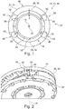
- the Fig. 5 shows one of the stator components 26 and two associated eccentric devices 36, 38 of the setting device 34. Arrows 58 indicate the setting options that can be implemented via the eccentric devices 36, 38.
- the Fig. 6 now shows the setting options that can be realized by rotating the eccentric devices 36, 38 in the same direction (arrows 60) in the case of FIG Fig. 5 stator component shown (dashed lines 62).
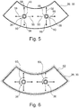
- the Fig. 7 now shows the setting options that can be realized by rotating the eccentric devices 36, 38 in opposite directions (arrows 60) in the case of FIG Fig. 5 stator component shown (dashed lines 62).
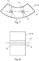
- FIG. 11 shows a section through the stator component 26 and one of the eccentric devices 36 of FIG Fig. 5 .
- the longitudinal axes of the eccentric sleeve or the eccentric sleeves arranged coaxially one behind the other (in Fig. 10 explicitly shown) 48 and the corresponding eccentric pins 50.
- the Fig. 9 shows the setting options of the Fig. 6 when the stator component 26 is supported on both sides via the eccentric devices 36, 38, i.e. by rotating the eccentric devices 36, 38 in the same direction (arrows 60 in Fig. 6 ), and
- the Fig. 10 shows the further setting options of the Fig. 7 when the stator component 26 is supported on both sides via the eccentric devices 36, 38, i.e. by rotating the eccentric devices 36, 38 in opposite directions (arrows 60 in Fig. 7 ).
- the eccentric device 36 shown has an eccentric pin 50 and two eccentric sleeves 48. It can be clearly seen that the longitudinal axes 66 of the eccentric pin 50 are tilted with respect to the longitudinal axes 64 of the eccentric sleeves 48 when the eccentric device 36 is set as shown. In this way, the axial alignment of the stator 16 or the stator components 26, 28 is tilted with respect to the alignment of the machine-fixed components 24, 24 ′ or the axis of rotation 16 of the rotor 14.
Landscapes
- Engineering & Computer Science (AREA)
- Power Engineering (AREA)
- Manufacturing & Machinery (AREA)
- Manufacture Of Motors, Generators (AREA)
Applications Claiming Priority (1)
| Application Number | Priority Date | Filing Date | Title |
|---|---|---|---|
| DE102020103231.5A DE102020103231A1 (de) | 2020-02-07 | 2020-02-07 | Einstelleinrichtung und Verfahren zum Einstellen eines radialen Luftspalt-Abstandes bei einer elektrischen Maschine |
Publications (1)
| Publication Number | Publication Date |
|---|---|
| EP3863164A1 true EP3863164A1 (fr) | 2021-08-11 |
Family
ID=74556709
Family Applications (1)
| Application Number | Title | Priority Date | Filing Date |
|---|---|---|---|
| EP21155404.3A Withdrawn EP3863164A1 (fr) | 2020-02-07 | 2021-02-05 | Dispositif de réglage et procédé de réglage d'une distance radiale de fente d'aération dans une machine électrique |
Country Status (2)
| Country | Link |
|---|---|
| EP (1) | EP3863164A1 (fr) |
| DE (1) | DE102020103231A1 (fr) |
Cited By (2)
| Publication number | Priority date | Publication date | Assignee | Title |
|---|---|---|---|---|
| CN115224900A (zh) * | 2022-07-13 | 2022-10-21 | 珠海格力电器股份有限公司 | 电机、空调器及其控制方法 |
| CN118409203A (zh) * | 2024-04-25 | 2024-07-30 | 华北电力大学(保定) | 一种基于轴套的永磁风力发电机气隙偏心模拟装置及方法 |
Citations (5)
| Publication number | Priority date | Publication date | Assignee | Title |
|---|---|---|---|---|
| US4444365A (en) * | 1981-11-25 | 1984-04-24 | Omac, Inc. | Double cam mounting assembly for mounting an aircraft wing to a fuselage to provide an adjustable angle of attack |
| EP2669531A1 (fr) * | 2012-06-01 | 2013-12-04 | Siemens Aktiengesellschaft | fixation des éléments de segment d'un stator |
| EP2960530A1 (fr) | 2014-06-27 | 2015-12-30 | Siemens Aktiengesellschaft | Procédé de montage pour une machine électrique dotée d'au moins deux segments de machine |
| WO2018113863A1 (fr) * | 2016-12-19 | 2018-06-28 | Vestas Wind Systems A/S | Dispositif de réglage à cames excentriques appariées |
| EP3352334A1 (fr) * | 2017-01-18 | 2018-07-25 | Siemens Aktiengesellschaft | Structure portante d'un noyau feuilleté d'un segment de stator |
Family Cites Families (2)
| Publication number | Priority date | Publication date | Assignee | Title |
|---|---|---|---|---|
| US7866027B2 (en) | 2005-12-09 | 2011-01-11 | Aisin Aw Co., Ltd. | Motor driving device manufacturing method |
| EP3691085A1 (fr) | 2019-01-29 | 2020-08-05 | Siemens Aktiengesellschaft | Fixation des segments de stator |
-
2020
- 2020-02-07 DE DE102020103231.5A patent/DE102020103231A1/de not_active Withdrawn
-
2021
- 2021-02-05 EP EP21155404.3A patent/EP3863164A1/fr not_active Withdrawn
Patent Citations (5)
| Publication number | Priority date | Publication date | Assignee | Title |
|---|---|---|---|---|
| US4444365A (en) * | 1981-11-25 | 1984-04-24 | Omac, Inc. | Double cam mounting assembly for mounting an aircraft wing to a fuselage to provide an adjustable angle of attack |
| EP2669531A1 (fr) * | 2012-06-01 | 2013-12-04 | Siemens Aktiengesellschaft | fixation des éléments de segment d'un stator |
| EP2960530A1 (fr) | 2014-06-27 | 2015-12-30 | Siemens Aktiengesellschaft | Procédé de montage pour une machine électrique dotée d'au moins deux segments de machine |
| WO2018113863A1 (fr) * | 2016-12-19 | 2018-06-28 | Vestas Wind Systems A/S | Dispositif de réglage à cames excentriques appariées |
| EP3352334A1 (fr) * | 2017-01-18 | 2018-07-25 | Siemens Aktiengesellschaft | Structure portante d'un noyau feuilleté d'un segment de stator |
Cited By (3)
| Publication number | Priority date | Publication date | Assignee | Title |
|---|---|---|---|---|
| CN115224900A (zh) * | 2022-07-13 | 2022-10-21 | 珠海格力电器股份有限公司 | 电机、空调器及其控制方法 |
| CN115224900B (zh) * | 2022-07-13 | 2025-11-18 | 珠海格力电器股份有限公司 | 电机、空调器及其控制方法 |
| CN118409203A (zh) * | 2024-04-25 | 2024-07-30 | 华北电力大学(保定) | 一种基于轴套的永磁风力发电机气隙偏心模拟装置及方法 |
Also Published As
| Publication number | Publication date |
|---|---|
| DE102020103231A1 (de) | 2021-08-12 |
Similar Documents
| Publication | Publication Date | Title |
|---|---|---|
| EP2655808B1 (fr) | Procédé pour retirer un corps de palier du rotor d'une turbine à gaz et prolongement d'arbre tubulaire | |
| DE112014007129T5 (de) | Statorkern für eine elektrische Rotationsmaschine, elektrische Rotationsmaschine und Verfahren zur Herstellung einer elektrischen Rotationsmaschine | |
| EP3480929B1 (fr) | Carter refroidi pour le stator d'entraînement direct | |
| EP1728306A2 (fr) | Ensemble stator de machine electrique | |
| EP2850719B1 (fr) | Ensemble stator pour machine electrique | |
| WO2018197192A1 (fr) | Machine électrique | |
| EP2960530A1 (fr) | Procédé de montage pour une machine électrique dotée d'au moins deux segments de machine | |
| EP3863164A1 (fr) | Dispositif de réglage et procédé de réglage d'une distance radiale de fente d'aération dans une machine électrique | |
| WO2014086633A2 (fr) | Machine dynamo-électrique munie d'un stator et/ou d'un rotor de conception segmentée | |
| EP1722460B1 (fr) | Machine électrique avec roulement à billes à précontrainte et procédé pour sa fabrication | |
| DE102021127747A1 (de) | Elektrische Maschinenanordnung | |
| EP3261221B1 (fr) | Rotor pour une machine électrique, machine électrique comprenant le rotor et procédé de fabrication du rotor | |
| EP3683933A1 (fr) | Assemblage d'un empilage de tôles sur un arbre | |
| EP3918694B1 (fr) | Fixation des segments de stator | |
| DE212018000250U1 (de) | Rotor für eine Elektromaschine | |
| EP3261224B1 (fr) | Machine électrique comprenant un rotor et procédé de fabrication de la machine électrique | |
| DE112018006990T5 (de) | Rotor, motor und verfahren zur herstellung eines rotors | |
| DE102013211476A1 (de) | Loslagersystem für eine elektrische Maschine | |
| EP3918693B1 (fr) | Fixation des segments de stator | |
| EP3035503A1 (fr) | Machine dynamoélectrique dotée d'un frein | |
| DE102013202031A1 (de) | Verfahren zum Aufbau einer elektrischen Maschine und elektrische Maschine | |
| EP2656484B1 (fr) | Machine a flux transversal | |
| EP4423892A1 (fr) | Moteur à flux axial fixé à un boîtier et doté d'une fonction de réglage | |
| DE102021209416A1 (de) | Verfahren zur Herstellung eines Rotors für eine elektrische Maschine, sowie Rotor für eine elektrische Maschine | |
| DE102018104074A1 (de) | Rotor, Rotorwelle und elektrische Maschine |
Legal Events
| Date | Code | Title | Description |
|---|---|---|---|
| PUAI | Public reference made under article 153(3) epc to a published international application that has entered the european phase |
Free format text: ORIGINAL CODE: 0009012 |
|
| STAA | Information on the status of an ep patent application or granted ep patent |
Free format text: STATUS: THE APPLICATION HAS BEEN PUBLISHED |
|
| AK | Designated contracting states |
Kind code of ref document: A1 Designated state(s): AL AT BE BG CH CY CZ DE DK EE ES FI FR GB GR HR HU IE IS IT LI LT LU LV MC MK MT NL NO PL PT RO RS SE SI SK SM TR |
|
| STAA | Information on the status of an ep patent application or granted ep patent |
Free format text: STATUS: THE APPLICATION IS DEEMED TO BE WITHDRAWN |
|
| 18D | Application deemed to be withdrawn |
Effective date: 20220212 |