EP3863231B1 - Réseau d'automatisation à communication basée sur paquets entre l'hôte et le client ainsi que procédé de fonctionnement d'un réseau d'automatisation - Google Patents
Réseau d'automatisation à communication basée sur paquets entre l'hôte et le client ainsi que procédé de fonctionnement d'un réseau d'automatisation Download PDFInfo
- Publication number
- EP3863231B1 EP3863231B1 EP20155402.9A EP20155402A EP3863231B1 EP 3863231 B1 EP3863231 B1 EP 3863231B1 EP 20155402 A EP20155402 A EP 20155402A EP 3863231 B1 EP3863231 B1 EP 3863231B1
- Authority
- EP
- European Patent Office
- Prior art keywords
- client
- client device
- host
- output value
- host device
- Prior art date
- Legal status (The legal status is an assumption and is not a legal conclusion. Google has not performed a legal analysis and makes no representation as to the accuracy of the status listed.)
- Active
Links
Images




Classifications
-
- H—ELECTRICITY
- H04—ELECTRIC COMMUNICATION TECHNIQUE
- H04L—TRANSMISSION OF DIGITAL INFORMATION, e.g. TELEGRAPHIC COMMUNICATION
- H04L67/00—Network arrangements or protocols for supporting network services or applications
- H04L67/01—Protocols
- H04L67/12—Protocols specially adapted for proprietary or special-purpose networking environments, e.g. medical networks, sensor networks, networks in vehicles or remote metering networks
- H04L67/125—Protocols specially adapted for proprietary or special-purpose networking environments, e.g. medical networks, sensor networks, networks in vehicles or remote metering networks involving control of end-device applications over a network
-
- H—ELECTRICITY
- H04—ELECTRIC COMMUNICATION TECHNIQUE
- H04L—TRANSMISSION OF DIGITAL INFORMATION, e.g. TELEGRAPHIC COMMUNICATION
- H04L12/00—Data switching networks
- H04L12/28—Data switching networks characterised by path configuration, e.g. LAN [Local Area Networks] or WAN [Wide Area Networks]
- H04L12/40—Bus networks
- H04L12/40006—Architecture of a communication node
- H04L12/40013—Details regarding a bus controller
-
- H—ELECTRICITY
- H04—ELECTRIC COMMUNICATION TECHNIQUE
- H04L—TRANSMISSION OF DIGITAL INFORMATION, e.g. TELEGRAPHIC COMMUNICATION
- H04L1/00—Arrangements for detecting or preventing errors in the information received
- H04L1/0001—Systems modifying transmission characteristics according to link quality, e.g. power backoff
- H04L1/0002—Systems modifying transmission characteristics according to link quality, e.g. power backoff by adapting the transmission rate
-
- H—ELECTRICITY
- H04—ELECTRIC COMMUNICATION TECHNIQUE
- H04L—TRANSMISSION OF DIGITAL INFORMATION, e.g. TELEGRAPHIC COMMUNICATION
- H04L1/00—Arrangements for detecting or preventing errors in the information received
- H04L1/12—Arrangements for detecting or preventing errors in the information received by using return channel
- H04L1/16—Arrangements for detecting or preventing errors in the information received by using return channel in which the return channel carries supervisory signals, e.g. repetition request signals
- H04L1/18—Automatic repetition systems, e.g. Van Duuren systems
- H04L1/1867—Arrangements specially adapted for the transmitter end
- H04L1/189—Transmission or retransmission of more than one copy of a message
-
- H—ELECTRICITY
- H04—ELECTRIC COMMUNICATION TECHNIQUE
- H04L—TRANSMISSION OF DIGITAL INFORMATION, e.g. TELEGRAPHIC COMMUNICATION
- H04L47/00—Traffic control in data switching networks
- H04L47/10—Flow control; Congestion control
- H04L47/24—Traffic characterised by specific attributes, e.g. priority or QoS
- H04L47/2483—Traffic characterised by specific attributes, e.g. priority or QoS involving identification of individual flows
-
- H—ELECTRICITY
- H04—ELECTRIC COMMUNICATION TECHNIQUE
- H04L—TRANSMISSION OF DIGITAL INFORMATION, e.g. TELEGRAPHIC COMMUNICATION
- H04L67/00—Network arrangements or protocols for supporting network services or applications
- H04L67/01—Protocols
- H04L67/12—Protocols specially adapted for proprietary or special-purpose networking environments, e.g. medical networks, sensor networks, networks in vehicles or remote metering networks
-
- H—ELECTRICITY
- H04—ELECTRIC COMMUNICATION TECHNIQUE
- H04L—TRANSMISSION OF DIGITAL INFORMATION, e.g. TELEGRAPHIC COMMUNICATION
- H04L69/00—Network arrangements, protocols or services independent of the application payload and not provided for in the other groups of this subclass
- H04L69/22—Parsing or analysis of headers
-
- Y—GENERAL TAGGING OF NEW TECHNOLOGICAL DEVELOPMENTS; GENERAL TAGGING OF CROSS-SECTIONAL TECHNOLOGIES SPANNING OVER SEVERAL SECTIONS OF THE IPC; TECHNICAL SUBJECTS COVERED BY FORMER USPC CROSS-REFERENCE ART COLLECTIONS [XRACs] AND DIGESTS
- Y02—TECHNOLOGIES OR APPLICATIONS FOR MITIGATION OR ADAPTATION AGAINST CLIMATE CHANGE
- Y02P—CLIMATE CHANGE MITIGATION TECHNOLOGIES IN THE PRODUCTION OR PROCESSING OF GOODS
- Y02P90/00—Enabling technologies with a potential contribution to greenhouse gas [GHG] emissions mitigation
- Y02P90/02—Total factory control, e.g. smart factories, flexible manufacturing systems [FMS] or integrated manufacturing systems [IMS]
Definitions
- the present invention relates to an automation network in which packet-based communication takes place between host and clients, a host and a client in this automation network and a method for operating such an automation network.
- Host-client systems are used in automation networks.
- the host often takes on complex control tasks involving the data of many clients.
- the input data of these clients is made available to the clients by the system that is controlled by the respective client.
- the systems controlled by the clients can be, for example, drones, individual industrial trucks in a warehouse or components of a complex production machine, such as motors for drives, pumps, switches, valves, etc.
- the input data mentioned can be data about the properties of the connected system describe switching states (e.g. of limit switches), motor speeds, speeds, temperatures, pressures, filling levels.
- This input data is processed in the host.
- the host provides data to the individual clients, which the client passes on to the connected system as output data, e.g. as switching outputs for controlling actuators, numerical setpoints for controlling motors, etc.
- Such a host-client architecture is chosen for two reasons.
- the capacity required to control complex systems (number of computing operations, memory, etc.) should be centrally provided in a data center or the cloud, for example on a large number of servers.
- the interplay of the (sub)systems controlled by the individual clients can be adequately taken into account.
- the clients in the on-site systems should be equipped with the simplest technology possible, i.e. with as few electronic components as possible and with low capacity. Therefore, control and regulation tasks are preferably carried out by a central instance instead of by the clients on site.
- Communication in such a host-client system can be wired, for example via Profibus, Profinet or Ethernet.
- wireless communication via radio is more suitable for controlling and regulating mobile systems.
- Packet-based standards of digital radio transmission such as the wireless versions of the connections mentioned above as well as 3G, 4G, 5G etc. are used for this.
- Packet-based communication is known from many areas. From the DE 11 2010 004 006 For example, a multiprocessor core with a chip-integrated network is known, which ensures that reliable communication is made possible by means of reliability requirements for the packets.
- an object of the present invention is to improve the operation of automation networks with packet-based communication between host and client.
- a method for operating an automation network which has a host device, at least one client device and a packet-based Communication connection between the host device and the client device, with the steps of generating and sending input value packets by the client device via the communication connection to the host device, generating and sending output value packets by the host device the communication link to the client device, and if the client device does not receive at least one seed packet via the communication link within a predetermined period of time, generating a replacement seed packet by the client device.
- the host is no longer able to process the control and/or regulation tasks that need to be completed quickly and to transmit corresponding output value packets to the client .
- Failure to receive a packet in a timely manner means that the client cannot provide the system connected to the automation network with the required output data.
- the client takes over the necessary generation of an output value packet, a so-called replacement output value packet itself. If the host does not receive an expected input value packet according to the specified Number of process cycles receives, it can send a signal to the client to generate a replacement output value packet itself.
- the method is expanded in that the replacement output value packets are generated by the client device as a function of at least one base operating point predetermined by the host device.
- Operating points are states specified by the properties of the system controlled by the client, which are also influenced by environmental parameters.
- the operating point is specified, for example, by the speed of the driven part and the torque of the electric motor.
- the operating point of an industrial truck is determined by internal parameters such as speed and steering angle and by external parameters such as the mass of the load being transported. For drones, for example, speed, location, altitude, wind speed and temperature are parameters that determine the operating point.
- the operating point is determined by the position of switches, valves, delivery rates and drive speeds.
- the operating point can also be formed by more complex parameters, such as the derivatives of simple parameters, as mentioned above as examples.
- the replacement output value packets are determined depending on the actual current operating point, i.e. the state in which the system is actually currently located, relative to an operating point referred to as the base operating point.
- This base operating point is determined in advance by the host.
- several basic operating points can also be determined. Such basic working points can be used for industrial trucks and drones or flights without load as well as trips or flights with low, medium or high load.
- the host can determine such a base operating point with predictable behavior.
- the host can then transmit further data to the client regardless of the normal processing of the current control and/or regulation task.
- This data includes, for example, the behavior for the control or regulation in the area around this basic operating point. This behavior may be based on a less complex algorithm than the algorithm running on the host. Then the same control quality will not be achieved as can be achieved with control on the host. Nevertheless, a failure or standstill of the control system in the event of delayed receipt of packages can be avoided.
- the client can then generate the output value packages itself, i.e. create replacement output value packages. This regulation by the client can also take place continuously in parallel with the generation of the output value packets on the host.
- one of the above methods is expanded in that the replacement output value packets are generated by the client device with the aid of a local processing module assigned to the client device.
- a module here is understood to mean an element that can be implemented in hardware, firmware or software. When implemented as software, this can be a program module, i.e. executable code.
- the less complex algorithm mentioned in the second embodiment, with which the client generates the replacement output value packets, can be implemented in a separate module on the client.
- a local processing module The client can be provided as a software program, as firmware or as its own hardware. Another algorithm that is independent of the operating point can also be used.
- the method according to the third embodiment is extended by transmitting parameters for the local processing module from the host device to the client device.
- Such parameters for the local processing module can, for example, be suitable parameters of a fixed algorithm that the local processing module processes.
- the algorithm in the local processing module can, for example, be based on a low-order system of equations that reproduces a quasi-steady state at the base operating point with sufficient accuracy.
- the local processing module may contain a state machine. Parameter sets are required to operate this state machine. The host has previously determined these parameter sets depending on the state of the system connected to the client, on the internal state of the host and/or depending on the states of other clients.
- the method according to the third or fourth embodiment is extended by transmitting the local processing module through the host device to the client device.
- the host transfers the local processing module completely to the client.
- the host creates the local processing module depending on the current state of the regulation or controller. This can be advantageously implemented in the form of flexible, app-based runtimes on the client.
- the method according to the second embodiment is carried out by determining the at least a predetermined base operating point extended by the host device at predetermined times.
- the host repeats the determination of base operating points that are likely to become valid in the near future at certain times, for example periodically.
- the times of determination or time intervals between successive determinations of operating points must be determined depending on the system to be monitored.
- the basic operating points can also be determined depending on input value packets of the respective client and/or other clients or depending on the state of the entire automation network. As already described in connection with the second embodiment, several possible basic operating points can of course be determined.
- the method according to one of the first to sixth embodiments is extended by the following step: accelerated generation of the output value packets by the host device until the host device has processed a current input value packet in a timely manner, in this case that at least one input value packet is not received within a predetermined period of time on the communication link in the direction from the client device to the host device; and continuing to generate the replacement output value packets by the client device until a current input value packet has been received on the host device and the host device generates the output value packets from this point onwards.
- the corresponding routine on the host carries out accelerated processing of the respective regulation or control processes.
- the process of the regulation or control that was omitted during the waiting time can be made up again until the internal state of the control or regulation for the current clock cycle has been established. From this point on, the control or regulation can work in normal operation again.
- the regulation or control can be taken over again by the host, and the regulation or control on the client can stop outputting the replacement output value packets to the connected system and instead output the output value packets received from the host.
- the method according to one of the first to seventh embodiments is expanded by the following steps: generating a manipulated variable for a controlled system, which receives a manipulated variable from the client device, from the output value packets by the client device and creating an input value -Packets from a measurement received from a measuring element by the client device.
- the method according to the eighth embodiment is expanded by the following step: generating the output value packets for determining the manipulated variable by the host device while processing the input value packets created by the client device from the measured variable.
- the method according to the fifth embodiment is extended by the following step: transmitting the local processing module through the host device to the client device via an alternative communication connection.
- the transmission of the local processing module does not have to occur with the same low latency as the transmission of the input value packets or the output value packets. Therefore, a communication connection can be established here via the air interface be used according to a standard with higher latency. If the client is not integrated into a mobile system or the mobile system containing the client is temporarily connected to the automation network via a plug-in connection, wired communication can also be used to transmit the local processing module.
- the method according to the fifth embodiment is extended by the following step: creation of the local processing module by the host device depending on a base operating point predetermined by the host device.
- the method according to one of the first to eleventh embodiments is extended by the following step: generating the replacement output value packets by the client device up to a time or location limit in the event that at least one packet is not present on the communication link is received within a specified period of time.
- the host When the host creates seed packets, it takes these parameters into account when creating the seed packets. However, if the client creates replacement seed packets, these parameters cannot be taken into account. In the latter case, disruptions can occur. These disruptions can be avoided by limiting the time in which the replacement output value packets are generated.
- an automation network which is set up to carry out a method according to one of the first to twelfth embodiments and which comprises a host device, at least one client device and a packet-based communication connection between the host device and the client device , wherein the client device is set up to generate and send input value packets to the host device via the communication connection and the host device is set up to generate and send output value packets to the client device via the communication connection, and the Client device is further set up to generate a replacement output value packet if the client device does not receive at least one output value packet within a predetermined period of time via the communication connection.
- a client device which is used to carry out a method is set up according to one of the first to twelfth embodiments.
- FIG. 1 an automation network 1 is shown schematically with a host 110, which is connected to clients 210, 220, 230, 240, ..., 290 via communication connections 910, 920, 930, 940, ..., 990.
- An example is in Fig. 2 Shown schematically that the host 110 receives information emitted by the client 210 via the communication connection 912 via an antenna 112 from its antenna 212 and itself transmits information to the client via the communication connection 911.
- the communication links 911 and 912 are part of the communication link 910 in Fig. 1 .
- this communication connection 915 there is a communication connection 915 between host and client, which is divided into communication connection 913, via which the host transmits information to the client, and communication connection 914, via which the host receives information from the client.
- This communication connection 915 is preferably also carried out via radio.
- the antenna 113 is present on the host and the antenna 213 is present on the client.
- Fig. 3 shows in detail the structure of the host 110, which is connected via the antenna 112 in the downlink direction via the communication connection 911 transmits output value packets 999 to the client and receives input value packets 998 from it in the uplink direction via the communication link 912.
- the communication connections 911 and 912 are parts of the communication connection 910 between host 110 and client 210.
- information can be exchanged between host 110 and client 210 via another communication connection 915.
- the automation module 310 which controls and regulates the process on the client 210.
- the information i.e. the input value packets from the other clients, is also taken into account.
- Further modules, not shown in the figures, for controlling and regulating the processes of the other clients 220 to 290 are also present on the host.
- Communication takes place via the communication module 319 via the connections 910 (consisting of the communication connections 911 and 912) and 915 (consisting of the communication connections 913 and 914) with the client 210. Further communication modules are provided for the remaining clients, which are not shown here .
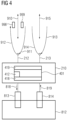
- Fig. 4 is a detailed representation of the client 210 exchanging the input value packets 998 and the output value packets 999 with the host using the antenna 212 over the communication links 911 and 912.
- the communication module 419 is included in the module 401 for the control and regulation of the client and the system connected to the client and controls communication with the host. Via a connection 818, the client 210 outputs its output signals using the communication module 418 to inputs 813 of the system 812 controlled by the automation network 1 via the client 210. This system 812 in turn sends signals using the communication connection 819 via outputs 814 to inputs of the client 210.
- the client 210 also has the communication connection 915 to the host. If necessary, the local processing module 412 generates output value packets 999 for output to the inputs 813 of the connected system 812.
- the local processing module 412 can be implemented as an app. Other possible embodiments include a realization of the module as hardware in the form of, for example, an ASIC or as an FPGA. Of course, the module can also be provided as software, firmware or hardware in a general-purpose processor or dedicated hardware.
- This local processing module 412 can be transmitted via the alternative communication link 915.
- This communication connection can be designed as a broadband radio connection with lower latency requirements, e.g. according to the 5G eMBB standard.
- Output value packages on the client do not necessarily have to be converted directly into outputs of the automation network.
- Output value packages can also be parameters for control processes.
- An example is the direction change instruction issued by the host, which is to be issued via the client to a means of transport as a connected system.
- the client can then implement this instruction differently, e.g. by issuing a command to control elements in the means of transport or by changing the speeds of individual drives of the means of transport, without details of the implementation being available to the client Host must be explicitly described in the initial value packages.
- the client can transmit data that it has received from the connected system to the host unchanged.
- the client can also evaluate and process data that it has received, for example from a means of transport as a connected system, before passing it on to the host.
- the client can convert speeds and data for the spatial orientation of the means of transport into input value packages that only contain the current one Speed and direction of movement of the means of transport included.
- Fig. 5 shows the normal timing of communication between system 812, client 210 and host 110 as it occurs in the prior art.
- the time arrows corresponding to these systems are marked with the reference numbers of the respective components.
- the input values 814 of the automation network i.e. outputs of the connected system 812
- the client determines the output values 813 and transmits them to the inputs of the system 812.
- a timer with the waiting time 995 is started on the client.
- Fig. 6 shows accordingly Fig. 5 the course of time when the transmission of the output value packets 999 is interrupted and/or only takes place with a delay. This can occur, for example, due to burst errors on the radio transmission link.
- a disruption in the immediate dispatch of the input value packets is indicated by wavy lines.
- the client After a predetermined waiting time 995 has elapsed, the client generates replacement output value packets 991 and outputs the corresponding output values 813 to the system 812. Not in Fig. 6
- the processes shown are that, on the one hand, the host sends repeat requests to the client if an expected input value packet is not present, and on the other hand, the client can send repeat requests to the host if an expected output value packet is not present.
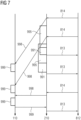
- Fig. 7 shows the history when input value packets 998 are transmitted to the client with a delay.
- the client takes over the generation of the replacement initial value packets 991 because it is not in time
- Corresponding packages are available from the host and outputs corresponding data 813 to the system.
- This delayed transmission of two input value packets to the host is represented by the inclination of the arrows symbolizing the transmission of the input value packets 998. If input value packets arrive at the host with a delay, the host evaluates the input value packets 998 in an accelerated manner.
- the host If, after processing all delayed processed input value packets 998, which are differentiated based on the timestamp, the host now has current output value packets 999 as a result of the accelerated processing, it outputs them to the client. These output value packets 999 are then forwarded back to the system by the client as outputs 813. This is in Fig. 7 shown at the bottom for the third input value package.
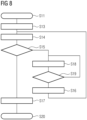
- Fig. 8 contains a flowchart for describing the method of the fifth embodiment.
- the method begins in step 511.
- the current actual operating point is determined in step S13.
- the host creates a new set of parameters for the local processing module for this operating point.
- step S15 it is checked whether the base operating point is still current, i.e. the actual operating point has not moved so far from the base operating point that the substitute control via the assigned processing module with the new parameterization can no longer deliver valid output values. If this is the case, i.e. if the basic operating point is still current, the new parameters are transmitted in step S17 to the client, which has its local processing module 412 (see. Fig. 4 ) is thus parameterized and executed.
- step S18 a new base operating point is created based on the actual operating point, including the associated local processing module 512 (see Fig. Fig. 3 ) created and checked whether the processing module for actual operating points enables a sufficiently high control quality in a sufficiently large area around the base operating point. Is this If this is not the case, this information is used to return to step S18 in order to generate a more suitable processing module. If the processing module is suitable for the control, it is transmitted to the client in step S16 and then returned to step 14 in order to now generate parameters for the current actual operating point based on the new processing module, which after successful verification in step S15 in step S17 can be transferred to the client. The method ends in step S20.
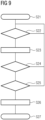
- Fig. 9 is a representation of the processes on the host for communication with the client. This procedure begins in step S21. In step S22 it is checked whether input value packets 998 were transmitted by the client. If this is not the case, the process returns to step S21. Otherwise, in step S23, the host generates output value packets 999 through suitable processing, for which data from other clients can also be used. If it is determined in step S24 that the time stamp of the input value packets is current, it is checked in step S25 whether There is currently no operation taking place via the local processing module 412 on the client. The host can then output the just calculated initial value package 999 to the client in step S26. If operation via the local processing module is detected in step S25, the system returns to step S22 to determine whether there are any further unprocessed input value packets. The method ends in step S27.
- the loss of input value packets is critical and should not actually occur, especially if the host has tasks such as logging or archiving the system states. Therefore, in the event of missing expected input value packets, the host sends requests to the client in which the host requests the client to repeat the transmission. Accordingly, the client must have a buffer in which the input value packets it sends are stored for a while to resend them in case of a repeat request from the host.
- step S31 the client transmits the current input data packet 998 to the host.
- step S33 the client transmits the current input data packet 998 to the host.
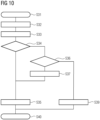
- step S34 the method checks in step S34 whether corresponding output value packets 999 are available from the host. If this is the case, this packet is used in step S35 as output data 813 (see. Fig. 4 ) passed to the system. If the check in step S34 was negative, it is checked in step S36 whether a local processing module 412 is ready for use. Furthermore, in this step S36 it is checked whether the system is within temporal or spatial limits for the operation of the local processing module 412.
- step S40 the local processing module 412 generates a seed packet 999 in step S37, which can then be output to the system in step S35. If no local processing module is ready or if the system has exceeded the specified time or location limits, the client executes an emergency program in step S39. Such an emergency program can, for example, cause an industrial truck to stop or a drone to land immediately. The method ends in step S40.
- Non-local means that it is an automation system that is external to the client that is directly connected to the system to be controlled or regulated.
- compact drones whose clients are limited in terms of system resources and have comparatively low computing power can controlled and regulated using complex processes that require a lot of resources.
- a further advantage of the present disclosure is the adaptability of the control or regulation system implemented in the client device, which has little complexity compared to the host, to the current situation, i.e. the actual operating point.
- radio channels can be used, for example in widely spaced frequency bands, with different modulation methods and/or with different spatial transmission modes.
- optical communication methods can also be used. Reduced sensitivity to interference can be achieved here.
Landscapes
- Engineering & Computer Science (AREA)
- Computer Networks & Wireless Communication (AREA)
- Signal Processing (AREA)
- Health & Medical Sciences (AREA)
- Computing Systems (AREA)
- General Health & Medical Sciences (AREA)
- Medical Informatics (AREA)
- Computer Security & Cryptography (AREA)
- Quality & Reliability (AREA)
- Data Exchanges In Wide-Area Networks (AREA)
- Small-Scale Networks (AREA)
- Mobile Radio Communication Systems (AREA)
Claims (15)
- Procédé d'exploitation d'un réseau d'automatisation (1) quiprésente au moins un dispositif client (210, 220, 230, 240, 290) qui commande un système (812) et reçoit des données d'entrée mises à disposition par le système (812) qui est commandé par le dispositif client,un dispositif hôte (110) pour l'exécution de tâches de commande complexes dans le réseau d'automatisation, etune liaison de communication par paquets (910) entre le dispositif hôte (110) et le dispositif client (210),avec les étapesde génération et d'envoi des données d'entrée dans des paquets de valeurs d'entrée (998) par le dispositif client (210) au dispositif hôte (110) via la liaison de communication (910),de génération et d'envoi des paquets de valeurs de sortie (999) incluant les données d'entrée du au moins un système client par le dispositif hôte (110) au dispositif client (210) via la liaison de communication (910), et,si le dispositif client (210) ne reçoit pas au moins un paquet de valeur de sortie (999) via la liaison de communication (910) dans un laps de temps prédéterminé, de génération par le dispositif client (210) d'un paquet de valeur de sortie de remplacement (991).
- Procédé selon la revendication 1,
caractérisé en ce que la génération des paquets de valeurs de sortie de remplacement (991) par le dispositif client (210) est effectuée en fonction d'au moins un point de fonctionnement de base prédéterminé par le dispositif hôte (110). - Procédé selon la revendication 1 ou 2,
caractérisé en ce que la génération des paquets de valeurs de sortie de remplacement (991) par le dispositif client (210) est effectuée à l'aide d'un module de traitement local (412) associé au dispositif client (210). - Procédé selon la revendication 3,
caractérisé par la communication de paramètres pour le module de traitement local (412) par le dispositif hôte (110) au dispositif client (210). - Procédé selon la revendication 3 ou 4,
caractérisé par la transmission du module de traitement local (512) par le dispositif hôte (110) au dispositif client (210). - Procédé selon la revendication 2,
caractérisé par la détermination de l'au moins un point de fonctionnement de base prédéterminé par ledit dispositif hôte (110) à des instants prédéterminés. - Procédé selon l'une quelconque des revendications 1 à 6,caractérisé par la génération accélérée des paquets de valeurs de sortie (999) par le dispositif hôte (110) jusqu'à ce que le dispositif hôte (110) ait traité à temps un paquet de valeurs d'entrée actuel (998), dans le cas où, sur la liaison de communication (910) dans le sens du dispositif client (210) vers le dispositif hôte (110), au moins un paquet de valeurs d'entrée (998) n'est pas reçu dans une période de temps prédéterminée ; etla génération continue des paquets de valeurs de sortie de remplacement (991) par le dispositif client (210) jusqu'à ce qu'un paquet de valeurs d'entrée actuel (998) ait été reçu sur le dispositif hôte (110) et que le dispositif hôte (110) génère les paquets de valeurs de sortie (999) à partir de ce moment.
- Procédé selon l'une quelconque des revendications 1 à 7,caractérisé par la génération par le dispositif client (210) à partir des paquets de valeurs de sortie (999) d'une grandeur de réglage (813) pour un système asservi (812), qui reçoit une grandeur de réglage (813) du dispositif client (210),la création par le dispositif client (210) de paquets de valeurs d'entrée (998) à partir d'une grandeur de mesure (814) reçue d'un élément de mesure (819).
- Procédé selon la revendication 8,
caractérisé par la génération des paquets de valeurs de sortie (999) pour la détermination de la grandeur de réglage (813) par le dispositif hôte (110) en traitant les paquets de valeurs d'entrée (998) créés par le dispositif client à partir de la grandeur de mesure (814). - Procédé selon la revendication 5,
caractérisé par la communication du module de traitement local (512) par le dispositif hôte (110) au dispositif client (210) via une liaison de communication alternative (915). - Procédé selon la revendication 5,
caractérisé par la création du module de traitement local (512) par le dispositif hôte (110) en fonction d'un point de fonctionnement de base prédéterminé par le dispositif hôte (110). - Procédé selon l'une quelconque des revendications 1 à 11,
caractérisé par la génération des paquets de valeur de sortie de remplacement (991) par le dispositif client (210) jusqu'à une limite de temps ou de lieu dans le cas où, sur la liaison de communication (910), au moins un paquet (998, 999) n'est pas reçu dans une période de temps prédéterminée. - Dispositif client (210) configuré pour commander un système (812), etrecevoir les données d'entrée mises à disposition par le système (812),pour générer et envoyer les données d'entrée dans des paquets de valeurs d'entrée (998) sur la liaison de communication (910) à un dispositif hôte (110), le dispositif hôte (110) étant configuré pour effectuer des tâches de commande complexes dans le réseau d'automatisation,et pour recevoir des paquets de valeurs de sortie (999) générés et envoyés par le dispositif hôte (110), incluant les données d'entrée, via la liaison de communication (910), et,configuré pour générer un paquet de valeur de sortie de remplacement (991) si le dispositif client (210) ne reçoit pas au moins un paquet de valeur de sortie (999) via la liaison de communication (910) dans une période de temps prédéterminée.
- Réseau d'automatisation (1) comprenant au moins un dispositif client (210, 220, 230, 240, 290) selon la revendication 13, etun dispositif hôte (110) pour l'exécution de tâches de commande complexes dans le réseau d'automatisation, etune liaison de communication par paquets (910) entre le dispositif hôte (110) et le dispositif client (210),dans lequel le dispositif client (210) est configuré pour générer et envoyer les données d'entrée dans des paquets de valeurs d'entrée (998) via la liaison de communication (910) au dispositif hôte (110),le dispositif hôte (110) est configuré pour générer et envoyer des paquets de valeurs de sortie (999) au dispositif client (210) via la liaison de communication (910), en incluant les données d'entrée du au moins un système client, et,le dispositif client (210) est en outre configuré pour générer un paquet de valeur de sortie de remplacement (991) si le dispositif client (210) ne reçoit pas au moins un paquet de valeur de sortie (999) via la liaison de communication (910) dans une période de temps prédéterminée.
- Réseau d'automatisation selon la revendication 14, caractérisé en ce qu'il est adapté pour mettre en œuvre un procédé présentant les caractéristiques selon l'une des revendications 2 à 12.
Priority Applications (3)
| Application Number | Priority Date | Filing Date | Title |
|---|---|---|---|
| EP20155402.9A EP3863231B1 (fr) | 2020-02-04 | 2020-02-04 | Réseau d'automatisation à communication basée sur paquets entre l'hôte et le client ainsi que procédé de fonctionnement d'un réseau d'automatisation |
| CN202110156990.8A CN113225367B (zh) | 2020-02-04 | 2021-02-03 | 主机和客户端之间基于包通信的自动化网络及其运行方法 |
| US17/166,314 US11509430B2 (en) | 2020-02-04 | 2021-02-03 | Method for operating an automation network having packet-based communication between a host and client |
Applications Claiming Priority (1)
| Application Number | Priority Date | Filing Date | Title |
|---|---|---|---|
| EP20155402.9A EP3863231B1 (fr) | 2020-02-04 | 2020-02-04 | Réseau d'automatisation à communication basée sur paquets entre l'hôte et le client ainsi que procédé de fonctionnement d'un réseau d'automatisation |
Publications (3)
| Publication Number | Publication Date |
|---|---|
| EP3863231A1 EP3863231A1 (fr) | 2021-08-11 |
| EP3863231C0 EP3863231C0 (fr) | 2023-11-15 |
| EP3863231B1 true EP3863231B1 (fr) | 2023-11-15 |
Family
ID=69468445
Family Applications (1)
| Application Number | Title | Priority Date | Filing Date |
|---|---|---|---|
| EP20155402.9A Active EP3863231B1 (fr) | 2020-02-04 | 2020-02-04 | Réseau d'automatisation à communication basée sur paquets entre l'hôte et le client ainsi que procédé de fonctionnement d'un réseau d'automatisation |
Country Status (3)
| Country | Link |
|---|---|
| US (1) | US11509430B2 (fr) |
| EP (1) | EP3863231B1 (fr) |
| CN (1) | CN113225367B (fr) |
Families Citing this family (1)
| Publication number | Priority date | Publication date | Assignee | Title |
|---|---|---|---|---|
| WO2021192314A1 (fr) * | 2020-03-27 | 2021-09-30 | 日本電気株式会社 | Dispositif de communication, procédé de commande de communication et support non transitoire lisible par ordinateur |
Family Cites Families (28)
| Publication number | Priority date | Publication date | Assignee | Title |
|---|---|---|---|---|
| US6549886B1 (en) * | 1999-11-03 | 2003-04-15 | Nokia Ip Inc. | System for lost packet recovery in voice over internet protocol based on time domain interpolation |
| US7274661B2 (en) * | 2001-09-17 | 2007-09-25 | Altera Corporation | Flow control method for quality streaming of audio/video/media over packet networks |
| CA2466380A1 (fr) * | 2001-11-21 | 2003-05-30 | Handshake Interactive Technologies Inc. | Commande en temps reel de materiel et de logiciel par le biais d'un reseau de communications |
| DE60223018T2 (de) * | 2002-08-20 | 2008-07-24 | Telefonaktiebolaget Lm Ericsson (Publ) | Verkehrsverwaltungsystem auf der Basis von Paketvermittlung mit Synchronisationseinrichtung zwischen Paketen und Objekten |
| DE10332360B4 (de) | 2003-07-17 | 2023-06-29 | Abb Schweiz Ag | Verfahren und System zur Verwaltung und Übertragung von Ereignissen einer zu überwachenden technischen Anlage in einer web-basierten Client-Server-Umgebung |
| EP1847071A4 (fr) * | 2005-01-26 | 2010-10-20 | Internet Broadcasting Corp B V | Multi-diffusion en couches et attribution exacte de largeur de bande et priorisation de paquets |
| US8018917B2 (en) * | 2005-11-21 | 2011-09-13 | Cisco Technology, Inc. | System and method for facilitating network performance analysis |
| US20090083391A1 (en) | 2007-09-20 | 2009-03-26 | Oh Yang Jen-Hsueh | Automatic control system with network gateway and method for operating the same |
| DE102007046326A1 (de) * | 2007-09-27 | 2009-04-09 | Delta Electronics, Inc. | Automatisches Steuerungssystem mit Netzwerk-Gateway sowie Verfahren zum Betreiben desselben |
| US8305904B1 (en) * | 2008-05-01 | 2012-11-06 | Sprint Communications Company L.P. | Method and system for verifying repairs in a telecommunication network |
| US8473818B2 (en) * | 2009-10-12 | 2013-06-25 | Empire Technology Development Llc | Reliable communications in on-chip networks |
| CN101692180B (zh) * | 2009-10-13 | 2012-01-04 | 江苏科技大学 | 遥操作机器人丢包补偿系统及其实现方法 |
| TWI383640B (zh) * | 2009-10-22 | 2013-01-21 | Wistron Corp | 利用網路傳輸檔案之方法與檔案傳輸系統 |
| US8537859B2 (en) * | 2010-02-26 | 2013-09-17 | Hewlett-Packard Development Company, L.P. | Reassembly of mini-packets in a buffer |
| CN101834469B (zh) * | 2010-04-16 | 2012-06-20 | 清华大学 | 一种变电站-调度中心两级分布式恢复控制方法 |
| CN102143137A (zh) * | 2010-09-10 | 2011-08-03 | 华为技术有限公司 | 媒体流发送及接收方法、装置和系统 |
| US10057014B2 (en) * | 2013-05-22 | 2018-08-21 | Google Llc | System and method for streaming data |
| DE102014201948B4 (de) * | 2014-02-04 | 2018-10-25 | Volkswagen Aktiengesellschaft | Verfahren zur Datenübertragung, Kommunikationsnetzwerk und Fahrzeug |
| US9923665B2 (en) * | 2014-06-06 | 2018-03-20 | Huawei Technologies Co., Ltd. | System and method for forward error correction |
| CN105763588B (zh) * | 2014-12-18 | 2020-02-04 | 阿里巴巴集团控股有限公司 | 一种关系网络数据的维护方法、离线服务器及实时服务器 |
| US10523985B2 (en) * | 2014-12-24 | 2019-12-31 | Activevideo Networks, Inc. | Managing deep and shallow buffers in a thin-client device of a digital media distribution network |
| CN205283595U (zh) * | 2015-08-17 | 2016-06-01 | 沈阳沈飞电子科技发展有限公司 | 物联网移动设备可控数据协议转换器 |
| CN105841701A (zh) * | 2016-06-15 | 2016-08-10 | 北京奇虎科技有限公司 | 离线导航方法、装置 |
| CN108646780B (zh) * | 2018-04-11 | 2023-09-01 | 广州亿航智能技术有限公司 | 载人无人机及其离线状态自动控制系统和方法及存储介质 |
| CN109104473B (zh) * | 2018-07-27 | 2022-11-08 | 深圳绿米联创科技有限公司 | 一种控制方法、控制装置、控制系统及网关 |
| CN110362104B (zh) * | 2019-06-06 | 2022-03-15 | 武汉易科空间信息技术股份有限公司 | 一种无人机导航过程中提升精度的方法及系统 |
| CN110244769B (zh) * | 2019-08-01 | 2024-04-26 | 极目(海南)智能育种装备有限公司 | 离线作业方法和装置 |
| CN110708222B (zh) * | 2019-10-14 | 2021-08-17 | 珠海格力电器股份有限公司 | 控制方法、装置、网关及存储介质 |
-
2020
- 2020-02-04 EP EP20155402.9A patent/EP3863231B1/fr active Active
-
2021
- 2021-02-03 US US17/166,314 patent/US11509430B2/en active Active
- 2021-02-03 CN CN202110156990.8A patent/CN113225367B/zh active Active
Also Published As
| Publication number | Publication date |
|---|---|
| CN113225367B (zh) | 2025-05-13 |
| US20210242973A1 (en) | 2021-08-05 |
| US11509430B2 (en) | 2022-11-22 |
| EP3863231A1 (fr) | 2021-08-11 |
| EP3863231C0 (fr) | 2023-11-15 |
| CN113225367A (zh) | 2021-08-06 |
Similar Documents
| Publication | Publication Date | Title |
|---|---|---|
| EP1516291B1 (fr) | Procede et dispositif destines a un service telematique concernant un vehicule | |
| EP2100411B1 (fr) | Procédé permettant de faire fonctionner un dispositif à bus de terrain compatible avec ethernet | |
| DE102020124484A1 (de) | Modulares prozesssteuerungssystem | |
| DE60012815T2 (de) | Numerisches Steuersystem | |
| EP2192458B2 (fr) | Dispositif de commande et procédé de gestion de l'énergie d'une installation d'automatisation industrielle | |
| DE112012000814B4 (de) | Datentransfervorrichtung | |
| DE112010005955B4 (de) | Steuerungssystem das während des Betriebs rekonfigurierbar ist, und Verfahren dafür | |
| EP1415208A1 (fr) | Procede et systeme de conduite de processus pour exploiter une installation technique | |
| DE10317390A1 (de) | Datenübertragungseinrichtung und elektronische Steuereinheit | |
| EP3673621B1 (fr) | Procédé de transmission de données entre un dispositif de commande central et une pluralité d'appareils décentralisés et dispositifs correspondants | |
| WO2015007297A1 (fr) | Unité de détection de données et système d'automatisation | |
| WO2015117749A1 (fr) | Module de bus de terrain, commande de machine et procédé de paramétrage d'un module de bus de terrain, notamment sécurisé | |
| EP3528064A1 (fr) | Système de commande et procédé associé de mise en marche, de commande et de surveillance pour des éléments d'alimentation électrique | |
| DE112018005805T5 (de) | Steuervorrichtung, Steuerverfahren und Programm | |
| EP3018542B1 (fr) | Installation d'automatisation ayant un mode pause à réduction de puissance | |
| EP3863231A1 (fr) | Réseau d'automatisation à communication basée sur un paquet entre l'hôte et le client ainsi que procédé de fonctionnement d'un réseau d'automatisation | |
| EP2662738A1 (fr) | Procédé et application de configuration dýun composant dans une installation dýautomatisation industrielle avec un appareil mobile | |
| EP3200034B1 (fr) | Accès aux données ou aux fonctions d'un automate programmable industriel à l'aide d'un service web | |
| EP3175307B1 (fr) | Production de valeurs de processus dans un système de processus | |
| WO2008074736A1 (fr) | Dispositif de commande pour au moins un moteur électrique et équipé d'un régulateur coopérant avec le dispositif de commande | |
| EP2090948B1 (fr) | Procédé de fonctionnement d'un système d'automatisation | |
| EP4558946B1 (fr) | Système de stockage et de préparation de commandes à flux de matériel optimisé | |
| EP4148514B1 (fr) | Système intégré de diagnostic pour stations de sortie de commande à distance basés sur la commande à mémoire programmable (sps) | |
| EP4068014B1 (fr) | Solution d'automatisation en nuage hautement disponible à temps de transmission optimisés | |
| DE102009036234B4 (de) | Kommunikationsgerät zur Datenkommunikation in einem Industrienetzwerk, Industrienetzwerk und Verfahren zur Steuerung der Datenkommunikation in einem Industrienetzwerk |
Legal Events
| Date | Code | Title | Description |
|---|---|---|---|
| PUAI | Public reference made under article 153(3) epc to a published international application that has entered the european phase |
Free format text: ORIGINAL CODE: 0009012 |
|
| STAA | Information on the status of an ep patent application or granted ep patent |
Free format text: STATUS: THE APPLICATION HAS BEEN PUBLISHED |
|
| AK | Designated contracting states |
Kind code of ref document: A1 Designated state(s): AL AT BE BG CH CY CZ DE DK EE ES FI FR GB GR HR HU IE IS IT LI LT LU LV MC MK MT NL NO PL PT RO RS SE SI SK SM TR |
|
| STAA | Information on the status of an ep patent application or granted ep patent |
Free format text: STATUS: REQUEST FOR EXAMINATION WAS MADE |
|
| 17P | Request for examination filed |
Effective date: 20220211 |
|
| RBV | Designated contracting states (corrected) |
Designated state(s): AL AT BE BG CH CY CZ DE DK EE ES FI FR GB GR HR HU IE IS IT LI LT LU LV MC MK MT NL NO PL PT RO RS SE SI SK SM TR |
|
| STAA | Information on the status of an ep patent application or granted ep patent |
Free format text: STATUS: EXAMINATION IS IN PROGRESS |
|
| 17Q | First examination report despatched |
Effective date: 20220502 |
|
| GRAP | Despatch of communication of intention to grant a patent |
Free format text: ORIGINAL CODE: EPIDOSNIGR1 |
|
| STAA | Information on the status of an ep patent application or granted ep patent |
Free format text: STATUS: GRANT OF PATENT IS INTENDED |
|
| INTG | Intention to grant announced |
Effective date: 20230629 |
|
| GRAS | Grant fee paid |
Free format text: ORIGINAL CODE: EPIDOSNIGR3 |
|
| GRAA | (expected) grant |
Free format text: ORIGINAL CODE: 0009210 |
|
| STAA | Information on the status of an ep patent application or granted ep patent |
Free format text: STATUS: THE PATENT HAS BEEN GRANTED |
|
| AK | Designated contracting states |
Kind code of ref document: B1 Designated state(s): AL AT BE BG CH CY CZ DE DK EE ES FI FR GB GR HR HU IE IS IT LI LT LU LV MC MK MT NL NO PL PT RO RS SE SI SK SM TR |
|
| REG | Reference to a national code |
Ref country code: CH Ref legal event code: EP Ref country code: GB Ref legal event code: FG4D Free format text: NOT ENGLISH |
|
| REG | Reference to a national code |
Ref country code: DE Ref legal event code: R096 Ref document number: 502020005994 Country of ref document: DE |
|
| REG | Reference to a national code |
Ref country code: IE Ref legal event code: FG4D Free format text: LANGUAGE OF EP DOCUMENT: GERMAN |
|
| U01 | Request for unitary effect filed |
Effective date: 20231117 |
|
| U07 | Unitary effect registered |
Designated state(s): AT BE BG DE DK EE FI FR IT LT LU LV MT NL PT SE SI Effective date: 20231123 |
|
| U20 | Renewal fee for the european patent with unitary effect paid |
Year of fee payment: 5 Effective date: 20240219 |
|
| PG25 | Lapsed in a contracting state [announced via postgrant information from national office to epo] |
Ref country code: GR Free format text: LAPSE BECAUSE OF FAILURE TO SUBMIT A TRANSLATION OF THE DESCRIPTION OR TO PAY THE FEE WITHIN THE PRESCRIBED TIME-LIMIT Effective date: 20240216 |
|
| PG25 | Lapsed in a contracting state [announced via postgrant information from national office to epo] |
Ref country code: IS Free format text: LAPSE BECAUSE OF FAILURE TO SUBMIT A TRANSLATION OF THE DESCRIPTION OR TO PAY THE FEE WITHIN THE PRESCRIBED TIME-LIMIT Effective date: 20240315 |
|
| PG25 | Lapsed in a contracting state [announced via postgrant information from national office to epo] |
Ref country code: ES Free format text: LAPSE BECAUSE OF FAILURE TO SUBMIT A TRANSLATION OF THE DESCRIPTION OR TO PAY THE FEE WITHIN THE PRESCRIBED TIME-LIMIT Effective date: 20231115 |
|
| PG25 | Lapsed in a contracting state [announced via postgrant information from national office to epo] |
Ref country code: IS Free format text: LAPSE BECAUSE OF FAILURE TO SUBMIT A TRANSLATION OF THE DESCRIPTION OR TO PAY THE FEE WITHIN THE PRESCRIBED TIME-LIMIT Effective date: 20240315 Ref country code: GR Free format text: LAPSE BECAUSE OF FAILURE TO SUBMIT A TRANSLATION OF THE DESCRIPTION OR TO PAY THE FEE WITHIN THE PRESCRIBED TIME-LIMIT Effective date: 20240216 Ref country code: ES Free format text: LAPSE BECAUSE OF FAILURE TO SUBMIT A TRANSLATION OF THE DESCRIPTION OR TO PAY THE FEE WITHIN THE PRESCRIBED TIME-LIMIT Effective date: 20231115 |
|
| PG25 | Lapsed in a contracting state [announced via postgrant information from national office to epo] |
Ref country code: RS Free format text: LAPSE BECAUSE OF FAILURE TO SUBMIT A TRANSLATION OF THE DESCRIPTION OR TO PAY THE FEE WITHIN THE PRESCRIBED TIME-LIMIT Effective date: 20231115 Ref country code: PL Free format text: LAPSE BECAUSE OF FAILURE TO SUBMIT A TRANSLATION OF THE DESCRIPTION OR TO PAY THE FEE WITHIN THE PRESCRIBED TIME-LIMIT Effective date: 20231115 Ref country code: NO Free format text: LAPSE BECAUSE OF FAILURE TO SUBMIT A TRANSLATION OF THE DESCRIPTION OR TO PAY THE FEE WITHIN THE PRESCRIBED TIME-LIMIT Effective date: 20240215 Ref country code: HR Free format text: LAPSE BECAUSE OF FAILURE TO SUBMIT A TRANSLATION OF THE DESCRIPTION OR TO PAY THE FEE WITHIN THE PRESCRIBED TIME-LIMIT Effective date: 20231115 |
|
| PG25 | Lapsed in a contracting state [announced via postgrant information from national office to epo] |
Ref country code: CZ Free format text: LAPSE BECAUSE OF FAILURE TO SUBMIT A TRANSLATION OF THE DESCRIPTION OR TO PAY THE FEE WITHIN THE PRESCRIBED TIME-LIMIT Effective date: 20231115 |
|
| PG25 | Lapsed in a contracting state [announced via postgrant information from national office to epo] |
Ref country code: SK Free format text: LAPSE BECAUSE OF FAILURE TO SUBMIT A TRANSLATION OF THE DESCRIPTION OR TO PAY THE FEE WITHIN THE PRESCRIBED TIME-LIMIT Effective date: 20231115 |
|
| PG25 | Lapsed in a contracting state [announced via postgrant information from national office to epo] |
Ref country code: SM Free format text: LAPSE BECAUSE OF FAILURE TO SUBMIT A TRANSLATION OF THE DESCRIPTION OR TO PAY THE FEE WITHIN THE PRESCRIBED TIME-LIMIT Effective date: 20231115 Ref country code: SK Free format text: LAPSE BECAUSE OF FAILURE TO SUBMIT A TRANSLATION OF THE DESCRIPTION OR TO PAY THE FEE WITHIN THE PRESCRIBED TIME-LIMIT Effective date: 20231115 Ref country code: RO Free format text: LAPSE BECAUSE OF FAILURE TO SUBMIT A TRANSLATION OF THE DESCRIPTION OR TO PAY THE FEE WITHIN THE PRESCRIBED TIME-LIMIT Effective date: 20231115 Ref country code: CZ Free format text: LAPSE BECAUSE OF FAILURE TO SUBMIT A TRANSLATION OF THE DESCRIPTION OR TO PAY THE FEE WITHIN THE PRESCRIBED TIME-LIMIT Effective date: 20231115 |
|
| REG | Reference to a national code |
Ref country code: DE Ref legal event code: R097 Ref document number: 502020005994 Country of ref document: DE |
|
| PLBE | No opposition filed within time limit |
Free format text: ORIGINAL CODE: 0009261 |
|
| STAA | Information on the status of an ep patent application or granted ep patent |
Free format text: STATUS: NO OPPOSITION FILED WITHIN TIME LIMIT |
|
| PG25 | Lapsed in a contracting state [announced via postgrant information from national office to epo] |
Ref country code: MC Free format text: LAPSE BECAUSE OF FAILURE TO SUBMIT A TRANSLATION OF THE DESCRIPTION OR TO PAY THE FEE WITHIN THE PRESCRIBED TIME-LIMIT Effective date: 20231115 |
|
| REG | Reference to a national code |
Ref country code: CH Ref legal event code: PL |
|
| PG25 | Lapsed in a contracting state [announced via postgrant information from national office to epo] |
Ref country code: CH Free format text: LAPSE BECAUSE OF NON-PAYMENT OF DUE FEES Effective date: 20240229 |
|
| 26N | No opposition filed |
Effective date: 20240819 |
|
| GBPC | Gb: european patent ceased through non-payment of renewal fee |
Effective date: 20240215 |
|
| PG25 | Lapsed in a contracting state [announced via postgrant information from national office to epo] |
Ref country code: CH Free format text: LAPSE BECAUSE OF NON-PAYMENT OF DUE FEES Effective date: 20240229 |
|
| PG25 | Lapsed in a contracting state [announced via postgrant information from national office to epo] |
Ref country code: GB Free format text: LAPSE BECAUSE OF NON-PAYMENT OF DUE FEES Effective date: 20240215 |
|
| PG25 | Lapsed in a contracting state [announced via postgrant information from national office to epo] |
Ref country code: IE Free format text: LAPSE BECAUSE OF NON-PAYMENT OF DUE FEES Effective date: 20240204 |
|
| PG25 | Lapsed in a contracting state [announced via postgrant information from national office to epo] |
Ref country code: IE Free format text: LAPSE BECAUSE OF NON-PAYMENT OF DUE FEES Effective date: 20240204 Ref country code: GB Free format text: LAPSE BECAUSE OF NON-PAYMENT OF DUE FEES Effective date: 20240215 |
|
| U20 | Renewal fee for the european patent with unitary effect paid |
Year of fee payment: 6 Effective date: 20250220 |
|
| PG25 | Lapsed in a contracting state [announced via postgrant information from national office to epo] |
Ref country code: CY Free format text: LAPSE BECAUSE OF FAILURE TO SUBMIT A TRANSLATION OF THE DESCRIPTION OR TO PAY THE FEE WITHIN THE PRESCRIBED TIME-LIMIT; INVALID AB INITIO Effective date: 20200204 |
|
| PG25 | Lapsed in a contracting state [announced via postgrant information from national office to epo] |
Ref country code: HU Free format text: LAPSE BECAUSE OF FAILURE TO SUBMIT A TRANSLATION OF THE DESCRIPTION OR TO PAY THE FEE WITHIN THE PRESCRIBED TIME-LIMIT; INVALID AB INITIO Effective date: 20200204 |
|
| PG25 | Lapsed in a contracting state [announced via postgrant information from national office to epo] |
Ref country code: TR Free format text: LAPSE BECAUSE OF FAILURE TO SUBMIT A TRANSLATION OF THE DESCRIPTION OR TO PAY THE FEE WITHIN THE PRESCRIBED TIME-LIMIT Effective date: 20231115 |
|
| U20 | Renewal fee for the european patent with unitary effect paid |
Year of fee payment: 7 Effective date: 20260219 |