EP3864314B1 - Scheibenbremse mit ausgeglichener verteilung der durch einen kolben auf mindestens einen bremsbelag aufgebrachten schubkräfte - Google Patents
Scheibenbremse mit ausgeglichener verteilung der durch einen kolben auf mindestens einen bremsbelag aufgebrachten schubkräfte Download PDFInfo
- Publication number
- EP3864314B1 EP3864314B1 EP19829289.8A EP19829289A EP3864314B1 EP 3864314 B1 EP3864314 B1 EP 3864314B1 EP 19829289 A EP19829289 A EP 19829289A EP 3864314 B1 EP3864314 B1 EP 3864314B1
- Authority
- EP
- European Patent Office
- Prior art keywords
- piston
- brake
- caliper
- pad
- brake pad
- Prior art date
- Legal status (The legal status is an assumption and is not a legal conclusion. Google has not performed a legal analysis and makes no representation as to the accuracy of the status listed.)
- Active
Links
Images




Classifications
-
- F—MECHANICAL ENGINEERING; LIGHTING; HEATING; WEAPONS; BLASTING
- F16—ENGINEERING ELEMENTS AND UNITS; GENERAL MEASURES FOR PRODUCING AND MAINTAINING EFFECTIVE FUNCTIONING OF MACHINES OR INSTALLATIONS; THERMAL INSULATION IN GENERAL
- F16D—COUPLINGS FOR TRANSMITTING ROTATION; CLUTCHES; BRAKES
- F16D65/00—Parts or details
- F16D65/14—Actuating mechanisms for brakes; Means for initiating operation at a predetermined position
- F16D65/16—Actuating mechanisms for brakes; Means for initiating operation at a predetermined position arranged in or on the brake
- F16D65/18—Actuating mechanisms for brakes; Means for initiating operation at a predetermined position arranged in or on the brake adapted for drawing members together, e.g. for disc brakes
-
- F—MECHANICAL ENGINEERING; LIGHTING; HEATING; WEAPONS; BLASTING
- F16—ENGINEERING ELEMENTS AND UNITS; GENERAL MEASURES FOR PRODUCING AND MAINTAINING EFFECTIVE FUNCTIONING OF MACHINES OR INSTALLATIONS; THERMAL INSULATION IN GENERAL
- F16D—COUPLINGS FOR TRANSMITTING ROTATION; CLUTCHES; BRAKES
- F16D65/00—Parts or details
- F16D65/02—Braking members; Mounting thereof
- F16D65/04—Bands, shoes or pads; Pivots or supporting members therefor
- F16D65/092—Bands, shoes or pads; Pivots or supporting members therefor for axially-engaging brakes, e.g. disc brakes
-
- F—MECHANICAL ENGINEERING; LIGHTING; HEATING; WEAPONS; BLASTING
- F16—ENGINEERING ELEMENTS AND UNITS; GENERAL MEASURES FOR PRODUCING AND MAINTAINING EFFECTIVE FUNCTIONING OF MACHINES OR INSTALLATIONS; THERMAL INSULATION IN GENERAL
- F16D—COUPLINGS FOR TRANSMITTING ROTATION; CLUTCHES; BRAKES
- F16D55/00—Brakes with substantially-radial braking surfaces pressed together in axial direction, e.g. disc brakes
- F16D55/02—Brakes with substantially-radial braking surfaces pressed together in axial direction, e.g. disc brakes with axially-movable discs or pads pressed against axially-located rotating members
- F16D55/22—Brakes with substantially-radial braking surfaces pressed together in axial direction, e.g. disc brakes with axially-movable discs or pads pressed against axially-located rotating members by clamping an axially-located rotating disc between movable braking members, e.g. movable brake discs or brake pads
- F16D55/224—Brakes with substantially-radial braking surfaces pressed together in axial direction, e.g. disc brakes with axially-movable discs or pads pressed against axially-located rotating members by clamping an axially-located rotating disc between movable braking members, e.g. movable brake discs or brake pads with a common actuating member for the braking members
- F16D55/225—Brakes with substantially-radial braking surfaces pressed together in axial direction, e.g. disc brakes with axially-movable discs or pads pressed against axially-located rotating members by clamping an axially-located rotating disc between movable braking members, e.g. movable brake discs or brake pads with a common actuating member for the braking members the braking members being brake pads
- F16D55/226—Brakes with substantially-radial braking surfaces pressed together in axial direction, e.g. disc brakes with axially-movable discs or pads pressed against axially-located rotating members by clamping an axially-located rotating disc between movable braking members, e.g. movable brake discs or brake pads with a common actuating member for the braking members the braking members being brake pads in which the common actuating member is moved axially, e.g. floating caliper disc brakes
-
- F—MECHANICAL ENGINEERING; LIGHTING; HEATING; WEAPONS; BLASTING
- F16—ENGINEERING ELEMENTS AND UNITS; GENERAL MEASURES FOR PRODUCING AND MAINTAINING EFFECTIVE FUNCTIONING OF MACHINES OR INSTALLATIONS; THERMAL INSULATION IN GENERAL
- F16D—COUPLINGS FOR TRANSMITTING ROTATION; CLUTCHES; BRAKES
- F16D55/00—Brakes with substantially-radial braking surfaces pressed together in axial direction, e.g. disc brakes
- F16D55/02—Brakes with substantially-radial braking surfaces pressed together in axial direction, e.g. disc brakes with axially-movable discs or pads pressed against axially-located rotating members
- F16D55/22—Brakes with substantially-radial braking surfaces pressed together in axial direction, e.g. disc brakes with axially-movable discs or pads pressed against axially-located rotating members by clamping an axially-located rotating disc between movable braking members, e.g. movable brake discs or brake pads
- F16D55/224—Brakes with substantially-radial braking surfaces pressed together in axial direction, e.g. disc brakes with axially-movable discs or pads pressed against axially-located rotating members by clamping an axially-located rotating disc between movable braking members, e.g. movable brake discs or brake pads with a common actuating member for the braking members
- F16D55/225—Brakes with substantially-radial braking surfaces pressed together in axial direction, e.g. disc brakes with axially-movable discs or pads pressed against axially-located rotating members by clamping an axially-located rotating disc between movable braking members, e.g. movable brake discs or brake pads with a common actuating member for the braking members the braking members being brake pads
- F16D55/226—Brakes with substantially-radial braking surfaces pressed together in axial direction, e.g. disc brakes with axially-movable discs or pads pressed against axially-located rotating members by clamping an axially-located rotating disc between movable braking members, e.g. movable brake discs or brake pads with a common actuating member for the braking members the braking members being brake pads in which the common actuating member is moved axially, e.g. floating caliper disc brakes
- F16D55/2262—Brakes with substantially-radial braking surfaces pressed together in axial direction, e.g. disc brakes with axially-movable discs or pads pressed against axially-located rotating members by clamping an axially-located rotating disc between movable braking members, e.g. movable brake discs or brake pads with a common actuating member for the braking members the braking members being brake pads in which the common actuating member is moved axially, e.g. floating caliper disc brakes the axial movement being guided by open sliding surfaces, e.g. grooves
-
- F—MECHANICAL ENGINEERING; LIGHTING; HEATING; WEAPONS; BLASTING
- F16—ENGINEERING ELEMENTS AND UNITS; GENERAL MEASURES FOR PRODUCING AND MAINTAINING EFFECTIVE FUNCTIONING OF MACHINES OR INSTALLATIONS; THERMAL INSULATION IN GENERAL
- F16D—COUPLINGS FOR TRANSMITTING ROTATION; CLUTCHES; BRAKES
- F16D55/00—Brakes with substantially-radial braking surfaces pressed together in axial direction, e.g. disc brakes
- F16D55/02—Brakes with substantially-radial braking surfaces pressed together in axial direction, e.g. disc brakes with axially-movable discs or pads pressed against axially-located rotating members
- F16D55/22—Brakes with substantially-radial braking surfaces pressed together in axial direction, e.g. disc brakes with axially-movable discs or pads pressed against axially-located rotating members by clamping an axially-located rotating disc between movable braking members, e.g. movable brake discs or brake pads
- F16D55/224—Brakes with substantially-radial braking surfaces pressed together in axial direction, e.g. disc brakes with axially-movable discs or pads pressed against axially-located rotating members by clamping an axially-located rotating disc between movable braking members, e.g. movable brake discs or brake pads with a common actuating member for the braking members
- F16D55/225—Brakes with substantially-radial braking surfaces pressed together in axial direction, e.g. disc brakes with axially-movable discs or pads pressed against axially-located rotating members by clamping an axially-located rotating disc between movable braking members, e.g. movable brake discs or brake pads with a common actuating member for the braking members the braking members being brake pads
- F16D55/226—Brakes with substantially-radial braking surfaces pressed together in axial direction, e.g. disc brakes with axially-movable discs or pads pressed against axially-located rotating members by clamping an axially-located rotating disc between movable braking members, e.g. movable brake discs or brake pads with a common actuating member for the braking members the braking members being brake pads in which the common actuating member is moved axially, e.g. floating caliper disc brakes
- F16D55/2265—Brakes with substantially-radial braking surfaces pressed together in axial direction, e.g. disc brakes with axially-movable discs or pads pressed against axially-located rotating members by clamping an axially-located rotating disc between movable braking members, e.g. movable brake discs or brake pads with a common actuating member for the braking members the braking members being brake pads in which the common actuating member is moved axially, e.g. floating caliper disc brakes the axial movement being guided by one or more pins engaging bores in the brake support or the brake housing
- F16D55/227—Brakes with substantially-radial braking surfaces pressed together in axial direction, e.g. disc brakes with axially-movable discs or pads pressed against axially-located rotating members by clamping an axially-located rotating disc between movable braking members, e.g. movable brake discs or brake pads with a common actuating member for the braking members the braking members being brake pads in which the common actuating member is moved axially, e.g. floating caliper disc brakes the axial movement being guided by one or more pins engaging bores in the brake support or the brake housing by two or more pins
-
- F—MECHANICAL ENGINEERING; LIGHTING; HEATING; WEAPONS; BLASTING
- F16—ENGINEERING ELEMENTS AND UNITS; GENERAL MEASURES FOR PRODUCING AND MAINTAINING EFFECTIVE FUNCTIONING OF MACHINES OR INSTALLATIONS; THERMAL INSULATION IN GENERAL
- F16D—COUPLINGS FOR TRANSMITTING ROTATION; CLUTCHES; BRAKES
- F16D65/00—Parts or details
- F16D65/005—Components of axially engaging brakes not otherwise provided for
- F16D65/0068—Brake calipers
-
- F—MECHANICAL ENGINEERING; LIGHTING; HEATING; WEAPONS; BLASTING
- F16—ENGINEERING ELEMENTS AND UNITS; GENERAL MEASURES FOR PRODUCING AND MAINTAINING EFFECTIVE FUNCTIONING OF MACHINES OR INSTALLATIONS; THERMAL INSULATION IN GENERAL
- F16D—COUPLINGS FOR TRANSMITTING ROTATION; CLUTCHES; BRAKES
- F16D65/00—Parts or details
- F16D65/02—Braking members; Mounting thereof
- F16D65/04—Bands, shoes or pads; Pivots or supporting members therefor
- F16D65/092—Bands, shoes or pads; Pivots or supporting members therefor for axially-engaging brakes, e.g. disc brakes
- F16D65/095—Pivots or supporting members therefor
-
- F—MECHANICAL ENGINEERING; LIGHTING; HEATING; WEAPONS; BLASTING
- F16—ENGINEERING ELEMENTS AND UNITS; GENERAL MEASURES FOR PRODUCING AND MAINTAINING EFFECTIVE FUNCTIONING OF MACHINES OR INSTALLATIONS; THERMAL INSULATION IN GENERAL
- F16D—COUPLINGS FOR TRANSMITTING ROTATION; CLUTCHES; BRAKES
- F16D65/00—Parts or details
- F16D65/02—Braking members; Mounting thereof
- F16D65/04—Bands, shoes or pads; Pivots or supporting members therefor
- F16D65/092—Bands, shoes or pads; Pivots or supporting members therefor for axially-engaging brakes, e.g. disc brakes
- F16D65/095—Pivots or supporting members therefor
- F16D65/097—Resilient means interposed between pads and supporting members or other brake parts
-
- F—MECHANICAL ENGINEERING; LIGHTING; HEATING; WEAPONS; BLASTING
- F16—ENGINEERING ELEMENTS AND UNITS; GENERAL MEASURES FOR PRODUCING AND MAINTAINING EFFECTIVE FUNCTIONING OF MACHINES OR INSTALLATIONS; THERMAL INSULATION IN GENERAL
- F16D—COUPLINGS FOR TRANSMITTING ROTATION; CLUTCHES; BRAKES
- F16D65/00—Parts or details
- F16D65/02—Braking members; Mounting thereof
- F16D65/04—Bands, shoes or pads; Pivots or supporting members therefor
- F16D65/092—Bands, shoes or pads; Pivots or supporting members therefor for axially-engaging brakes, e.g. disc brakes
- F16D65/095—Pivots or supporting members therefor
- F16D65/097—Resilient means interposed between pads and supporting members or other brake parts
- F16D65/0971—Resilient means interposed between pads and supporting members or other brake parts transmitting brake actuation force, e.g. elements interposed between brake piston and pad
-
- F—MECHANICAL ENGINEERING; LIGHTING; HEATING; WEAPONS; BLASTING
- F16—ENGINEERING ELEMENTS AND UNITS; GENERAL MEASURES FOR PRODUCING AND MAINTAINING EFFECTIVE FUNCTIONING OF MACHINES OR INSTALLATIONS; THERMAL INSULATION IN GENERAL
- F16D—COUPLINGS FOR TRANSMITTING ROTATION; CLUTCHES; BRAKES
- F16D55/00—Brakes with substantially-radial braking surfaces pressed together in axial direction, e.g. disc brakes
- F16D2055/0004—Parts or details of disc brakes
- F16D2055/0016—Brake calipers
-
- F—MECHANICAL ENGINEERING; LIGHTING; HEATING; WEAPONS; BLASTING
- F16—ENGINEERING ELEMENTS AND UNITS; GENERAL MEASURES FOR PRODUCING AND MAINTAINING EFFECTIVE FUNCTIONING OF MACHINES OR INSTALLATIONS; THERMAL INSULATION IN GENERAL
- F16D—COUPLINGS FOR TRANSMITTING ROTATION; CLUTCHES; BRAKES
- F16D2121/00—Type of actuator operation force
- F16D2121/02—Fluid pressure
- F16D2121/04—Fluid pressure acting on a piston-type actuator, e.g. for liquid pressure
-
- F—MECHANICAL ENGINEERING; LIGHTING; HEATING; WEAPONS; BLASTING
- F16—ENGINEERING ELEMENTS AND UNITS; GENERAL MEASURES FOR PRODUCING AND MAINTAINING EFFECTIVE FUNCTIONING OF MACHINES OR INSTALLATIONS; THERMAL INSULATION IN GENERAL
- F16D—COUPLINGS FOR TRANSMITTING ROTATION; CLUTCHES; BRAKES
- F16D2125/00—Components of actuators
- F16D2125/18—Mechanical mechanisms
- F16D2125/58—Mechanical mechanisms transmitting linear movement
- F16D2125/587—Articulation, e.g. ball-socket
-
- F—MECHANICAL ENGINEERING; LIGHTING; HEATING; WEAPONS; BLASTING
- F16—ENGINEERING ELEMENTS AND UNITS; GENERAL MEASURES FOR PRODUCING AND MAINTAINING EFFECTIVE FUNCTIONING OF MACHINES OR INSTALLATIONS; THERMAL INSULATION IN GENERAL
- F16D—COUPLINGS FOR TRANSMITTING ROTATION; CLUTCHES; BRAKES
- F16D65/00—Parts or details
- F16D65/02—Braking members; Mounting thereof
- F16D65/04—Bands, shoes or pads; Pivots or supporting members therefor
- F16D65/092—Bands, shoes or pads; Pivots or supporting members therefor for axially-engaging brakes, e.g. disc brakes
- F16D65/095—Pivots or supporting members therefor
- F16D65/097—Resilient means interposed between pads and supporting members or other brake parts
- F16D65/0973—Resilient means interposed between pads and supporting members or other brake parts not subjected to brake forces
- F16D65/0979—Resilient means interposed between pads and supporting members or other brake parts not subjected to brake forces acting on the rear side of the pad or an element affixed thereto, e.g. spring clips securing the pad to the brake piston or caliper
Definitions
- the present invention relates to the field of disc brakes, in particular disc brakes with at least part electrical actuation.
- An example of a disc brake comprises a yoke intended to be fixed to a steering knuckle of a motor vehicle, a caliper mounted floating relative to the yoke, two brake pads intended to come into contact with a brake disc fixed in rotation on a wheel.
- the caliper comprises a piston which can be moved under the action of a pressurized fluid to apply one of the pads against one face of the brake disc. By reaction, the caliper slides and applies the other pad against the other face of the brake disc.
- the parking brake serves to immobilize the vehicle when stationary to prevent it from moving unexpectedly. It also meets the legal requirement for a second braking system independent of the service braking system, usually hydraulic.
- disc brakes equipped with an electromechanical parking brake braking during the driving phase being obtained by hydraulic actuation, comprising a device which, under the action of an electric motor, allows the piston to be moved in order to apply the brake pads against the disc.
- the device is, for example, a worm screw and is housed in the piston.
- a button located in the passenger compartment allows the parking brake to be activated.
- twin-piston disc brakes i.e. comprising two pistons which are actuated simultaneously to apply the pads against the disc.
- twin-piston disc brakes i.e. comprising two pistons which are actuated simultaneously to apply the pads against the disc.
- This type of disc brake is used, for example, in so-called high-powered sports cars or in sports utility vehicles (SUVs).
- SUVs sports utility vehicles
- US 2018/298963 A1 discloses a disc brake known from the prior art comprising a shoe between a piston and a brake pad.
- a further aim of the present invention is to provide a disc brake capable of developing high braking power with reduced mass and/or size compared to disc brakes of the state of the art developing equivalent braking power.
- a disc brake comprising a caliper, a yoke, at least one brake pad, at least one piston and an electromechanical actuator configured to move the piston so as to apply the brake pad against the disc.
- the disc brake also comprises an intercalary device according to claim 1 mounted between the nose of the piston and the pad allowing the thrust force of said piston to be distributed in a balanced manner on the brake pad.
- the intermediate device is of the rocker type ensuring a balanced distribution of the piston thrust force in at least two zones of the pad.
- the brake pad is that of a twin-piston disc brake and the areas are those on which the two pistons of a conventional twin-piston disc brake would normally press on the pad.
- the spacer device simulates the application of the thrust forces exerted by at least two pistons, so that the pad sees the support of at least two pistons.
- the invention makes it possible to exert the thrust forces of a twin-piston brake from a single piston advantageously driven by a single electric actuator without modifying the mechanical strength of the brake, because the part that supports the two pistons in a twin-piston brake does not participate in the mechanical strength of the brake.
- the weight saving is significant because this part is generally made of cast iron.
- the intermediate device with a rocker arm comprises several parts articulated together by ball joints.
- the intermediate device is advantageously secured to the piston by a ball joint.
- the intermediate device is guided in the yoke, like the brake plate, to support the braking torque and so that this torque is not applied to the piston at the center of thrust.
- it comprises two ears mounted in the grooves guiding the brake pad.
- the intercalary device comprising means for securing with the piston in the axial direction.
- the securing means are such that they are activated automatically when the caliper is closed on the pads.
- the disc brake advantageously comprises an electromechanical actuator of a single-piston brake, which makes it possible to produce a twin-piston disc brake with electromechanical actuation without having to redevelop an actuator. electromechanical specific to the movement of two pistons. In addition, the mass and size are reduced.
- the intercalary device is attached between the piston and the inner brake pad.
- the spacer device is attached to the inner brake pad, e.g. it is a single piece, the device can then be replaced with the worn pad.
- the present invention then relates to a disc brake comprising a yoke, at least one first brake pad slidably mounted in the yoke, said first brake pad comprising a pad support and a friction material, a caliper comprising at least one piston slidably mounted in the caliper so as to move the first brake pad relative to the yoke, at least one actuator configured to axially move the piston, and an interposed device according to claim 1 interposed between the piston and the first brake pad forming a lever so as to distribute the thrust force exerted by the piston over at least two zones of the first brake pad, at least partly distinct from the projection of the piston on the first brake pad.
- the intermediate device comprises a first part and at least two second parts and a ball joint between the first part and each second part.
- the second parts of the intermediate device advantageously each comprise a branch, a free end of which is mounted in one of said grooves.
- the brake comprises a ball joint between the first part and the piston.
- the ball joint between the first part and the piston comprises a first element secured to the piston and a second element secured to the first part, the first element or the second element penetrating into the second element or the first element respectively, so as to form a ball joint between the piston and the spacer device and ensure axial connection between the piston and the spacer device at least when the piston enters the caliper.
- the at least two zones are preferably offset from each other transversely.
- the at least two zones have a circular shape.
- the ball joints are for example arranged so that their projection on the first brake pad is at the center of said zones.
- the disc brake may include a second brake pad, a first pin and a second pin allowing sliding between the caliper and the yoke, at least the second pin allowing rotation of the caliper about the first pin.
- the caliper may also include an arch and a nose intended to apply a force to the second brake pad.
- one of the first and second elements comprises a housing opening towards the arch of the caliper and a window opening towards the second element or the first element respectively, and the second or the first element comprises a head and a rod, the head being sized to penetrate into the housing, and to form an axial stop between the piston and the intermediate device.
- the intercalary device is made of the same material as the piston.
- the caliper comprises a piston and an actuator of said piston and the yoke and the first brake pad have the dimensions of a brake pad of a twin-piston disc brake.
- the actuator is an electromechanical actuator.
- the present invention also relates to an interposing device intended to be interposed between a piston of a disc brake and an inner brake pad support, comprising a first part and at least two second parts, a ball joint between the first part and each second part. Said first part is configured to be secured to the piston by a ball joint and said second parts parts are intended to come into contact with a brake pad support.
- each second part comprises a surface for transmitting a thrust force to the pad support and a portion intended to cooperate with the yoke to ensure its guidance in the yoke.
- the present invention also relates to a brake pad comprising a pad support and a friction material and an interposed device according to the invention, fixed to a face of the pad support opposite that carrying the friction material.
- the brake is fully electromechanically actuated, the electromechanical actuator actuated by an electric motor ensures both braking during the driving phase (service brake) and parking braking (parking brake).
- the disc brake comprises a hydraulic actuator.
- the axial direction is parallel to the disk axis and the transverse direction is orthogonal to the disk axis.
- the upstream-downstream direction is considered in the direction of axial movement of the piston during braking.
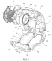
- the disc brake 10 comprises a caliper 12 comprising a rear housing 14 in which a brake piston 16 is mounted to slide axially along the axis X.
- the disc brake also includes a yoke 15 intended to be fixed on the steering knuckle of a wheel.
- the yoke 15 supports the brake shoes or brake pads P1 and P2.
- the disc brake has two columns C1 and C2 allowing the caliper to slide relative to the yoke.
- One of the columns C2 allows the brake to be opened by pivoting the caliper around the other column C1 and the brake pads to be replaced.
- the brake pads have lugs, only the lugs P2.1, P2.1 of the outer plate P2 are visible.
- the lugs extend laterally outwards and cooperate with grooves 19 or grooves carried by the yoke so as to ensure the axial guidance of the pads relative to the disc.
- springs R1, R2 are mounted in the grooves and receive the lugs. The springs facilitate the sliding of the pads and can provide an axial guidance and return function, or even a play-compensating function.
- the disc brake 10 comprises, at the rear, a motor-reducer group or electromechanical actuator 17 of which a housing 18 is shown which houses an electric motor and a reduction mechanism, for example with epicyclic gears.
- the housing 18 is attached and fixed to a rear face of the caliper 12 against which the housing 18 is fixed, the fixing being here ensured by screws 22.
- the rear housing 14 of the caliper 12 delimits a cavity in which the piston 16 is mounted sliding axially in a sealed manner in both directions, along the axis X.
- the brake piston 16 is a part in the general shape of a disc, a downstream face 26 of which is intended to cooperate with an associated disc brake pad P1, called the inner pad or inner pad.
- the geared motor is for example close or similar to the geared motor described in the document FR3024516 .
- the piston has a screw 29 (projecting from its upstream face 27 opposite the face 26) figure 6 And 7 ) intended to cooperate with a nut (not shown) intended to be driven in rotation by an electric motor.
- the caliper 12 is of the sliding type.
- the caliper comprises a caliper nose 30 connected to the housing 18 by an arch 32 intended to straddle the brake disc D (shown in dotted lines on the figure 4 ).
- Nose 30 is located axially downstream of the outer pad considering the direction of movement of the inner pad P1.
- the nose 30 is intended to exert a thrust force on the outer pad P2 in the direction of the disk in the following manner.
- the inner pad P1 is moved by the piston 16 to come into contact with one face of the disc and the outer pad P2 is moved towards the other face of the disc by movement of the caliper by reaction, due to the contact between the inner pad and the brake disc.
- the dimensions of the disk D intended to be braked by the disk brake, of the brake pads P1, P2, of the yoke 15 supporting the pads and at least of the arch 32 and of the caliper nose 30 are those of a twin-piston disk brake, i.e. of a disk brake comprising a housing in which are usually mounted two pistons intended to come to bear against the inner pad.
- the disc brake 10 has only one piston.
- the disc brake has an intermediate device 34 ensuring a distribution of the forces on the inner pad, which would be that obtained by means of two pistons.
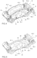
- the intercalary device 34 is visible in more detail on the Figures 4 to 7 .
- the intermediate device 34 comprises an upstream side 36 cooperating with the piston and a downstream side 38 cooperating with the rear axial face of the inner brake pad P1.
- the upstream side 36 receives the thrust exerted by the piston and the downstream side ensures a balanced distribution of the thrust on the brake pad.
- the intermediate device comprises a first part 40 on the upstream side 36 in contact with the nose of the piston and two second parts 42.1, 42.2 on the downstream side cooperating with the brake pad.
- each second part 42.1, 42.2 comprises a first part 44.1, 44.2 substantially in the shape of a disc and a second part forming a branch 46.1, 46.2 extending substantially tangentially.
- the two branches 46.1, 46.1 are oriented so as to extend in a plane orthogonal to the X axis laterally outwardly of a portion 44.1, 44.2 respectively.
- the free lateral ends 48.1, 48.2 of the two branches 46.1, 46.2 are intended to fit into the grooves of the yoke and ensure absorption of the radial force.
- Each part 44.1, 44.2 bears against the rear face of the pad in an area corresponding to that against which one of the pistons of a twin-piston disc brake would bear.
- the shape and dimensions of the discs of the parts 44.1, 44.2 correspond to the outer contour of the contact surface between each piston and the pad in a twin-piston brake.
- the first part 40 is mechanically connected to the second parts 42.1, 42.2 by two ball joints 50.1, 50.2 located substantially in the center of each of the parts 44.1, 44.2.
- the first part receives a thrust force from the piston along the piston sliding axis X, which is distributed over the two parts 44.1, 44.2 of the second part 42 in a balanced manner.
- the first part, the second part 42 and the two ball joints form a lever.
- the inner brake pad P1 receives balanced thrust forces at the two contact areas of the pistons. The inner pad therefore sees the thrust forces applied by two pistons.
- Axial securing means are provided between the piston and the intermediate device so that, when the piston moves back, the inner pad P1 moves away from the disc.
- the axial securing means are such that they form an articulation between the piston and the intermediate device, this articulation advantageously being a ball joint between the piston and the intermediate device.
- they may have radial clearance so as to support the movement of the brake pad P1 under torque during a conventional braking phase.
- the axial securing means comprise a housing 52 formed in the first part 40 and provided with a window 54 opening in the upstream face, the housing also opens towards the arch of the stirrup.
- the dimensions of the window 54 in a plane orthogonal to the X axis are smaller than those of the housing 52 so that, seen from the inside of the housing 52, the window 54 is bordered by a rim 56.
- the piston comprises a connection element 58 projecting axially from the face 26.
- the connection element 58 comprises a head 60 connected to the nose by a rod 61 of transverse dimension smaller than those of the head 60 and the window 54.
- the transverse dimensions of the head 60 are for their part greater than those of the window 54 and smaller than that of the housing 52.
- the head 60 When the head 60 is inserted into the housing 52 through its upper opening by sliding, the rod 61 slides in the window 54.
- the head 60 cooperates with the rim 56 and axially secures the piston and the intermediate device at least in a movement from downstream to upstream, while providing a swiveling capability between the piston and the first part.
- a clearance is provided between the connection element 58 and the housing and the window of the first part 40.
- axial securing means are particularly advantageous because they ensure automatic securing of the piston and the intermediate device when the brake caliper is pivoted around one of its columns C1 to close the brake, as illustrated by the figures 1 , 2 , 3 .
- the connecting element 58 approaches the housing 52 ( figure 2 ) until it penetrates into it.
- the connecting element 58 is carried by the first part and the housing is formed in the piston.
- the ball joints of the ball joints are mounted in the second part.
- the ball joints of the ball joints are mounted in the first part.
- the transfer device is secured to the piston in a captive manner when the piston is mounted in the caliper body.
- the intermediate device is advantageously made of treated steel, preferably the same steel as that of the piston.
- the piston is moved axially towards the disc.
- the piston applies a thrust force to the first part 40 which transmits it to the two second parts 42 by distributing it in a balanced manner between the two parts 44.1, 44.2 due to the rocker-type assembly.
- the thrust force is thus distributed over the brake pad.
- the pad moves axially, a plane of the front face remaining parallel to the plane of the disc.
- the two second parts slide relative to the yoke with the inner brake pad, the branches sliding in the grooves. By reaction, the caliper slides and the caliper nose pushes the outer plate towards the brake disc.
- the piston moves back, taking with it the intermediate device via the cooperation of the connection element 58 and the housing 52, and the brake pads are guided in translation by the springs R1, R2.
- the electromechanical actuator When applying the parking brake, the brake disc is generally stationary, the electromechanical actuator is activated to slide the piston towards the disc.
- the piston applies a thrust force to the first part 40 which transmits it to the two second parts 42 by distributing it in a balanced manner between the two parts 44.1, 44.2 due to the rocker-type assembly.
- the thrust force is thus distributed over the brake pad.
- the two second parts 42.1, 42.2 slide relative to the yoke 15 with the inner brake pad P1, the branches sliding in the grooves.
- the caliper 12 slides and the caliper nose pushes the outer brake pad P2 towards the brake disc.
- the electromechanical actuator 17 is controlled to return the piston to the caliper, the piston slides axially away from the disc, taking with it the intermediate device via the cooperation of the connection element 58 and the housing 52, and the brake pads are guided in axial translation by the springs R1, R2.
- a caliper comprising a body comprising a housing for a piston and an electromechanical actuator and a vault of a twin-piston disc brake.
- a piston provided with a connection element 58 is mounted in the housing.
- a yoke of a twin-piston brake is also manufactured.
- the stirrup and the yoke are assembled by mounting a C1 column.
- the stirrup is arranged in the raised position as in the figure 1
- the inner P1 and outer P2 brake pads of a twin-piston brake are mounted in the yoke.
- the spacer device is mounted against the pad support of the inner brake pad, and the free ends of the branches of the second parts are slid into the springs mounted in the grooves.
- the caliper is pivoted downwards, the head 60 of the connecting element 58 enters the housing 52 and the rod 61 slides in the window 54.
- the piston and the intermediate device are assembled.
- the second C2 column is put in place.
- the disc brake is ready to be mounted on a steering knuckle of a motor vehicle.
- the addition of the spacer device adds little complexity to the brake manufacturing process and the brake pad replacement process.
- the second parts reproducing the support of the pistons on the brake pads are circular in shape, which is the classic shape of a disc brake piston.
- the addition of the intermediate device provides an additional degree of freedom in choosing the shape and dimensions of the thrust application areas.
- the second parts can have any shape or any section adapted to best distribute the braking forces on the brake pad, for example the two parts have different surfaces and/or different shapes depending on the stresses undergone by the different areas of the brake pad.
- the second parts are removably attached to the inner brake pad P1, so as to be axially secured to it.
- the intercalary device is then replaced each time the pad is changed or not.
- the second parts are permanently fixed to the pad support.
- the invention also relates to a brake pad comprising an intermediate device ensuring a distribution of the thrust force in at least two zones offset transversely from the upstream face of the inner brake pad. The intermediate device is then replaced each time the pad is changed.
- the intermediate device allows the distribution of the thrust force exerted by the piston into more than two zones, for example into four zones, the centers of the four zones being for example the vertices of a rectangle.
- the intercalated device according to the invention offers the advantage of allowing the use of the single-piston electromechanical actuator of disc brakes, thus the production of disc brakes having a support section identical to a twin-piston brake or even with more than two pistons is simplified and does not require the redevelopment of an electromechanical actuator allowing the movement of two pistons or more.
- the mass and size are significantly reduced compared to an electromechanical actuator allowing the movement of two pistons or more.
- the present invention makes it possible to produce variable support sections depending on the support for a pad, for example to compensate for differential wear.
- the invention also applies to a disc brake whose actuator comprises several pistons, for example two, and making it possible to distribute the thrust forces of the two pistons over a large brake pad, in particular for a pad of considerable length.
- the intercalary device is particularly advantageous in the case of an electromechanically controlled disc brake, whether or not it incorporates a parking brake.
- the intercalary device can be applied to a disc brake incorporating a mechanically controlled parking brake, for example by cable, and also a hydraulic disc brake with or without a parking brake function.
Landscapes
- Engineering & Computer Science (AREA)
- General Engineering & Computer Science (AREA)
- Mechanical Engineering (AREA)
- Braking Arrangements (AREA)
Claims (14)
- Abstandshaltevorrichtung (34) für eine Scheibenbremse, wobei die Abstandshaltevorrichtung dazu bestimmt ist, zwischen einen Kolben der Scheibenbremse und einem inneren Bremsbelagträger eingefügt zu werden, umfassend ein erstes Bauteil (40) und mindestens zwei zweite Bauteile (42.1, 42.2), ein erstes Kugelgelenk (42.1, 42.2) zwischen dem ersten Bauteil (40) und jedem zweiten Bauteil (42.1, 42.2), wobei das erste Bauteil (40) dazu konfiguriert ist, durch ein zweites Kugelgelenk am Kolben befestigt zu werden, und wobei die zweiten Bauteile (42.1, 42.2) dazu bestimmt sind, auf einem Belagträger eines Bremsbelags in Anlage zu kommen.
- Abstandshaltevorrichtung nach dem vorhergehenden Anspruch, wobei jedes zweite Bauteil (42.1, 42.2) eine Oberfläche zum Übertragen einer Schubkraft auf den Belagträger und einen Abschnitt umfasst, der dazu bestimmt ist, mit dem Gabelkopf zusammenzuwirken, um seine Führung in dem Gabelkopf zu gewährleisten.
- Bremsbelag, die einen Belagträger und ein Reibungsmaterial und eine Abstandshaltevorrichtung nach Anspruch 1 oder 2 umfasst, die an einer Fläche des Bremsbelagsträgers fixiert ist, die derjenigen gegenüberliegt, die das Reibungsmaterial trägt.
- Scheibenbremse, umfassend einen Gabelkopf (15), mindestens einen ersten Bremsbelag (P1), der im Gabelkopf (15) verschiebbar angebracht ist, wobei der erste Bremsbelag (P1) einen Belagträger und ein Reibungsmaterial umfasst, einen Bremssattel (12), der mindestens einen Kolben (16) umfasst, der in dem Bremssattel (12) verschiebbar angebracht ist, um den ersten Bremsbelag (P1) im Verhältnis zum Gabelkopf (15) zu bewegen, mindestens ein Stellglied (17), das so konfiguriert ist, dass er den Kolben (16) axial bewegt, dadurch gekennzeichnet, dass die Scheibenbremse eine Abstandshaltevorrichtung (34) nach Anspruch 1 oder Anspruch 2 umfasst, wobei die Abstandshaltevorrichtung (34) zwischen dem Kolben (16) und dem ersten Bremsbelag (P1) eingefügt ist und eine Bremsausgleichsvorrichtung bildet, um die vom Kolben (16) ausgeübte Schubkraft auf mindestens zwei Bereiche des ersten Bremsbelags (P1) zu verteilen, die sich mindestens teilweise von dem Vorsprung des Kolbens auf den ersten Bremsbelag (P1) unterscheiden.
- Scheibenbremse nach Anspruch 4, wobei der Gabelkopf (15) mindestens zwei Führungsnuten (19) für zwei Laschen des ersten Bremsbelags umfasst und wobei die zweiten Bauteile (42.1, 42.2) jeweils einen Zweig (46.1, 46.2) umfassen, dessen eines freies Ende (48.1, 48.2) in einer der Nuten (19) angebracht ist.
- Scheibenbremse nach einem der Ansprüche 4 bis 5, wobei das Kugelgelenk zwischen dem ersten Bauteil (40) und dem Kolben (16) ein erstes Element, das fest mit dem Kolben verbunden ist, und ein zweites Element umfasst, das fest mit dem ersten Bauteil verbunden ist, wobei das erste Element oder das zweite Element in das zweite Element bzw. das erste Element eindringt, um ein Kugelgelenk zwischen dem Kolben und der Abstandshaltevorrichtung zu bilden und eine axiale Verbindung zwischen dem Kolben und der Abstandshaltevorrichtung zumindest dann zu gewährleisten, wenn der Kolben in den Bremssattel zurückkehrt.
- Scheibenbremse nach einem der Ansprüche 4 bis 6, wobei die mindestens zwei Bereiche quer zueinander versetzt sind.
- Scheibenbremse nach einem der Ansprüche 4 bis 7, wobei die mindestens zwei Bereiche eine Kreisform haben.
- Scheibenbremse nach Anspruch 8, wobei die ersten Kugelgelenke (50.1, 50.2) derart angeordnet sind, dass ihr Vorsprung auf dem ersten Bremsbelag in der Mitte der Bereiche liegt.
- Scheibenbremse nach einem der Ansprüche 4 bis 9, umfassend einen zweiten Bremsbelag (P2), einen ersten Führungsbolzen (C1) und einen zweiten Führungsbolzen (C2), der ein Gleiten zwischen dem Bremssattel (12) und dem Gabelkopf (15) ermöglicht, wobei mindestens der zweite Führungsbolzen (C2) die Drehung des Bremssattels um den ersten Führungsbolzen (C1) ermöglicht, und wobei der Bremssattel (12) ein Gewölbe (32) und eine Nase (30) umfasst, die dazu bestimmt ist, eine Kraft auf den zweiten Bremsbelag (P2) auszuüben.
- Scheibenbremse nach dem vorhergehenden Anspruch in Kombination mit Anspruch 6, wobei eines des ersten und des zweiten Elements eine Aufnahme (52), die sich in Richtung des Gewölbes des Bremssattels öffnet, und ein Fenster (54) umfasst, das sich in Richtung des zweiten Elements bzw. des ersten Elements öffnet, und das zweite oder das erste Element einen Kopf (60) und eine Stange (61) umfasst, wobei der Kopf (60) so bemessen ist, dass er in die Aufnahme (52) eindringt und einen axialen Anschlag zwischen dem Kolben (16) und der Abstandshaltevorrichtung (34) bildet.
- Scheibenbremse nach einem der vorhergehenden Ansprüche 4 bis 11, wobei der Bremssattel (12) einen Kolben (16) und ein Stellglied (17) des Kolbens (16) umfasst, und wobei der Gabelkopf (15) und der erste Bremsbelag (P1) die Abmessungen eines Bremsbelags einer Doppelkolben-Scheibenbremse aufweisen.
- Scheibenbremse nach einem der vorhergehenden Ansprüche 4 bis 12, wobei das Stellglied (17) ein elektromechanisches Stellglied ist.
- Verfahren zum Herstellen einer Bremssattel-Scheibenbremse nach Anspruch 10 oder 11, umfassend:- Herstellen eines Bremssattels, der einen Körper umfasst, der eine Aufnahme für einen Kolben und ein elektromechanisches Stellglied sowie eine Gewölbe für eine Doppelkolben-Scheibenbremse umfasst,- Herstellen eines Kolbens, der mit einem Verbindungselement versehen ist,- Anbringen des Kolbens in der Aufnahme des Bremssattelkörpers,- Herstellen eines Gabelkopfs einer Doppelkolbenbremse,- Montieren des Bremssattels und des Gabelkopfs durch Anbringen eines Führungsbolzens zwischen dem Gabelkopf und dem Bremssattel,- Bringen des Bremssattels in eine angehobene Position,- Anbringen des inneren und des äußeren Bremsbelags einer Doppelkolbenbremse in dem Gabelkopf,- Herstellen einer Abstandshaltevorrichtung,- Anbringen der Abstandshaltevorrichtung auf dem Belagträger des inneren Bremsbelags,- Schwenken des Bremssattels in Richtung des Gabelkopfs, wobei das Verbindungselement des Kolbens mit dem ersten Bauteil der Abstandshaltevorrichtung zusammenwirkt,- Installieren des zweiten Führungsbolzens zwischen dem Gabelkopf und dem Bremssattel.
Applications Claiming Priority (2)
| Application Number | Priority Date | Filing Date | Title |
|---|---|---|---|
| FR1871685A FR3088697B1 (fr) | 2018-11-21 | 2018-11-21 | Frein a disque offrant une répartition equilibrée des efforts de poussée appliqués par un piston sur au moins une plaquette de frein |
| PCT/FR2019/052762 WO2020104752A1 (fr) | 2018-11-21 | 2019-11-20 | Frein à disque offrant une répartition equilibrée des efforts de poussée appliqués par un piston sur au moins une plaquette de frein |
Publications (2)
| Publication Number | Publication Date |
|---|---|
| EP3864314A1 EP3864314A1 (de) | 2021-08-18 |
| EP3864314B1 true EP3864314B1 (de) | 2024-11-20 |
Family
ID=66676605
Family Applications (1)
| Application Number | Title | Priority Date | Filing Date |
|---|---|---|---|
| EP19829289.8A Active EP3864314B1 (de) | 2018-11-21 | 2019-11-20 | Scheibenbremse mit ausgeglichener verteilung der durch einen kolben auf mindestens einen bremsbelag aufgebrachten schubkräfte |
Country Status (5)
| Country | Link |
|---|---|
| US (1) | US11867244B2 (de) |
| EP (1) | EP3864314B1 (de) |
| CN (1) | CN113167344B (de) |
| FR (1) | FR3088697B1 (de) |
| WO (1) | WO2020104752A1 (de) |
Families Citing this family (10)
| Publication number | Priority date | Publication date | Assignee | Title |
|---|---|---|---|---|
| FR3097023B1 (fr) | 2019-06-04 | 2021-06-25 | Foundation Brakes France | Réducteur épicycloïdal comprenant au moins une pièce de transmission d’effort axial formant un chemin d’effort radialement excentré |
| IT202000030986A1 (it) * | 2020-12-16 | 2022-06-16 | Brembo Spa | Freno a disco con pinza flottante e metodo di operazione di un freno a disco con pinza flottante |
| DE102021213029A1 (de) * | 2021-11-19 | 2023-05-25 | Zf Active Safety Gmbh | Kraftübertragungsvorrichtung für eine Scheibenbremse |
| CN114110056A (zh) * | 2021-11-30 | 2022-03-01 | 浙江吉利控股集团有限公司 | 制动卡钳、后桥总成和车辆 |
| FR3129901B1 (fr) * | 2021-12-03 | 2024-04-26 | Hitachi Astemo France | Système de freinage à actionnement équilibré |
| FR3160222A1 (fr) * | 2024-03-15 | 2025-09-19 | Hitachi Astemo France | Écrou de vis à billes à collet central pour frein à étrier |
| WO2025016680A1 (fr) * | 2023-07-19 | 2025-01-23 | Hitachi Astemo France | Écrou de vis à billes à collet central pour frein à étrier |
| FR3151364A1 (fr) * | 2023-07-19 | 2025-01-24 | Hitachi Astemo France | Dispositif de freinage à tête de poussée mobile pour frein à étrier |
| CN117345789A (zh) * | 2023-11-08 | 2024-01-05 | 重庆中帝机械制造股份有限公司 | 双卡钳气动盘式制动器、车桥总成工程机械车桥 |
| DE102024203811A1 (de) * | 2024-04-24 | 2025-10-30 | Zf Active Safety Gmbh | Fahrzeugbremse sowie Bremsklotzsatz |
Family Cites Families (25)
| Publication number | Priority date | Publication date | Assignee | Title |
|---|---|---|---|---|
| US3743060A (en) * | 1970-10-27 | 1973-07-03 | Kelsey Hayes Co | Servo action parking brake with rotary actuator |
| US4823920A (en) * | 1988-05-02 | 1989-04-25 | Kelsey-Hayes Company | Sliding caliper disc brake and brake shoe assembly therefor |
| US5363943A (en) * | 1991-10-15 | 1994-11-15 | Honda Giken Kogyo Kabushiki Kaisha | Disk brake apparatus for vehicle |
| DE4436457A1 (de) * | 1994-10-12 | 1996-04-18 | Knorr Bremse Systeme | Bremsbelag für Teilbelag-Scheibenbremsen, insbesondere von Schienenfahrzeugen |
| DE10347792A1 (de) * | 2003-10-14 | 2005-05-12 | Bosch Gmbh Robert | Radbremse |
| DE102005030620A1 (de) * | 2004-10-13 | 2006-04-20 | Knorr-Bremse Systeme für Nutzfahrzeuge GmbH | Scheibenbremse in selbstverstärkerder Bauart |
| DE102006010754A1 (de) * | 2006-03-08 | 2007-09-20 | Haldex Brake Products Ab | Scheibenbremse |
| DE102008019003A1 (de) * | 2008-04-14 | 2009-10-15 | Tmd Friction Services Gmbh | Bremsbelag mit Adapter für Scheibenbremsen |
| DE102009050332A1 (de) * | 2009-10-22 | 2011-05-05 | Knorr-Bremse Systeme für Nutzfahrzeuge GmbH | Selbstverstärkende Scheibenbremse und Bremsbelag dafür |
| DE102010019765B4 (de) * | 2010-05-07 | 2025-02-13 | Knorr-Bremse Systeme für Schienenfahrzeuge GmbH | Bremsbelag für eine Teilbelag-Scheibenbremse |
| CN101975234B (zh) * | 2010-10-18 | 2012-07-04 | 常州南车铁马科技实业有限公司 | 带调整器的列车制动闸片 |
| DE102011103823A1 (de) * | 2011-06-09 | 2012-12-13 | Knorr-Bremse Systeme für Nutzfahrzeuge GmbH | Mehrfachkolben-Scheibenbremse |
| DE102012012833A1 (de) * | 2012-06-28 | 2014-01-02 | Knorr-Bremse Systeme für Nutzfahrzeuge GmbH | Scheibenbremse für ein Nutzfahrzeug sowie Bremsbelag für eine Scheibenbremse |
| DE102012012818B4 (de) * | 2012-06-28 | 2015-08-20 | Knorr-Bremse Systeme für Nutzfahrzeuge GmbH | Scheibenbremse für ein Nutzfahrzeug |
| RU2671424C2 (ru) * | 2013-10-02 | 2018-10-31 | Бендикс Спайсер Фаундейшн Брейк Ллк | Система и способ установки и удержания колодки дискового тормоза |
| FR3024516B1 (fr) | 2014-07-30 | 2018-01-19 | Chassis Brakes International B.V. | Reducteur de couple |
| GB201514925D0 (en) * | 2015-08-21 | 2015-10-07 | Caparo Vehicle Products Ltd | A brake caliper,a braking apparatus and a vehicle |
| DE202016003835U1 (de) * | 2016-06-21 | 2016-09-13 | Haldex Brake Products Ab | Scheibenbremse |
| DE102016213645A1 (de) * | 2016-07-26 | 2018-02-01 | Robert Bosch Gmbh | Verfahren zum Betreiben einer automatisierten Feststellbremse |
| DE102016116967A1 (de) * | 2016-09-09 | 2018-03-15 | Knorr-Bremse Systeme für Nutzfahrzeuge GmbH | Scheibenbremse für Nutzfahrzeuge |
| FR3059745B1 (fr) | 2016-12-07 | 2020-08-14 | Foundation Brakes France | Entraineur de piston d'etrier de frein electromecanique integrant une face antifriction |
| US10563714B2 (en) * | 2017-04-18 | 2020-02-18 | Mando Corporation | Oversized brake piston footing |
| FR3067321B1 (fr) | 2017-06-12 | 2020-08-14 | Foundation Brakes France | Modification de la trajectoire d'une roue de vehicule en cas de defaillance de systeme de direction |
| FR3067428B1 (fr) | 2017-06-12 | 2019-07-12 | Foundation Brakes France | Etrier de frein pour vehicule comprenant une unite de commande de freinage |
| FR3076331B1 (fr) | 2018-01-02 | 2020-02-14 | Foundation Brakes France | Actionneur de frein et procede de commande associe |
-
2018
- 2018-11-21 FR FR1871685A patent/FR3088697B1/fr active Active
-
2019
- 2019-11-20 EP EP19829289.8A patent/EP3864314B1/de active Active
- 2019-11-20 WO PCT/FR2019/052762 patent/WO2020104752A1/fr not_active Ceased
- 2019-11-20 CN CN201980077079.9A patent/CN113167344B/zh active Active
- 2019-11-20 US US17/294,626 patent/US11867244B2/en active Active
Also Published As
| Publication number | Publication date |
|---|---|
| CN113167344B (zh) | 2024-04-02 |
| EP3864314A1 (de) | 2021-08-18 |
| US11867244B2 (en) | 2024-01-09 |
| FR3088697A1 (fr) | 2020-05-22 |
| CN113167344A (zh) | 2021-07-23 |
| FR3088697B1 (fr) | 2021-06-25 |
| US20220010852A1 (en) | 2022-01-13 |
| WO2020104752A1 (fr) | 2020-05-28 |
Similar Documents
| Publication | Publication Date | Title |
|---|---|---|
| EP3864314B1 (de) | Scheibenbremse mit ausgeglichener verteilung der durch einen kolben auf mindestens einen bremsbelag aufgebrachten schubkräfte | |
| EP0988466B1 (de) | Scheibenbremse mit vorgespanntem führungsrohr | |
| FR2680215A1 (fr) | Frein a disque a garnitures partielles et a cadre flottant, plaquette de frein et ressort de plaquette. | |
| FR3016011A1 (fr) | Actionneur entraine par pignon a glissiere axiale, et frein a tambour et dispositif de freinage ainsi equipes | |
| EP2649341B1 (de) | Scheibenbremse mit verriegelungselement zur verriegelung des umsetzungseinsatzes mit einer verriegelung | |
| EP0028955B1 (de) | Schwimmsattel-Scheibenbremse | |
| FR2537506A1 (fr) | Agencement pour monter, sur un montant de suspension, un arbre tournant d'une roue d'un vehicule | |
| FR2746469A1 (fr) | Patin de friction pour frein a disque | |
| EP0366509B1 (de) | Bremse mit zwei Scheiben mit festem Abstand | |
| FR2876427A1 (fr) | Element de friction muni d'un moyen de rappel et frein a disque comportant un tel element de friction | |
| EP4356019A1 (de) | Scheibenbremse mit elektromechanischer feststellbremse | |
| EP3551905B1 (de) | Treiber für elektromechanischen bremssattelkolben mit einer reibungsfreien seite | |
| EP0803031A1 (de) | Scheibenbremse mit mechanischer betätigungsvorrichtung | |
| EP0699280B1 (de) | Schwimmsattel scheibenbremse | |
| EP0966620B1 (de) | Hybrides mehrscheibenbremssystem | |
| FR2526902A1 (fr) | Frein a disque avec limiteur de la rotation du piston autour de son axe | |
| FR2755195A1 (fr) | Dispositif de freinage integre a rigidite accrue | |
| EP0395460B1 (de) | Schwimmsattel-Scheibenbremse | |
| EP0120738B2 (de) | Scheibenbremse mit verschiebbarem Sattel | |
| EP0018913A1 (de) | Scheibenbremse | |
| EP4559767A1 (de) | Scheibenbremse, insbesondere für ein kraftfahrzeug | |
| FR3126147A1 (fr) | Piston pour moyens de commande du serrage d’un frein à disque, notamment pour véhicule automobile. | |
| FR3162810A1 (fr) | Dispositif pour frein à étrier comprenant un anneau d’étanchéité emmanché sur une tête de poussée | |
| WO2023139341A1 (fr) | Système de freinage ferroviaire pour véhicule ferroviaire, à freins à au moins un sabot, et véhicule ferroviaire pourvu d'un tel système | |
| FR3151364A1 (fr) | Dispositif de freinage à tête de poussée mobile pour frein à étrier |
Legal Events
| Date | Code | Title | Description |
|---|---|---|---|
| STAA | Information on the status of an ep patent application or granted ep patent |
Free format text: STATUS: UNKNOWN |
|
| STAA | Information on the status of an ep patent application or granted ep patent |
Free format text: STATUS: THE INTERNATIONAL PUBLICATION HAS BEEN MADE |
|
| PUAI | Public reference made under article 153(3) epc to a published international application that has entered the european phase |
Free format text: ORIGINAL CODE: 0009012 |
|
| STAA | Information on the status of an ep patent application or granted ep patent |
Free format text: STATUS: REQUEST FOR EXAMINATION WAS MADE |
|
| 17P | Request for examination filed |
Effective date: 20210512 |
|
| AK | Designated contracting states |
Kind code of ref document: A1 Designated state(s): AL AT BE BG CH CY CZ DE DK EE ES FI FR GB GR HR HU IE IS IT LI LT LU LV MC MK MT NL NO PL PT RO RS SE SI SK SM TR |
|
| RAP3 | Party data changed (applicant data changed or rights of an application transferred) |
Owner name: HITACHI ASTEMO FRANCE |
|
| DAV | Request for validation of the european patent (deleted) | ||
| DAX | Request for extension of the european patent (deleted) | ||
| STAA | Information on the status of an ep patent application or granted ep patent |
Free format text: STATUS: EXAMINATION IS IN PROGRESS |
|
| 17Q | First examination report despatched |
Effective date: 20230203 |
|
| GRAP | Despatch of communication of intention to grant a patent |
Free format text: ORIGINAL CODE: EPIDOSNIGR1 |
|
| STAA | Information on the status of an ep patent application or granted ep patent |
Free format text: STATUS: GRANT OF PATENT IS INTENDED |
|
| INTG | Intention to grant announced |
Effective date: 20240617 |
|
| GRAS | Grant fee paid |
Free format text: ORIGINAL CODE: EPIDOSNIGR3 |
|
| GRAA | (expected) grant |
Free format text: ORIGINAL CODE: 0009210 |
|
| STAA | Information on the status of an ep patent application or granted ep patent |
Free format text: STATUS: THE PATENT HAS BEEN GRANTED |
|
| AK | Designated contracting states |
Kind code of ref document: B1 Designated state(s): AL AT BE BG CH CY CZ DE DK EE ES FI FR GB GR HR HU IE IS IT LI LT LU LV MC MK MT NL NO PL PT RO RS SE SI SK SM TR |
|
| REG | Reference to a national code |
Ref country code: GB Ref legal event code: FG4D Free format text: NOT ENGLISH |
|
| REG | Reference to a national code |
Ref country code: CH Ref legal event code: EP |
|
| REG | Reference to a national code |
Ref country code: DE Ref legal event code: R096 Ref document number: 602019062327 Country of ref document: DE |
|
| REG | Reference to a national code |
Ref country code: IE Ref legal event code: FG4D Free format text: LANGUAGE OF EP DOCUMENT: FRENCH |
|
| REG | Reference to a national code |
Ref country code: LT Ref legal event code: MG9D |
|
| REG | Reference to a national code |
Ref country code: NL Ref legal event code: MP Effective date: 20241120 |
|
| PG25 | Lapsed in a contracting state [announced via postgrant information from national office to epo] |
Ref country code: HR Free format text: LAPSE BECAUSE OF FAILURE TO SUBMIT A TRANSLATION OF THE DESCRIPTION OR TO PAY THE FEE WITHIN THE PRESCRIBED TIME-LIMIT Effective date: 20241120 Ref country code: PT Free format text: LAPSE BECAUSE OF FAILURE TO SUBMIT A TRANSLATION OF THE DESCRIPTION OR TO PAY THE FEE WITHIN THE PRESCRIBED TIME-LIMIT Effective date: 20250320 Ref country code: IS Free format text: LAPSE BECAUSE OF FAILURE TO SUBMIT A TRANSLATION OF THE DESCRIPTION OR TO PAY THE FEE WITHIN THE PRESCRIBED TIME-LIMIT Effective date: 20250320 |
|
| PG25 | Lapsed in a contracting state [announced via postgrant information from national office to epo] |
Ref country code: NL Free format text: LAPSE BECAUSE OF FAILURE TO SUBMIT A TRANSLATION OF THE DESCRIPTION OR TO PAY THE FEE WITHIN THE PRESCRIBED TIME-LIMIT Effective date: 20241120 Ref country code: FI Free format text: LAPSE BECAUSE OF FAILURE TO SUBMIT A TRANSLATION OF THE DESCRIPTION OR TO PAY THE FEE WITHIN THE PRESCRIBED TIME-LIMIT Effective date: 20241120 |
|
| REG | Reference to a national code |
Ref country code: AT Ref legal event code: MK05 Ref document number: 1743832 Country of ref document: AT Kind code of ref document: T Effective date: 20241120 |
|
| PG25 | Lapsed in a contracting state [announced via postgrant information from national office to epo] |
Ref country code: BG Free format text: LAPSE BECAUSE OF FAILURE TO SUBMIT A TRANSLATION OF THE DESCRIPTION OR TO PAY THE FEE WITHIN THE PRESCRIBED TIME-LIMIT Effective date: 20241120 |
|
| PG25 | Lapsed in a contracting state [announced via postgrant information from national office to epo] |
Ref country code: ES Free format text: LAPSE BECAUSE OF FAILURE TO SUBMIT A TRANSLATION OF THE DESCRIPTION OR TO PAY THE FEE WITHIN THE PRESCRIBED TIME-LIMIT Effective date: 20241120 |
|
| PG25 | Lapsed in a contracting state [announced via postgrant information from national office to epo] |
Ref country code: NO Free format text: LAPSE BECAUSE OF FAILURE TO SUBMIT A TRANSLATION OF THE DESCRIPTION OR TO PAY THE FEE WITHIN THE PRESCRIBED TIME-LIMIT Effective date: 20250220 |
|
| PG25 | Lapsed in a contracting state [announced via postgrant information from national office to epo] |
Ref country code: AT Free format text: LAPSE BECAUSE OF FAILURE TO SUBMIT A TRANSLATION OF THE DESCRIPTION OR TO PAY THE FEE WITHIN THE PRESCRIBED TIME-LIMIT Effective date: 20241120 Ref country code: GR Free format text: LAPSE BECAUSE OF FAILURE TO SUBMIT A TRANSLATION OF THE DESCRIPTION OR TO PAY THE FEE WITHIN THE PRESCRIBED TIME-LIMIT Effective date: 20250221 Ref country code: LV Free format text: LAPSE BECAUSE OF FAILURE TO SUBMIT A TRANSLATION OF THE DESCRIPTION OR TO PAY THE FEE WITHIN THE PRESCRIBED TIME-LIMIT Effective date: 20241120 |
|
| PG25 | Lapsed in a contracting state [announced via postgrant information from national office to epo] |
Ref country code: PL Free format text: LAPSE BECAUSE OF FAILURE TO SUBMIT A TRANSLATION OF THE DESCRIPTION OR TO PAY THE FEE WITHIN THE PRESCRIBED TIME-LIMIT Effective date: 20241120 |
|
| PG25 | Lapsed in a contracting state [announced via postgrant information from national office to epo] |
Ref country code: RS Free format text: LAPSE BECAUSE OF FAILURE TO SUBMIT A TRANSLATION OF THE DESCRIPTION OR TO PAY THE FEE WITHIN THE PRESCRIBED TIME-LIMIT Effective date: 20250220 |
|
| REG | Reference to a national code |
Ref country code: CH Ref legal event code: PL |
|
| PG25 | Lapsed in a contracting state [announced via postgrant information from national office to epo] |
Ref country code: SM Free format text: LAPSE BECAUSE OF FAILURE TO SUBMIT A TRANSLATION OF THE DESCRIPTION OR TO PAY THE FEE WITHIN THE PRESCRIBED TIME-LIMIT Effective date: 20241120 |
|
| PG25 | Lapsed in a contracting state [announced via postgrant information from national office to epo] |
Ref country code: DK Free format text: LAPSE BECAUSE OF FAILURE TO SUBMIT A TRANSLATION OF THE DESCRIPTION OR TO PAY THE FEE WITHIN THE PRESCRIBED TIME-LIMIT Effective date: 20241120 |
|
| PG25 | Lapsed in a contracting state [announced via postgrant information from national office to epo] |
Ref country code: LU Free format text: LAPSE BECAUSE OF NON-PAYMENT OF DUE FEES Effective date: 20241120 |
|
| REG | Reference to a national code |
Ref country code: CH Ref legal event code: PL |
|
| PG25 | Lapsed in a contracting state [announced via postgrant information from national office to epo] |
Ref country code: EE Free format text: LAPSE BECAUSE OF FAILURE TO SUBMIT A TRANSLATION OF THE DESCRIPTION OR TO PAY THE FEE WITHIN THE PRESCRIBED TIME-LIMIT Effective date: 20241120 |
|
| PG25 | Lapsed in a contracting state [announced via postgrant information from national office to epo] |
Ref country code: CH Free format text: LAPSE BECAUSE OF NON-PAYMENT OF DUE FEES Effective date: 20241130 |
|
| PG25 | Lapsed in a contracting state [announced via postgrant information from national office to epo] |
Ref country code: RO Free format text: LAPSE BECAUSE OF FAILURE TO SUBMIT A TRANSLATION OF THE DESCRIPTION OR TO PAY THE FEE WITHIN THE PRESCRIBED TIME-LIMIT Effective date: 20241120 |
|
| PG25 | Lapsed in a contracting state [announced via postgrant information from national office to epo] |
Ref country code: SK Free format text: LAPSE BECAUSE OF FAILURE TO SUBMIT A TRANSLATION OF THE DESCRIPTION OR TO PAY THE FEE WITHIN THE PRESCRIBED TIME-LIMIT Effective date: 20241120 |
|
| PG25 | Lapsed in a contracting state [announced via postgrant information from national office to epo] |
Ref country code: CZ Free format text: LAPSE BECAUSE OF FAILURE TO SUBMIT A TRANSLATION OF THE DESCRIPTION OR TO PAY THE FEE WITHIN THE PRESCRIBED TIME-LIMIT Effective date: 20241120 |
|
| PG25 | Lapsed in a contracting state [announced via postgrant information from national office to epo] |
Ref country code: IT Free format text: LAPSE BECAUSE OF FAILURE TO SUBMIT A TRANSLATION OF THE DESCRIPTION OR TO PAY THE FEE WITHIN THE PRESCRIBED TIME-LIMIT Effective date: 20241120 |
|
| REG | Reference to a national code |
Ref country code: DE Ref legal event code: R097 Ref document number: 602019062327 Country of ref document: DE |
|
| REG | Reference to a national code |
Ref country code: BE Ref legal event code: MM Effective date: 20241130 |
|
| PG25 | Lapsed in a contracting state [announced via postgrant information from national office to epo] |
Ref country code: SE Free format text: LAPSE BECAUSE OF FAILURE TO SUBMIT A TRANSLATION OF THE DESCRIPTION OR TO PAY THE FEE WITHIN THE PRESCRIBED TIME-LIMIT Effective date: 20241120 |
|
| PG25 | Lapsed in a contracting state [announced via postgrant information from national office to epo] |
Ref country code: MC Free format text: LAPSE BECAUSE OF FAILURE TO SUBMIT A TRANSLATION OF THE DESCRIPTION OR TO PAY THE FEE WITHIN THE PRESCRIBED TIME-LIMIT Effective date: 20241120 |
|
| PLBE | No opposition filed within time limit |
Free format text: ORIGINAL CODE: 0009261 |
|
| STAA | Information on the status of an ep patent application or granted ep patent |
Free format text: STATUS: NO OPPOSITION FILED WITHIN TIME LIMIT |
|
| PG25 | Lapsed in a contracting state [announced via postgrant information from national office to epo] |
Ref country code: BE Free format text: LAPSE BECAUSE OF NON-PAYMENT OF DUE FEES Effective date: 20241130 |
|
| 26N | No opposition filed |
Effective date: 20250821 |
|
| PG25 | Lapsed in a contracting state [announced via postgrant information from national office to epo] |
Ref country code: IE Free format text: LAPSE BECAUSE OF NON-PAYMENT OF DUE FEES Effective date: 20241120 |
|
| GBPC | Gb: european patent ceased through non-payment of renewal fee |
Effective date: 20250220 |
|
| PGFP | Annual fee paid to national office [announced via postgrant information from national office to epo] |
Ref country code: DE Payment date: 20251022 Year of fee payment: 7 |
|
| PG25 | Lapsed in a contracting state [announced via postgrant information from national office to epo] |
Ref country code: GB Free format text: LAPSE BECAUSE OF NON-PAYMENT OF DUE FEES Effective date: 20250220 |
|
| PGFP | Annual fee paid to national office [announced via postgrant information from national office to epo] |
Ref country code: FR Payment date: 20251023 Year of fee payment: 7 |
|
| PG25 | Lapsed in a contracting state [announced via postgrant information from national office to epo] |
Ref country code: HU Free format text: LAPSE BECAUSE OF FAILURE TO SUBMIT A TRANSLATION OF THE DESCRIPTION OR TO PAY THE FEE WITHIN THE PRESCRIBED TIME-LIMIT; INVALID AB INITIO Effective date: 20191120 |
|
| PG25 | Lapsed in a contracting state [announced via postgrant information from national office to epo] |
Ref country code: CY Free format text: LAPSE BECAUSE OF FAILURE TO SUBMIT A TRANSLATION OF THE DESCRIPTION OR TO PAY THE FEE WITHIN THE PRESCRIBED TIME-LIMIT; INVALID AB INITIO Effective date: 20191120 |