EP4559767A1 - Scheibenbremse, insbesondere für ein kraftfahrzeug - Google Patents
Scheibenbremse, insbesondere für ein kraftfahrzeug Download PDFInfo
- Publication number
- EP4559767A1 EP4559767A1 EP24215588.5A EP24215588A EP4559767A1 EP 4559767 A1 EP4559767 A1 EP 4559767A1 EP 24215588 A EP24215588 A EP 24215588A EP 4559767 A1 EP4559767 A1 EP 4559767A1
- Authority
- EP
- European Patent Office
- Prior art keywords
- screw
- nut
- housing
- brake pad
- caliper
- Prior art date
- Legal status (The legal status is an assumption and is not a legal conclusion. Google has not performed a legal analysis and makes no representation as to the accuracy of the status listed.)
- Pending
Links
Images


Classifications
-
- B—PERFORMING OPERATIONS; TRANSPORTING
- B60—VEHICLES IN GENERAL
- B60T—VEHICLE BRAKE CONTROL SYSTEMS OR PARTS THEREOF; BRAKE CONTROL SYSTEMS OR PARTS THEREOF, IN GENERAL; ARRANGEMENT OF BRAKING ELEMENTS ON VEHICLES IN GENERAL; PORTABLE DEVICES FOR PREVENTING UNWANTED MOVEMENT OF VEHICLES; VEHICLE MODIFICATIONS TO FACILITATE COOLING OF BRAKES
- B60T13/00—Transmitting braking action from initiating means to ultimate brake actuator with power assistance or drive; Brake systems incorporating such transmitting means, e.g. air-pressure brake systems
- B60T13/74—Transmitting braking action from initiating means to ultimate brake actuator with power assistance or drive; Brake systems incorporating such transmitting means, e.g. air-pressure brake systems with electrical assistance or drive
- B60T13/741—Transmitting braking action from initiating means to ultimate brake actuator with power assistance or drive; Brake systems incorporating such transmitting means, e.g. air-pressure brake systems with electrical assistance or drive acting on an ultimate actuator
-
- F—MECHANICAL ENGINEERING; LIGHTING; HEATING; WEAPONS; BLASTING
- F16—ENGINEERING ELEMENTS AND UNITS; GENERAL MEASURES FOR PRODUCING AND MAINTAINING EFFECTIVE FUNCTIONING OF MACHINES OR INSTALLATIONS; THERMAL INSULATION IN GENERAL
- F16D—COUPLINGS FOR TRANSMITTING ROTATION; CLUTCHES; BRAKES
- F16D55/00—Brakes with substantially-radial braking surfaces pressed together in axial direction, e.g. disc brakes
- F16D55/02—Brakes with substantially-radial braking surfaces pressed together in axial direction, e.g. disc brakes with axially-movable discs or pads pressed against axially-located rotating members
- F16D55/22—Brakes with substantially-radial braking surfaces pressed together in axial direction, e.g. disc brakes with axially-movable discs or pads pressed against axially-located rotating members by clamping an axially-located rotating disc between movable braking members, e.g. movable brake discs or brake pads
- F16D55/224—Brakes with substantially-radial braking surfaces pressed together in axial direction, e.g. disc brakes with axially-movable discs or pads pressed against axially-located rotating members by clamping an axially-located rotating disc between movable braking members, e.g. movable brake discs or brake pads with a common actuating member for the braking members
- F16D55/225—Brakes with substantially-radial braking surfaces pressed together in axial direction, e.g. disc brakes with axially-movable discs or pads pressed against axially-located rotating members by clamping an axially-located rotating disc between movable braking members, e.g. movable brake discs or brake pads with a common actuating member for the braking members the braking members being brake pads
- F16D55/226—Brakes with substantially-radial braking surfaces pressed together in axial direction, e.g. disc brakes with axially-movable discs or pads pressed against axially-located rotating members by clamping an axially-located rotating disc between movable braking members, e.g. movable brake discs or brake pads with a common actuating member for the braking members the braking members being brake pads in which the common actuating member is moved axially, e.g. floating caliper disc brakes
-
- F—MECHANICAL ENGINEERING; LIGHTING; HEATING; WEAPONS; BLASTING
- F16—ENGINEERING ELEMENTS AND UNITS; GENERAL MEASURES FOR PRODUCING AND MAINTAINING EFFECTIVE FUNCTIONING OF MACHINES OR INSTALLATIONS; THERMAL INSULATION IN GENERAL
- F16D—COUPLINGS FOR TRANSMITTING ROTATION; CLUTCHES; BRAKES
- F16D65/00—Parts or details
- F16D65/14—Actuating mechanisms for brakes; Means for initiating operation at a predetermined position
- F16D65/16—Actuating mechanisms for brakes; Means for initiating operation at a predetermined position arranged in or on the brake
- F16D65/18—Actuating mechanisms for brakes; Means for initiating operation at a predetermined position arranged in or on the brake adapted for drawing members together, e.g. for disc brakes
- F16D65/183—Actuating mechanisms for brakes; Means for initiating operation at a predetermined position arranged in or on the brake adapted for drawing members together, e.g. for disc brakes with force-transmitting members arranged side by side acting on a spot type force-applying member
-
- F—MECHANICAL ENGINEERING; LIGHTING; HEATING; WEAPONS; BLASTING
- F16—ENGINEERING ELEMENTS AND UNITS; GENERAL MEASURES FOR PRODUCING AND MAINTAINING EFFECTIVE FUNCTIONING OF MACHINES OR INSTALLATIONS; THERMAL INSULATION IN GENERAL
- F16D—COUPLINGS FOR TRANSMITTING ROTATION; CLUTCHES; BRAKES
- F16D55/00—Brakes with substantially-radial braking surfaces pressed together in axial direction, e.g. disc brakes
- F16D2055/0004—Parts or details of disc brakes
- F16D2055/0016—Brake calipers
- F16D2055/002—Brake calipers assembled from a plurality of parts
-
- F—MECHANICAL ENGINEERING; LIGHTING; HEATING; WEAPONS; BLASTING
- F16—ENGINEERING ELEMENTS AND UNITS; GENERAL MEASURES FOR PRODUCING AND MAINTAINING EFFECTIVE FUNCTIONING OF MACHINES OR INSTALLATIONS; THERMAL INSULATION IN GENERAL
- F16D—COUPLINGS FOR TRANSMITTING ROTATION; CLUTCHES; BRAKES
- F16D2121/00—Type of actuator operation force
- F16D2121/18—Electric or magnetic
- F16D2121/24—Electric or magnetic using motors
-
- F—MECHANICAL ENGINEERING; LIGHTING; HEATING; WEAPONS; BLASTING
- F16—ENGINEERING ELEMENTS AND UNITS; GENERAL MEASURES FOR PRODUCING AND MAINTAINING EFFECTIVE FUNCTIONING OF MACHINES OR INSTALLATIONS; THERMAL INSULATION IN GENERAL
- F16D—COUPLINGS FOR TRANSMITTING ROTATION; CLUTCHES; BRAKES
- F16D2125/00—Components of actuators
- F16D2125/18—Mechanical mechanisms
- F16D2125/20—Mechanical mechanisms converting rotation to linear movement or vice versa
- F16D2125/34—Mechanical mechanisms converting rotation to linear movement or vice versa acting in the direction of the axis of rotation
- F16D2125/40—Screw-and-nut
-
- F—MECHANICAL ENGINEERING; LIGHTING; HEATING; WEAPONS; BLASTING
- F16—ENGINEERING ELEMENTS AND UNITS; GENERAL MEASURES FOR PRODUCING AND MAINTAINING EFFECTIVE FUNCTIONING OF MACHINES OR INSTALLATIONS; THERMAL INSULATION IN GENERAL
- F16D—COUPLINGS FOR TRANSMITTING ROTATION; CLUTCHES; BRAKES
- F16D2125/00—Components of actuators
- F16D2125/18—Mechanical mechanisms
- F16D2125/44—Mechanical mechanisms transmitting rotation
- F16D2125/46—Rotating members in mutual engagement
- F16D2125/50—Rotating members in mutual engagement with parallel non-stationary axes, e.g. planetary gearing
-
- F—MECHANICAL ENGINEERING; LIGHTING; HEATING; WEAPONS; BLASTING
- F16—ENGINEERING ELEMENTS AND UNITS; GENERAL MEASURES FOR PRODUCING AND MAINTAINING EFFECTIVE FUNCTIONING OF MACHINES OR INSTALLATIONS; THERMAL INSULATION IN GENERAL
- F16D—COUPLINGS FOR TRANSMITTING ROTATION; CLUTCHES; BRAKES
- F16D2131/00—Overall arrangement of the actuators or their elements, e.g. modular construction
-
- F—MECHANICAL ENGINEERING; LIGHTING; HEATING; WEAPONS; BLASTING
- F16—ENGINEERING ELEMENTS AND UNITS; GENERAL MEASURES FOR PRODUCING AND MAINTAINING EFFECTIVE FUNCTIONING OF MACHINES OR INSTALLATIONS; THERMAL INSULATION IN GENERAL
- F16D—COUPLINGS FOR TRANSMITTING ROTATION; CLUTCHES; BRAKES
- F16D65/00—Parts or details
- F16D65/38—Slack adjusters
- F16D65/40—Slack adjusters mechanical
- F16D65/42—Slack adjusters mechanical non-automatic
- F16D65/46—Slack adjusters mechanical non-automatic with screw-thread and nut
Definitions
- the invention relates to a disc brake, in particular for a motor vehicle, comprising a caliper, capable of spanning a sector of a disc secured to a wheel of said vehicle, so as to position a brake pad on each side of the disc, with means for controlling the tightening of the brake pads on the disc.
- a disc brake comprises a caliper comprising, facing one another, a fixed brake pad and a movable brake pad, as well as a mechanism for actuating the movable brake pad comprising a screw/nut system and means for transmitting a rotational movement from a drive shaft to the screw/nut system to actuate the movable brake pad, said actuating mechanism being housed in a through housing provided in the caliper.
- a caliper In a disc brake, a caliper is rotationally fixed to the vehicle, for example to the steering knuckle forming the wheel hub.
- the caliper generally comprises two arms connected to each other by an arch, and spans a sector of a disc which is fixed to the wheel, with one arm on each side of the disc.
- the caliper grips the disc between its arms by means of a pair of friction linings, or brake pads, one on each side of the disc.
- brake pads For braking, these pads are clamped against the disc by the action of one or more brake pistons, actuated either by hydraulic pressure when used as a service brake or by electromechanical means when used as a parking brake. This clamping thus creates friction between the brake pads and the disc, which dissipates the kinetic energy of the wheel in the form of heat and achieves braking.
- the service brake function is to slow the vehicle while it is moving, if necessary until it comes to a complete stop.
- a disc brake can also be used to perform the function of an emergency brake and/or a parking brake, also known as a parking brake.
- the disc brake comprises electromechanical means for actuating said brake
- said electromechanical means comprise on the one hand a screw/nut group and on the other hand an electric motor-reducer assembly for rotating in both directions the nut of the screw-nut group.
- a disc brake of this type is, for example, described in FR-A-3 116 576 .
- the caliper in this document has two branches, one carrying a brake pad fixed relative to the caliper and the other a brake pad movable relative to the caliper arranged opposite each other, the movable brake pad being driven in movement towards the fixed part using an electromechanical actuator comprising a ball screw-nut system and a rotation control interface from a motor.
- the nut is mounted fixed in translation in a housing of the branch of the caliper and its rotational drive by the rotational control interface of the motor generates the translational movement of the screw, one end of which is connected to the movable brake pad.
- the rotational drive of the nut in a first direction causes the translation of the screw projecting from the branch of the caliper and therefore the translational drive of the movable brake pad in the direction of the fixed brake pad, to control the tightening of the disc while the rotational drive of the nut in the opposite direction causes the translational movement of the screw in the opposite direction and therefore the separation of the movable brake pad to control the loosening.
- a brake such as described above has a complex structure and is also relatively bulky, particularly due to the interface between the motor shaft and the nut.
- the invention therefore aims to propose a disc brake of this type in which the structure is simpler and therefore has a reduced footprint and in which the application of the thrust on the brake pad is better distributed.
- the rotational drive of the screw, fixed in translation, under the effect of the actuation of the motor pinion causes the translational movement of the nut which is itself fixed in rotation.
- the screw being the element of the screw-nut mechanism which is driven by the motor pinion, the means of transmitting the rotation of the motor pinion to the screw requires a smaller number of parts and less bulky than those necessary to transmit the rotation of the motor pinion to a nut.
- the means for transmitting a rotational movement from a motor pinion to the screw/nut system are thus also housed in said housing.
- These transmission means are successively constituted, from the motor shaft, by a motor pinion, a planet carrier, a so-called fixed crown and a movable crown.
- the movable crown is integral with both the planet carrier and the screw of the screw/nut system.
- This crown is advantageously made in one piece with the screw, for example constituting the end of the screw whose other end is engaged in the nut.
- the screw/nut system consists of a ball screw/nut system.
- a cover covers the electric motor and includes the means for controlling said motor.
- the nut which carries two pistons driven in translation against the movable brake pad exerts an axial thrust on it at two separate support points allowing better distribution of this thrust, in particular when the brake pad is of larger dimensions.
- the brake generally comprises a caliper having two branches defining a space between them, so that the brake is thus mounted overlapping on a disc secured to a wheel, a sector of the disc being thus housed between the branches of the caliper each carrying a brake pad.
- One of the brake pads called mobile, can be driven in movement relative to the other pad, called fixed, guided in translation along an axis perpendicular to the disc interposed between the brake pads, in a tightening or loosening action.
- the through housing is provided in one of the branches of the caliper.
- the brake according to the invention therefore has a simplified, more compact structure, and therefore less expensive while providing better distributed axial thrust on the movable brake pad.
- the nut is in the form of a cylindrical sleeve surrounding the screw, and carrying two projecting, diametrically opposed ears.
- the housing is thus of complementary shape and dimensions to the nut, with two grooves to accommodate the ears of the nut, so that the nut is fixed in translation in the housing of the caliper and can only be driven in translation in said housing under the effect of the rotation of the screw.
- the two pistons respectively comprise a rod, one end of which is fixed to an ear of the nut and the other end carries the head of the piston intended to project into the space between the branches of the caliper, and to bear against the movable brake pad which is thus also moved and driven in translation towards the fixed brake pad in one direction of rotation of the screw and in withdrawal in the opposite direction of rotation.
- a sealing bellows is tightly mounted at the end of the housing with the two piston heads.
- the sealing bellows has a flat part, preferably reinforced by a metal insert, comprising two orifices in which the piston rods are engaged.
- the sealing bellows is furthermore fixed in a sealed manner to the periphery of the housing, closing said housing, with the piston heads resting against the outer face of said sealing bellows, projecting into the space between the branches of the caliper, the periphery of the holes being fixed in a sealed manner on said piston heads.
- a housing closure element is provided.
- This closure element is mounted by form cooperation in said end of the housing and carries the sealing bellows, said closure element comprising two orifices corresponding to the orifices of the sealing bellows for the passage of the piston rods.
- the brake according to the invention makes it possible to limit the size linked to the interface between the motor pinion and the screw/nut system, which also makes it possible to reduce the number of parts required and, in addition, no radial force is supported by the screw and the interface, the nut behaving like a hydraulic type piston.
- the movable pad actuation system comprising the screw/nut system, the two pistons and the sealing bellows constitutes a pre-assembled module that can be integrated into the housing of the caliper.
- a module is therefore assembled in the form of an assembly which is then integrated into the housing provided for this purpose in the caliper.
- the periphery of the bellows allows this assembly to be fixed by being fixed to a groove provided around the opening of the housing.
- this module also includes the closing plate on which the sealing bellows is fixed
- the invention also relates to a method of manufacturing a brake according to the invention, in which a through bore is made in one of the branches of the caliper to form a housing opening into the space between the branches, the screw/nut system carrying the two pistons and the sealing bellows is mounted in said housing, one end of the screw is connected to the means for transmitting the rotational movement of a motor pinion connected to an electric motor while the sealing bellows is connected to the periphery of the housing.
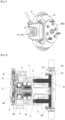
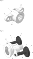
- the invention relates to a disc brake F comprising a caliper E intended to span a sector of a disc D which is integral with a vehicle wheel, for example on the hub MO.
- This caliper E comprises two branches B1, B2 defining between them a space E1 in which brake pads P1, P2 extend opposite each other, intended to be located on either side of the disc sector.
- One branch of the caliper B1 also called the nose of the caliper E, carries the brake pad called fixed P1 relative to the caliper E while the second branch B2 carries the brake pad called mobile P2 relative to the caliper E and the mechanism for actuating the mobile brake pad.
- Branch B2 thus comprises a through bore defining a housing L in which is housed as an actuating mechanism a screw/nut system actuated by a geared motor.
- This geared motor is here entirely coaxial with the screw, and located entirely behind the screw, that is to say on the side opposite the brake pads with respect to the thread of the screw, which can thus be made in a solid part and without an internal bore.
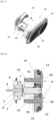
- This screw/nut system is preferably made up of a screw/ball nut assembly, comprising a screw 1, a nut 2 and balls 3 engaged in threads of the screw 1 and the nut 2.
- This ball nut operates here by recirculating the balls in the thickness of the nut, here in a path radially open towards the outside and covered by a ring, and the ends of which are delimited by pins inserted radially into the nut.
- the screw 1 and the nut 2 extend into the housing L.
- the screw 1 is mounted to be driven in rotation under the effect of the geared motor and fixed in translation while the nut 2 is mounted fixed in rotation in said housing L and movable in translation in said housing L under the effect of the rotational drive of the screw 1.
- Means for transmitting the rotational movement of a motor pinion 5 allow the rotational drive of the screw 1 and are for example successively constituted, from the motor shaft 4, of a motor pinion 5 forming a planetary gear, a planet carrier 61, a fixed crown 6 and a movable crown 7.
- the movable crown 7 is integral with the screw 1.
- this crown 7 is made in one piece with the screw 1, for example by constituting the end of the screw 1.
- the satellite pinions 8 located radially between the planet carrier 61 and the movable crown 7 ensure the irreversibility of the movements transmitted inside the brake F.
- the motor pinion 5 is fixed to the motor shaft 4, and the planet carrier 61 meshes with the motor pinion 5 as well as the movable crown 7 by planet pinions 8.
- the screw 1 is fixed to the movable crown 7.
- the nut 2 is in the form of a cylindrical sleeve 21 surrounding the screw 1, and carrying two projecting ears 22, for example diametrically opposed or placed on either side of the sleeve 21 in mirror symmetry.
- the housing L is thus of complementary shape and dimensions to the nut 2 mounted on the screw 1, having a bore and two grooves R at the periphery of the bore so that the nut 2 is fixed in translation in the housing L of the stirrup E, due to the ears 22 engaged in the grooves R of complementary shapes and dimensions and only drivable in translation in said housing L under the effect of the rotation of the screw 1.
- the branch B2 further comprises fixing orifices FI for the branch B1.
- the nut 2 carries two pistons 9 which respectively comprise a rod 91, one end of which is fixed to an ear 22 of the nut 1 and the other end of which carries the head of the piston 92. This latter end of the rod 91 is also engaged through an orifice O provided at the end of each groove R.
- the rod 91 of the pistons 9 is also engaged in a through orifice 11 provided in a sealing bellows 10.
- This sealing bellows 10 is intended to be placed at the end of the housing L of the caliper 2 to seal said housing L, with the piston heads 92 projecting into the space E1 between the branches B1, B2 of the caliper E as can be seen in the figure. figure 9 .
- This sealing bellows 10 has a flat central part 12 made rigid using a metal insert, and in which through orifices 11 are provided, this central part 12 being surrounded by a skirt 13, in particular folded in the shape of an accordion, in a closing element 15 in the form of a metal plate comprising passage orifices for the rods 91 of the pistons 9, the plate 15 having dimensions and a shape allowing forcible engagement in the end of the housing L (as can be seen figure 8 ).
- the skirt 13 of the sealing bellows 10 is fixed, also folded in an accordion shape, in a fixing groove at the periphery of the end of the housing L, as can be seen in Figure 2 .
- the sealing bellows 10 also has flexible accordion-shaped parts, fixed between the periphery of the through hole 11 of the sealing bellows 10 and the head 92 of a piston 9, making it possible to guarantee the sealing of the housing L during the movement of the pistons 9.
- the sealing bellows 10 is thus mounted in a sealed manner at the end of the housing L with the two piston heads 92 intended to protrude into the space E1 between the branches B1, B2 of the caliper E, the deployment of the accordion-folded parts maintaining the fixing and the seal.
- the nut 2 In the opposite direction to the rotation of the screw 1, the nut 2 is driven in translation backwards in the housing L, causing the pistons 9 to withdraw, which separates the movable plate P2 from the fixed plate P1 in the direction of loosening.
- the bore has a larger diameter in which the means for transmitting the rotational movement of the motor pinion 5 to the screw 1 are housed, such as a planet carrier 61, a fixed crown 6 and a movable crown 7.
- This movable crown 7 is therefore integral with the screw 1. As can be seen in Figure 3 , this movable crown 7 constitutes the end of the screw 1.
- the through bore is made in the branch B2 of the caliper E to form the housing L opening into the space E1 between said branch B2 and the branch B1.
- the screw/nut system is mounted in said housing, with a piston 9 connected to the nut 2, extending between each ear 22 of the nut 2 and the sealing bellows 10, mounted at the end of the housing L.
- the means for transmitting the rotational movement are mounted at the end of the bore, the end of the screw 1 in the form of a crown 7 being connected to the planet carrier 61 which is engaged with the motor pinion 5, the latter then being connected to the motor shaft 4 of an electric motor M, mounted in a housing B fixed on the bracket E at the outlet of the housing L and closed using a protective cover C.
- each rod 91 of piston 9 being fixed in an orifice of an ear 22 of nut 2, it is possible to adjust the position of this fixing to offset one of the piston heads relative to the other, which makes it possible to adjust the axial thrust stroke of each piston head 92 relative to the movable brake pad. As a result, it is possible to compensate for a difference in axial thrust and therefore a risk of wear of the lining of the brake pad.
- the brake pad linings have a material removal on a portion of said lining, thus allowing attenuation of the noise of the pad on the disc.
Landscapes
- Engineering & Computer Science (AREA)
- General Engineering & Computer Science (AREA)
- Mechanical Engineering (AREA)
- Transportation (AREA)
- Braking Arrangements (AREA)
Applications Claiming Priority (1)
| Application Number | Priority Date | Filing Date | Title |
|---|---|---|---|
| FR2313086A FR3155874B1 (fr) | 2023-11-27 | 2023-11-27 | Frein à disque, notamment pour véhicule automobile |
Publications (1)
| Publication Number | Publication Date |
|---|---|
| EP4559767A1 true EP4559767A1 (de) | 2025-05-28 |
Family
ID=89833969
Family Applications (1)
| Application Number | Title | Priority Date | Filing Date |
|---|---|---|---|
| EP24215588.5A Pending EP4559767A1 (de) | 2023-11-27 | 2024-11-26 | Scheibenbremse, insbesondere für ein kraftfahrzeug |
Country Status (2)
| Country | Link |
|---|---|
| EP (1) | EP4559767A1 (de) |
| FR (1) | FR3155874B1 (de) |
Citations (5)
| Publication number | Priority date | Publication date | Assignee | Title |
|---|---|---|---|---|
| DE102009013005B3 (de) * | 2009-03-13 | 2010-08-12 | Knorr-Bremse Systeme für Nutzfahrzeuge GmbH | Doppelkolben-Scheibenbremse |
| US20210222746A1 (en) * | 2020-01-22 | 2021-07-22 | Mando Corporation | Friction brake system for a vehicle |
| US20210310530A1 (en) * | 2020-04-03 | 2021-10-07 | Mando Corporation | Electro-mechanical brake |
| FR3116576A1 (fr) | 2020-11-20 | 2022-05-27 | Foundation Brakes France | Frein équipé d’une pièce de guidage d’une vis à billes déplaçant une plaquette de freinage |
| US11554766B2 (en) * | 2021-03-17 | 2023-01-17 | ZF Active Safety US Inc. | Hydraulically assisted electric parking brake |
-
2023
- 2023-11-27 FR FR2313086A patent/FR3155874B1/fr active Active
-
2024
- 2024-11-26 EP EP24215588.5A patent/EP4559767A1/de active Pending
Patent Citations (5)
| Publication number | Priority date | Publication date | Assignee | Title |
|---|---|---|---|---|
| DE102009013005B3 (de) * | 2009-03-13 | 2010-08-12 | Knorr-Bremse Systeme für Nutzfahrzeuge GmbH | Doppelkolben-Scheibenbremse |
| US20210222746A1 (en) * | 2020-01-22 | 2021-07-22 | Mando Corporation | Friction brake system for a vehicle |
| US20210310530A1 (en) * | 2020-04-03 | 2021-10-07 | Mando Corporation | Electro-mechanical brake |
| FR3116576A1 (fr) | 2020-11-20 | 2022-05-27 | Foundation Brakes France | Frein équipé d’une pièce de guidage d’une vis à billes déplaçant une plaquette de freinage |
| US11554766B2 (en) * | 2021-03-17 | 2023-01-17 | ZF Active Safety US Inc. | Hydraulically assisted electric parking brake |
Also Published As
| Publication number | Publication date |
|---|---|
| FR3155874A1 (fr) | 2025-05-30 |
| FR3155874B1 (fr) | 2026-01-30 |
Similar Documents
| Publication | Publication Date | Title |
|---|---|---|
| EP3676144B1 (de) | Elektromechanisches bremssattel mit zwei aktuatoren, die für ungleichmässigen bremsbelagverschleiss kompensiert | |
| EP3089901B1 (de) | Planetenreduktionsgetriebe, trommel- und scheibenbremse und bremsvorrichtung mit so einem planetenreduktionsgetriebe | |
| EP2935945B1 (de) | Planetenträger für einen elektromechanischen aktuator einer parkbremse, aktuator und montageverfahren | |
| EP3864314B1 (de) | Scheibenbremse mit ausgeglichener verteilung der durch einen kolben auf mindestens einen bremsbelag aufgebrachten schubkräfte | |
| EP2649341B1 (de) | Scheibenbremse mit verriegelungselement zur verriegelung des umsetzungseinsatzes mit einer verriegelung | |
| WO2015101611A2 (fr) | Actionneur entraine par pignon a glissiere axiale, et frein a tambour et dispositif de freinage ainsi equipes | |
| EP3175146B1 (de) | Drehmomentuntersetzungsgetriebe | |
| WO2016092029A1 (fr) | Actionneur electrique pour levier de frein de parking au sein d'un frein a tambour | |
| EP2652352B1 (de) | Scheibenbremse mit einer bewegungsumwandlungspatrone | |
| EP1352181A1 (de) | Elektromechanische betätigungseinrichtung einer mehrscheibenbremse für transportmittel, insbesondere für flugzeuge | |
| EP3440372B1 (de) | Elektromagnetischer bremssattel mit einer kolbenführung mit verringerter reibung | |
| EP3175136B1 (de) | Fahrzeugbremsenbetätiger | |
| FR3016013A1 (fr) | Actionneur de frein a tambour avec motorisation par emboitement a jeu angulaire | |
| EP3089900B1 (de) | Getriebeuntersetzung mit elektromotor für eine trommelbremse | |
| EP4559767A1 (de) | Scheibenbremse, insbesondere für ein kraftfahrzeug | |
| FR2949739A1 (fr) | Piston d'actionneur de servofrein et servofrein equipe d'un tel piston. | |
| EP1715564A2 (de) | Bremsvorrichtung für die Drehwelle eines Antriebs, wie ein Elektromotor | |
| WO2025078665A1 (fr) | Frein à disque, notamment pour véhicule automobile | |
| FR3155875A1 (fr) | Frein à disque, notamment pour véhicule automobile | |
| FR3162810A1 (fr) | Dispositif pour frein à étrier comprenant un anneau d’étanchéité emmanché sur une tête de poussée | |
| FR2813580A1 (fr) | Dispositif de freinage pour une roue d'avion | |
| FR3097021A1 (fr) | Reducteur et motoreducteur pour frein a débrayage intégré |
Legal Events
| Date | Code | Title | Description |
|---|---|---|---|
| PUAI | Public reference made under article 153(3) epc to a published international application that has entered the european phase |
Free format text: ORIGINAL CODE: 0009012 |
|
| STAA | Information on the status of an ep patent application or granted ep patent |
Free format text: STATUS: THE APPLICATION HAS BEEN PUBLISHED |
|
| AK | Designated contracting states |
Kind code of ref document: A1 Designated state(s): AL AT BE BG CH CY CZ DE DK EE ES FI FR GB GR HR HU IE IS IT LI LT LU LV MC ME MK MT NL NO PL PT RO RS SE SI SK SM TR |
|
| STAA | Information on the status of an ep patent application or granted ep patent |
Free format text: STATUS: REQUEST FOR EXAMINATION WAS MADE |
|
| 17P | Request for examination filed |
Effective date: 20251114 |