EP3865366A1 - Wagen eines öffentlichen transportfahrzeugs, insbesondere eines schienenfahrzeugs, und entsprechendes verfahren zu seiner ausstattung - Google Patents
Wagen eines öffentlichen transportfahrzeugs, insbesondere eines schienenfahrzeugs, und entsprechendes verfahren zu seiner ausstattung Download PDFInfo
- Publication number
- EP3865366A1 EP3865366A1 EP21157111.2A EP21157111A EP3865366A1 EP 3865366 A1 EP3865366 A1 EP 3865366A1 EP 21157111 A EP21157111 A EP 21157111A EP 3865366 A1 EP3865366 A1 EP 3865366A1
- Authority
- EP
- European Patent Office
- Prior art keywords
- car
- support structure
- reception room
- partition
- floor
- Prior art date
- Legal status (The legal status is an assumption and is not a legal conclusion. Google has not performed a legal analysis and makes no representation as to the accuracy of the status listed.)
- Granted
Links
Images


Classifications
-
- B—PERFORMING OPERATIONS; TRANSPORTING
- B61—RAILWAYS
- B61D—BODY DETAILS OR KINDS OF RAILWAY VEHICLES
- B61D17/00—Construction details of vehicle bodies
- B61D17/04—Construction details of vehicle bodies with bodies of metal; with composite, e.g. metal and wood body structures
- B61D17/048—Interior walls, e.g. separation walls between compartments
-
- B—PERFORMING OPERATIONS; TRANSPORTING
- B61—RAILWAYS
- B61D—BODY DETAILS OR KINDS OF RAILWAY VEHICLES
- B61D19/00—Door arrangements specially adapted for rail vehicles
- B61D19/003—Door arrangements specially adapted for rail vehicles characterised by the movements of the door
- B61D19/005—Door arrangements specially adapted for rail vehicles characterised by the movements of the door sliding
Definitions
- the present invention relates to a modular car for a public transport vehicle, in particular a rail vehicle.
- a public transport vehicle car usually has at least one reception room for passengers, this reception room being in particular delimited by side walls, a ceiling and a floor.
- cars are intended primarily for families accompanied by one or more children. Children have the opportunity to play together without risking disturbing other travelers. Other cars are for example dedicated to professionals by offering them a calm environment to work. Different services are therefore likely to be offered depending on the car.
- the object of the present invention is in particular to remedy this drawback by proposing a vehicle car, in particular a rail vehicle, having great flexibility of layout in order to easily and quickly adapt to the needs of the passengers.
- the separation device creates distinct spaces capable of being dedicated to different audiences and / or to different uses.
- the separation device is easily and quickly removable and thus offers great flexibility in the arrangement of the car.
- the subject of the invention is also a method of fitting out a car for a public transport vehicle of the aforementioned type, in particular a rail vehicle, comprising the following steps: removably mounting each partition on the support structure, and - removable mounting of the panel on the support structure, the method advantageously comprising a prior step of removably fixing the support structure to the ceiling, to the floor and to at least one side wall, preferably by screwing.
- a car 10 of a public transport vehicle is for example a railway vehicle, in particular a train, a metro or a tram.
- the vehicle is a bus.
- Car 10 is for example a two-story car, comprising a lower floor (not shown) and an upper floor 12. As a variant, the car 10 has only one floor. In the case where the car has only one stage, this is similar to stage 12 described in the present description.
- the floor 12 defines a reception room 14 extending lengthwise in a longitudinal direction X between a front face and a rear face (not shown).
- the reception room 14 is in particular delimited by a first side wall 16, a second side wall (not visible) facing the first side wall 16 in a transverse direction Y perpendicular to the longitudinal direction X, a floor 20 and a ceiling 22 facing the floor 20 in an elevation direction Z perpendicular to the longitudinal X and transverse Y directions.
- a covering is installed on the side walls 16, the floor 20 and the ceiling 22.
- At least one insert 24 is integrated into one of the floor 20, the ceiling 22 and the side walls 16.
- the insert 24 is for example a metal insert defining a threaded bore intended to receive a complementary screw.
- a plurality of inserts 24 are provided in the floor 20, the ceiling 22 and the side walls 16. When the inserts 24 do not receive screws, they are advantageously masked by means of caps, for example rubber caps. .
- the reception room comprises a plurality of groups of inserts 24 integrated into the ceiling 22, the floor 20 and at least one side wall 16, the different groups being distributed in successive positions along the length of the room. reception.
- the reception room 14 is intended to receive passengers and / or goods.
- the reception room 14 When the reception room 14 is intended to accommodate passengers, it typically comprises a plurality of seats (not shown) extending in rows in the transverse direction Y, each seat comprising a seat and a backrest.
- the floor 20 carries a corridor (not shown) extending lengthwise in the longitudinal direction X.
- the corridor is bordered on either side in the transverse direction Y by a first set of seats and a second set of seats. seats.
- the reception room 14 preferably includes luggage racks configured to receive suitcases or other luggage from passengers.
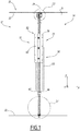
- the reception room 14 can be converted between an open configuration (not shown) and a compartmentalized configuration, shown in the figure. figure 1 .
- the reception room 14 defines a single reception space with no separation between the front face and the rear face.
- the open configuration is particularly suitable for accommodating the same type of passengers in a reception room 14.
- the reception room 14 defines several successive reception areas extending between the front face and the rear face of the reception room 14.
- the compartmentalized configuration is particularly suitable for accommodating in a reception room. several types of passengers.
- the car 10 comprises at least one separation device 30 mounted inside the reception room 14.
- the separation device 30 separates a first zone 32 of the reception room 14 from a second zone 34 of the reception room 14.
- the first zone 32 defines a zone called “business zone” intended for professionals and the second zone 34 defines a so-called “leisure zone”, for example intended for families with child (ren).
- the first and second zones 32, 34 have for example the same length and are intended to accommodate substantially the same number of passengers. As a variant, one of the first and second zones 32, 34 is larger and is able to accommodate more passengers than the other.
- the separation device 30 extends between the first and the second side walls 16 in the transverse direction Y and between the floor 20 and the ceiling 22 in the direction of elevation Z.
- the separation device 30 is arranged between two rows of seats.
- the separation device 30 is bordered on either side by the backrests of the seats of a first row and by the backs of the seats of a second row.
- the separation device 30 is removable.
- the term “removable” is understood to mean that the separation device 30 is capable of being assembled and disassembled several times during the commercial life of the vehicle.
- the separation device 30 is able to be assembled and disassembled when the various equipment of the reception room 14, in particular the seats and the luggage racks, and the coverings of the side walls 16, 18, floor 20 and ceiling 22 are already installed.
- the separation device 30 comprises at least one support structure 40, at least one partition 42, 43, removably mounted on the support structure 40 and defining a through opening 44 between the first and the second zones 32, 34, and a sliding panel 46 configured to slide on the support structure 40 between a plurality of positions, including a closed position, shown in FIG. figure 2 , in which the panel 46 completely closes the through opening 44 and thus prevents communication between the first and the second zones 32, 34.
- the support structure 40 secures the separation device 30 to the ceiling 22, to the floor 20 and to at least one of the side walls 16, preferably to the two side walls 16.
- the support structure 40 is preferably removably attached to the ceiling 22, to the floor 20 and to the side wall (s) 16.
- the support structure 40 is screwed to the ceiling 22, to the floor 20 and to the side wall (s) 16 by means of screws 48 screwed inside the inserts 24.
- the support structure 40 comprises two side supports 50 removably attached to a respective side wall 16, an upper support 52 removably attached to the ceiling 22 and a lower support 54 removably attached to the floor 20.
- Each side support 50 comprises a plate 56 and a guide 58 projecting from the plate 56.
- the plate 56 extends substantially parallel to the side walls 50, 52 and has holes 60 for screw passages 48.
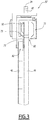
- the figure 3 shows an enlarged side view of the upper support 52.
- the upper support 52 comprises a transverse groove 70 and a guide 72 both extending substantially in the transverse direction Y when the reception room 14 is in a compartmentalized configuration.
- the guide 72 comprises a rail 73 extending substantially in the transverse direction Y.
- the figure 4 shows an enlarged side view of the lower support 54.
- the lower support 54 comprises a guide 74 extending substantially in the transverse direction Y.
- the lower support 54 is advantageously discontinuous.
- the guide 74 comprises two parts extending on either side of the through opening 44, in order to prevent a passenger from tripping over the guide 74 while passing from an area 32 of the reception room 14 to another zone 34 of the reception room.
- the guide 74 defines two transverse grooves 75, 76 substantially parallel and extending substantially in the transverse direction Y.
- the guide 74 has at its bottom holes for screw passages 48 so as to secure the lower support 54 to the floor 20.
- the separation device 30 comprises a first partition 42 and a second partition 43 extending on either side of the corridor and defining between them the through opening 44.
- the through opening 44 defines a passage having a width substantially equal to the width of the corridor, said widths being measured in the transverse direction Y.
- Each partition 42, 43 extends, in the direction of elevation Z, between an upper edge 80 and a lower edge 81 and, in the transverse direction Y, between a lateral edge 82 and a free edge 83.
- the free edge 83. of each partition 42, 43 at least partially delimits the through opening 44.
- each partition 42, 43 is respectively mounted on the upper support 54, the lower support 52 and a side support 50.
- the upper edge 80 is received in the transverse groove 70 of the upper support 52
- the lower edge 81 is received inside the guide 74 of the lower support 54, for example in the first groove 75
- the side edge 82 is received inside the guide 58 of a side support 50.
- each partition 42, 43 is removably mounted on the support 40, for example by means of screws or glue.
- Each partition 42, 43 is preferably made at least partly of glass, preferably of tempered glass, so that one zone is visible from the other zone through the partitions 42, 43.
- the panel 46 has a substantially rectangular shape and extends in the transverse direction Y between two side edges 86 and in the direction of elevation Z between an upper edge 88 and a lower edge 90.
- the panel 46 is received inside the guide 72 of the upper support 52.
- the upper edge 88 of the panel 46 comprises a bearing 92, for example a ball bearing, able to cooperate with the rail 73 of the upper support 52.
- the panel 46 is thus suspended on the rail 73 and is able to slide along the said rail 73.
- the lower edge 90 of the panel 46 is preferably received inside the second groove 76 of the lower support 54 and is able to slide in said groove 76.
- the panel 46 is slightly suspended, so that the lower edge 90 is not in contact with the bottom of the groove 76, which limits friction and facilitates the sliding of the panel 46.
- the panel 46 is able to slide in the transverse direction Y between two end positions, including the closed position (shown in figure 2 ) and an extreme open position.
- the through opening 44 is completely clear.
- the separation device 30 further comprises at least one stop system (not shown), one of the side edges 86 of the panel 46 abutting against said stop system in the extreme open position.
- the sliding panel 46 is made at least partly of glass, preferably of tempered glass, so that one can see through the panel 46.
- a handle 100 is mounted on each side of the panel 46, to facilitate opening and closing.
- the separation device 30 thus separates the reception room 14 into two successive reception areas capable of being isolated from each other by closing the sliding panel 46.
- the reception room 14 of the car 10 is in an open configuration. It defines a single reception area with no separation between the front face and the rear face.
- the separation device 30 is mounted in the car 10.
- the separation device 30 is arranged between two rows of seats, so as to be bordered. on either side by the backrests of the first row seats and by the backrests of the second row seats.
- the support structure 40 is mounted on the car 10, preferably between two rows of seats.
- the side supports 50, the upper support 52 and the lower support 54 are respectively removably attached to the side walls 16, to the ceiling 22 and to the floor 20.
- the support structure 40 is mounted by screwing the supports 50, 52. , 54 in the inserts 24.
- the partitions 42, 43 are removably mounted on the support structure 40, for example by screwing.
- the sliding panel 46 is removably mounted on the support structure 40.
- the bearing 92 of the panel 46 is mounted on the rail 73 of the upper support 52.
- the reception room 4 is then in a compartmentalized configuration.
- the sliding of the panel 46 in the transverse direction Y makes it possible to isolate a first zone 32 of the reception room 14 from a second zone 34 of the reception room 14 by closing the through opening 44.
- the mounting of the support structure 40, of the partitions 42, 43 and of the sliding panel 46 is advantageously carried out when the car 10 is already equipped, in particular when the various equipment of the reception room 14, in particular the seats and the carriers. luggage, and the coverings of the side walls 16, 18, floor 20 and ceiling 22 are already installed.
- the fitting process therefore does not require the removal of seats or the dismantling of other equipment in order to be able to install the separation device 30.
- the partitions 42, 43 and / or the panel 46 are mounted on the support structure 40 prior to the assembly of said structure 40 in the car 10.
- the separation device 30 comprises a single partition in which a through opening 44 is formed.
- the corridor is bordered on one side by a seat assembly and on the other side by one of the side walls 16.
- the separation device 30 comprises a single partition 42, 43 and the through opening. 44 extends between the free edge 83 of said partition 42, 43 and said side wall 16 of the car 10.
- the car 10 comprises, in a compartmentalized configuration, several separation devices 30 mounted inside the reception room 14.
- the reception room 14 can thus be separated into more than two zones 32. , 34, for example in three zones.
- the separation device 30 creates distinct spaces capable of being dedicated to different audiences and / or to different uses.
- the use of tempered glass ensures good sound insulation between the different spaces.
- the separation device 30 is easily and quickly removable.
- the installation of the separation device 30 is typically achievable in one hour by two operators. Car 10 can therefore be quickly rearranged between two journeys.
- the passage of the reception room 14 from an open configuration to a compartmentalized configuration is also reversible.
- the vehicle car 10 according to the invention thus exhibits great flexibility of layout and adapts easily and quickly to the needs of the operator of the vehicle.
Landscapes
- Engineering & Computer Science (AREA)
- Mechanical Engineering (AREA)
- Life Sciences & Earth Sciences (AREA)
- Wood Science & Technology (AREA)
- Body Structure For Vehicles (AREA)
- Fittings On The Vehicle Exterior For Carrying Loads, And Devices For Holding Or Mounting Articles (AREA)
- Vehicle Interior And Exterior Ornaments, Soundproofing, And Insulation (AREA)
- Vehicle Step Arrangements And Article Storage (AREA)
Applications Claiming Priority (1)
| Application Number | Priority Date | Filing Date | Title |
|---|---|---|---|
| FR2001556A FR3107243B1 (fr) | 2020-02-17 | 2020-02-17 | Voiture de véhicule de transport public, notamment de véhicule ferroviaire, et procédé d’aménagement associé |
Publications (2)
| Publication Number | Publication Date |
|---|---|
| EP3865366A1 true EP3865366A1 (de) | 2021-08-18 |
| EP3865366B1 EP3865366B1 (de) | 2023-02-15 |
Family
ID=70456970
Family Applications (1)
| Application Number | Title | Priority Date | Filing Date |
|---|---|---|---|
| EP21157111.2A Active EP3865366B1 (de) | 2020-02-17 | 2021-02-15 | Wagen eines öffentlichen transportfahrzeugs, insbesondere eines schienenfahrzeugs, und entsprechendes verfahren zu seiner ausstattung |
Country Status (3)
| Country | Link |
|---|---|
| EP (1) | EP3865366B1 (de) |
| ES (1) | ES2943541T3 (de) |
| FR (1) | FR3107243B1 (de) |
Cited By (3)
| Publication number | Priority date | Publication date | Assignee | Title |
|---|---|---|---|---|
| CN114228761A (zh) * | 2021-12-28 | 2022-03-25 | 中车成都机车车辆有限公司 | 一种车厢诊疗室墙体结构及具有该结构的医疗车厢 |
| EP4261096A1 (de) | 2022-04-12 | 2023-10-18 | ALSTOM Holdings | Fixierungssystem zum befestigen eines gegenstandes an einem fahrzeugboden und verfahren zum befestigen |
| FR3158675A1 (fr) * | 2024-01-25 | 2025-08-01 | Speedinnov | Porte de véhicule et véhicule correspondant |
Citations (7)
| Publication number | Priority date | Publication date | Assignee | Title |
|---|---|---|---|---|
| FR2102762A5 (de) * | 1970-08-20 | 1972-04-07 | Compin Ets | |
| JPS5079011A (de) * | 1973-11-15 | 1975-06-27 | ||
| US5309845A (en) * | 1991-02-05 | 1994-05-10 | Kawasaki Jukogyo Kabushiki Kaisha | Vehicle body |
| DE4300717A1 (de) * | 1993-01-14 | 1994-07-21 | Talbot Waggonfab | Inneneinrichtung für ein Schienenfahrzeug zur Personenbeförderung |
| JP2001171515A (ja) * | 1999-12-15 | 2001-06-26 | Kinki Sharyo Co Ltd | 鉄道車両の内妻仕切等の取付構造 |
| WO2012152523A1 (de) * | 2011-05-12 | 2012-11-15 | Siemens Ag Österreich | Schienenfahrzeuginnentür |
| WO2017190927A1 (de) * | 2016-05-02 | 2017-11-09 | Siemens Aktiengesellschaft | Fahrzeug für den öffentlichen personenverkehr |
-
2020
- 2020-02-17 FR FR2001556A patent/FR3107243B1/fr active Active
-
2021
- 2021-02-15 EP EP21157111.2A patent/EP3865366B1/de active Active
- 2021-02-15 ES ES21157111T patent/ES2943541T3/es active Active
Patent Citations (7)
| Publication number | Priority date | Publication date | Assignee | Title |
|---|---|---|---|---|
| FR2102762A5 (de) * | 1970-08-20 | 1972-04-07 | Compin Ets | |
| JPS5079011A (de) * | 1973-11-15 | 1975-06-27 | ||
| US5309845A (en) * | 1991-02-05 | 1994-05-10 | Kawasaki Jukogyo Kabushiki Kaisha | Vehicle body |
| DE4300717A1 (de) * | 1993-01-14 | 1994-07-21 | Talbot Waggonfab | Inneneinrichtung für ein Schienenfahrzeug zur Personenbeförderung |
| JP2001171515A (ja) * | 1999-12-15 | 2001-06-26 | Kinki Sharyo Co Ltd | 鉄道車両の内妻仕切等の取付構造 |
| WO2012152523A1 (de) * | 2011-05-12 | 2012-11-15 | Siemens Ag Österreich | Schienenfahrzeuginnentür |
| WO2017190927A1 (de) * | 2016-05-02 | 2017-11-09 | Siemens Aktiengesellschaft | Fahrzeug für den öffentlichen personenverkehr |
Cited By (4)
| Publication number | Priority date | Publication date | Assignee | Title |
|---|---|---|---|---|
| CN114228761A (zh) * | 2021-12-28 | 2022-03-25 | 中车成都机车车辆有限公司 | 一种车厢诊疗室墙体结构及具有该结构的医疗车厢 |
| CN114228761B (zh) * | 2021-12-28 | 2024-04-12 | 中车成都机车车辆有限公司 | 一种车厢诊疗室墙体结构及具有该结构的医疗车厢 |
| EP4261096A1 (de) | 2022-04-12 | 2023-10-18 | ALSTOM Holdings | Fixierungssystem zum befestigen eines gegenstandes an einem fahrzeugboden und verfahren zum befestigen |
| FR3158675A1 (fr) * | 2024-01-25 | 2025-08-01 | Speedinnov | Porte de véhicule et véhicule correspondant |
Also Published As
| Publication number | Publication date |
|---|---|
| ES2943541T3 (es) | 2023-06-14 |
| FR3107243A1 (fr) | 2021-08-20 |
| FR3107243B1 (fr) | 2024-04-12 |
| EP3865366B1 (de) | 2023-02-15 |
Similar Documents
| Publication | Publication Date | Title |
|---|---|---|
| EP3865366B1 (de) | Wagen eines öffentlichen transportfahrzeugs, insbesondere eines schienenfahrzeugs, und entsprechendes verfahren zu seiner ausstattung | |
| EP3601050B1 (de) | Anordnung aus einzelnen sitzen für passagiere eines flugzeugs | |
| EP3381803B1 (de) | Flugzeug mit einem bestimmten layout | |
| FR3066473A1 (fr) | Aeronef comprenant un meuble de rangement de bagages loge dans la concavite du bord d'attaque | |
| WO2004018290A1 (fr) | Amenagement interieur d'une cabine d'aeronef | |
| FR2833241A1 (fr) | Systeme de logement sous plancher refroidi par air pour des boites electriques de systeme pour passagers d'avion et similaire | |
| EP4077133A1 (de) | Passgiersitzanordnung | |
| EP3838743B1 (de) | Gesamtheit von leitungen für luftfahrzeug zur montage auf gleitschienen | |
| FR3122143A1 (fr) | caisse de véhicule, notamment ferroviaire, et véhicule comprenant une telle caisse | |
| EP3019401B1 (de) | Vorrichtung zur verbesserung des komforts von passagieren eines transportmittels ohne wechsel von dessen personenbeförderungskapazität | |
| EP1910165B1 (de) | Flugzeugkabinentrennwand | |
| EP4238818A1 (de) | Fahrzeugsitz mit beweglicher trennwand und entsprechendes fahrzeug | |
| EP3656607B1 (de) | Halterungsvorrichtung für komfortelement in einem fahrzeug | |
| EP3368396B1 (de) | Anordnung zur befestigung eines sitzes am unterboden eines kraftfahrzeuges | |
| WO2021032723A1 (fr) | Agencement de sièges passagers, notamment pour aéronefs | |
| FR3069847A1 (fr) | Aeronef presentant un module d'amenagement particulier | |
| EP4480751A1 (de) | System zur inneneinrichtung eines fahrzeugs, einrichtung zur einrichtung einer ladefläche eines fahrzeugs und fahrzeug | |
| EP2049392A1 (de) | Flugzeugbaugruppe und mit einer solchen baugruppe ausgestattetes flugzeug | |
| EP3831685B1 (de) | Sitz für schienenfahrzeuge | |
| EP2110292A1 (de) | Sitzgruppe für Schienenfahrzeug | |
| FR2998243A1 (fr) | Table a abattant(s), en particulier pour l'amenagement d'un vehicule de transport en commun | |
| FR3130241A1 (fr) | Voiture à deux niveaux pour véhicule ferroviaire et véhicule ferroviaire associé | |
| FR3158675A1 (fr) | Porte de véhicule et véhicule correspondant | |
| FR3122145A1 (fr) | Ensemble d’aménagement de véhicule, véhicule et procédé d’installation associés | |
| FR3129139A1 (fr) | Dispositif de séparation amovible notamment pour une cabine d'avion |
Legal Events
| Date | Code | Title | Description |
|---|---|---|---|
| PUAI | Public reference made under article 153(3) epc to a published international application that has entered the european phase |
Free format text: ORIGINAL CODE: 0009012 |
|
| STAA | Information on the status of an ep patent application or granted ep patent |
Free format text: STATUS: THE APPLICATION HAS BEEN PUBLISHED |
|
| STAA | Information on the status of an ep patent application or granted ep patent |
Free format text: STATUS: REQUEST FOR EXAMINATION WAS MADE |
|
| AK | Designated contracting states |
Kind code of ref document: A1 Designated state(s): AL AT BE BG CH CY CZ DE DK EE ES FI FR GB GR HR HU IE IS IT LI LT LU LV MC MK MT NL NO PL PT RO RS SE SI SK SM TR |
|
| 17P | Request for examination filed |
Effective date: 20210810 |
|
| RBV | Designated contracting states (corrected) |
Designated state(s): AL AT BE BG CH CY CZ DE DK EE ES FI FR GB GR HR HU IE IS IT LI LT LU LV MC MK MT NL NO PL PT RO RS SE SI SK SM TR |
|
| GRAP | Despatch of communication of intention to grant a patent |
Free format text: ORIGINAL CODE: EPIDOSNIGR1 |
|
| STAA | Information on the status of an ep patent application or granted ep patent |
Free format text: STATUS: GRANT OF PATENT IS INTENDED |
|
| INTG | Intention to grant announced |
Effective date: 20220830 |
|
| GRAS | Grant fee paid |
Free format text: ORIGINAL CODE: EPIDOSNIGR3 |
|
| GRAA | (expected) grant |
Free format text: ORIGINAL CODE: 0009210 |
|
| STAA | Information on the status of an ep patent application or granted ep patent |
Free format text: STATUS: THE PATENT HAS BEEN GRANTED |
|
| RIN1 | Information on inventor provided before grant (corrected) |
Inventor name: BERNARD, ALEXANDRE |
|
| AK | Designated contracting states |
Kind code of ref document: B1 Designated state(s): AL AT BE BG CH CY CZ DE DK EE ES FI FR GB GR HR HU IE IS IT LI LT LU LV MC MK MT NL NO PL PT RO RS SE SI SK SM TR |
|
| REG | Reference to a national code |
Ref country code: CH Ref legal event code: EP Ref country code: GB Ref legal event code: FG4D Free format text: NOT ENGLISH |
|
| REG | Reference to a national code |
Ref country code: DE Ref legal event code: R096 Ref document number: 602021001372 Country of ref document: DE |
|
| REG | Reference to a national code |
Ref country code: AT Ref legal event code: REF Ref document number: 1548105 Country of ref document: AT Kind code of ref document: T Effective date: 20230315 Ref country code: IE Ref legal event code: FG4D Free format text: LANGUAGE OF EP DOCUMENT: FRENCH |
|
| REG | Reference to a national code |
Ref country code: LT Ref legal event code: MG9D |
|
| REG | Reference to a national code |
Ref country code: ES Ref legal event code: FG2A Ref document number: 2943541 Country of ref document: ES Kind code of ref document: T3 Effective date: 20230614 |
|
| REG | Reference to a national code |
Ref country code: NL Ref legal event code: MP Effective date: 20230215 |
|
| REG | Reference to a national code |
Ref country code: AT Ref legal event code: MK05 Ref document number: 1548105 Country of ref document: AT Kind code of ref document: T Effective date: 20230215 |
|
| PG25 | Lapsed in a contracting state [announced via postgrant information from national office to epo] |
Ref country code: RS Free format text: LAPSE BECAUSE OF FAILURE TO SUBMIT A TRANSLATION OF THE DESCRIPTION OR TO PAY THE FEE WITHIN THE PRESCRIBED TIME-LIMIT Effective date: 20230215 Ref country code: PT Free format text: LAPSE BECAUSE OF FAILURE TO SUBMIT A TRANSLATION OF THE DESCRIPTION OR TO PAY THE FEE WITHIN THE PRESCRIBED TIME-LIMIT Effective date: 20230615 Ref country code: NO Free format text: LAPSE BECAUSE OF FAILURE TO SUBMIT A TRANSLATION OF THE DESCRIPTION OR TO PAY THE FEE WITHIN THE PRESCRIBED TIME-LIMIT Effective date: 20230515 Ref country code: NL Free format text: LAPSE BECAUSE OF FAILURE TO SUBMIT A TRANSLATION OF THE DESCRIPTION OR TO PAY THE FEE WITHIN THE PRESCRIBED TIME-LIMIT Effective date: 20230215 Ref country code: LV Free format text: LAPSE BECAUSE OF FAILURE TO SUBMIT A TRANSLATION OF THE DESCRIPTION OR TO PAY THE FEE WITHIN THE PRESCRIBED TIME-LIMIT Effective date: 20230215 Ref country code: LT Free format text: LAPSE BECAUSE OF FAILURE TO SUBMIT A TRANSLATION OF THE DESCRIPTION OR TO PAY THE FEE WITHIN THE PRESCRIBED TIME-LIMIT Effective date: 20230215 Ref country code: HR Free format text: LAPSE BECAUSE OF FAILURE TO SUBMIT A TRANSLATION OF THE DESCRIPTION OR TO PAY THE FEE WITHIN THE PRESCRIBED TIME-LIMIT Effective date: 20230215 Ref country code: AT Free format text: LAPSE BECAUSE OF FAILURE TO SUBMIT A TRANSLATION OF THE DESCRIPTION OR TO PAY THE FEE WITHIN THE PRESCRIBED TIME-LIMIT Effective date: 20230215 |
|
| PG25 | Lapsed in a contracting state [announced via postgrant information from national office to epo] |
Ref country code: SE Free format text: LAPSE BECAUSE OF FAILURE TO SUBMIT A TRANSLATION OF THE DESCRIPTION OR TO PAY THE FEE WITHIN THE PRESCRIBED TIME-LIMIT Effective date: 20230215 Ref country code: PL Free format text: LAPSE BECAUSE OF FAILURE TO SUBMIT A TRANSLATION OF THE DESCRIPTION OR TO PAY THE FEE WITHIN THE PRESCRIBED TIME-LIMIT Effective date: 20230215 Ref country code: IS Free format text: LAPSE BECAUSE OF FAILURE TO SUBMIT A TRANSLATION OF THE DESCRIPTION OR TO PAY THE FEE WITHIN THE PRESCRIBED TIME-LIMIT Effective date: 20230615 Ref country code: GR Free format text: LAPSE BECAUSE OF FAILURE TO SUBMIT A TRANSLATION OF THE DESCRIPTION OR TO PAY THE FEE WITHIN THE PRESCRIBED TIME-LIMIT Effective date: 20230516 Ref country code: FI Free format text: LAPSE BECAUSE OF FAILURE TO SUBMIT A TRANSLATION OF THE DESCRIPTION OR TO PAY THE FEE WITHIN THE PRESCRIBED TIME-LIMIT Effective date: 20230215 |
|
| REG | Reference to a national code |
Ref country code: BE Ref legal event code: MM Effective date: 20230228 |
|
| PG25 | Lapsed in a contracting state [announced via postgrant information from national office to epo] |
Ref country code: SM Free format text: LAPSE BECAUSE OF FAILURE TO SUBMIT A TRANSLATION OF THE DESCRIPTION OR TO PAY THE FEE WITHIN THE PRESCRIBED TIME-LIMIT Effective date: 20230215 Ref country code: RO Free format text: LAPSE BECAUSE OF FAILURE TO SUBMIT A TRANSLATION OF THE DESCRIPTION OR TO PAY THE FEE WITHIN THE PRESCRIBED TIME-LIMIT Effective date: 20230215 Ref country code: LU Free format text: LAPSE BECAUSE OF NON-PAYMENT OF DUE FEES Effective date: 20230215 Ref country code: EE Free format text: LAPSE BECAUSE OF FAILURE TO SUBMIT A TRANSLATION OF THE DESCRIPTION OR TO PAY THE FEE WITHIN THE PRESCRIBED TIME-LIMIT Effective date: 20230215 Ref country code: DK Free format text: LAPSE BECAUSE OF FAILURE TO SUBMIT A TRANSLATION OF THE DESCRIPTION OR TO PAY THE FEE WITHIN THE PRESCRIBED TIME-LIMIT Effective date: 20230215 Ref country code: CZ Free format text: LAPSE BECAUSE OF FAILURE TO SUBMIT A TRANSLATION OF THE DESCRIPTION OR TO PAY THE FEE WITHIN THE PRESCRIBED TIME-LIMIT Effective date: 20230215 |
|
| REG | Reference to a national code |
Ref country code: DE Ref legal event code: R097 Ref document number: 602021001372 Country of ref document: DE |
|
| P01 | Opt-out of the competence of the unified patent court (upc) registered |
Effective date: 20231025 |
|
| PG25 | Lapsed in a contracting state [announced via postgrant information from national office to epo] |
Ref country code: SK Free format text: LAPSE BECAUSE OF FAILURE TO SUBMIT A TRANSLATION OF THE DESCRIPTION OR TO PAY THE FEE WITHIN THE PRESCRIBED TIME-LIMIT Effective date: 20230215 |
|
| REG | Reference to a national code |
Ref country code: IE Ref legal event code: MM4A |
|
| PLBE | No opposition filed within time limit |
Free format text: ORIGINAL CODE: 0009261 |
|
| STAA | Information on the status of an ep patent application or granted ep patent |
Free format text: STATUS: NO OPPOSITION FILED WITHIN TIME LIMIT |
|
| PG25 | Lapsed in a contracting state [announced via postgrant information from national office to epo] |
Ref country code: MC Free format text: LAPSE BECAUSE OF FAILURE TO SUBMIT A TRANSLATION OF THE DESCRIPTION OR TO PAY THE FEE WITHIN THE PRESCRIBED TIME-LIMIT Effective date: 20230215 |
|
| 26N | No opposition filed |
Effective date: 20231116 |
|
| PG25 | Lapsed in a contracting state [announced via postgrant information from national office to epo] |
Ref country code: SI Free format text: LAPSE BECAUSE OF FAILURE TO SUBMIT A TRANSLATION OF THE DESCRIPTION OR TO PAY THE FEE WITHIN THE PRESCRIBED TIME-LIMIT Effective date: 20230215 Ref country code: MC Free format text: LAPSE BECAUSE OF FAILURE TO SUBMIT A TRANSLATION OF THE DESCRIPTION OR TO PAY THE FEE WITHIN THE PRESCRIBED TIME-LIMIT Effective date: 20230215 Ref country code: IE Free format text: LAPSE BECAUSE OF NON-PAYMENT OF DUE FEES Effective date: 20230215 |
|
| PG25 | Lapsed in a contracting state [announced via postgrant information from national office to epo] |
Ref country code: BE Free format text: LAPSE BECAUSE OF NON-PAYMENT OF DUE FEES Effective date: 20230228 |
|
| REG | Reference to a national code |
Ref country code: CH Ref legal event code: PL |
|
| PG25 | Lapsed in a contracting state [announced via postgrant information from national office to epo] |
Ref country code: CH Free format text: LAPSE BECAUSE OF NON-PAYMENT OF DUE FEES Effective date: 20240229 |
|
| PG25 | Lapsed in a contracting state [announced via postgrant information from national office to epo] |
Ref country code: CH Free format text: LAPSE BECAUSE OF NON-PAYMENT OF DUE FEES Effective date: 20240229 |
|
| PG25 | Lapsed in a contracting state [announced via postgrant information from national office to epo] |
Ref country code: BG Free format text: LAPSE BECAUSE OF FAILURE TO SUBMIT A TRANSLATION OF THE DESCRIPTION OR TO PAY THE FEE WITHIN THE PRESCRIBED TIME-LIMIT Effective date: 20230215 |
|
| PG25 | Lapsed in a contracting state [announced via postgrant information from national office to epo] |
Ref country code: BG Free format text: LAPSE BECAUSE OF FAILURE TO SUBMIT A TRANSLATION OF THE DESCRIPTION OR TO PAY THE FEE WITHIN THE PRESCRIBED TIME-LIMIT Effective date: 20230215 |
|
| PG25 | Lapsed in a contracting state [announced via postgrant information from national office to epo] |
Ref country code: CY Free format text: LAPSE BECAUSE OF FAILURE TO SUBMIT A TRANSLATION OF THE DESCRIPTION OR TO PAY THE FEE WITHIN THE PRESCRIBED TIME-LIMIT; INVALID AB INITIO Effective date: 20210215 |
|
| PG25 | Lapsed in a contracting state [announced via postgrant information from national office to epo] |
Ref country code: HU Free format text: LAPSE BECAUSE OF FAILURE TO SUBMIT A TRANSLATION OF THE DESCRIPTION OR TO PAY THE FEE WITHIN THE PRESCRIBED TIME-LIMIT; INVALID AB INITIO Effective date: 20210215 |
|
| GBPC | Gb: european patent ceased through non-payment of renewal fee |
Effective date: 20250215 |
|
| PG25 | Lapsed in a contracting state [announced via postgrant information from national office to epo] |
Ref country code: TR Free format text: LAPSE BECAUSE OF FAILURE TO SUBMIT A TRANSLATION OF THE DESCRIPTION OR TO PAY THE FEE WITHIN THE PRESCRIBED TIME-LIMIT Effective date: 20230215 |
|
| PG25 | Lapsed in a contracting state [announced via postgrant information from national office to epo] |
Ref country code: GB Free format text: LAPSE BECAUSE OF NON-PAYMENT OF DUE FEES Effective date: 20250215 |
|
| PGFP | Annual fee paid to national office [announced via postgrant information from national office to epo] |
Ref country code: DE Payment date: 20260218 Year of fee payment: 6 |
|
| PGFP | Annual fee paid to national office [announced via postgrant information from national office to epo] |
Ref country code: IT Payment date: 20260224 Year of fee payment: 6 |
|
| PGFP | Annual fee paid to national office [announced via postgrant information from national office to epo] |
Ref country code: FR Payment date: 20260218 Year of fee payment: 6 |
|
| PG25 | Lapsed in a contracting state [announced via postgrant information from national office to epo] |
Ref country code: CH Free format text: THE PATENT HAS BEEN ANNULLED BY A DECISION OF A NATIONAL AUTHORITY Effective date: 20240229 |
|
| PGFP | Annual fee paid to national office [announced via postgrant information from national office to epo] |
Ref country code: ES Payment date: 20260409 Year of fee payment: 6 |
|
| PG25 | Lapsed in a contracting state [announced via postgrant information from national office to epo] |
Ref country code: IT Free format text: LAPSE BECAUSE OF NON-PAYMENT OF DUE FEES Effective date: 20230215 |
|
| PG25 | Lapsed in a contracting state [announced via postgrant information from national office to epo] |
Ref country code: MT Free format text: LAPSE BECAUSE OF NON-PAYMENT OF DUE FEES Effective date: 20230215 |