EP3865685A1 - Centrale thermique à vapeur et procédé de conversion d'une centrale thermique à vapeur existante - Google Patents
Centrale thermique à vapeur et procédé de conversion d'une centrale thermique à vapeur existante Download PDFInfo
- Publication number
- EP3865685A1 EP3865685A1 EP20156798.9A EP20156798A EP3865685A1 EP 3865685 A1 EP3865685 A1 EP 3865685A1 EP 20156798 A EP20156798 A EP 20156798A EP 3865685 A1 EP3865685 A1 EP 3865685A1
- Authority
- EP
- European Patent Office
- Prior art keywords
- boiler
- power plant
- hot air
- steam power
- energy store
- Prior art date
- Legal status (The legal status is an assumption and is not a legal conclusion. Google has not performed a legal analysis and makes no representation as to the accuracy of the status listed.)
- Withdrawn
Links
Images
Classifications
-
- F—MECHANICAL ENGINEERING; LIGHTING; HEATING; WEAPONS; BLASTING
- F01—MACHINES OR ENGINES IN GENERAL; ENGINE PLANTS IN GENERAL; STEAM ENGINES
- F01K—STEAM ENGINE PLANTS; STEAM ACCUMULATORS; ENGINE PLANTS NOT OTHERWISE PROVIDED FOR; ENGINES USING SPECIAL WORKING FLUIDS OR CYCLES
- F01K3/00—Plants characterised by the use of steam or heat accumulators, or intermediate steam heaters, therein
- F01K3/18—Plants characterised by the use of steam or heat accumulators, or intermediate steam heaters, therein having heaters
- F01K3/20—Plants characterised by the use of steam or heat accumulators, or intermediate steam heaters, therein having heaters with heating by combustion gases of main boiler
-
- F—MECHANICAL ENGINEERING; LIGHTING; HEATING; WEAPONS; BLASTING
- F22—STEAM GENERATION
- F22B—METHODS OF STEAM GENERATION; STEAM BOILERS
- F22B31/00—Modifications of boiler construction, or of tube systems, dependent on installation of combustion apparatus; Arrangements or dispositions of combustion apparatus
- F22B31/0007—Modifications of boiler construction, or of tube systems, dependent on installation of combustion apparatus; Arrangements or dispositions of combustion apparatus with combustion in a fluidized bed
-
- F—MECHANICAL ENGINEERING; LIGHTING; HEATING; WEAPONS; BLASTING
- F22—STEAM GENERATION
- F22B—METHODS OF STEAM GENERATION; STEAM BOILERS
- F22B35/00—Control systems for steam boilers
-
- Y—GENERAL TAGGING OF NEW TECHNOLOGICAL DEVELOPMENTS; GENERAL TAGGING OF CROSS-SECTIONAL TECHNOLOGIES SPANNING OVER SEVERAL SECTIONS OF THE IPC; TECHNICAL SUBJECTS COVERED BY FORMER USPC CROSS-REFERENCE ART COLLECTIONS [XRACs] AND DIGESTS
- Y02—TECHNOLOGIES OR APPLICATIONS FOR MITIGATION OR ADAPTATION AGAINST CLIMATE CHANGE
- Y02E—REDUCTION OF GREENHOUSE GAS [GHG] EMISSIONS, RELATED TO ENERGY GENERATION, TRANSMISSION OR DISTRIBUTION
- Y02E60/00—Enabling technologies; Technologies with a potential or indirect contribution to GHG emissions mitigation
- Y02E60/14—Thermal energy storage
Definitions
- ETES electro-thermal energy storage
- Thermal energy storage systems are currently hardly commercially available in large power plants, or these energy storage systems are only planned as an additive system parallel to the existing cycle.
- An additional waste heat boiler (English Heat Recovery Steam Generator, or HRSG for short) is installed to transfer the stored heat into the water / steam cycle. This waste heat boiler is associated with considerable additional financial expense.
- the invention is based on the object of enabling an efficient and cost-effective integration of a thermal energy store in a steam power plant, in particular in an existing steam power plant.
- a steam power plant comprising a steam generating unit and a thermal energy store, the steam generating unit having a fossil-fired boiler with at least one hot air inlet, the energy store having an air inlet and an air outlet, and a hot air line being connected to the air outlet, which in the at least one hot air inlet of the boiler opens.
- the object is also achieved according to the invention by a method for converting a steam power plant by adding an already existing steam generating unit which is a fossil fuel Has boiler with at least one hot air inlet, is supplemented by a thermal energy store, the boiler being operated with hot air from the energy store.
- the invention is based on the consideration, so that an optimum is achieved both on the cost side and on the efficiency side, to propose a connection of the thermal energy store to an existing steam power plant, the integration of the energy store being designed in such a way that it is based on as many existing components as possible in the Power plant falls back.
- the additional investment costs must be kept to a minimum. It is particularly important to be able to continue using the relatively expensive boiler.
- Thermal energy is stored in the energy store using air as a carrier medium. When the energy storage device is discharged or discharged, the air is passed through the energy storage device, the air absorbing thermal energy from the energy storage device and this is then fed as hot air to the fossil-fueled boiler.
- the hot air stream has a temperature of over 700 ° C, in particular of approx. 800 ° C. Partial admixture of the hot air can gradually save fossil fuel for the boiler operation.
- the energy store is preferably a rock store.
- An electrothermal energy store (ETES) is based on the principle of a kind of "giant hair dryer” through which a stream of hot air is generated. This is done with the help of heating elements and a fan. The fan is designed in such a way that the pressure is sufficient to convey the air along the entire hot air path.
- ETES electrothermal energy store
- In charging mode excess electricity is taken from the power grid and converted into heat via resistance heating implemented. This heat is absorbed by an air stream and conducted as hot air to the stone storage tank. In the cold storage tank, the sensible heat in the air is transferred to the amount of rock. The cooled air is fed back to the heating elements in circulation mode via a fan. This charging process can continue until the storage tank has reached its final charging temperature.
- solar thermal storage can preferably take place, in which a solar tower power plant generates the hot air.
- the energy store is designed for operation without fuel supply, so that the boiler is operated exclusively with hot air from the energy store. This means that there is no firing process during operation, but the energy of the hot air from the thermal energy storage is sufficient to cover the energy requirements for operating the boiler. In this case, only the boiler's heat transfer surfaces are used.
- a closed air circuit is formed between the steam generating unit and the energy store, the hot air line being part of the closed air circuit.
- the boiler is a fluidized bed boiler.
- the fuel and the bed material are kept in suspension by the addition of a fluidization medium, in this case the hot air.
- the crushed fuel particles have a large surface so that good burnout can take place.
- a fluidized bed boiler is particularly suitable for use in the steam power plant described above suitable, since when operating this type of boiler with hot air at 700 ° C or more, as it is introduced into the boiler from the energy storage device, there is no need for firing or the addition of fuel.
- a particle filter is connected downstream of the fluidized bed boiler within the steam generation unit. This serves to intercept particles that are carried away by the air from the fluidized bed and which could damage the fan after the air flow has left the boiler.
- the boiler is a water tube boiler of the most varied of designs, such as tower boilers with continuous steam generation, drum boilers, boilers with grate firing, etc.
- a fuel inlet of the boiler is preferably connected to the hot air line. In this way, more air can flow into the boiler, so that overall there is a higher amount of air in the boiler, which enables the high temperature to be maintained and thus trouble-free operation of the boiler.
- a higher amount of hot air is advantageously fed into the boiler, in particular an amount of hot air increased by a factor of 2. This is particularly necessary when the boiler is operated without a firing process, but instead the thermal energy is only made available via the hot air from the energy store.
- additional hot air inlets are expediently attached to the boiler, through which the increased amount of hot air is conveyed into the boiler.
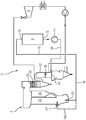
- FIG. 1 shows a steam power plant 2 with a steam generating unit 4 and a thermal energy store 6, which is designed as a rock store.
- the steam power plant 2 furthermore comprises a steam turbine 8, which is driven by means of steam from the steam generation unit 4.
- the steam power plant 2 shown is a converted steam power plant, which originally comprised the steam generating unit 4 and the steam turbine 8 and was subsequently supplemented by the rock storage facility 6 by integrating it into a closed air circuit.
- the fluidized bed boiler 22 is operated completely free of fuel. The entire thermal energy required is provided by the hot air flow. To make this possible, a higher air throughput than in the original, fossil-fired operation of the fluidized bed boiler 2 is required, in particular by a factor of 2 higher. This is achieved through structural measures to enlarge the air inlet 20, through the formation of new air inlets (for example by converting the original fuel inlet 24) and / or by increasing the pressure in the Hot air duct 18.
- the fluidized bed material is adapted to the new flow conditions in order to continue to ensure optimal heat transfer.
- a particle filter 30, shown symbolically here can be installed in the cyclone 26 of the fluidized bed boiler 22, e.g. in a downstream superheater 28 or a flue gas duct 32 with heat exchange surfaces, in order to intercept particles that are carried out of the fluidized bed by the air and are in the closed air- Circuit could reach the fan and damage it.
- a further modification in the area of the flue gas flue 32 ensures that a regenerative air preheater of the boiler 22 that is no longer required is shut off with a plate 34, for example, and is no longer flowed through.
- the air leaves the steam generation unit 4 via an air discharge line 36 in which the fan 14 is integrated and which opens into the air inlet 12 of the energy store 6.
- the air temperature is between 250 ° C and 400 ° C.
- the steam generated in the boiler 22 is fed to the steam turbine 8 and expanded.
- the mechanical / electrical energy released in the process can be fed into the network as a withdrawal service from the system.
Landscapes
- Engineering & Computer Science (AREA)
- Chemical & Material Sciences (AREA)
- Combustion & Propulsion (AREA)
- Mechanical Engineering (AREA)
- General Engineering & Computer Science (AREA)
- Physics & Mathematics (AREA)
- Thermal Sciences (AREA)
- Air Supply (AREA)
Priority Applications (2)
| Application Number | Priority Date | Filing Date | Title |
|---|---|---|---|
| EP20156798.9A EP3865685A1 (fr) | 2020-02-12 | 2020-02-12 | Centrale thermique à vapeur et procédé de conversion d'une centrale thermique à vapeur existante |
| PCT/EP2020/087367 WO2021160329A1 (fr) | 2020-02-12 | 2020-12-21 | Centrale à vapeur et procédé de conversion de centrale à vapeur existante |
Applications Claiming Priority (1)
| Application Number | Priority Date | Filing Date | Title |
|---|---|---|---|
| EP20156798.9A EP3865685A1 (fr) | 2020-02-12 | 2020-02-12 | Centrale thermique à vapeur et procédé de conversion d'une centrale thermique à vapeur existante |
Publications (1)
| Publication Number | Publication Date |
|---|---|
| EP3865685A1 true EP3865685A1 (fr) | 2021-08-18 |
Family
ID=69571905
Family Applications (1)
| Application Number | Title | Priority Date | Filing Date |
|---|---|---|---|
| EP20156798.9A Withdrawn EP3865685A1 (fr) | 2020-02-12 | 2020-02-12 | Centrale thermique à vapeur et procédé de conversion d'une centrale thermique à vapeur existante |
Country Status (2)
| Country | Link |
|---|---|
| EP (1) | EP3865685A1 (fr) |
| WO (1) | WO2021160329A1 (fr) |
Citations (3)
| Publication number | Priority date | Publication date | Assignee | Title |
|---|---|---|---|---|
| DE102012213976A1 (de) * | 2012-08-07 | 2014-02-13 | Siemens Aktiengesellschaft | Externer Dampfspeicher zur Beteiligung einer Dampfturbine an Netzdienstleistungen und Leistungsrampen |
| DE102014106300A1 (de) * | 2014-05-06 | 2015-11-12 | Deutsches Zentrum für Luft- und Raumfahrt e.V. | Dampfbereitstellungsvorrichtung und Verfahren zum Bereitstellen von Dampf |
| DE102016218379A1 (de) * | 2016-09-23 | 2018-03-29 | Deutsches Zentrum für Luft- und Raumfahrt e.V. | Pufferverfahren, Puffervorrichtung und Kraftwerk |
-
2020
- 2020-02-12 EP EP20156798.9A patent/EP3865685A1/fr not_active Withdrawn
- 2020-12-21 WO PCT/EP2020/087367 patent/WO2021160329A1/fr not_active Ceased
Patent Citations (3)
| Publication number | Priority date | Publication date | Assignee | Title |
|---|---|---|---|---|
| DE102012213976A1 (de) * | 2012-08-07 | 2014-02-13 | Siemens Aktiengesellschaft | Externer Dampfspeicher zur Beteiligung einer Dampfturbine an Netzdienstleistungen und Leistungsrampen |
| DE102014106300A1 (de) * | 2014-05-06 | 2015-11-12 | Deutsches Zentrum für Luft- und Raumfahrt e.V. | Dampfbereitstellungsvorrichtung und Verfahren zum Bereitstellen von Dampf |
| DE102016218379A1 (de) * | 2016-09-23 | 2018-03-29 | Deutsches Zentrum für Luft- und Raumfahrt e.V. | Pufferverfahren, Puffervorrichtung und Kraftwerk |
Also Published As
| Publication number | Publication date |
|---|---|
| WO2021160329A1 (fr) | 2021-08-19 |
Similar Documents
| Publication | Publication Date | Title |
|---|---|---|
| EP0558899B1 (fr) | Installation pour utiliser la chaleur des gaz sortant d'une chaudière chauffée au charbon | |
| EP1984624B1 (fr) | Méthode et dispositif pour augmenter la production énergétique dans une centrale thermique solaire | |
| EP0526816A1 (fr) | Centrale à turbines à gaz et à vapeur avec un générateur de vapeur solaire | |
| EP2167794B1 (fr) | Dispositif et procédé de production de force et de chaleur | |
| WO2021013389A1 (fr) | Turbine à gaz dotée d'un accumulateur d'énergie thermique, procédé de fonctionnement et procédé de modification | |
| DE4335216A1 (de) | Dampfkraftanlage zur Erzeugung elektrischer Energie | |
| DE102013210430B4 (de) | Energiespeichervorrichtung zur Vorwärmung von Speisewasser | |
| DE102009039055A1 (de) | Verfahren und Einrichtung zur Abscheidung von CO2 aus Abgas | |
| DE102009035062A1 (de) | Verfahren zum Betrieb eines Dampfturbinenkraftwerks sowie Einrichtung zur Erzeugung von Dampf | |
| DE4126036A1 (de) | Gas- und dampfturbinenkraftwerk mit einem solar beheizten dampferzeuger | |
| EP0530519B1 (fr) | Centrale électrique chauffée par l'énergie nucléaire et fossile | |
| AT518186B1 (de) | Wärmekraftwerk und Verfahren zum Speichern von Wärme | |
| EP2412943B1 (fr) | Dispositif et procédé de production de gaz chaud à l'aide d'un chauffage intégré d'un fluide caloporteur | |
| EP0098481B1 (fr) | Méthode pour générer de l'énergie électrique dans une centrale combinée à combustion en lit fluidisé | |
| EP1208294B1 (fr) | Procede et dispositif permettant d'augmenter la pression d'un gaz | |
| EP3865685A1 (fr) | Centrale thermique à vapeur et procédé de conversion d'une centrale thermique à vapeur existante | |
| DE102006029524B4 (de) | Stromgenerator/Wasserstoffgewinnungs-Kombinationsanlage | |
| DE4300192C2 (de) | Verfahren zum Betrieb von mindestens zwei miteinander verknüpften Abhitzeprozessen und Dampferzeugungsanlage zur Durchführung des Verfahrens | |
| DE4015104A1 (de) | Kombinierte waermekraftanlage | |
| DE4222811C1 (de) | Anordnung zur Nutzung der im Abgas eines kohlegefeuerten Kessels enthaltenen Wärme | |
| EP3857032B1 (fr) | Procédé d'exploitation d'une centrale électrique en vue de la production d'énergie électrique par combustion d'un combustible contenant du carbone et système correspondant d'exploitation d'une centrale électrique | |
| WO2011045213A1 (fr) | Adaptation de la température de préchauffage d'un circuit secondaire d'une centrale électrique par activation sélective de différents points de soutirage d'une turbine à vapeur | |
| EP0618404B1 (fr) | Procédé et installation pour la génération de vapeur dans une centrale de puissance et de chaleur | |
| DE3101051A1 (de) | "zwischenkreislauf fuer ein druckfliessbett" | |
| EP4288643B1 (fr) | Production d'énergie électrique à partir d'hydrogène et d'oxygène |
Legal Events
| Date | Code | Title | Description |
|---|---|---|---|
| PUAI | Public reference made under article 153(3) epc to a published international application that has entered the european phase |
Free format text: ORIGINAL CODE: 0009012 |
|
| STAA | Information on the status of an ep patent application or granted ep patent |
Free format text: STATUS: THE APPLICATION HAS BEEN PUBLISHED |
|
| AK | Designated contracting states |
Kind code of ref document: A1 Designated state(s): AL AT BE BG CH CY CZ DE DK EE ES FI FR GB GR HR HU IE IS IT LI LT LU LV MC MK MT NL NO PL PT RO RS SE SI SK SM TR |
|
| STAA | Information on the status of an ep patent application or granted ep patent |
Free format text: STATUS: THE APPLICATION IS DEEMED TO BE WITHDRAWN |
|
| 18D | Application deemed to be withdrawn |
Effective date: 20220219 |