EP3865723A1 - Wälzlager - Google Patents
Wälzlager Download PDFInfo
- Publication number
- EP3865723A1 EP3865723A1 EP21156100.6A EP21156100A EP3865723A1 EP 3865723 A1 EP3865723 A1 EP 3865723A1 EP 21156100 A EP21156100 A EP 21156100A EP 3865723 A1 EP3865723 A1 EP 3865723A1
- Authority
- EP
- European Patent Office
- Prior art keywords
- rolling bearing
- bearing according
- external
- frame
- encoder
- Prior art date
- Legal status (The legal status is an assumption and is not a legal conclusion. Google has not performed a legal analysis and makes no representation as to the accuracy of the status listed.)
- Withdrawn
Links
- 238000005096 rolling process Methods 0.000 claims abstract description 68
- 238000007789 sealing Methods 0.000 claims abstract description 57
- 238000004891 communication Methods 0.000 claims abstract description 5
- 230000002787 reinforcement Effects 0.000 claims description 14
- 238000006073 displacement reaction Methods 0.000 claims description 7
- 238000000034 method Methods 0.000 claims description 7
- 230000004323 axial length Effects 0.000 claims description 5
- 230000001419 dependent effect Effects 0.000 claims 1
- 239000011324 bead Substances 0.000 description 3
- 239000003344 environmental pollutant Substances 0.000 description 3
- 239000000314 lubricant Substances 0.000 description 3
- 231100000719 pollutant Toxicity 0.000 description 3
- 230000003068 static effect Effects 0.000 description 3
- 238000011109 contamination Methods 0.000 description 2
- 239000000806 elastomer Substances 0.000 description 2
- 229920001971 elastomer Polymers 0.000 description 2
- 239000000463 material Substances 0.000 description 2
- 239000011159 matrix material Substances 0.000 description 2
- 238000003825 pressing Methods 0.000 description 2
- 239000000725 suspension Substances 0.000 description 2
- 238000005452 bending Methods 0.000 description 1
- 239000006229 carbon black Substances 0.000 description 1
- 229920001577 copolymer Polymers 0.000 description 1
- 239000000945 filler Substances 0.000 description 1
- 229920002313 fluoropolymer Polymers 0.000 description 1
- 239000004811 fluoropolymer Substances 0.000 description 1
- 239000004519 grease Substances 0.000 description 1
- 230000003116 impacting effect Effects 0.000 description 1
- 238000005461 lubrication Methods 0.000 description 1
- 239000006249 magnetic particle Substances 0.000 description 1
- 238000005259 measurement Methods 0.000 description 1
- 239000007769 metal material Substances 0.000 description 1
- 229910001172 neodymium magnet Inorganic materials 0.000 description 1
- 239000002245 particle Substances 0.000 description 1
- 239000004033 plastic Substances 0.000 description 1
- 229920000058 polyacrylate Polymers 0.000 description 1
- 229910052761 rare earth metal Inorganic materials 0.000 description 1
- 150000002910 rare earth metals Chemical class 0.000 description 1
- 230000000284 resting effect Effects 0.000 description 1
- 239000010802 sludge Substances 0.000 description 1
- 229910000859 α-Fe Inorganic materials 0.000 description 1
Images


Classifications
-
- F—MECHANICAL ENGINEERING; LIGHTING; HEATING; WEAPONS; BLASTING
- F16—ENGINEERING ELEMENTS AND UNITS; GENERAL MEASURES FOR PRODUCING AND MAINTAINING EFFECTIVE FUNCTIONING OF MACHINES OR INSTALLATIONS; THERMAL INSULATION IN GENERAL
- F16C—SHAFTS; FLEXIBLE SHAFTS; ELEMENTS OR CRANKSHAFT MECHANISMS; ROTARY BODIES OTHER THAN GEARING ELEMENTS; BEARINGS
- F16C33/00—Parts of bearings; Special methods for making bearings or parts thereof
- F16C33/72—Sealings
- F16C33/76—Sealings of ball or roller bearings
- F16C33/78—Sealings of ball or roller bearings with a diaphragm, disc, or ring, with or without resilient members
- F16C33/7816—Details of the sealing or parts thereof, e.g. geometry, material
- F16C33/782—Details of the sealing or parts thereof, e.g. geometry, material of the sealing region
- F16C33/7823—Details of the sealing or parts thereof, e.g. geometry, material of the sealing region of sealing lips
-
- F—MECHANICAL ENGINEERING; LIGHTING; HEATING; WEAPONS; BLASTING
- F16—ENGINEERING ELEMENTS AND UNITS; GENERAL MEASURES FOR PRODUCING AND MAINTAINING EFFECTIVE FUNCTIONING OF MACHINES OR INSTALLATIONS; THERMAL INSULATION IN GENERAL
- F16C—SHAFTS; FLEXIBLE SHAFTS; ELEMENTS OR CRANKSHAFT MECHANISMS; ROTARY BODIES OTHER THAN GEARING ELEMENTS; BEARINGS
- F16C33/00—Parts of bearings; Special methods for making bearings or parts thereof
- F16C33/72—Sealings
- F16C33/76—Sealings of ball or roller bearings
- F16C33/78—Sealings of ball or roller bearings with a diaphragm, disc, or ring, with or without resilient members
- F16C33/7816—Details of the sealing or parts thereof, e.g. geometry, material
- F16C33/782—Details of the sealing or parts thereof, e.g. geometry, material of the sealing region
- F16C33/7826—Details of the sealing or parts thereof, e.g. geometry, material of the sealing region of the opposing surface cooperating with the seal, e.g. a shoulder surface of a bearing ring
-
- F—MECHANICAL ENGINEERING; LIGHTING; HEATING; WEAPONS; BLASTING
- F16—ENGINEERING ELEMENTS AND UNITS; GENERAL MEASURES FOR PRODUCING AND MAINTAINING EFFECTIVE FUNCTIONING OF MACHINES OR INSTALLATIONS; THERMAL INSULATION IN GENERAL
- F16C—SHAFTS; FLEXIBLE SHAFTS; ELEMENTS OR CRANKSHAFT MECHANISMS; ROTARY BODIES OTHER THAN GEARING ELEMENTS; BEARINGS
- F16C33/00—Parts of bearings; Special methods for making bearings or parts thereof
- F16C33/72—Sealings
- F16C33/76—Sealings of ball or roller bearings
- F16C33/78—Sealings of ball or roller bearings with a diaphragm, disc, or ring, with or without resilient members
- F16C33/7869—Sealings of ball or roller bearings with a diaphragm, disc, or ring, with or without resilient members mounted with a cylindrical portion to the inner surface of the outer race and having a radial portion extending inward
- F16C33/7879—Sealings of ball or roller bearings with a diaphragm, disc, or ring, with or without resilient members mounted with a cylindrical portion to the inner surface of the outer race and having a radial portion extending inward with a further sealing ring
- F16C33/7883—Sealings of ball or roller bearings with a diaphragm, disc, or ring, with or without resilient members mounted with a cylindrical portion to the inner surface of the outer race and having a radial portion extending inward with a further sealing ring mounted to the inner race and of generally L-shape, the two sealing rings defining a sealing with box-shaped cross-section
-
- F—MECHANICAL ENGINEERING; LIGHTING; HEATING; WEAPONS; BLASTING
- F16—ENGINEERING ELEMENTS AND UNITS; GENERAL MEASURES FOR PRODUCING AND MAINTAINING EFFECTIVE FUNCTIONING OF MACHINES OR INSTALLATIONS; THERMAL INSULATION IN GENERAL
- F16C—SHAFTS; FLEXIBLE SHAFTS; ELEMENTS OR CRANKSHAFT MECHANISMS; ROTARY BODIES OTHER THAN GEARING ELEMENTS; BEARINGS
- F16C41/00—Other accessories, e.g. devices integrated in the bearing not relating to the bearing function as such
- F16C41/007—Encoders, e.g. parts with a plurality of alternating magnetic poles
-
- F—MECHANICAL ENGINEERING; LIGHTING; HEATING; WEAPONS; BLASTING
- F16—ENGINEERING ELEMENTS AND UNITS; GENERAL MEASURES FOR PRODUCING AND MAINTAINING EFFECTIVE FUNCTIONING OF MACHINES OR INSTALLATIONS; THERMAL INSULATION IN GENERAL
- F16C—SHAFTS; FLEXIBLE SHAFTS; ELEMENTS OR CRANKSHAFT MECHANISMS; ROTARY BODIES OTHER THAN GEARING ELEMENTS; BEARINGS
- F16C43/00—Assembling bearings
- F16C43/04—Assembling rolling-contact bearings
- F16C43/045—Mounting or replacing seals
-
- F—MECHANICAL ENGINEERING; LIGHTING; HEATING; WEAPONS; BLASTING
- F16—ENGINEERING ELEMENTS AND UNITS; GENERAL MEASURES FOR PRODUCING AND MAINTAINING EFFECTIVE FUNCTIONING OF MACHINES OR INSTALLATIONS; THERMAL INSULATION IN GENERAL
- F16C—SHAFTS; FLEXIBLE SHAFTS; ELEMENTS OR CRANKSHAFT MECHANISMS; ROTARY BODIES OTHER THAN GEARING ELEMENTS; BEARINGS
- F16C19/00—Bearings with rolling contact, for exclusively rotary movement
- F16C19/02—Bearings with rolling contact, for exclusively rotary movement with bearing balls essentially of the same size in one or more circular rows
- F16C19/14—Bearings with rolling contact, for exclusively rotary movement with bearing balls essentially of the same size in one or more circular rows for both radial and axial load
- F16C19/18—Bearings with rolling contact, for exclusively rotary movement with bearing balls essentially of the same size in one or more circular rows for both radial and axial load with two or more rows of balls
- F16C19/181—Bearings with rolling contact, for exclusively rotary movement with bearing balls essentially of the same size in one or more circular rows for both radial and axial load with two or more rows of balls with angular contact
- F16C19/183—Bearings with rolling contact, for exclusively rotary movement with bearing balls essentially of the same size in one or more circular rows for both radial and axial load with two or more rows of balls with angular contact with two rows at opposite angles
- F16C19/184—Bearings with rolling contact, for exclusively rotary movement with bearing balls essentially of the same size in one or more circular rows for both radial and axial load with two or more rows of balls with angular contact with two rows at opposite angles in O-arrangement
-
- F—MECHANICAL ENGINEERING; LIGHTING; HEATING; WEAPONS; BLASTING
- F16—ENGINEERING ELEMENTS AND UNITS; GENERAL MEASURES FOR PRODUCING AND MAINTAINING EFFECTIVE FUNCTIONING OF MACHINES OR INSTALLATIONS; THERMAL INSULATION IN GENERAL
- F16C—SHAFTS; FLEXIBLE SHAFTS; ELEMENTS OR CRANKSHAFT MECHANISMS; ROTARY BODIES OTHER THAN GEARING ELEMENTS; BEARINGS
- F16C2233/00—Monitoring condition, e.g. temperature, load, vibration
-
- F—MECHANICAL ENGINEERING; LIGHTING; HEATING; WEAPONS; BLASTING
- F16—ENGINEERING ELEMENTS AND UNITS; GENERAL MEASURES FOR PRODUCING AND MAINTAINING EFFECTIVE FUNCTIONING OF MACHINES OR INSTALLATIONS; THERMAL INSULATION IN GENERAL
- F16C—SHAFTS; FLEXIBLE SHAFTS; ELEMENTS OR CRANKSHAFT MECHANISMS; ROTARY BODIES OTHER THAN GEARING ELEMENTS; BEARINGS
- F16C2326/00—Articles relating to transporting
- F16C2326/01—Parts of vehicles in general
- F16C2326/02—Wheel hubs or castors
Definitions
- the invention relates to a rolling bearing comprising two members, respectively inner and outer, and rolling bodies arranged in a rolling space formed between said members to allow their relative rotation about an axis, as well as a method of mounting them. a sealing device in one side of the annular space of such a rolling bearing.
- a bearing according to the invention allows the mounting of a driving or non-driving wheel of a motor vehicle, the inner member being rotating and comprising means for fixing the wheel while the outer member is fixed and comprises fixing means on a suspension element of the vehicle.
- At least one side of the bearing space can be equipped with a device for sealing.
- each of the sides of the rolling space can be equipped with a sealing device comprising two rigid frames respectively integral with a member, one of said frames being equipped with a sealing element comprising at least one lip in contact rubbing on a bearing surface of the other reinforcement.
- the reinforcements form between them an annular chamber in communication with, on the one hand, the rolling space via an internal opening and, on the other hand, with the outside via an external opening.
- the bearing can also be equipped with an encoder which is secured to the rotating member by being disposed on one side of the rolling space.
- an encoder which is secured to the rotating member by being disposed on one side of the rolling space.
- Such a bearing when it is equipped with a sensor system for speed of rotation, angular position and / or direction of rotation, can in particular be used for mounting a motor vehicle wheel which is provided with a system on-board anti-lock braking system for said wheel and / or overall chassis control.
- the information delivered by the encoder can then be used by a computer of such a system as well as by any other on-board system using the wheel speed measurement as input data.
- one of the sealing devices provided on one side of the rolling space, respectively, can be equipped with such an encoder, the other sealing device being devoid of such an encoder.
- the outer frame of the sealing device may have a central portion connected, on the one hand, to an inner portion for fixing to the corresponding member of the bearing and, on the other hand, to an outer portion delimiting the external opening, the encoder being associated on the external face of said central portion.
- the encoder also extends over the outer portion so that the geometry of the outer opening depends on that of the encoder, and more generally on the presence or absence of said encoder on the outer frame.
- the sealing performance of the device depends on the geometry of the encoder, and is in particular not the same when two sealing devices of the same structure are mounted on respectively one side of a rolling space and one only one of these devices is equipped with an encoder.
- the invention aims to improve the prior art by proposing in particular a rolling bearing whose sealing of at least one side of the rolling space is ensured by a device whose mounting and sealing performance are not affected by the presence or absence of an encoder on said device, thus making it possible in particular to obtain and facilitate the mounting of a bearing equipped with an encoder by presenting a similar seal at each side of its rolling space.
- the invention provides a rolling bearing comprising two members and rolling bodies arranged in a rolling space formed between said members to allow their relative rotation about an axis, at least one side of the rolling space being equipped with a sealing device comprising an internal frame and an external frame, said frames being integral with a member respectively, forming between it an annular chamber in communication with, on the one hand, the space bearing via an internal opening and, on the other hand, with the outside via an external opening, said external frame having a central portion connected, on the one hand, to an internal portion for fixing to the member and, on the other hand, on the other hand, to an outer portion, the outer portion having an outer segment which extends axially between an inner end and a free end while internally delimiting the outer opening, said end free tee being inscribed in a radial plane which is offset on the outer side with respect to a radial plane in which is inscribed an outer face of the central portion.
- the invention provides a method of mounting a sealing device in one side of the annular space of such a rolling bearing, in which the frames are preassembled, forming the annular chamber between them, and, after arrangement of said pre-assembled frames facing axially on said side, a tool is brought to bear on an inner portion of the outer frame and on the internal frame to apply a force for axial displacement of said frames in said side over a stroke of attachment of each of said reinforcements to a member.
- a rolling bearing is described below, in particular for mounting a driving or non-driving wheel of a motor vehicle.
- the bearing has two members, respectively exterior 1 and interior 2, mounted in relative rotation about an axis by means of at least one row of rolling bodies 3 which is arranged in a rolling space 4 formed between said members.
- the terms “outside” and “inside” are defined with respect to the axis of rotation of the bearing (horizontal in the figures), respectively for a location far from and close to said axis.
- the outer member 1 is intended to be fixed by being associated, for example, with a suspension element of the vehicle and the inner member 2 is intended to be rotating with the wheel.
- the invention can be applied to another rolling bearing configuration comprising two members 1, 2 in relative rotation, possibly intended for an application other than the mounting of a motor vehicle wheel.
- the bearing shown comprises two rows of balls 3 which are axially spaced, said rows each being arranged between two rolling tracks 1a, 2a formed on respectively a member 1, 2 to guide the rotation of the rotating member 2. More precisely, the 'rotating member 2 comprises two rings 5 on each of which is formed an inner raceway 2a.
- the invention is not limited to one embodiment of the bearing, in particular with respect to the geometry of the rolling bodies 3, to the geometry and / or to the relative arrangement of the fixed 1 and rotating 2 members.
- At least one side 6 of the bearing space 4 is equipped with a sealing device 7 to prevent, on the one hand, leakage of lubricant present in the bearing space 4 and, on the other hand, contamination of said space with external pollutants, in particular based on sludge.
- each side 6 of the rolling space 4 is formed between two substantially axial walls 1b, 2b of respectively a member 1, 2, said walls each extending in the external extension of respectively a rolling track 1a, 2a.
- the rolling bearing comprises two sealing devices 7, each side 6 of the rolling space 4 being equipped with one of said sealing devices.
- the sealing device 7 comprises two rigid internal 8 and external 9 reinforcements secured to a member 1, 2, respectively, said reinforcements being able to be made of metallic material, in particular by bending a stamped sheet.
- the respective rolling bearings of the figure 1 and figures 6a, 6b comprise two sealing devices 7 having the same respectively external 9 and internal 8 reinforcements, which makes it possible to facilitate the assembly of said bearings, in particular by being able to use the same tools to mount each of their sealing devices.
- the internal frame 8 has a substantially axial outer portion 8a for fixing to the outer member 1, said outer portion being fitted onto the outer axial wall 1b on the side 6.
- the outer frame 9 has a substantially inner portion 9a. axial fixing to the inner member 2, which is fitted on the inner axial wall 2b of side 6.
- the reinforcements 8, 9 form between them an annular chamber 10 in communication with, on the one hand, the rolling space 4 via an internal opening 11 and, on the other hand, with the outside via an external opening 12.
- the internal reinforcement 8 has an internal portion 8b extending substantially radially from an internal end of the portion 8a for fixing to the member 1, said internal portion having a free internal end 13 which is disposed radially facing each other. the portion 9a for fixing the outer frame 9 to the member 2, in order to delimit with said fixing portion the internal opening 11 of the chamber 10.
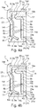
- the outer frame 9 has a substantially radial central portion 9b connected, on the one hand, to the inner portion 9a for fixing to the member 2 and, on the other hand, to a substantially axial outer portion 9c, the central portion 9b axially delimiting the annular chamber 10 with the inner portion 8b of the inner frame 8.
- the internal frame 8 carries a sealing element 14 which is disposed in the annular chamber 10, said element having at least one lip 14a, 14b, 14c which is disposed in rubbing contact on the outer frame 9.
- the sealing element 14 has a bead 14d which is placed in abutment on the outer member 1 to form a static seal.
- the outer portion 8a has a free edge 16 which is radially offset, in order to allow contact between the bead 14d and the outer axial wall 1b which guarantees the static seal.
- the sealing element 14 can be associated by overmolding with the internal frame 8.
- the sealing element 14 can be made of a flexible material, for example an elastomer, in particular based on butadiene nitrile copolymer (NBR ), optionally mechanically reinforced with fillers such as carbon black, hydrogenated NBR (HNBR), fluoropolymer or polyacrylate.
- NBR butadiene nitrile copolymer
- HNBR hydrogenated NBR
- the outer portion 9c of the outer frame 9 has a free end 17 which internally delimits the outer opening 12, said free end being inscribed in a radial plane P1 which is offset on the outer side with respect to a radial plane P2 in which is inscribed an outer face 15b of the central portion 9b.
- the outer face 15b of the central portion 9b extends radially.
- a housing for receiving an encoder 18 is formed on the outer face 15b, which makes it possible to equip the sealing device 7 with such an encoder without impacting the axial size of said device.
- the radial length of the external face 15b and the value of the offset between the radial planes P1, P2 define the volume available for the encoder 18.
- the sealing device 7 is equipped with an encoder 18 which is associated on the outer face 15b of the central portion 9b, said encoder having an axial thickness which is less than or equal to the offset between the radial planes P1, P2 in which respectively said outer face and the free end 17.
- the encoder 18 shown in the figures has a thickness which is substantially equal to the offset of the radial planes P1, P2, which makes it possible, in the axial bulk defined by the plane P1, to maximize the power of the signal emitted by said encoder.
- the sealing device 7 has sealing performance which is independent of the presence or absence of an encoder 18.
- the outer portion 9c of the outer frame 9 is devoid of an encoder.
- the rolling bearing comprises two sealing devices respectively left 7g and right 7d, the outer face 15b of the central portion 9b of the outer frame 9 on the right being equipped with an encoder 18, the outer face 15b of the portion central 9b of the outer frame 9 on the left being devoid of encoder.
- the encoder 18 may be formed of an annular magnet, in particular formed of an annular matrix, for example made from a plastic or elastomer material, in which magnetic particles are dispersed, by example of ferrite or rare earth particles such as NdFeB.
- the matrix can be overmolded on the external face 15b of the central portion 9b, which makes it possible to facilitate its association with the external frame 9, and therefore with the sealing device 7.
- the outer opening 12 is formed between the respective outer portions 8a, 9c of the inner 8 and outer 9 frames, the outer portion 8a of the inner frame 8 outwardly delimiting said outer opening.
- the outer portions 8a, 9c each have an axial wall, respectively outer 19a (for the outer frame 9) and inner 19b (for the inner frame 8), the axial walls 19a, 19b being arranged radially facing in forming a reduced clearance A defining an annular duct 20 extending over an axial length B and through which the annular chamber 10 opens into the external opening 12.
- the axial walls 19a, 19b both have sufficiently large dimensions to give the axial length B a maximum dimension, in order to improve the tightness of the device 7 at the level of the external opening 12.
- the parameters A and B are independent of the presence or absence of encoder 18, said parameters defining the geometry and therefore the performance of the entry baffle into chamber 10.
- the proposed arrangement makes it possible to obtain an annular duct 20 whose axial length B is large, in particular by being greater than the sum of the axial offset between the planes P1 and P2 and the thickness of the central portion 9b of the external frame 9, which makes it possible to combine an improvement in the tightness with an invariability of the lip 14a with or without encoder 18.
- the sealing element 14 is equipped with an outer web 14e which is associated on the inner axial wall 19b , in particular by being formed integrally with the bead 14d of static sealing.
- the sealing element 14 further comprises an inner web 14f which extends over the inner portion 8b of the inner frame 8, being formed in one piece with, on the one hand, the outer web 14e delimiting the outer duct 20 and, on the other hand, with the dynamic sealing lips 14a, 14b, 14c arranged in the annular chamber 10.
- the outer portion 9c has an outer segment 21 on which is formed the axial wall 19a delimiting the outer opening 12, said outer segment extending axially between an inner end 22 and the free end 17. Furthermore, the axial segment 21 is connected to the central portion 9b by a connecting segment 23.
- the connecting segment 23 has an inner segment which extends axially between an outer L-shaped end 24 for connecting with the central portion 9b and an inner end 22 in a U-shape connecting with the outer segment 21.
- outer 21 and inner 23 segments are joined radially, which makes it possible to limit the radial dimension of the outer frame 9, but also to increase the rigidity of said outer frame.
- the central portion 9b is directly connected to the fixing portion 9a on the inner member 2, in particular via an inner end 25 in L.
- the central portion 9b is connected to the fixing portion 9a by means of an inner portion 9d of the outer frame 9, said inner portion having an outer face 26 which is inscribed in a radial plane P3 which is offset from the outer side with respect to the radial plane P2 in which the outer face 15b of the central portion 9b is inscribed.
- a bearing zone is formed for the tool 28 for mounting the device 7 which is close to the inner member 2 while being offset from the outer face 15b for the association of an encoder. 18.
- the free end 17 and the outer face 26 are substantially inscribed in the same radial plane P1, P3, so that the tool 28 for mounting the sealing device 7 can simultaneously press on them during assembly of the bearing, as represented on the figures 6a and 6b .
- the encoder 18 has an axial thickness which is less than or equal to the offset between the radial planes P2, P3 between which the outer faces 15b, 26 of the respectively central portions 9b are inscribed. and interior 9d. Likewise, the inner portion 9d of the outer frame 9 has no encoder.
- the inner portion 9d has a segment 27 carrying the outer face 26, said segment having an L-shaped inner end 27a for connection with the fixing portion 9a.
- the segment 27 carrying the external face 26 extends radially.
- the inner portion 9d also has an outer segment 29 which extends axially between an L-shaped inner end 29a for connection with the central portion 9b and an L-shaped outer end 29b for connection with the segment 27 carrying the outer face 26.
- the outer segment 29 is joined radially around the fixing portion 9a, which makes it possible to increase the rigidity of the inner portion 9d, and thus to limit its deformation when the assembly tool 28 is pressed on it. .
- the internal 8 and external 9 frames are preassembled, forming between them the annular sealing chamber 10.
- a lubricant in the form of grease can be placed in the sealing chamber 10, in order to ensure both the lubrication of said chamber and to contribute to the cohesion of the reinforcements 8, 9 during their assembly.
- the method provides for placing a tool 28 resting on the inner portion 9d of the outer frame 9 and on the internal frame 8 to apply an axial displacement force of said reinforcements in said side over a course for fixing each of said reinforcements to a member 1, 2.
- the tool 28 has a bearing surface 30 which extends in a radial plane P, said bearing surface having a radial dimension which is greater than the radial dimension of the inner portion 9d.
- the bearing surface 30 is arranged to apply the displacement force jointly on the inner portion 9d and on the free end 17 of the outer frame 9, which makes it possible to facilitate the displacement of said external frame on its course for fixing to the member 2.
Landscapes
- Engineering & Computer Science (AREA)
- General Engineering & Computer Science (AREA)
- Mechanical Engineering (AREA)
- Rolling Contact Bearings (AREA)
Applications Claiming Priority (1)
| Application Number | Priority Date | Filing Date | Title |
|---|---|---|---|
| FR2001441A FR3107325B1 (fr) | 2020-02-13 | 2020-02-13 | Palier à roulement |
Publications (1)
| Publication Number | Publication Date |
|---|---|
| EP3865723A1 true EP3865723A1 (de) | 2021-08-18 |
Family
ID=70295422
Family Applications (1)
| Application Number | Title | Priority Date | Filing Date |
|---|---|---|---|
| EP21156100.6A Withdrawn EP3865723A1 (de) | 2020-02-13 | 2021-02-09 | Wälzlager |
Country Status (2)
| Country | Link |
|---|---|
| EP (1) | EP3865723A1 (de) |
| FR (1) | FR3107325B1 (de) |
Citations (6)
| Publication number | Priority date | Publication date | Assignee | Title |
|---|---|---|---|---|
| JP2004036817A (ja) * | 2002-07-05 | 2004-02-05 | Koyo Seiko Co Ltd | 転がり軸受の密封装置 |
| WO2006035616A1 (ja) * | 2004-09-29 | 2006-04-06 | Ntn Corporation | 磁気エンコーダおよびそれを備えた車輪用軸受装置 |
| JP2008083064A (ja) * | 2007-11-30 | 2008-04-10 | Ntn Corp | 車輪用軸受 |
| JP2009068687A (ja) * | 2007-08-21 | 2009-04-02 | Nok Corp | 金属嵌合部のシール構造およびこれに用いる金属部品 |
| US20090219017A1 (en) * | 2006-01-11 | 2009-09-03 | Uchiyama Manufacturing Corp | Tone Wheel and Method for Manufacturing The Same |
| JP2010091036A (ja) * | 2008-10-09 | 2010-04-22 | Jtekt Corp | 転がり軸受装置 |
-
2020
- 2020-02-13 FR FR2001441A patent/FR3107325B1/fr active Active
-
2021
- 2021-02-09 EP EP21156100.6A patent/EP3865723A1/de not_active Withdrawn
Patent Citations (6)
| Publication number | Priority date | Publication date | Assignee | Title |
|---|---|---|---|---|
| JP2004036817A (ja) * | 2002-07-05 | 2004-02-05 | Koyo Seiko Co Ltd | 転がり軸受の密封装置 |
| WO2006035616A1 (ja) * | 2004-09-29 | 2006-04-06 | Ntn Corporation | 磁気エンコーダおよびそれを備えた車輪用軸受装置 |
| US20090219017A1 (en) * | 2006-01-11 | 2009-09-03 | Uchiyama Manufacturing Corp | Tone Wheel and Method for Manufacturing The Same |
| JP2009068687A (ja) * | 2007-08-21 | 2009-04-02 | Nok Corp | 金属嵌合部のシール構造およびこれに用いる金属部品 |
| JP2008083064A (ja) * | 2007-11-30 | 2008-04-10 | Ntn Corp | 車輪用軸受 |
| JP2010091036A (ja) * | 2008-10-09 | 2010-04-22 | Jtekt Corp | 転がり軸受装置 |
Also Published As
| Publication number | Publication date |
|---|---|
| FR3107325B1 (fr) | 2023-05-19 |
| FR3107325A1 (fr) | 2021-08-20 |
Similar Documents
| Publication | Publication Date | Title |
|---|---|---|
| CN102481959B (zh) | 滚轮装置 | |
| EP3626486A1 (de) | Aufhängungsanschlag eines kraftfahrzeugs | |
| WO2012107693A1 (fr) | Palier a roulement presentant une extension annulaire et un dispositif d'etancheite | |
| EP1277978A1 (de) | Kegelrollenlager mit einer Dichtungsanordnung | |
| EP2526317B1 (de) | Kraftfahrzeug-kupplungsausrücklager mit einer abdichtvorrichtung | |
| FR3001509A1 (fr) | Palier a roulement notamment pour systeme d’entrainement en rotation d’une roue de vehicule automobile | |
| EP3865723A1 (de) | Wälzlager | |
| FR2874671A1 (fr) | Palier a roulement a passage d'air comprenant une chambre etanche avec deflecteur | |
| FR3001781A1 (fr) | Palier a roulement | |
| EP3784915B1 (de) | Wälzlager | |
| EP2821662B1 (de) | Radnaben-Wälzlageranordnung für ein Kraftfahrzeug mit einer Dichtungsvorrichtung | |
| EP3680500B1 (de) | Wälzlager, das mit einer abdichtvorrichtung ausgestattet ist | |
| FR3010753A1 (fr) | Dispositif de butee de debrayage, notamment pour embrayage de vehicule automobile | |
| EP3015728B1 (de) | Wälzlager, das mit einer abdichtvorrichtung einschliesslich einer armatur ausgestattet ist | |
| EP4311957A1 (de) | Statische dichtung und radnabenanordnung mit einer solchen dichtung | |
| WO2017055724A1 (fr) | Palier à roulement | |
| FR2675862A1 (fr) | Roulement a capteur tachymetrique. | |
| FR2888625A1 (fr) | Procede de montage d'un palier pourvu d'un flasque et a deux rangees de corps roulants | |
| FR3114850A1 (fr) | Dispositif d’étanchéité pour palier à roulement | |
| EP3299649B1 (de) | Wälzlager, das mit einer abdichtvorrichtung ausgestattet ist | |
| FR3120668A1 (fr) | Dispositif d’étanchéité pour palier comprenant un passage amont équipé d’une gouttière | |
| FR3018874A1 (fr) | Palier a roulement equipe d’un dispositif d’etancheite comprenant une armature | |
| FR3034708B1 (fr) | Systeme d'entrainement en rotation d'une roue de vehicule automobile | |
| FR3109416A1 (fr) | Dispositif d’étanchéité pour un palier à roulement | |
| FR2904671A1 (fr) | Systeme d'articulation instrumente. |
Legal Events
| Date | Code | Title | Description |
|---|---|---|---|
| PUAI | Public reference made under article 153(3) epc to a published international application that has entered the european phase |
Free format text: ORIGINAL CODE: 0009012 |
|
| STAA | Information on the status of an ep patent application or granted ep patent |
Free format text: STATUS: THE APPLICATION HAS BEEN PUBLISHED |
|
| AK | Designated contracting states |
Kind code of ref document: A1 Designated state(s): AL AT BE BG CH CY CZ DE DK EE ES FI FR GB GR HR HU IE IS IT LI LT LU LV MC MK MT NL NO PL PT RO RS SE SI SK SM TR |
|
| STAA | Information on the status of an ep patent application or granted ep patent |
Free format text: STATUS: THE APPLICATION IS DEEMED TO BE WITHDRAWN |
|
| 18D | Application deemed to be withdrawn |
Effective date: 20220219 |