EP3865736A1 - Roue de frein de stationnement, frein de stationnement et procédé de fabrication d'une roue de frein de stationnement - Google Patents
Roue de frein de stationnement, frein de stationnement et procédé de fabrication d'une roue de frein de stationnement Download PDFInfo
- Publication number
- EP3865736A1 EP3865736A1 EP21151481.5A EP21151481A EP3865736A1 EP 3865736 A1 EP3865736 A1 EP 3865736A1 EP 21151481 A EP21151481 A EP 21151481A EP 3865736 A1 EP3865736 A1 EP 3865736A1
- Authority
- EP
- European Patent Office
- Prior art keywords
- component
- parking lock
- connecting device
- lock gear
- grooves
- Prior art date
- Legal status (The legal status is an assumption and is not a legal conclusion. Google has not performed a legal analysis and makes no representation as to the accuracy of the status listed.)
- Withdrawn
Links
- 238000004519 manufacturing process Methods 0.000 title claims description 8
- 238000000034 method Methods 0.000 title description 7
- 230000005540 biological transmission Effects 0.000 claims abstract description 15
- 239000013013 elastic material Substances 0.000 claims abstract description 13
- 229920001971 elastomer Polymers 0.000 claims description 12
- 239000002184 metal Substances 0.000 claims description 9
- 229910052751 metal Inorganic materials 0.000 claims description 9
- 230000001681 protective effect Effects 0.000 claims description 5
- 239000000806 elastomer Substances 0.000 claims description 3
- 239000005060 rubber Substances 0.000 description 9
- 238000013016 damping Methods 0.000 description 4
- 230000001413 cellular effect Effects 0.000 description 2
- 230000005283 ground state Effects 0.000 description 2
- 229920002521 macromolecule Polymers 0.000 description 2
- 229920000642 polymer Polymers 0.000 description 2
- 244000043261 Hevea brasiliensis Species 0.000 description 1
- 230000007423 decrease Effects 0.000 description 1
- 230000001627 detrimental effect Effects 0.000 description 1
- 230000005489 elastic deformation Effects 0.000 description 1
- 230000002349 favourable effect Effects 0.000 description 1
- 229920001821 foam rubber Polymers 0.000 description 1
- 230000001771 impaired effect Effects 0.000 description 1
- 239000000463 material Substances 0.000 description 1
- 150000002739 metals Chemical class 0.000 description 1
- 229920003052 natural elastomer Polymers 0.000 description 1
- 229920001194 natural rubber Polymers 0.000 description 1
- 239000011148 porous material Substances 0.000 description 1
- 238000005096 rolling process Methods 0.000 description 1
- 239000000126 substance Substances 0.000 description 1
- 229920003051 synthetic elastomer Polymers 0.000 description 1
- 239000005061 synthetic rubber Substances 0.000 description 1
- 238000003466 welding Methods 0.000 description 1
Images


Classifications
-
- F—MECHANICAL ENGINEERING; LIGHTING; HEATING; WEAPONS; BLASTING
- F16—ENGINEERING ELEMENTS AND UNITS; GENERAL MEASURES FOR PRODUCING AND MAINTAINING EFFECTIVE FUNCTIONING OF MACHINES OR INSTALLATIONS; THERMAL INSULATION IN GENERAL
- F16H—GEARING
- F16H63/00—Control outputs from the control unit to change-speed- or reversing-gearings for conveying rotary motion or to other devices than the final output mechanism
- F16H63/02—Final output mechanisms therefor; Actuating means for the final output mechanisms
- F16H63/30—Constructional features of the final output mechanisms
- F16H63/34—Locking or disabling mechanisms
- F16H63/3416—Parking lock mechanisms or brakes in the transmission
- F16H63/3425—Parking lock mechanisms or brakes in the transmission characterised by pawls or wheels
Definitions
- the present invention relates to a parking lock gear.
- the invention also relates to a parking lock.
- the invention relates to a method for producing a parking lock gear.
- a vehicle When stationary, a vehicle should be secured against rolling away. In particular, the vehicle must not move even on steep slopes. In vehicles with a manual gearbox, a gear can be engaged for this purpose, whereby the resulting power flow to the drive wheels prevents the vehicle from driving away. However, this is not possible for automatic transmissions. Parking locks are therefore typically used, which mechanically prevent the vehicle from driving away.
- the parking lock can be activated by the driver by moving the selector lever into the appropriate position.
- a pawl When the parking lock is activated, a pawl is moved mechanically or hydraulically into a locking position. The pawl engages in grooves of a parking lock gear, the parking lock gear being arranged on the transmission shaft.
- a return spring brings the pawl back to its original state so that it no longer engages in the grooves of the parking lock wheel.
- Both the pawl and the parking lock gear are typically made of metal and therefore have a very high level of rigidity. This creates a very high torque in the entire transmission. This can have detrimental effects on transmission elements. For example, splines, running gears, Bearings and other elements moving in the flow of forces are impaired, damaged or even destroyed.
- the invention provides a parking lock gear with the features of claim 1, a parking lock with the features of claim 9 and a method for producing a parking lock gear with the features of claim 10.
- the invention accordingly relates to a parking lock gear with an inner first component, wherein the first component is configured in an annular manner, and wherein the first component can be or is arranged on a transmission shaft.
- the parking lock gear further comprises an outer second component, wherein the second component is configured annularly, and wherein the second component has a plurality of grooves on a radially outer side of the parking lock gear, the grooves being designed such that a pawl engages the grooves can be brought.
- the parking lock gear finally comprises a connecting device which is formed from an elastic material, the first component being coupled to the second component by means of the connecting device.
- the invention relates to a parking lock with a parking lock gear according to the invention and a pawl which is designed to be brought into engagement with the grooves of the parking lock gear.
- the invention relates to a method for producing a parking lock gear.
- An inner first component is provided, wherein the first component is configured in an annular manner, and wherein the first component is arranged on a transmission shaft.
- a connecting device is attached to the first component, the connecting device being at least partially formed from an elastic material.
- An outer second component is attached to the connecting device, so that the first component is coupled to the second component by means of the connecting device, wherein the second component is configured in an annular manner, and wherein the second component has a plurality of grooves on a radially outer side of the parking lock gear, wherein the grooves are formed such that a pawl can be brought into engagement with the grooves.
- the parking lock gear according to the invention has a connecting device made of an elastic material, which connects inner and outer components to one another.
- the connecting device made of the elastic material serves as a damper and thereby dampens the high torques that occur.
- the damper is first elastically deformed in the direction of rotation, i.e. perpendicular to the radial direction, before the torque is transmitted to the inner component.
- the connecting device designed as a damper is fully integrated into the parking lock gear itself. As a result, no additional mechanical components are required, which can be prone to wear.
- the parking lock gear according to the invention is thus distinguished by good damping properties and high durability.
- the connecting device is configured in a ring shape.
- the connecting device can, for example, the Have the shape of a rubber ring.
- the connecting device has a plurality of connecting elements which are arranged at a distance from one another and which connect the first component to the second component.
- a cavity can be formed between the connecting elements of the connecting device.
- the connecting device is at least partially made of elastomers.
- the connecting device can be formed at least partially from an entropy-elastic or rubber-elastic material.
- Polymers comprise macromolecules or molecule segments which are in a coiled state in the ground state. When stressed, the macromolecules or molecule segments are stretched.
- Entropy elasticity or rubber elasticity describes the property characteristic of polymers of returning to the entropically more favorable ground state after stretching. When stretched, the entropy of rubber-elastic materials decreases. In contrast, hard materials, such as metals, have an increased internal energy.
- the connecting device is at least partially made of natural rubber or synthetic rubber.
- the connecting device can also at least partially consist of pore rubber, cellular rubber, cellular rubber, sponge rubber, foam rubber or the like.
- the first component and the second component are at least partially made of metal.
- both the first component and the second component are made entirely of metal.
- the first component and / or the second component comprise several segments.
- the first component and / or the second component can consist of semicircular segments which are connected to one another when the parking lock gear is mounted on the transmission shaft.
- the parking lock gear has a protective cover which at least partially surrounds the first component, the second component and the connecting device.
- the protective cover can protect the elastic connecting device from external chemical or physical influences and thereby ensure the improvement of the deformation properties over a long period of time.
- the protective cover can be made at least partially from metal.
- the first component has no direct connection to the second component.
- the first component is preferably only connected to the second component via the connecting device.
- the two components can touch each other at certain points under high load. These mechanical stop surfaces are required to protect the rubber element in cases of abuse.
- the first component and / or the second component have a groove for receiving the connecting device.
- the connecting device can be designed in the shape of a ring and fully engage in the groove. This prevents the connecting device from slipping.
- the pawl is made of metal.
- Figure 1 shows a schematic cross-sectional view of a parking lock 1 in the parked state of the vehicle.
- the parking lock 1 comprises a pawl 2 and a parking lock wheel 3a.
- the parking lock gear 3a has a first component 31, a second component 32a and a connecting device or a connecting element 33.
- the connecting device 33 is a damping element and can be at least partially formed from an elastomer, in particular rubber.
- the first component 31 and the second component 32a are each made of metal.
- the first component 31 and second component 32a are in Essentially ring-shaped, the second component 32a having a plurality of grooves 32a-i.
- the invention is not limited to a specific number of grooves 32a-i.
- the second component 32a can have a greater or lesser number of grooves 32a-i than in FIG Figure 1 illustrated.
- the connecting device 33 is also annular and connects the first component 31 to the second component 32a.
- the connecting device 33 consists at least partially of an elastic material.
- the connecting device 33 is preferably made entirely of an elastic material.
- the position shown of the parking lock 1 engages the pawl 2 in a groove 32a-i of the parking lock gear 3a.
- the pawl 2 is brought into the engagement position by a mechanism (not shown) of the parking lock 1.
- mechanical or hydraulic actuators are activated by a driver of the vehicle by selecting a parking position on the selector lever, which act against a bias and exert a force on the pawl 2 and thereby move it in the direction of the parking lock wheel 3a.
- a nose of the pawl 2 is thereby brought into engagement with one of the grooves 32a-i.
- the first component 31 is arranged on a transmission shaft of the vehicle and connected to the transmission shaft in a rotationally fixed manner. Since the pawl 2 engages in one of the grooves 32a-i, rotation of the gear shaft is prevented.
- FIG. 11 shows a schematic cross-sectional view of the FIG Figure 1 Parking lock 1 shown in the driving state of the vehicle. If the driver of the vehicle again selects another mode than the parking mode by means of a corresponding selection, the actuators are activated in such a way that the pawl 2 is brought into the starting position due to the bias and thus no longer engages in one of the grooves 32a-i. A rotation of the parking lock gear 3a and thereby the transmission shaft on which the parking lock gear 3a is arranged is no longer prevented by the pawl 2.
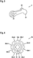
- Figure 3 shows a schematic oblique view of a pawl 2 of a parking lock 1.
- the pawl 2 comprises a hole 23 for attachment to a pin about which the pawl 2 can rotate.
- the pawl 2 further comprises a first lug 22, which can be moved by an actuator against a bias in the direction of the grooves 32a-i of the parking lock gear 3a.
- the pawl 2 further comprises a second nose 21, which can engage in the grooves 32a-i of the parking lock gear 3a.
- FIG 4 shows a schematic cross-sectional view of a further parking lock gear 3b.
- the parking lock gear 3b comprises a first component 31 and a second component 32b, which are connected via a connecting device 33.
- the first component 31 can be arranged positively and / or non-positively on a transmission shaft.
- the second component 32b includes a plurality of grooves 32b-1 to 32b-8, and a pawl 2 is engageable with the grooves 32b-1 to 32b-8. While eight grooves 32b-1 to 32b-8 are provided in the embodiment shown, the invention is not limited to such an embodiment.
- the connecting device 33 is formed from an elastic material.
- Figure 5 shows a flow chart of a method for producing a parking lock gear 3a, 3b.
- an inner first component 31 is produced, which is configured in the shape of a ring.
- the first component is arranged on a gear shaft.
- a connecting device 33 which serves as a damping element, is arranged on the first component 31.
- the connecting device 33 is made of an elastic material such as rubber.
- the connecting device 33 is preferably also designed in the shape of a ring.
- the connecting device 33 can have a plurality of connecting elements which are arranged at a distance from one another and which connect the first component 31 to the second component 32a, 32b.
- an outer second component 32a, 32b is arranged on the connecting device 33.
- This is also designed in a ring shape and has a plurality of grooves 32a-i, 32b-i on the radially outer side, so that in the assembled state a pawl 2 can be brought into engagement with the grooves 32a-i, 32b-i.
- the second component 32a, 32b is preferably only indirectly connected to the first component 31 via the connecting device 33, but has no direct contact point.
- the first component 31 and the second component 32a, 32b can each be formed from metal. Furthermore, when producing the parking lock gear 3a, 3b, a protective cover can be attached which at least partially surrounds the first component 31, the second component 32a, 32b and the connecting device 33.
- a groove is provided in the first component 31 and / or in the second component 32a, 32b, the connecting device 33 being fitted into the groove.
- the method steps S1 to S3 do not have to be carried out in the order mentioned.
- the parking lock gear 3a, 3b can also be fully assembled first before it is attached to the transmission shaft.
- first component 31 and / or the second component 32 consist of elements which are connected to one another during the manufacture of the parking lock gear.
- the components can be connected to one another by fitting, screwing or welding.
Landscapes
- Engineering & Computer Science (AREA)
- General Engineering & Computer Science (AREA)
- Mechanical Engineering (AREA)
- Gear-Shifting Mechanisms (AREA)
Applications Claiming Priority (1)
| Application Number | Priority Date | Filing Date | Title |
|---|---|---|---|
| DE102020201729.8A DE102020201729A1 (de) | 2020-02-12 | 2020-02-12 | Parksperrenrad, Parksperre und Verfahren zum Herstellen eines Parksperrenrades |
Publications (1)
| Publication Number | Publication Date |
|---|---|
| EP3865736A1 true EP3865736A1 (fr) | 2021-08-18 |
Family
ID=74183072
Family Applications (1)
| Application Number | Title | Priority Date | Filing Date |
|---|---|---|---|
| EP21151481.5A Withdrawn EP3865736A1 (fr) | 2020-02-12 | 2021-01-14 | Roue de frein de stationnement, frein de stationnement et procédé de fabrication d'une roue de frein de stationnement |
Country Status (2)
| Country | Link |
|---|---|
| EP (1) | EP3865736A1 (fr) |
| DE (1) | DE102020201729A1 (fr) |
Cited By (1)
| Publication number | Priority date | Publication date | Assignee | Title |
|---|---|---|---|---|
| FR3126950A1 (fr) * | 2021-09-10 | 2023-03-17 | Punch Powerglide Strasbourg | Dispositif de stationnement pour véhicule automobile électrique |
Families Citing this family (1)
| Publication number | Priority date | Publication date | Assignee | Title |
|---|---|---|---|---|
| DE102021200579B3 (de) | 2021-01-22 | 2022-04-28 | Magna powertrain gmbh & co kg | Parksperrenanordnung mit einem Ausgleichselement |
Citations (7)
| Publication number | Priority date | Publication date | Assignee | Title |
|---|---|---|---|---|
| DE19535239C1 (de) | 1995-09-22 | 1996-12-12 | Daimler Benz Ag | Parksperre für Fahrzeuge |
| US6419068B1 (en) * | 2000-10-24 | 2002-07-16 | Ford Global Technologies, Inc. | Park gear damper for an automatic transmission for an automotive vehicle |
| JP2007321862A (ja) * | 2006-05-31 | 2007-12-13 | Hitachi Ltd | 電動ディスクブレーキ |
| US20090053486A1 (en) * | 2006-03-23 | 2009-02-26 | The Timken Company | Wear and corrosion resistant coating |
| DE102013204174A1 (de) * | 2013-03-12 | 2014-09-18 | Bayerische Motoren Werke Aktiengesellschaft | Fahrzeug mit einer Parksperrenanordnung |
| DE102015013285A1 (de) * | 2015-10-13 | 2016-05-25 | Daimler Ag | Verfahren zum Einlegen einer Parksperre eines Getriebes |
| CN106838305A (zh) * | 2017-03-20 | 2017-06-13 | 河北工业大学 | 一种自动变速器的驻车机构 |
-
2020
- 2020-02-12 DE DE102020201729.8A patent/DE102020201729A1/de active Pending
-
2021
- 2021-01-14 EP EP21151481.5A patent/EP3865736A1/fr not_active Withdrawn
Patent Citations (7)
| Publication number | Priority date | Publication date | Assignee | Title |
|---|---|---|---|---|
| DE19535239C1 (de) | 1995-09-22 | 1996-12-12 | Daimler Benz Ag | Parksperre für Fahrzeuge |
| US6419068B1 (en) * | 2000-10-24 | 2002-07-16 | Ford Global Technologies, Inc. | Park gear damper for an automatic transmission for an automotive vehicle |
| US20090053486A1 (en) * | 2006-03-23 | 2009-02-26 | The Timken Company | Wear and corrosion resistant coating |
| JP2007321862A (ja) * | 2006-05-31 | 2007-12-13 | Hitachi Ltd | 電動ディスクブレーキ |
| DE102013204174A1 (de) * | 2013-03-12 | 2014-09-18 | Bayerische Motoren Werke Aktiengesellschaft | Fahrzeug mit einer Parksperrenanordnung |
| DE102015013285A1 (de) * | 2015-10-13 | 2016-05-25 | Daimler Ag | Verfahren zum Einlegen einer Parksperre eines Getriebes |
| CN106838305A (zh) * | 2017-03-20 | 2017-06-13 | 河北工业大学 | 一种自动变速器的驻车机构 |
Cited By (1)
| Publication number | Priority date | Publication date | Assignee | Title |
|---|---|---|---|---|
| FR3126950A1 (fr) * | 2021-09-10 | 2023-03-17 | Punch Powerglide Strasbourg | Dispositif de stationnement pour véhicule automobile électrique |
Also Published As
| Publication number | Publication date |
|---|---|
| DE102020201729A1 (de) | 2021-08-12 |
Similar Documents
| Publication | Publication Date | Title |
|---|---|---|
| EP2479459B1 (fr) | Dispositif de stockage d'un arbre de pignon d'un différentiel pour véhicule automobile | |
| WO2008122277A2 (fr) | Ensemble roulement de roue | |
| DE102019205602A1 (de) | Parksperrenrad und Parksperrenanordnung | |
| DE102020117721B3 (de) | Radlagereinheit für ein Kraftfahrzeug | |
| WO2015058754A1 (fr) | Différentiel léger pourvu d'une denture de frein de stationnement | |
| DE102006049229A1 (de) | Elektrischer Parkbrems-Aktuator mit Planetengetriebe | |
| DE102021114251A1 (de) | Parksperre für ein Fahrzeug | |
| EP4276332A1 (fr) | Engrenage à onde de déformation | |
| EP3882478B1 (fr) | Chaine cinématique avec un accouplement extensible entre un arbre moteur et un arbre d'entrée d'une boîte de vitesses | |
| EP3865736A1 (fr) | Roue de frein de stationnement, frein de stationnement et procédé de fabrication d'une roue de frein de stationnement | |
| DE19754260A1 (de) | Sicherheitseinrichtung für ein Getriebe | |
| WO2006097194A1 (fr) | Procede pour produire une liaison articulee et liaison articulee | |
| EP1294594B1 (fr) | Limiteur de charge et son procede de production | |
| DE102015009051A1 (de) | Zahnrad, insbesondere für einen Kraftwagen, sowie Verfahren zum Herstellen eines Zahnrads | |
| EP3339682A1 (fr) | Pignon baladeur pour un dispositif de boîte à pignons baladeurs | |
| WO2009109255A2 (fr) | Unité de précontrainte | |
| WO2020182399A1 (fr) | Différentiel | |
| EP2406515B1 (fr) | Unite de precontrainte axiale a reglage | |
| DE102006012031A1 (de) | Verfahren zur Herstellung einer Gelenkanbindung und Gelenkanbindung | |
| WO2021004578A1 (fr) | Dispositif de verrouillage de stationnement pour un essieu moteur électrique et essieu moteur électrique comprenant un dispositif de verrouillage de stationnement | |
| DE102019134517A1 (de) | Sperrklinke für eine Parksperre | |
| EP3405692B1 (fr) | Arbre de transmission, appariement de pièces et procédé pour faire fonctionner un arbre de transmission | |
| DE102019127865A1 (de) | Planetenwälzgetriebe und Verfahren zur Herstellung eines Planetenwälzgetriebes | |
| DE102022111705A1 (de) | Spannungswellengetriebe | |
| DE102018124444A1 (de) | Rampenaktuator und Schrägkugellagereinheit mit kaltumgeformtem Außenring und geprägter Rampenkontur sowie Verfahren zum Herstellen einer Rampenscheibe |
Legal Events
| Date | Code | Title | Description |
|---|---|---|---|
| PUAI | Public reference made under article 153(3) epc to a published international application that has entered the european phase |
Free format text: ORIGINAL CODE: 0009012 |
|
| STAA | Information on the status of an ep patent application or granted ep patent |
Free format text: STATUS: THE APPLICATION HAS BEEN PUBLISHED |
|
| AK | Designated contracting states |
Kind code of ref document: A1 Designated state(s): AL AT BE BG CH CY CZ DE DK EE ES FI FR GB GR HR HU IE IS IT LI LT LU LV MC MK MT NL NO PL PT RO RS SE SI SK SM TR |
|
| STAA | Information on the status of an ep patent application or granted ep patent |
Free format text: STATUS: REQUEST FOR EXAMINATION WAS MADE |
|
| 17P | Request for examination filed |
Effective date: 20220218 |
|
| RBV | Designated contracting states (corrected) |
Designated state(s): AL AT BE BG CH CY CZ DE DK EE ES FI FR GB GR HR HU IE IS IT LI LT LU LV MC MK MT NL NO PL PT RO RS SE SI SK SM TR |
|
| STAA | Information on the status of an ep patent application or granted ep patent |
Free format text: STATUS: EXAMINATION IS IN PROGRESS |
|
| 17Q | First examination report despatched |
Effective date: 20220810 |
|
| STAA | Information on the status of an ep patent application or granted ep patent |
Free format text: STATUS: THE APPLICATION IS DEEMED TO BE WITHDRAWN |
|
| 18D | Application deemed to be withdrawn |
Effective date: 20241106 |