EP3868016B1 - Fonctionnement des éléments de commutation d'un convertisseur d'énergie multiniveau - Google Patents
Fonctionnement des éléments de commutation d'un convertisseur d'énergie multiniveau Download PDFInfo
- Publication number
- EP3868016B1 EP3868016B1 EP19829092.6A EP19829092A EP3868016B1 EP 3868016 B1 EP3868016 B1 EP 3868016B1 EP 19829092 A EP19829092 A EP 19829092A EP 3868016 B1 EP3868016 B1 EP 3868016B1
- Authority
- EP
- European Patent Office
- Prior art keywords
- switching elements
- voltage
- phase
- voltage signal
- switching
- Prior art date
- Legal status (The legal status is an assumption and is not a legal conclusion. Google has not performed a legal analysis and makes no representation as to the accuracy of the status listed.)
- Active
Links
Images




Classifications
-
- H—ELECTRICITY
- H02—GENERATION; CONVERSION OR DISTRIBUTION OF ELECTRIC POWER
- H02P—CONTROL OR REGULATION OF ELECTRIC MOTORS, ELECTRIC GENERATORS OR DYNAMO-ELECTRIC CONVERTERS; CONTROLLING TRANSFORMERS, REACTORS OR CHOKE COILS
- H02P1/00—Arrangements for starting electric motors or dynamo-electric converters
- H02P1/16—Arrangements for starting electric motors or dynamo-electric converters for starting dynamo-electric motors or dynamo-electric converters
-
- H—ELECTRICITY
- H02—GENERATION; CONVERSION OR DISTRIBUTION OF ELECTRIC POWER
- H02M—APPARATUS FOR CONVERSION BETWEEN AC AND AC, BETWEEN AC AND DC, OR BETWEEN DC AND DC, AND FOR USE WITH MAINS OR SIMILAR POWER SUPPLY SYSTEMS; CONVERSION OF DC OR AC INPUT POWER INTO SURGE OUTPUT POWER; CONTROL OR REGULATION THEREOF
- H02M1/00—Details of apparatus for conversion
- H02M1/32—Means for protecting converters other than automatic disconnection
- H02M1/327—Means for protecting converters other than automatic disconnection against abnormal temperatures
-
- H—ELECTRICITY
- H02—GENERATION; CONVERSION OR DISTRIBUTION OF ELECTRIC POWER
- H02M—APPARATUS FOR CONVERSION BETWEEN AC AND AC, BETWEEN AC AND DC, OR BETWEEN DC AND DC, AND FOR USE WITH MAINS OR SIMILAR POWER SUPPLY SYSTEMS; CONVERSION OF DC OR AC INPUT POWER INTO SURGE OUTPUT POWER; CONTROL OR REGULATION THEREOF
- H02M7/00—Conversion of AC power input into DC power output; Conversion of DC power input into AC power output
- H02M7/42—Conversion of DC power input into AC power output without possibility of reversal
- H02M7/44—Conversion of DC power input into AC power output without possibility of reversal by static converters
- H02M7/48—Conversion of DC power input into AC power output without possibility of reversal by static converters using discharge tubes with control electrode or semiconductor devices with control electrode
- H02M7/483—Converters with outputs that each can have more than two voltages levels
-
- H—ELECTRICITY
- H02—GENERATION; CONVERSION OR DISTRIBUTION OF ELECTRIC POWER
- H02M—APPARATUS FOR CONVERSION BETWEEN AC AND AC, BETWEEN AC AND DC, OR BETWEEN DC AND DC, AND FOR USE WITH MAINS OR SIMILAR POWER SUPPLY SYSTEMS; CONVERSION OF DC OR AC INPUT POWER INTO SURGE OUTPUT POWER; CONTROL OR REGULATION THEREOF
- H02M7/00—Conversion of AC power input into DC power output; Conversion of DC power input into AC power output
- H02M7/42—Conversion of DC power input into AC power output without possibility of reversal
- H02M7/44—Conversion of DC power input into AC power output without possibility of reversal by static converters
- H02M7/48—Conversion of DC power input into AC power output without possibility of reversal by static converters using discharge tubes with control electrode or semiconductor devices with control electrode
- H02M7/53—Conversion of DC power input into AC power output without possibility of reversal by static converters using discharge tubes with control electrode or semiconductor devices with control electrode using devices of a triode or transistor type requiring continuous application of a control signal
- H02M7/537—Conversion of DC power input into AC power output without possibility of reversal by static converters using discharge tubes with control electrode or semiconductor devices with control electrode using devices of a triode or transistor type requiring continuous application of a control signal using semiconductor devices only, e.g. single switched pulse inverters
-
- H—ELECTRICITY
- H02—GENERATION; CONVERSION OR DISTRIBUTION OF ELECTRIC POWER
- H02M—APPARATUS FOR CONVERSION BETWEEN AC AND AC, BETWEEN AC AND DC, OR BETWEEN DC AND DC, AND FOR USE WITH MAINS OR SIMILAR POWER SUPPLY SYSTEMS; CONVERSION OF DC OR AC INPUT POWER INTO SURGE OUTPUT POWER; CONTROL OR REGULATION THEREOF
- H02M7/00—Conversion of AC power input into DC power output; Conversion of DC power input into AC power output
- H02M7/42—Conversion of DC power input into AC power output without possibility of reversal
- H02M7/44—Conversion of DC power input into AC power output without possibility of reversal by static converters
- H02M7/48—Conversion of DC power input into AC power output without possibility of reversal by static converters using discharge tubes with control electrode or semiconductor devices with control electrode
- H02M7/53—Conversion of DC power input into AC power output without possibility of reversal by static converters using discharge tubes with control electrode or semiconductor devices with control electrode using devices of a triode or transistor type requiring continuous application of a control signal
- H02M7/537—Conversion of DC power input into AC power output without possibility of reversal by static converters using discharge tubes with control electrode or semiconductor devices with control electrode using devices of a triode or transistor type requiring continuous application of a control signal using semiconductor devices only, e.g. single switched pulse inverters
- H02M7/539—Conversion of DC power input into AC power output without possibility of reversal by static converters using discharge tubes with control electrode or semiconductor devices with control electrode using devices of a triode or transistor type requiring continuous application of a control signal using semiconductor devices only, e.g. single switched pulse inverters with automatic control of output wave form or frequency
-
- H—ELECTRICITY
- H02—GENERATION; CONVERSION OR DISTRIBUTION OF ELECTRIC POWER
- H02P—CONTROL OR REGULATION OF ELECTRIC MOTORS, ELECTRIC GENERATORS OR DYNAMO-ELECTRIC CONVERTERS; CONTROLLING TRANSFORMERS, REACTORS OR CHOKE COILS
- H02P27/00—Arrangements or methods for the control of AC motors characterised by the kind of supply voltage
- H02P27/04—Arrangements or methods for the control of AC motors characterised by the kind of supply voltage using variable-frequency supply voltage, e.g. inverter or converter supply voltage
- H02P27/06—Arrangements or methods for the control of AC motors characterised by the kind of supply voltage using variable-frequency supply voltage, e.g. inverter or converter supply voltage using DC to AC converters or inverters
- H02P27/08—Arrangements or methods for the control of AC motors characterised by the kind of supply voltage using variable-frequency supply voltage, e.g. inverter or converter supply voltage using DC to AC converters or inverters with pulse width modulation
- H02P27/14—Arrangements or methods for the control of AC motors characterised by the kind of supply voltage using variable-frequency supply voltage, e.g. inverter or converter supply voltage using DC to AC converters or inverters with pulse width modulation with three or more levels of voltage
Definitions
- the invention relates to a method for operating switching elements of a multi-level energy converter that uses at least three electrical potentials and to which a multi-phase electrical machine is connected, wherein switching elements of the multi-level energy converter are operated by means of corresponding switching signals in a predetermined clock operation, wherein the switching signals for the switching elements assigned to a respective one of the phases are determined as a function of a respective target voltage signal in order to apply a respective phase voltage to each phase of the multi-phase electrical machine.
- the invention relates to a control unit for controlling switching elements of a multi-level energy converter that uses at least three electrical potentials and is designed to be connected to a multi-phase electrical machine, wherein the control unit is designed to operate the switching elements of the multi-level energy converter by means of corresponding switching signals in a predetermined clock operation, for which purpose the control unit determines the switching signals for the switching elements assigned to a respective one of the phases as a function of a respective target voltage signal in order to apply a respective phase voltage to each phase of the multi-phase electrical machine.
- the invention further relates to a multi-level energy converter which is designed to be connected to a multi-phase electrical machine and which uses at least three electrical potentials, with switching elements for applying a respective phase voltage to each phase of the multi-phase electrical machine, and a control unit for controlling the switching elements in a predetermined clock operation by means of corresponding switching signals.
- the invention also relates to a drive device with a multi-phase electrical machine and a multi-level energy converter connected to the multi-phase electrical machine, which uses at least three electrical potentials.
- Multi-level energy converters are specific energy converters that use several electrical potentials for the purpose of carrying out the energy conversion function, which can be provided, for example, by one or more DC voltage intermediate circuits.
- the invention is directed in particular at such multi-level energy converters that use at least three electrical potentials to implement the desired energy conversion function.
- Such multi-level energy converters are often used in the field of energy supply or power drives.
- such multi-level energy converters are operated bidirectionally, so that electrical energy can be converted from the AC side to the DC side and vice versa.
- a multi-level energy converter is known, for example, from the WO 02/23703 A1 .
- the EP 2 849 331 A1 aims to balance the voltage across a capacitive voltage divider of a multi-level energy converter. This compensates for a voltage difference at the neutral point.
- the WO2019137916 A1 discloses a method for controlling an electrical converter, wherein the electrical converter is designed to convert a direct current voltage into a multiphase voltage having at least two voltage levels.
- Multi-level energy converters are generally used to couple one or more DC intermediate circuits to an AC network, in particular a multi-phase AC network.
- the AC network is often provided by a corresponding multi-phase electrical machine.
- the multi-level energy converter is adapted to the multi-phase electrical machine in this respect, so that each of the phases of the electrical machine can be supplied with electrical energy accordingly.
- Multiphase electrical machines are also widely known in the prior art. These are used in the prior art for a variety of applications in which specific drive functions are to be implemented using the multiphase electrical machine.
- the use of three-phase electrical machines is particularly widespread, which - depending on the application - can even be coupled directly to a three-phase public power supply network in order to provide the desired drive function.
- the control options in such a scenario are limited, which is why the multiphase electrical machines are now usually operated via individually assigned energy converters, in particular inverters.
- this makes it possible to provide the electrical energy required for the intended operation of the electrical machine from an electrical energy storage device, for example a battery, in particular a high-voltage battery, a photovoltaic device and/or the like.
- This makes it possible, for example, to provide drive devices that are suitable not only for stationary applications, but also for a suitable for mobile use, for example in motor vehicles. A variety of other applications can also be realized in this way.
- the multi-level energy converter is designed as an inverter, it is possible to control the multi-phase electrical machine in a flexible manner, even if the electrical machine has more than three phases, for example four phases, five phases, six phases or even more phases. Even if the use of three-phase machines currently predominates or is very widespread, it can be useful, particularly in specific applications, for the electrical machine to have more than three phases, for example in ship drives or the like.
- the electrical machine can be designed, for example, as a synchronous machine, as an asynchronous machine or the like. Such electrical machines are generally designed to be supplied with alternating voltage.
- the use of an inverter in particular to operate a multiphase electrical machine opens up the possibility of operating the multiphase electrical machine in a very dynamic manner.
- the multiphase electrical machine is usually designed as a rotating electrical machine that has a stand designed as a stator, which usually provides a substantially circular opening for receiving a rotor designed as a rotor.
- the rotor is arranged in a rotatable manner in the opening, with an air gap being formed between the rotor and the stand.
- the rotating electrical machine is a device that converts electrical energy into mechanical energy, in particular into kinetic energy in a motor operation and/or mechanical energy into electrical energy in a generator operation.
- the movement is usually a rotary movement that the rotor performs.
- the stator is in the In contrast to the rotor, it is usually arranged in a rotationally fixed manner, which means that a rotational movement is a rotational movement of the rotor relative to the stator.
- stator and the rotor of the rotating electrical machine are linked by means of a magnetic flux, which generates the force or torque during motor operation, which drives the rotor to rotate relative to the stator.
- mechanical energy or torque supplied to the rotor is converted into electrical energy in the form of rotation.
- the stator has a corresponding multi-phase winding through which the respective phase currents flow.
- the winding can also be replaced or at least partially supplemented by a permanent magnet.
- Rotating electrical machines of the generic type are, for example, rotating field machines that are connected to a corresponding multi-phase, in particular three-phase, electrical AC voltage network, for example asynchronous machines, synchronous machines, synchronous machines with a damper cage or the like.
- the AC voltage network is preferably provided by the inverter.
- the stator and the rotor usually have a magnetically active unit, which can include at least the respective lamination stacks in addition to the respective windings.
- a lamination stack is usually made up of individual ferromagnetic sheets that are electrically insulated from one another. Depending on their intended use, the sheets can be referred to as dynamo sheets, motor sheets, transformer sheets or the like. Such sheets are subject to standardization, for example EM 10106, EM 10107 or the like.
- the switching signals for controlling the switching elements are often generated and provided by a control unit as part of a pulse width modulation (PWM).
- PWM pulse width modulation
- the control unit can be included in the respective multi-level energy converter. However, it can also be provided at least partially by a higher-level control, for example a control of the drive device or the like.
- two direct current potentials are provided as a switching signal in a time range or clock rate that is short compared to a fundamental oscillation period, also known as a PWM period, in such a temporal relationship (duty cycle) that the voltage averaged over the PWM period corresponds approximately to a desired phase voltage at a particular point in time in the PWM period.
- the respective phase current is adjusted accordingly.
- Multi-level energy converters in which a respective phase connection can be coupled to one of three electrical potentials by means of respective switching elements, are also called three-level inverters or three-point inverters.
- the phase current can be formed according to the difference between the phase voltage provided by the energy converter and an internal voltage of the electrical machine. The closer a current value of a respective phase voltage is to one of the available electrical potentials, the longer the respective phase connection will be in a corresponding PWM period with this electrical potential. If, for example, small phase voltages are provided, this can result in a permanent proximity to the average electrical potential in a three-point inverter. Therefore, in such an operating state, a so-called midpoint path, i.e. the switching element between the phase connection and the middle of the electrical potentials of the inverter, is switched on for a relatively long time. This can lead to large conduction losses there. In addition, however, switching losses due to the necessary switching processes to the respective other electrical potentials must also be taken into account.
- a switching element in the sense of this disclosure is preferably a controllable electronic switching element, for example a controllable electronic semiconductor switch such as a transistor that is operated in a switching mode, a thyristor, combination circuits thereof, preferably with parallel-connected inverse diodes, a gate turn-off thyristor (GTO), an insulated gate bipolar transistor (IGBT), combinations thereof or the like.
- the switching element can also be a field effect transistor, in particular a metal oxide semiconductor field effect transistor (MOSFET).
- the switching elements are operated in switching mode.
- switching mode means that in an on-state, a very small electrical resistance is provided between the transistor terminals forming a switching path, so that a high current flow is possible with a very small residual voltage.
- the switching path of the transistor is high-resistance, i.e. it provides a high electrical resistance, so that even with a high electrical voltage applied to the switching path, there is essentially no or only a very small, in particular negligible, current flow.
- Linear operation in transistors differs from this, but is generally not used in multi-level energy converters or inverters of the generic type.
- the switching element has at least one control connection to which it can be supplied with the switching signal provided by the clock generator, so that the desired switching function of the switching element can be implemented.
- the switching signal can be a binary switching signal which can assume two state values in order to implement the desired switching functions of the switching element. to be able to provide it.
- the switching signal can be formed by a pulse sequence by means of which the control connection is acted upon. This is particularly useful for thyristors and GTOs.
- the switching signal can be designed as a square-wave signal, whereby a respective switching state of the switching element can be assigned to one of the electrical potentials of the square-wave signal.
- Such a signal is useful for transistors, for example, in particular for bipolar transistors, field-effect transistors or the like. A temporal relationship between the two electrical potentials generally determines the duty cycle.
- the control unit provides the functionality in relation to generating the switching signals.
- Other functions in particular in relation to the operation of the multi-level energy converter or inverter, can also be implemented by the control unit, for example monitoring functions, safety functions and/or the like.
- the control unit can comprise a hardware circuit and/or a program-controlled computer unit or the like.
- the control unit can be designed as a separate assembly.
- the control unit can also be at least partially comprised by the higher-level control, for example a control for the drive device or the like.
- the multi-level energy converter is formed by an electronic hardware circuit which has switching elements corresponding to the number of phases of the multi-phase electrical machine, by means of which a respective phase of the electrical machine can be electrically coupled to respective electrical potentials of the multi-level energy converter.
- the multi-level energy converter comprises corresponding phase connections to which the electrical machine can be connected.
- the desired energy coupling can be achieved by suitable pulse patterns of the switching signals according to the pulse width modulation.
- the basic operating procedures in this regard are known, which is why no further details are provided here.
- the clock rate of the switching signals is usually considerably higher than the frequency or the fundamental frequency of the phase alternating currents or the phase voltages.
- the switching elements should not exceed a maximum rated temperature during normal operation. Above the rated temperature, the reliable operation of the switching elements can no longer be guaranteed. This can result in malfunctions and/or failures of the switching elements.
- phase voltages with a small amplitude and a low fundamental frequency can lead to unfavorable thermal stress on the center path, resulting in significant aging overall, at least in relation to the center path.
- the invention is based on the object of developing a generic method, a control unit, a multi-level energy converter and a drive device such that an improved thermal load on the switching elements can be achieved, in particular in partial load operation.
- the invention proposes a method, a control unit, a multi-level energy converter and a drive device according to the independent claims.
- the switching signals are additionally determined as a function of a predetermined superposition voltage signal in such a way that a superposition voltage dependent on the superposition voltage signal is superimposed on the respective phase voltages.
- control unit is further designed to determine the switching signals additionally as a function of a predetermined superimposed voltage signal in order to superimpose a superimposed voltage dependent on the superimposed voltage signal on the respective phase voltages.
- a generic drive device it is particularly proposed that it comprises a multi-level energy converter according to the invention.
- the invention is based on the idea that a potential shift of the phase voltages distributes the load on the switching elements better across all switching elements of the multi-level energy converter, particularly in the case of small amplitudes of the phase voltages and small fundamental frequencies of the phase voltages or in the partial load range. This is achieved by superimposing the superimposed voltage on each of the phase voltages.
- the superimposed voltage is preferably the same for all of the phase voltages. Since the multi-phase electrical machine is usually connected to the multi-level energy converter in a floating manner, this does not need to lead to any change in the operating characteristics of the electrical machine.
- the multi-level energy converter can therefore also use four different electrical potentials, five electrical potentials or even more different electrical potentials.
- the number of phases is also not important in the case of the multi-phase electrical machine.
- the invention therefore provides a simple possibility with which a more even load on the switching elements can be achieved without having to accept further disadvantages.
- the clock rate could also be reduced.
- lowering the clock rate allows switching losses of the switching elements to be reduced, it also increases the so-called ripple current and its effects.
- the ripple current is caused by a difference between the phase voltage and the output voltage actually provided by the multi-level energy converter or inverter within a PWM period at the respective phase connection and is superimposed on the actual phase alternating current. This can lead to higher losses, higher temperatures and noise in the connected multi-phase electrical machine, as well as possibly other undesirable side effects.
- phase alternating current could also be reduced. This would reduce not only the switching losses but also the conduction losses of the switching elements. However, this would of course also result in reduced performance, which would result in a correspondingly reduced torque in the electric machine.
- timing gaps in the switching signals could also be considered.
- the timing gaps are periods within a respective period of the fundamental oscillation or fundamental frequency in which no switching operations of the switching elements are carried out in a respective phase.
- the timing gaps would have to alternate cyclically between all switching elements.
- Pulse patterns of this kind are also referred to as discontinuous.
- the disadvantage here is that the phase alternating currents have less favorable spectra. For example, the effective frequency of a chained voltage can alternate between twice the pulse frequency of a respective phase when both phases involved are switching and the single pulse frequency when one of the two phases has a timing gap. This also increases the ripple current superimposed on the phase alternating current.
- the common mode voltage that usually arises in this case proves to be disadvantageous, as it can cause all phase voltages to jump relative to a reference potential such as the earth potential after one sixth of a fundamental oscillation period.
- Such voltage jumps occur alternately in both directions and their level corresponds to a direct voltage and their steepness is usually dependent on the switching speed of the switching elements.
- parasitic capacitances for example between the winding of the multi-phase electrical machine and a grounded housing of the electrical machine, comparatively large common mode currents can result, which can also lead to corresponding disturbances in terms of electromagnetic compatibility (EMC).
- phase alternating currents or the phase voltages can of course also have a different harmonic curve, which can depend on a specific application.
- the superposition voltage signal is therefore additionally taken into account when determining the switching signals, wherein the switching signals are additionally determined depending on the predetermined superposition voltage signal in such a way that a superposition voltage dependent on the superposition voltage signal is superimposed on the respective phase voltages.
- this superimposed voltage is the same for all phase voltages, so that in particular the effects on the multi-phase electrical machine can be kept as small as possible.
- the superimposed voltage signal can be used to influence the duty cycle of a switching signal unit of the control unit, which provides respective switching signals for the switching elements from predetermined values for the phase voltages or phase alternating currents, in such a way that the respective phase voltages are provided superimposed with the superimposed voltage at the respective phase connections of the multi-level energy converter. This can reduce the problem described at the beginning with regard to the unfavorable load, in particular with regard to a midpoint path in a three-point inverter, because the shift in the respective phase voltages due to the superimposed voltage the load is at least partially shifted to the other paths.
- the principle is basically independent of how many electrical potentials the multi-level energy converter uses to implement the desired energy conversion function.
- the principle is also of course independent of how many phases the multi-phase electrical machine has. In principle, the invention can therefore at least partially shift the load on at least one of the potentials to other potentials.
- the invention can therefore ensure that the switching elements of the multi-level energy converter are loaded more evenly overall, so that in addition to greater stress on the multi-level energy converter as a whole, aging of the switching elements as a whole and thus also of the entire multi-level energy converter can be reduced.
- This can increase the load capacity of the multi-level energy converter as a whole and/or reduce its design in terms of structural stresses. Reliability can be increased and/or costs can be reduced.
- the phase voltages are alternating voltages at the respective phase connections of the multi-level energy converter or inverter or the electrical machine and relate to alternating voltages at the respective phase connections of the multi-level energy converter or inverter to which the multi-phase electrical machine is connected.
- the Multi-level energy converter or the inverter is provided with at least one phase connection to which the respective phase of the multi-phase electrical machine can be connected.
- the multi-level energy converter or the inverter is provided with at least one circuit arrangement with a suitable number of switching elements, by means of which the respective phase connection can be selectively electrically coupled to at least one of the electrical potentials of the multi-level energy converter or the inverter.
- the respective phase currents in relation to the multi-phase electrical machine are set by suitable pulse patterns of the switching signals provided by the control unit, with which the respective switching elements are controlled.
- the associated phase voltages can now be determined from these pulse patterns, for example by filtering the respective pulse pattern using a suitable low-pass filter, determining a Fourier transform, determining the respective phase voltage using a power meter and/or the like.
- the phase voltage therefore does not correspond to the immediate pulse pattern that is directly provided at the respective phase connection of the multi-level energy converter or the inverter. For this reason, the frequency of the fundamental oscillation of the respective phase voltages is also usually significantly lower than the clock rate of the switching signals according to which the respective pulse patterns are provided at the respective phase connections.
- the superimposition takes place at least when a frequency of the target voltage signals is lower than a predetermined comparison frequency.
- the predetermined comparison frequency can, for example, be a frequency of about 30 Hz or less. This can take into account that thermal time constants of the switching elements are relatively small and a corresponding temperature rise can already be significant for the respective switching element. Above the comparison frequency, the provision of the superimposed voltage signal can be reduced or even switched off. As a result, the control or operation of the switching elements according to the invention only needs to be provided if this proves to be expedient due to the operating properties of the multi-level energy converter, in particular its switching elements, in normal operation. Since the fundamental frequency of the target voltage signals generally corresponds essentially to the fundamental frequency of the phase alternating currents, the comparison frequency can of course also be related to the fundamental frequency of the phase alternating currents.
- the superimposition takes place at least when an amplitude of the target voltage signals is smaller than a predetermined comparison amplitude.
- This can prevent the electrical potentials or the switching elements electrically coupled to them that are relevant for the realization of such phase voltages from being subjected to particular stress.
- These are preferably electrical potentials or their switching elements that are in a middle range between the maximum positive and the maximum negative electrical potential. In a three-point inverter, this is preferably the middle potential or the midpoint path.
- the load can thus be distributed to other electrical potentials or the switching elements assigned to them.
- the control of the switching elements or the operation of the switching elements according to the invention therefore does not need to be implemented.
- this development can also be combined with the previous development in relation to the frequency.
- a separate superposition voltage signal is provided for each of the phases, by means of which amplitudes of the respective superposition voltages be set individually.
- This makes it possible to set the respective superposition voltage individually for each of the phases.
- tolerances in particular with regard to the provision of the target voltage signals and also with regard to the electrical properties of the respective phases of the multi-phase electrical machine, phase-specific peculiarities and/or the like can be better taken into account or compensated for.
- other applications can of course also be provided, with different phases being subjected to different superposition voltages in such a way that they can compensate for each other during normal operation of the drive device. This makes it possible to achieve specific effects that may be relevant for any specific applications.
- the superposition voltage signals and the correspondingly assigned superposition voltages are essentially the same size.
- temperatures of the switching elements are determined and that the superimposed voltage signal is set depending on the determined temperatures.
- This development has the advantage that the control of the switching elements can be specifically adapted to a respective thermal load on the switching elements. This makes it easy to achieve an average, uniform load on the switching elements, in particular with regard to thermal load.
- the superimposed voltage or the superimposed voltage signal therefore does not necessarily have to be constant, but can be varied as required.
- the superimposed voltage signal can be a direct voltage signal, whereby the amplitude of the direct voltage can be adjusted as required.
- the amplitude of the superimposed voltage signal can of course also depend on an amplitude of the phase voltage and/or the phase alternating current and, if necessary, also on a frequency, in particular a fundamental oscillation, of the phase voltage or the phase alternating current.
- the temperatures of the switching elements can be determined in a known manner, for example by detecting switching properties of the switching elements or the like.
- the switching elements have respective temperature sensors that are connected to the control unit and whose sensor signals are evaluated accordingly by the latter. Combinations of these can also be provided.
- aging states of the switching elements are determined and the superimposed voltage signal is set depending on the aging states determined.
- an increase in the respective temperature during normal operation in particular proves to be an indicator of an aging state.
- This can be additionally taken into account for the provision of the superimposed voltage signal, so that, if necessary, different aging states of switching elements of the multi-level energy converter can also be used to set the superimposed alternating voltage.
- the superimposed voltage signal can be a direct voltage signal, for example. It can also, of course, be formed by an alternating voltage signal. This makes it possible to distribute the load cyclically to the available electrical potentials or their switching elements in accordance with the alternating voltage signal. Depending on the type of alternating voltage or taking the frequency into account, a corresponding distribution of the thermal load can be achieved.
- the load capacity of the multi-level energy converter or inverter, in particular its switching elements, can thus be further improved.
- an amplitude and/or a frequency of the alternating voltage signal be set depending on a thermal time constant of the switching elements.
- the frequency of the alternating voltage can be selected so that the temperature rise of a particular switching element is as small as possible.
- Thermal time constants of the switching elements can also be taken into account.
- the alternating voltage can be a sinusoidal alternating voltage.
- a trapezoidal alternating voltage is particularly advantageous.
- the combination can include the signal shape being changed as required, for example in a predetermined time frame, depending on the detected temperatures of the switching elements, and/or the like.
- the signal shape of the alternating voltage can be changed, for example depending on a detected load on the switching elements, an operating state of the multi-level energy converter and/or the like.
- the alternating voltage signal is preferably a trapezoidal alternating voltage signal. This configuration is particularly suitable when, for example, in a three-point inverter, the center path is designed to be less resilient than the other paths in terms of its load capacity. In such an inverter, operation according to the prior art can therefore quickly lead to a large load on the correspondingly small-sized switching elements of the medium-voltage path.
- the unfavorable load for the center path can be better distributed across the other paths.
- the signal shape of the alternating voltage signal can of course also be adapted to the design of the multi-level energy converter or inverter be chosen to better take into account different designs of switching elements. This can of course also include cooling of the switching elements.
- FIG 1 shows a schematic circuit diagram of a drive device 10 according to the invention, which comprises a three-phase asynchronous machine 30, which has respective phases U, V, W.
- the drive device 10 also comprises a three-point inverter 28 connected to the three-phase asynchronous machine 30 as a multi-level energy converter, which uses three electrical potentials 22, 24, 26.
- the three-point inverter 28 has phase connections 32, 34, 36 to which the phases U, V, W of the asynchronous machine 30 are connected.
- the three-point inverter 28 is also connected to a first DC intermediate circuit 12 and a second DC intermediate circuit 14, which are electrically coupled to one another at a connection point 20. This provides the electrical potentials 22, 24, 26 for the three-point inverter 28.
- the DC intermediate circuits 12, 14 provide respective intermediate circuit DC voltages U1, U2, which are approximately the same in this case. However, they can also differ from one another as required.
- the DC intermediate circuits 12, 14 are coupled to the asynchronous machine 30 in terms of energy technology by means of the inverter 28.
- the inverter 28 establishes the corresponding energy technology coupling to the DC intermediate circuits 12 and 14.
- the three-point inverter 28 comprises a control unit 38 which is connected to a non- shown higher-level control of the drive device 10. In other embodiments, however, the control unit 38 can also be formed at least partially in one piece with the higher-level control of the drive device 10.
- FIG 2 shows a basic structure of the three-point inverter 28 in a further schematic circuit diagram.
- the three-point inverter 28 comprises three circuit arrangements 58, 60, 62, which comprise respective switching elements 40 to 56.
- the circuit arrangement 58 comprises the switching elements 40, 42, 44.
- the circuit arrangement 60 comprises the switching elements 46, 48, 50.
- the circuit arrangement 62 comprises the switching elements 52, 54, 56.
- the switching elements 40, 42, 44 of the circuit arrangement 58 are each connected to the electrical potential 22 with one of their connections.
- the switching elements 46, 48, 50 of the circuit arrangement 60 are each connected to the electrical potential 24 with one of their connections.
- the switching elements 52, 54, 56 are each connected to the electrical potential 26 with one of their connections.
- the switching elements in this case are formed by IGBTs.
- the second connections of the switching elements 40, 46, 52 are each connected to the phase connection 32, the second connections of the switching elements 42, 48, 54 are each connected to the phase connection 34 and the second connections of the switching elements 44, 50, 56 are each connected to the phase connection 36.
- each of the phase connections 32, 34, 36 can be electrically coupled to a respective one of the electrical potentials 22, 24, 26 depending on the switching state of the respective switching elements 40 to 56.
- the switching elements 40 to 56 electrically coupled to a respective one of the phase connections 32, 34, 36 are generally electronically locked against one another so that they cannot assume the switched-on switching state at the same time. This prevents short circuits between the electrical potentials 22, 24, 26.
- the three-point inverter 28 further comprises the control unit 38, which serves to control the switching elements 40 to 56 in a predetermined clock operation, for which purpose it generates respective switching signals in order to produce output voltages 70, 72, 74 at the respective phase connections 32, 34, 36 ( FIG 5 ).
- the switching signals are generated in accordance with a pulse width modulation, as will be explained in more detail below.
- FIG 3 shows in a schematic diagram representation target voltage signals 64, 66, 68, which are available for the pulse width modulation to generate respective phase voltages 70, 72, 74 at the respective phase connections 32, 34, 36.
- An ordinate is assigned to the electrical potential, whereas an abscissa is assigned to the time.
- a period of the fundamental oscillation of the target voltage signals 64, 66, 68 is shown by means of a graph 76.
- the target voltage signals 64, 66, 68 are each phase-shifted from one another, in this case by approximately 120°.
- a voltage amplitude of the target voltage signals 64, 66, 68 is comparatively small, which is why a midpoint path of the three-point inverter 28, which is formed by the circuit arrangement 60, is subjected to particularly high loads.
- This operating state occurs in the present drive device 10 when the asynchronous machine 30 is operated at a low speed.
- the voltage amplitude of a respective one of the target voltage signals 64, 66, 68 is usually approximately proportional to the frequency of the fundamental oscillation. This affects the inverter 28 in that the corresponding circuit arrangement 60 and in particular its switching elements 46, 48, 50 are subjected to particularly high thermal loads when the fundamental oscillation voltage is low.
- FIG 4 shows a temporally enlarged view of an area IV in FIG 3 .
- the reference numerals 64, 66, 68 denote corresponding nominal voltage signals for the phase voltages 70, 72, 74 ( FIG 5 ) as they are processed by the control unit 38.
- the target voltage signals 64, 66, 68 are fed to respective comparators (not shown) of the control unit 38, which compare these signals with corresponding triangular signals which are in FIG 4 with the graphs 80, 82.
- the graph 80 shows a triangular signal for nominal voltage signals 64, 66, whose potentials are between the electrical potentials 22, 24.
- the graph 82 shows a triangular signal which serves to generate nominal voltage signals such as the nominal voltage signal 68 according to FIG 4 which is between the potentials 24, 26.
- the comparison operation results in corresponding switching signals for the phase voltages 70, 72, 74, as shown in FIG 5 These switching signals lead to corresponding phase voltages at the phase terminals 32, 34, 36.
- FIG 4 and 5 A single clock period of the clock rate of the switching signals is shown in each case with a graph 78. The ordinate is again assigned to the electrical potentials, whereas the abscissa is assigned to time.
- FIG 6 shows in a schematic diagram how FIG 4 the situation for a single one of the phases, in this case for phase U, if a superimposition voltage is applied to the comparison function during switching signal generation by means of a superimposition voltage signal 86 ( FIG 20 ) is superimposed.
- a superimposition voltage is applied to the comparison function during switching signal generation by means of a superimposition voltage signal 86 ( FIG 20 ) is superimposed.
- the switching times of the switching signal for the phase voltage 70 are obtained taking into account the time periods t3, t4, as can be seen from FIG 7 which is a corresponding representation according to FIG 5 shows. Due to the effect of the superposition voltage due to the superposition voltage signal 86, the time periods, so that the switching times are now determined based on the time periods t5, t6, as shown by the switching signal for the phase voltage 108. This shifts the average electrical potential at the corresponding phase connection 32.
- FIG 8 and 9 show according to the FIGS 6 and 7 the conditions for the case that the target voltage signal has a current instantaneous potential between the electrical potentials 24 and 26.
- the superimposed voltage signal 86 leads here to a negative superimposed voltage.
- the time periods shift accordingly according to FIG 9 .
- FIG 8 and 9 This is shown for phase W. Accordingly, FIG 9 the phase voltage 74 without the influence of the superimposed voltage signal 86, whereas FIG 9 shows the situation for the phase voltage 110 under the influence of the superimposed voltage signal 86.
- the superimposed voltage has the effect that the center path of the three-point inverter 28 is less loaded.
- the load capacity of the three-point inverter 28 can be increased overall.
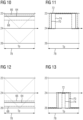
- FIGS 10 and 11 show in schematic diagrams how the FIG 4 and 5 the conditions when a large superimposed voltage is superimposed on the respective nominal voltage signals 64, 66, 68.
- the corresponding phase voltages 70, 72, 74 are shown FIG 11 .
- the FIGS 12 and 13 show a corresponding situation in which the superposition voltage is negative, that is, the electrical potentials of the setpoint voltage signals 64, 66, 68 are between the electrical potentials 24, 26.
- the corresponding phase voltages 70, 72, 74 are in FIG 13 shown.
- FIGS 14 and 15 an intermediate value of the superimposed voltage is shown, from which it can be seen that the superimposed voltage can also change continuously, whereby the load of the switching elements 40 to 56 can also be changed, preferably continuously.
- the FIGS 14 and 15 represent an intermediate value, as it relates to the scenarios according to the FIGS 10 to 13 has already been explained.
- FIG 16 shows the target voltage signals 64, 66, 68 superimposed by a superimposed voltage signal 86, which is trapezoidal, using corresponding graphs 94, 96, 98, how they can change over time due to the superimposed voltages.
- the superimposed voltages are formed by trapezoidal alternating voltages whose frequency is greater than the frequency of the phase voltages 64, 66, 68.
- the superimposed alternating voltage signal 86 is therefore trapezoidal here, for example.
- FIG 17 shows a corresponding schematic diagram representation like FIG 16 , in which the superimposed voltage signal 86 has an approximately rectangular signal shape, with the corners being rounded.
- FIG 18 shows in a further embodiment the superposition voltage due to a superposition voltage signal 86, which has an approximately sinusoidal signal shape.
- the frequency of the superimposed alternating voltage signals does not have to be constant. It can of course be varied as required, for example depending on the design of the three-level inverter 28, a current load condition and/or the like.
- FIG 19 shows in a further schematic diagram the temporal courses of the target voltage signals 64, 68, 66 as well as the courses of the respective target voltage signals superimposed by the superimposed voltage with correspondingly assigned graphs 88, 90, 92, as shown in accordance with FIG 16 It can be seen that all of the target voltage signals 64, 66, 68 are potential-shifted in accordance with the superimposed voltage signal 86, so that the corresponding circuit arrangements 58, 60, 62 are loaded more evenly.
- FIG 20 shows in a voltage-time diagram the corresponding superimposed voltage signal 86, which has an amplitude 84.
- the switching element at which the highest temperature occurs usually limits the current carrying capacity of the entire inverter or multi-level energy converter. If all phase voltages are shifted by the same amount, the interlinked voltages remain the same, so that effects on the electrical machine are negligible.
- the distribution of the conduction losses across the various switching elements of the multi-level energy converter can be influenced.
- its temperature can be reduced at the same current.
- the maximum permissible temperature of this switching element is therefore only reached at a higher current.
- the shift in the target voltage signals can be carried out continuously and this can also result in a continuous change in the distribution of losses.
- the ripple current can be reduced because no timing gaps are required.
- the frequency that is decisive for the ripple current for example, remains twice the pulse frequency over the entire period of the fundamental oscillation.
- Common mode currents are usually proportional to a capacitance in the common mode circuit and to the rate of change of a common mode voltage. This can be very large when using the timing gap because it usually corresponds to the switching speed of the switching elements and these should switch as quickly as possible to achieve low switching losses. In the method described here according to the invention, however, the rate of change of the common mode voltage is decoupled from the switching behavior of the switching elements and can be freely adjusted.
- the first DC intermediate circuit 12 provides the first DC intermediate circuit voltage U1 and the second DC intermediate circuit 14 provides the second DC intermediate circuit voltage U1.
- the first and second DC intermediate circuit voltages U1, U2 are the same.
- FIG 21 shows in a schematic diagram the effects that can be achieved with the operating method according to the invention.
- the abscissa is assigned to the frequency, whereas the ordinate is assigned to the electrical current.
- the graphs 100, 102, 104, 106 shown show the maximum current carrying capacities of the switching elements 40 to 56 and thus also of the multi-level energy converter or the three-point inverter 28.
- a graph 104 shows a derating for the intended operating case without using a superimposed voltage, whereby a temperature ripple is not taken into account.
- Graph 104 shows that the permissible current carrying capacity also decreases with decreasing frequency.
- Graph 106 shows the situation for the case of the maximum permissible junction temperature of each of the switching elements 40 to 56 in conjunction with a temperature ripple permissible for the specified service life.
- the temperature ripple refers to a temperature swing during a period of the fundamental oscillation of the target voltage signals 64, 66, 68. The longer the overload times, the more derating is required. This can be shown using graphs 104 and 106.
- Graphs 100 and 102 now show the situation using a superimposed voltage. With regard to the operating conditions, graph 100 is assigned to graph 104 and graph 102 to graph 106. It can be seen that the load capacity of the multi-level energy converter or three-point inverter 28 can be significantly increased by using the superimposed voltage, particularly in the range of frequencies that are less than about 30 Hz. However, this can also vary depending on the design of the multi-level energy converter or three-point inverter 28, because the effect of the invention can also depend, among other things, on how the design of the multi-level energy converter or three-point inverter 28 is actually implemented.
Landscapes
- Engineering & Computer Science (AREA)
- Power Engineering (AREA)
- Inverter Devices (AREA)
Claims (10)
- Procédé pour faire fonctionner des éléments (40 à 56) de commutation d'un convertisseur (28) d'énergie à plusieurs niveaux, utilisant au moins trois potentiels (22, 24, 26) électriques et auquel est raccordée une machine (30) électrique polyphasée, dans lequel on fait fonctionner des éléments (40 à 56) de commutation du convertisseur (28) d'énergie à plusieurs niveaux au moyen de signaux (70, 72, 74) de commutation correspondants dans un fonctionnement cadencé donné à l'avance, dans lequel on détermine les signaux (70, 72, 74) de commutation pour les éléments (40 à 56) de commutation affectés à l'une respective des phases (U, V, W), en fonction d'un signal (64, 66, 68) de tension de consigne respectif, afin d'appliquer, à chaque phase de la machine (30) électrique polyphasée, une tension (70, 72, 74) de phase respective, dans lequel on détermine les signaux de commutation supplémentairement en fonction d'un signal (86) de tension de superposition donné à l'avance, de manière à superposer, aux tensions (70, 72, 74) respectives de phase, une tension de superposition, qui dépend du signal (86) de tension de superposition, dans lequel on utilise comme signal (86) de tension de superposition un signal de tension alternative, dans lequel on forme le signal de tension alternative, de manière à ce que la charge se répartisse cycliquement sur les potentiels (22, 24, 26) électriques et leurs éléments (40 à 56) de commutation, dans lequel en décalant les tensions (70, 72, 74) respectives de phase on répartit, en raison de la tension de superposition, une charge des éléments (40 à 56) de commutation uniformément sur l'ensemble des éléments (40 à 56) de commutation du convertisseur (28) d'énergie à plusieurs niveaux, dans lequel le signal de tension alternative est un signal sinusoïdal ou trapézoïdal de tension alternative.
- Procédé suivant la revendication 1, caractérisé en ce que la superposition a lieu, lorsqu'une fréquence des signaux (64, 66, 68) de tension de consigne est plus basse qu'une fréquence de comparaison donnée à l'avance.
- Procédé suivant l'une des revendications précédentes, caractérisé en ce que la superposition a lieu, lorsqu'une amplitude des signaux (64, 66, 68) de tension de consigne est plus petite qu'une amplitude de comparaison donnée à l'avance.
- Procédé suivant l'une des revendications précédentes, caractérisé en ce que l'on détermine des températures des éléments (40 à 56) de commutation et on règle le signal (86) de tension de superposition en fonction des températures déterminées.
- Procédé suivant l'une des revendications précédentes, caractérisé en ce que l'on détermine des états de vieillissement des éléments (40 à 56) de commutation et on règle le signal (86) de tension de superposition en fonction des états de vieillissement déterminés.
- Procédé suivant l'une des revendications précédentes, caractérisé en ce que l'on règle une amplitude et/ou une fréquence du signal de tension alternative en fonction d'une constante de temps thermique des éléments (40 à 56) de commutation.
- Procédé suivant l'une des revendications précédentes, caractérisé en ce que le signal de tension alternative est un signal trapézoïdal de tension alternative.
- Unité (38) de commande pour la commande d'éléments (40 à 56) de commutation d'un convertisseur (28) d'énergie à plusieurs niveaux utilisant au moins trois potentiels (22, 24, 26) électriques et constitué pour se raccorder à une machine (30) électrique polyphasée, dans laquelle l'unité (38) de commande est constituée pour faire fonctionner les éléments (40 à 56) de commutation du convertisseur (28) d'énergie à plusieurs niveaux au moyen de signaux (70, 72, 74) de commutation correspondants dans un fonctionnement cadencé donné à l'avance, à quelle fin l'unité (38) de commande détermine les signaux (70, 72, 74) de commutation pour les éléments (40 à 56) de commande affectés à une respective des phases en fonction d'un signal (64, 66, 68) respectif de tension de consigne, afin d'appliquer, à chaque phase (U, V, W) de la machine (30) électrique polyphasée, une tension (70, 72, 74) respective de phase, dans laquelle l'unité (38) de commande est constituée en outre pour déterminer les signaux (70, 72, 74) de commutation supplémentairement en fonction d'un signal (86) de tension de superposition donné à l'avance, afin de superposer, aux tensions (64, 66, 68) respectives de phase, une tension de superposition, qui dépend du signal (86) de tension de superposition, caractérisée en ce que l'unité (38) de commande est constituée pour effectuer un procédé suivant l'une des revendications 1 à 7.
- Convertisseur (28) d'énergie à plusieurs niveaux, qui est constitué pour se raccorder à une machine (30) électrique polyphasée et qui utilise au moins trois potentiels (22, 24, 26) électriques comprenant :- des éléments (40 à 56) de commutation pour l'application d'une tension (70, 72, 74) respective de phase à chaque phase (U, V, W) de la machine (30) électrique polyphasée et- une unité (38) de commande pour la commande des éléments (40 à 56) de commutation dans un fonctionnement cadencé donné à l'avance, au moyen de signaux de commutation correspondants,caractérisé en ce que l'unité (38) de commande est constituée suivant la revendication 8.
- Dispositif (10) d'entraînement comprenant :- une machine (30) électrique polyphasée et- un convertisseur (28) d'énergie à plusieurs niveaux, qui est raccordé à la machine (30) électrique polyphasée et qui utilise au moins trois potentiels (22, 24, 26) électriques,caractérisé en ce que le convertisseur (28) d'énergie à plusieurs niveaux est constitué suivant la revendication 9.
Applications Claiming Priority (2)
| Application Number | Priority Date | Filing Date | Title |
|---|---|---|---|
| EP19153054.2A EP3687059A1 (fr) | 2019-01-22 | 2019-01-22 | Fonctionnement des éléments de commutation d'un convertisseur d'énergie multiniveau |
| PCT/EP2019/085600 WO2020151883A1 (fr) | 2019-01-22 | 2019-12-17 | Fonctionnement d'éléments de commutation d'un convertisseur d'énergie à niveaux multiples |
Publications (3)
| Publication Number | Publication Date |
|---|---|
| EP3868016A1 EP3868016A1 (fr) | 2021-08-25 |
| EP3868016C0 EP3868016C0 (fr) | 2024-11-27 |
| EP3868016B1 true EP3868016B1 (fr) | 2024-11-27 |
Family
ID=65200636
Family Applications (2)
| Application Number | Title | Priority Date | Filing Date |
|---|---|---|---|
| EP19153054.2A Withdrawn EP3687059A1 (fr) | 2019-01-22 | 2019-01-22 | Fonctionnement des éléments de commutation d'un convertisseur d'énergie multiniveau |
| EP19829092.6A Active EP3868016B1 (fr) | 2019-01-22 | 2019-12-17 | Fonctionnement des éléments de commutation d'un convertisseur d'énergie multiniveau |
Family Applications Before (1)
| Application Number | Title | Priority Date | Filing Date |
|---|---|---|---|
| EP19153054.2A Withdrawn EP3687059A1 (fr) | 2019-01-22 | 2019-01-22 | Fonctionnement des éléments de commutation d'un convertisseur d'énergie multiniveau |
Country Status (4)
| Country | Link |
|---|---|
| US (1) | US11356032B2 (fr) |
| EP (2) | EP3687059A1 (fr) |
| CN (1) | CN113348621B (fr) |
| WO (1) | WO2020151883A1 (fr) |
Families Citing this family (2)
| Publication number | Priority date | Publication date | Assignee | Title |
|---|---|---|---|---|
| DE102023208477A1 (de) * | 2023-09-04 | 2025-03-06 | Robert Bosch Gesellschaft mit beschränkter Haftung | Invertereinheit |
| DE102023126797A1 (de) * | 2023-10-02 | 2025-04-03 | Cariad Se | Digitale Implementierung von synchroner Taktung / Ansteuerung von Elektromotoren |
Citations (1)
| Publication number | Priority date | Publication date | Assignee | Title |
|---|---|---|---|---|
| WO2019137916A1 (fr) * | 2018-01-11 | 2019-07-18 | Abb Schweiz Ag | Commande prédictive de modèle d'un convertisseur basée sur des motifs de commutation à modulation de largeur d'impulsion |
Family Cites Families (27)
| Publication number | Priority date | Publication date | Assignee | Title |
|---|---|---|---|---|
| JP2884880B2 (ja) * | 1992-02-12 | 1999-04-19 | 株式会社日立製作所 | 電力変換器の制御装置 |
| DE50110556D1 (de) * | 2000-09-13 | 2006-09-07 | Abb Research Ltd | Steuer- und regelverfahren für einen dreipunkt-stromrichter mit aktiven klemmschaltern sowie vorrichtung hierzu |
| KR100661107B1 (ko) * | 2003-03-12 | 2006-12-26 | 미쓰비시덴키 가부시키가이샤 | 전동기 제어장치 |
| JP4436843B2 (ja) * | 2007-02-07 | 2010-03-24 | 株式会社日立製作所 | 電力変換装置 |
| US7843156B2 (en) * | 2007-06-28 | 2010-11-30 | Gm Global Technology Operations, Inc. | Method and apparatus for active voltage control of electric motors |
| IT1396963B1 (it) * | 2009-10-20 | 2012-12-20 | Meta System Spa | Sistema e metodo per la compensazione dello sbilanciamento delle tensioni in ingresso in inverter multilivello o simili |
| JP5380376B2 (ja) * | 2010-06-21 | 2014-01-08 | 日立オートモティブシステムズ株式会社 | パワー半導体装置 |
| US8441820B2 (en) * | 2010-09-29 | 2013-05-14 | General Electric Company | DC-link voltage balancing system and method for multilevel converters |
| FR2985616B1 (fr) * | 2012-01-09 | 2014-02-14 | Converteam Technology Ltd | Compensateur d'energie reactive et procede d'equilibrage de tensions de demi-bus associe |
| US8786232B2 (en) * | 2012-04-20 | 2014-07-22 | Hamilton Sundstrand Corporation | Thermal stress reduction in aircraft motor controllers |
| ES2718807T3 (es) * | 2012-06-07 | 2019-07-04 | Abb Research Ltd | Procedimiento de amortiguación de secuencia cero y equilibrado de tensión en un convertidor de tres niveles con condensadores de enlace de CC divididos y filtro LCL virtualmente conectado a tierra |
| CN103825474B (zh) * | 2012-11-16 | 2016-08-31 | 台达电子工业股份有限公司 | 低共模噪声的电源变换装置及其应用系统 |
| CN104798297B (zh) * | 2012-11-21 | 2018-04-17 | 奥的斯电梯公司 | 中性点箝位多电平转换器 |
| KR20140066063A (ko) * | 2012-11-22 | 2014-05-30 | 삼성전자주식회사 | 모터 구동장치 및 그 제어방법 |
| US9274159B2 (en) * | 2013-07-16 | 2016-03-01 | GM Global Technology Operations LLC | Method and apparatus for monitoring an electric power circuit |
| EP2849331B1 (fr) * | 2013-09-11 | 2020-02-12 | ABB Schweiz AG | Procédé et appareil d'équilibrage de tensions de liaison à courant continu d'un onduleur à niveaux multiples |
| WO2015094232A1 (fr) * | 2013-12-18 | 2015-06-25 | Otis Elevator Company | Stratégies de commande d'un dispositif d'entraînement régénératif de ligne multi-niveaux |
| CN104811073B (zh) | 2014-01-24 | 2019-05-31 | 通用电气能源电能变换科技有限公司 | 变换器模块、装置、系统和相关方法 |
| CN105099241B (zh) * | 2014-04-18 | 2019-03-19 | 通用电气公司 | 控制器、电能变换系统和方法 |
| CN104052323B (zh) * | 2014-07-02 | 2017-08-04 | 南京理工大学 | 基于功率因数角的中点电压平衡控制系统及方法 |
| GB201506183D0 (en) * | 2015-04-23 | 2015-05-27 | Rolls Royce Plc | Inverter control method |
| US9698722B2 (en) * | 2015-06-19 | 2017-07-04 | Deere & Company | Method and inverter with thermal management for controlling an electric machine |
| GB2545236B (en) * | 2015-12-10 | 2017-12-13 | Rolls Royce Plc | A method of controlling an inverter |
| CN107196536B (zh) * | 2017-05-03 | 2019-04-02 | 浙江大学 | 一种具有中点平衡和共模电压抑制能力的三电平svpwm方法 |
| JP6753837B2 (ja) * | 2017-12-18 | 2020-09-09 | 株式会社東芝 | インバータ装置、及びインバータ装置の放熱特性検出方法 |
| JP6907171B2 (ja) * | 2018-09-25 | 2021-07-21 | 株式会社Soken | 回転電機の駆動装置 |
| US20200251981A1 (en) * | 2019-02-05 | 2020-08-06 | Hamilton Sundstrand Corporation | Three-level pulse width modulation technique for reducing semiconductor short circuit conduction loss |
-
2019
- 2019-01-22 EP EP19153054.2A patent/EP3687059A1/fr not_active Withdrawn
- 2019-12-17 CN CN201980089909.XA patent/CN113348621B/zh active Active
- 2019-12-17 WO PCT/EP2019/085600 patent/WO2020151883A1/fr not_active Ceased
- 2019-12-17 EP EP19829092.6A patent/EP3868016B1/fr active Active
- 2019-12-17 US US17/424,390 patent/US11356032B2/en active Active
Patent Citations (1)
| Publication number | Priority date | Publication date | Assignee | Title |
|---|---|---|---|---|
| WO2019137916A1 (fr) * | 2018-01-11 | 2019-07-18 | Abb Schweiz Ag | Commande prédictive de modèle d'un convertisseur basée sur des motifs de commutation à modulation de largeur d'impulsion |
Also Published As
| Publication number | Publication date |
|---|---|
| US11356032B2 (en) | 2022-06-07 |
| US20220094278A1 (en) | 2022-03-24 |
| EP3687059A1 (fr) | 2020-07-29 |
| EP3868016C0 (fr) | 2024-11-27 |
| EP3868016A1 (fr) | 2021-08-25 |
| CN113348621B (zh) | 2024-10-29 |
| CN113348621A (zh) | 2021-09-03 |
| WO2020151883A1 (fr) | 2020-07-30 |
Similar Documents
| Publication | Publication Date | Title |
|---|---|---|
| DE102021003941B4 (de) | Elektrisches Antriebssystem sowie Verfahren | |
| DE102015214768A1 (de) | Steuervorrichtung für eine rotationsmaschine | |
| DE102015121226A1 (de) | Umrichter, Elektrisches Polyphasensystem und Verfahren | |
| DE102011003352A1 (de) | Verfahren, Systeme und Vorrichtung zur Optimierung von Dritte-Harmonische-Strominjektion in einer mehrphasigen Maschine | |
| EP2522069A2 (fr) | Circuiterie pour convertisseurs de courant d'entraînement modulaires | |
| WO2017174102A1 (fr) | Module pour convertisseur à plusieurs niveaux | |
| DE112016003290T5 (de) | Leistungswandler | |
| EP2786462A2 (fr) | Procédé de commande d'un convertisseur multiphase | |
| EP2730021B1 (fr) | Procédé de commande d'une machine polyphasée | |
| DE102011116593B4 (de) | Wechselrichter mit asymmetrischen Drosseln und einer Steuereinheit zum asymmetrischen Betrieb der Drosseln | |
| DE102014211853A1 (de) | Spannungskonverter und Verfahren zum Konvertieren einer elektrischen Spannung | |
| WO2023147965A1 (fr) | Système et procédé d'entraînement électrique | |
| EP3868016B1 (fr) | Fonctionnement des éléments de commutation d'un convertisseur d'énergie multiniveau | |
| DE102017115639A1 (de) | Reduzierung des Rippelstroms bei Schaltvorgängen einer Brückenschaltung | |
| DE3131361C2 (fr) | ||
| WO2013110501A2 (fr) | Procédé pour commander un moteur bldc | |
| EP3605821B1 (fr) | Onduleur direct autoguidé et procédé de commande pour l'onduleur direct autoguidé | |
| WO2018019944A1 (fr) | Convertisseur d'entraînement pour machine à reluctance commutée | |
| DE102019208559A1 (de) | Betreiben von Schaltelementen eines Wechselrichters | |
| EP3095178B1 (fr) | Circuit de convertisseur modulaire doté de sous-modules fonctionnant en mode linéaire | |
| EP3672058A1 (fr) | Fonctionnement des éléments de commutation d'un onduleur d'un véhicule entrainé au moyen d'au moins une machine synchrone au moins triphasée, en particulier ferroviaire | |
| DE102023200118A1 (de) | Stromrichter und Schaltungsanordnung mit einem solchen Stromrichter | |
| DE102014007632B4 (de) | Verfahren zum Regeln einer elektrischen Maschine | |
| DE102007040166B4 (de) | Motorsteuerungsvorrichtung | |
| DE102013220940A1 (de) | Wechselrichter |
Legal Events
| Date | Code | Title | Description |
|---|---|---|---|
| STAA | Information on the status of an ep patent application or granted ep patent |
Free format text: STATUS: UNKNOWN |
|
| STAA | Information on the status of an ep patent application or granted ep patent |
Free format text: STATUS: THE INTERNATIONAL PUBLICATION HAS BEEN MADE |
|
| PUAI | Public reference made under article 153(3) epc to a published international application that has entered the european phase |
Free format text: ORIGINAL CODE: 0009012 |
|
| STAA | Information on the status of an ep patent application or granted ep patent |
Free format text: STATUS: REQUEST FOR EXAMINATION WAS MADE |
|
| 17P | Request for examination filed |
Effective date: 20210517 |
|
| AK | Designated contracting states |
Kind code of ref document: A1 Designated state(s): AL AT BE BG CH CY CZ DE DK EE ES FI FR GB GR HR HU IE IS IT LI LT LU LV MC MK MT NL NO PL PT RO RS SE SI SK SM TR |
|
| DAV | Request for validation of the european patent (deleted) | ||
| DAX | Request for extension of the european patent (deleted) | ||
| STAA | Information on the status of an ep patent application or granted ep patent |
Free format text: STATUS: EXAMINATION IS IN PROGRESS |
|
| 17Q | First examination report despatched |
Effective date: 20230301 |
|
| REG | Reference to a national code |
Ref country code: DE Ref legal event code: R079 Ipc: H02P0027140000 Ref country code: DE Ref legal event code: R079 Ref document number: 502019012569 Country of ref document: DE Free format text: PREVIOUS MAIN CLASS: H02P0027040000 Ipc: H02P0027140000 |
|
| GRAP | Despatch of communication of intention to grant a patent |
Free format text: ORIGINAL CODE: EPIDOSNIGR1 |
|
| STAA | Information on the status of an ep patent application or granted ep patent |
Free format text: STATUS: GRANT OF PATENT IS INTENDED |
|
| RIC1 | Information provided on ipc code assigned before grant |
Ipc: H02M 1/32 20070101ALN20240729BHEP Ipc: H02M 7/483 20070101ALI20240729BHEP Ipc: H02P 1/16 20060101ALI20240729BHEP Ipc: H02P 27/14 20060101AFI20240729BHEP |
|
| INTG | Intention to grant announced |
Effective date: 20240814 |
|
| GRAS | Grant fee paid |
Free format text: ORIGINAL CODE: EPIDOSNIGR3 |
|
| GRAA | (expected) grant |
Free format text: ORIGINAL CODE: 0009210 |
|
| STAA | Information on the status of an ep patent application or granted ep patent |
Free format text: STATUS: THE PATENT HAS BEEN GRANTED |
|
| AK | Designated contracting states |
Kind code of ref document: B1 Designated state(s): AL AT BE BG CH CY CZ DE DK EE ES FI FR GB GR HR HU IE IS IT LI LT LU LV MC MK MT NL NO PL PT RO RS SE SI SK SM TR |
|
| REG | Reference to a national code |
Ref country code: GB Ref legal event code: FG4D Free format text: NOT ENGLISH |
|
| REG | Reference to a national code |
Ref country code: CH Ref legal event code: EP |
|
| REG | Reference to a national code |
Ref country code: IE Ref legal event code: FG4D Free format text: LANGUAGE OF EP DOCUMENT: GERMAN |
|
| REG | Reference to a national code |
Ref country code: DE Ref legal event code: R096 Ref document number: 502019012569 Country of ref document: DE |
|
| U01 | Request for unitary effect filed |
Effective date: 20241127 |
|
| U07 | Unitary effect registered |
Designated state(s): AT BE BG DE DK EE FI FR IT LT LU LV MT NL PT RO SE SI Effective date: 20241203 |
|
| U20 | Renewal fee for the european patent with unitary effect paid |
Year of fee payment: 6 Effective date: 20241219 |
|
| PG25 | Lapsed in a contracting state [announced via postgrant information from national office to epo] |
Ref country code: IS Free format text: LAPSE BECAUSE OF FAILURE TO SUBMIT A TRANSLATION OF THE DESCRIPTION OR TO PAY THE FEE WITHIN THE PRESCRIBED TIME-LIMIT Effective date: 20250327 Ref country code: HR Free format text: LAPSE BECAUSE OF FAILURE TO SUBMIT A TRANSLATION OF THE DESCRIPTION OR TO PAY THE FEE WITHIN THE PRESCRIBED TIME-LIMIT Effective date: 20241127 |
|
| PG25 | Lapsed in a contracting state [announced via postgrant information from national office to epo] |
Ref country code: ES Free format text: LAPSE BECAUSE OF FAILURE TO SUBMIT A TRANSLATION OF THE DESCRIPTION OR TO PAY THE FEE WITHIN THE PRESCRIBED TIME-LIMIT Effective date: 20241127 |
|
| PG25 | Lapsed in a contracting state [announced via postgrant information from national office to epo] |
Ref country code: NO Free format text: LAPSE BECAUSE OF FAILURE TO SUBMIT A TRANSLATION OF THE DESCRIPTION OR TO PAY THE FEE WITHIN THE PRESCRIBED TIME-LIMIT Effective date: 20250227 |
|
| PG25 | Lapsed in a contracting state [announced via postgrant information from national office to epo] |
Ref country code: GR Free format text: LAPSE BECAUSE OF FAILURE TO SUBMIT A TRANSLATION OF THE DESCRIPTION OR TO PAY THE FEE WITHIN THE PRESCRIBED TIME-LIMIT Effective date: 20250228 |
|
| PG25 | Lapsed in a contracting state [announced via postgrant information from national office to epo] |
Ref country code: PL Free format text: LAPSE BECAUSE OF FAILURE TO SUBMIT A TRANSLATION OF THE DESCRIPTION OR TO PAY THE FEE WITHIN THE PRESCRIBED TIME-LIMIT Effective date: 20241127 |
|
| PG25 | Lapsed in a contracting state [announced via postgrant information from national office to epo] |
Ref country code: RS Free format text: LAPSE BECAUSE OF FAILURE TO SUBMIT A TRANSLATION OF THE DESCRIPTION OR TO PAY THE FEE WITHIN THE PRESCRIBED TIME-LIMIT Effective date: 20250227 |
|
| PG25 | Lapsed in a contracting state [announced via postgrant information from national office to epo] |
Ref country code: SM Free format text: LAPSE BECAUSE OF FAILURE TO SUBMIT A TRANSLATION OF THE DESCRIPTION OR TO PAY THE FEE WITHIN THE PRESCRIBED TIME-LIMIT Effective date: 20241127 |
|
| PG25 | Lapsed in a contracting state [announced via postgrant information from national office to epo] |
Ref country code: SK Free format text: LAPSE BECAUSE OF FAILURE TO SUBMIT A TRANSLATION OF THE DESCRIPTION OR TO PAY THE FEE WITHIN THE PRESCRIBED TIME-LIMIT Effective date: 20241127 |
|
| PG25 | Lapsed in a contracting state [announced via postgrant information from national office to epo] |
Ref country code: CZ Free format text: LAPSE BECAUSE OF FAILURE TO SUBMIT A TRANSLATION OF THE DESCRIPTION OR TO PAY THE FEE WITHIN THE PRESCRIBED TIME-LIMIT Effective date: 20241127 |
|
| REG | Reference to a national code |
Ref country code: CH Ref legal event code: PL |
|
| PG25 | Lapsed in a contracting state [announced via postgrant information from national office to epo] |
Ref country code: MC Free format text: LAPSE BECAUSE OF FAILURE TO SUBMIT A TRANSLATION OF THE DESCRIPTION OR TO PAY THE FEE WITHIN THE PRESCRIBED TIME-LIMIT Effective date: 20241127 |
|
| PLBE | No opposition filed within time limit |
Free format text: ORIGINAL CODE: 0009261 |
|
| STAA | Information on the status of an ep patent application or granted ep patent |
Free format text: STATUS: NO OPPOSITION FILED WITHIN TIME LIMIT |
|
| PG25 | Lapsed in a contracting state [announced via postgrant information from national office to epo] |
Ref country code: CH Free format text: LAPSE BECAUSE OF NON-PAYMENT OF DUE FEES Effective date: 20241231 |
|
| PG25 | Lapsed in a contracting state [announced via postgrant information from national office to epo] |
Ref country code: IE Free format text: LAPSE BECAUSE OF NON-PAYMENT OF DUE FEES Effective date: 20241217 |
|
| GBPC | Gb: european patent ceased through non-payment of renewal fee |
Effective date: 20250227 |
|
| 26N | No opposition filed |
Effective date: 20250828 |
|
| PG25 | Lapsed in a contracting state [announced via postgrant information from national office to epo] |
Ref country code: GB Free format text: LAPSE BECAUSE OF NON-PAYMENT OF DUE FEES Effective date: 20250227 |
|
| U20 | Renewal fee for the european patent with unitary effect paid |
Year of fee payment: 7 Effective date: 20251219 |