EP3868191A1 - Dispositif agricole pourvu d éléments paliers élastiques différents - Google Patents
Dispositif agricole pourvu d éléments paliers élastiques différents Download PDFInfo
- Publication number
- EP3868191A1 EP3868191A1 EP21155029.8A EP21155029A EP3868191A1 EP 3868191 A1 EP3868191 A1 EP 3868191A1 EP 21155029 A EP21155029 A EP 21155029A EP 3868191 A1 EP3868191 A1 EP 3868191A1
- Authority
- EP
- European Patent Office
- Prior art keywords
- group
- leaf spring
- spring elements
- row units
- agricultural device
- Prior art date
- Legal status (The legal status is an assumption and is not a legal conclusion. Google has not performed a legal analysis and makes no representation as to the accuracy of the status listed.)
- Granted
Links
Images


Classifications
-
- A—HUMAN NECESSITIES
- A01—AGRICULTURE; FORESTRY; ANIMAL HUSBANDRY; HUNTING; TRAPPING; FISHING
- A01B—SOIL WORKING IN AGRICULTURE OR FORESTRY; PARTS, DETAILS, OR ACCESSORIES OF AGRICULTURAL MACHINES OR IMPLEMENTS, IN GENERAL
- A01B61/00—Devices for, or parts of, agricultural machines or implements for preventing overstrain
- A01B61/04—Devices for, or parts of, agricultural machines or implements for preventing overstrain of the connection between tools and carrier beam or frame
- A01B61/044—Devices for, or parts of, agricultural machines or implements for preventing overstrain of the connection between tools and carrier beam or frame the connection enabling a yielding pivoting movement around a substantially horizontal and transverse axis
-
- A—HUMAN NECESSITIES
- A01—AGRICULTURE; FORESTRY; ANIMAL HUSBANDRY; HUNTING; TRAPPING; FISHING
- A01C—PLANTING; SOWING; FERTILISING
- A01C7/00—Sowing
- A01C7/20—Parts of seeders for conducting and depositing seed
- A01C7/201—Mounting of the seeding tools
Definitions
- the invention relates to an agricultural device, preferably a sowing and / or soil cultivating machine, with a support structure and a large number of row units that are expediently arranged next to one another.
- Agricultural row units such as B. coulters are usually stored (suspended) on support structures of agricultural tillage and / or seed drills.
- the storage is usually carried out in such a way that, on the one hand, the row units can swivel upwards when driving over obstacles (e.g. stones) and, on the other hand, can be moved along the arable area with a defined pre-tensioning / contact force to maintain a defined working depth.
- the storage is usually carried out so that they can, for. B. can also at least largely absorb high-frequency oscillating and shock movements.
- a common storage in the form of a so-called rubber cord storage is z. B. in the DE 10 2009 058 342 A1 disclosed.
- the individual row units are equipped with identical rubber cord bearings. It is often desirable to arrange the row units offset to one another in the direction of travel and / or in their longitudinal direction, so that, alternately, some row units protrude far and some row units short from their support structure. However, this has the consequence that the row units protruding at different distances have different contact forces and / or working depths.
- One object of the invention is to create an improved and / or alternative agricultural device, in particular an agricultural device, with which essentially the same contact forces (in particular pretensioning forces) and / or working depths can be made possible despite differently positioned row units.
- the invention relates to an agricultural device, preferably a sowing and / or soil cultivating machine, e.g. B. a disc harrow, a cultivator, a precision seeder, a drill, etc.
- a sowing and / or soil cultivating machine e.g. B. a disc harrow, a cultivator, a precision seeder, a drill, etc.
- the agricultural device comprises a support structure, e.g. B. a coulter rail.
- the agricultural device comprises a first group of row units, wherein the row units of the first group are connected to the support structure by means of elastic connecting elements (preferably are attached to it, expediently directly or indirectly), and a second group of row units, the row units of the second group by means of elastic connecting elements are connected to the support structure (preferably mounted thereon, expediently directly or indirectly).
- the agricultural device is particularly characterized in that the connecting elements of the first group and the connecting elements of the second group are preferably designed as leaf spring elements and have different elasticities (e.g. stiffness, bending stiffness, hardness and / or spring characteristics).
- the connecting elements of the first group and the connecting elements of the second group are preferably designed as leaf spring elements and have different elasticities (e.g. stiffness, bending stiffness, hardness and / or spring characteristics).
- contact forces in particular pretensioning forces
- / or working depths of the row units of the first group and of the second group can advantageously be substantially adapted to one another, in particular substantially adapted to one another.
- the leaf spring elements of the first group on the one hand and the leaf spring elements of the second group on the other hand have different elasticities (e.g. stiffness, bending stiffness, hardness and / or spring characteristics), e.g. B. the leaf spring elements of the second group are made stiffer and / or harder than the leaf spring elements of the first group.
- the leaf spring elements of the first group and / or the leaf spring elements of the second group preferably form bearing elements for (in particular direct or indirect) mounting, preferably pivot mounting, on the support structure.
- leaf spring elements e.g. to geometry, lever length, load, etc.
- elastic properties of the leaf spring elements e.g. to geometry, lever length, load, etc.
- leaf spring elements of the second group provide a higher rigidity (for example flexural rigidity) and / or are made harder than the leaf spring elements of the first group.
- the leaf spring elements of the first group and / or the leaf spring elements of the second group can, for example, have one or more leaves, e.g. B. with essentially constant or changing cross section along its longitudinal direction, in particular continuously and / or stepwise changing cross section.
- the leaf spring elements of the first group and the second group can preferably be pretensioned in a predetermined position, but at the same time allow in particular a pivoting (suspension) of the row units.
- a desired ground pressure and / or a desired working depth can be achieved, but on the other hand, pivoting and thus evasion of the ground tools or generally the row units when driving onto a stone, for example, can be made possible.
- the leaf spring elements of the second group can, for. B. at least partially wider and / or thicker (z. B. single or multi-layer) than the leaf spring elements of the first group, preferably to achieve the different elasticities.
- the leaf spring elements of the first group and / or the second can, for. B. have a material width and / or material thickness that changes continuously at least in sections over its longitudinal extent.
- embodiments with an essentially constant material width and / or material thickness are also possible.
- leaf spring elements of the second group may have larger or smaller arc or curvature sizes (e.g. radii) than the leaf spring elements of the first group, preferably to achieve the different elasticities.
- the leaf spring elements of the second group and the leaf spring elements of the first group can, for. B. made of different materials or different material compositions, preferably to achieve the different elasticities.
- leaf spring elements of the first group and / or the leaf spring elements of the second group are made from a metallic material, from a plastic material or from a composite material.
- the leaf spring elements of the first group and / or the leaf spring elements of the second group can, for. B. made of fiber-reinforced (especially long fiber-reinforced) plastic.
- the leaf spring elements of the first group and / or the leaf spring elements of the second group can, for. B. plastic layers with different matrix arrangement, z. B. different fiber orientation, fiber density, fiber thickness, etc., preferably to achieve the different elasticities.
- the leaf spring elements of the first group and the leaf spring elements of the second group are equipped with at least one hard material insert and / or hard material attachment, preferably at bearing and / or force introduction points.
- the hard material insert and / or hard material attachment is in particular harder than the plastic surrounding it and z. B. made of metallic material.
- the hard material insert and / or the hard material attachment can, for. B. comprise a plate-shaped support surface, a bearing sleeve and / or threaded sleeve.
- the hard material insert and / or the hard material attachment can, for. B. be raised with respect to surrounding plastic material, z. B. as a storage and / or support surface.
- the leaf spring elements of the first group and the second group are designed so that an at least almost linear, curved or degressive force-displacement curve can be established therein when the associated row unit of the first group and / or the second group (e.g. when driving over an obstacle (e.g. a stone)) relative to the support structure is pivoted upwards.
- the elasticity properties can be appropriately adapted (e.g. adaptation of shape, thickness, width, matrix arrangement, plastic layer structure, fiber density, hardness, stiffness, fiber strength, fiber orientation, etc.).
- the connecting elements of the first group and the connecting elements of the second group can, for. B. have a locally modified plastic layer structure and / or a locally modified plastic matrix, preferably at bearing and / or force introduction points.
- the bearing and / or force introduction points can advantageously be reinforced.
- the row units of the first group each have a support arm body (e.g. coulter body) to which the leaf spring elements of the first group are mounted by means of a fastening device (e.g. screwed) or with which the leaf spring elements of the first group are integral -integrally designed.
- a support arm body e.g. coulter body
- a fastening device e.g. screwed
- the row units of the second group can preferably also each have a support arm body (e.g. coulter body) to which the leaf spring elements of the second group are mounted by means of a fastening device (e.g. screwed) or with which the leaf spring elements of the second group are made in one piece are trained.
- a support arm body e.g. coulter body
- a fastening device e.g. screwed
- the leaf spring elements of the first group can, for. B. be designed as a one-piece, integral part of the support arm bodies of the first group.
- the leaf spring elements of the second group can, for. B. be designed as a one-piece, integral part of the support arm bodies of the second group.
- the support arm bodies of the first group and / or the second group can, for. B. made of metallic material, plastic material or a composite material, preferably fiber-reinforced plastic.
- the leaf spring elements of the first group each comprise a (e.g., essentially straight-line extending) first section which is connected to the support structure (e.g. is mounted on it), each one (e.g. substantially rectilinearly extending) second partial section with which the support arm body of the first Group are connected (z. B. mounted thereon or integrally connected in one piece), and / or each comprise a (z. B. curved) third section, which preferably extends between the first section and the second section of the first group.
- the leaf spring elements of the second group can each comprise a (z. B. substantially linearly extending) first section which is connected to the support structure (z. B. mounted on it), one each (z. B. in the Substantially rectilinearly extending) second partial section, with which the support arm bodies of the second group are connected (e.g. mounted thereon or integrally connected to it in one piece), and / or each comprise a (e.g. curved) third partial section, which preferably each other extends between the first section and the second section of the second group.
- the leaf spring elements of the first group and / or the leaf spring elements of the second group can, for. B. be designed as single or multi-leaf leaf spring elements, z. B. from ribbon steel or ribbon plastic.
- the leaf spring elements of the first group and / or the leaf spring elements of the second group can, for. B. comprise a section curved by more than 180 °, more than 225 ° or more than 250 °, preferably a section curved by essentially 270 °.
- leaf spring elements can in the context of the invention, for. B. "flat shape springs”, “flat springs” and / or “coil springs” include.
- the row units of the first group can e.g. B. less far from the support structure (especially to the rear) than the row units of the second group.
- the row units of the first group and the row units of the second group can be positioned alternately along the support structure and / or arranged offset to one another in their longitudinal direction.
- the row units of the first group can relative to the support structure z. B. have a short lever length, wherein the row units of the second group can have a suitably long lever length relative to the support structure.
- the row units of the first group can e.g. B. be designed essentially identical to the row units of the second group, preferably with the exception of the leaf spring elements and / or their longitudinal extent.
- the row units of the first group and the row units of the second group can each preferably comprise at least one of the following: a coulter, a seed line, a furrow-producing tool, e.g. B. cutting disc or prongs, a seed pressure roller (z. B. roller) and / or another soil cultivation device.
- a coulter e.g. B. cutting disc or prongs
- a seed pressure roller z. B. roller
- the latter parts can preferably be mounted on the support arm bodies disclosed herein.
- leaf spring elements of the first group and / or the leaf spring elements of the second group each extend through at least one holding and / or stop element. This allows z. B. their freedom of movement downwards and / or are limited essentially in the longitudinal direction of the support structure.
- a holding and / or stop element or several holding and / or stop elements can be used for this.
- the holding and / or stop elements can also be used advantageously as an alignment aid.
- the holding and / or stop elements can, for. B. preferably be designed as a downwardly protruding bracket, clamps or hooks.
- the support structure preferably forms a common support for the row units of the first group and the row units of the second group, in particular for pulling them.
- the support structure together with the row units of the first group and the second group is designed to be pivotable and / or adjustable in height, preferably in order to be able to appropriately change or adapt their support forces and / or working depths in a uniform manner.
- the pivoting and / or the height adjustment (in particular relative to a frame structure of the sowing and / or soil tillage machine) can, for. B. be done manually by an operator or by means of an automated swivel and / or height adjustment system.
- leaf spring elements of the first group and the leaf spring elements of the second group are designed for (expedient direct or indirect) mounting on the support structure and enable an elastic pivot bearing relative to the support structure, so that the row units can appropriately pivot up and down around the support structure.
- the row units can e.g. B. be designed as a seed coulter, in particular as a disc coulter (e.g. single disc coulter and / or double disc coulter).
- a disc coulter e.g. single disc coulter and / or double disc coulter.
- the main areas of the support arm bodies for mounting the furrow-generating tools and / or the seed pressure rollers and / or the seed lines are expediently more rigid than the leaf spring elements of the first group and the second group.
- the respective support arm body in particular the seed coulter, made of z. B. two cast, fused together and / or interconnected support arm part structures can be produced, wherein one of the support arm part structures can include the elastic connecting element (z. B. the leaf spring element).
- the main areas in particular have a support and assembly function, they can preferably be designed to be essentially rigid.
- z. B. As a manufacturing process for the leaf spring elements or generally the parts made of plastic, in particular fiber-reinforced plastic, z. B. into consideration: prepreg, autoclave, vulcanization and / or vacuum infusion process, hand laminate, resign transfer molding etc. However, z. B. injection molding, transfer molding or extrusion processes possible, as well as z. B. SMC process (Sheet Molding Compounds).
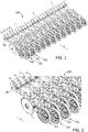
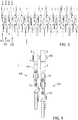
- FIGS 1 to 6 show different views of an agricultural device 100 or parts thereof according to an embodiment of the invention.
- the device 100 is described below with reference to FIG Figures 1 to 6 described.
- the device 100 comprises a support structure 10 and a plurality of row units.
- the row units are available as coulters with z. B. furrow-generating tools, seed pressure rollers (z. B. rollers), saddle lines, etc. formed.
- the device 100 comprises a first group G1 of row units, the row units of the first group G1 being connected to the support structure 10 by means of elastic connecting elements 1, in particular being mounted on the support structure 10. Furthermore, the device 100 comprises a second group G2 of row units, the row units of the second group G2 being connected to the support structure 10 by means of elastic connecting elements 2, in particular being mounted on the support structure 10.
- the row units of the first group G1 and the row units of the second group G2 are arranged alternately along the support structure 10 and are arranged offset from one another in the longitudinal direction L thereof.
- the row units of the first group G1 protrude less from the support structure 10 than the row units of the second group G2 and therefore have a shorter lever length.
- the row units of the first group G1 are preferably shorter than the row units of the second group G2.
- the support structure 10 forms a common support for the row units of the first group G1 and the second group G2.
- the offset in the longitudinal direction L is usually used to avoid blockages.
- connecting elements 1 of the first group G1 and the connecting elements 2 of the second group G2 are designed as leaf spring elements and have different elasticities (in particular different spring stiffnesses and / or spring characteristics).
- their contact forces (in particular pretensioning forces) and / or working depths can be adapted to one another, in particular substantially adapted to one another.
- the leaf spring elements 1 and the leaf spring elements 2 enable, in particular, predefinable and, in particular, mutually adaptable support forces (e.g. coulter pressures) and / or working depths, despite the offset in the longitudinal direction L.
- support forces e.g. coulter pressures
- Figure 4 shows e.g. B. that the leaf spring elements 2 of the second group G2 are longer, but also wider and thus more rigid than the leaf spring elements 1 of the first group G1.
- the leaf spring elements 1 and the leaf spring elements 2 allow an elastic swivel mounting relative to the support structure 10, so that the row units of the first group G1 and the second group G2 move upwards and then downwards when driving over an obstacle (e.g. a stone or pile of earth) can pivot what is in Figure 6 is indicated schematically by the double arrow. By pivoting upwards, a restoring force is generated at the same time.
- an obstacle e.g. a stone or pile of earth
- the embodiment shown include both the leaf spring elements 1 of the first group G1 and the leaf spring elements 2 of the second group curved subsections.
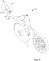
- Figure 5 shows, by way of example, a row unit of the first group G1, wherein the row units of the second group G2, with the exception of the leaf spring elements 2, can be constructed essentially identically.
- the row unit comprises a support arm body T1 for mounting the furrow-generating tool, the seed pressure roller (e.g. rollers), the seed pipe, etc.
- the seed pressure roller e.g. rollers
- the support arm body T1 with the support and assembly functions is expediently of course made more rigid than the leaf spring element 1.
- the leaf spring element 1 comprises a (z. B. substantially rectilinearly extending) first section 1.1, which can be mounted on the support structure 10.
- the leaf spring element 1 comprises a (for example, essentially rectilinearly extending) second partial section 1.2, to which the support arm body T1 is mounted by means of a fastening device (for example a screw connection).
- the leaf spring element 1 comprises a curved section 1.3, which extends between the first section 1.1 and the second section 1.2.
- the curved section 1.3 can, for. B. be curved by more than 180 °, more than 225 ° or more than 250 °, preferably by substantially 270 °.
- the leaf spring element 1 can, for. B. extend through a holding or stop element 3 therethrough.
- the holding or stop element 3 can limit the freedom of movement in particular of the second subsection 1.2 downwards and essentially in the longitudinal direction of the support structure 10 and, for example. B. also serve as an alignment aid.
- All row units and / or leaf spring elements 1 of the first group G1 are preferably designed as described above.
- all row units of the second group G2 can expediently be constructed essentially identically to the row units of the first group G1.
- the leaf spring elements 2 are in particular longer and stiffer (e.g. wider and / or thicker) than the leaf spring elements 1.
- the leaf spring elements 2 z. B overall or only in areas wider and / or thicker than the leaf spring elements 1.
- z. B the radius of curvature of the third subsection 1.3, for example, increased or decreased in order to adjust the elasticity as desired.
- Figure 7 shows a sowing and / or soil cultivating machine with a device 100.
- a seed container 101 is provided in order to supply the row units of the first group G1 and the second group G2 with seed.
- the seed container 101 can with z. B. integrated metering devices, each row unit can be assigned its own metering device.
- FIGS 8 and 9 show different views of a support arm body T1 with, in particular, a leaf spring element 1 that is integrally connected in one piece.
- leaf spring element 1 is not mounted on the support arm body T1 by means of a fastening device, but is connected in one piece and integrally with the support arm body T1.
- the leaf spring element 1 and the support arm body T1 are expediently made of fiber-reinforced plastic.
- the main area of the support arm body T1 with the support and assembly function for, in particular, the furrow-producing tool and / or the seed pressure roller and / or the seed line is of course expediently designed to be more rigid than the leaf spring element 1, in particular to be essentially rigid.
- the support arm bodies T2 can be designed similarly to the support arm body T1 described above, that is to say in particular with leaf spring elements 2, which are integrally connected in one piece in the longitudinal direction L longer than the support arm body T1.
- the leaf spring elements 2 used for the second group G2 can, however, expediently be made more rigid than the leaf spring elements 1 of the first group G1.
- leaf spring elements 1 and 2 shown preferably form bearing elements for expedient direct or indirect mounting on the support structure 10, in particular for the formation of elastic pivot mountings.
Landscapes
- Life Sciences & Earth Sciences (AREA)
- Soil Sciences (AREA)
- Environmental Sciences (AREA)
- Engineering & Computer Science (AREA)
- Mechanical Engineering (AREA)
- Pretreatment Of Seeds And Plants (AREA)
- Tires In General (AREA)
- Soil Working Implements (AREA)
Applications Claiming Priority (1)
| Application Number | Priority Date | Filing Date | Title |
|---|---|---|---|
| DE102020104451.8A DE102020104451A1 (de) | 2020-02-20 | 2020-02-20 | Landwirtschaftliche Vorrichtung mit unterschiedlich elastischen Lagerelementen |
Publications (2)
| Publication Number | Publication Date |
|---|---|
| EP3868191A1 true EP3868191A1 (fr) | 2021-08-25 |
| EP3868191B1 EP3868191B1 (fr) | 2022-06-01 |
Family
ID=74550554
Family Applications (1)
| Application Number | Title | Priority Date | Filing Date |
|---|---|---|---|
| EP21155029.8A Active EP3868191B1 (fr) | 2020-02-20 | 2021-02-03 | Dispositif agricole pourvu d éléments paliers élastiques différents |
Country Status (2)
| Country | Link |
|---|---|
| EP (1) | EP3868191B1 (fr) |
| DE (1) | DE102020104451A1 (fr) |
Cited By (2)
| Publication number | Priority date | Publication date | Assignee | Title |
|---|---|---|---|---|
| DE102023103179A1 (de) | 2023-02-09 | 2024-08-14 | Horsch Maschinen Gmbh | Tragvorrichtung zur montage an einen maschinenrahmen einer landwirtschaftlichen arbeitsmaschine, landwirtschaftliche arbeitsmaschine mit einer solchen tragvorrichtung und verfahren zur verstellung zumindest einer werkzeugeinrichtung einer landwirtschaftlichen arbeitsmaschine |
| EP4706355A1 (fr) | 2024-08-13 | 2026-03-11 | Lemken GmbH & Co KG | Dispositif de travail du sol agricole |
Citations (4)
| Publication number | Priority date | Publication date | Assignee | Title |
|---|---|---|---|---|
| DE8901351U1 (de) * | 1989-02-07 | 1989-03-23 | A. J. Tröster GmbH & Co KG, 6308 Butzbach | Insbesondere für eine Drillmaschine bestimmte Zustreicheinrichtung |
| DE9102567U1 (de) * | 1990-03-02 | 1991-05-23 | Sulky-Burel S.A., Chateaubourg | Spurziehvorrichtung für eine Landmaschine |
| DE102009058342A1 (de) | 2009-12-15 | 2011-06-16 | Alois Pöttinger Maschinenfabrik Gmbh | Aufhängungsvorrichtung |
| DE102010017013B3 (de) * | 2010-05-18 | 2012-04-19 | Willi Auf der Landwehr | Blattfederelement für Bodenbearbeitungsmaschinen |
Family Cites Families (1)
| Publication number | Priority date | Publication date | Assignee | Title |
|---|---|---|---|---|
| DE102014111099A1 (de) | 2014-08-05 | 2016-02-11 | Amazonen-Werke H. Dreyer Gmbh & Co. Kg | Sämaschine |
-
2020
- 2020-02-20 DE DE102020104451.8A patent/DE102020104451A1/de not_active Withdrawn
-
2021
- 2021-02-03 EP EP21155029.8A patent/EP3868191B1/fr active Active
Patent Citations (4)
| Publication number | Priority date | Publication date | Assignee | Title |
|---|---|---|---|---|
| DE8901351U1 (de) * | 1989-02-07 | 1989-03-23 | A. J. Tröster GmbH & Co KG, 6308 Butzbach | Insbesondere für eine Drillmaschine bestimmte Zustreicheinrichtung |
| DE9102567U1 (de) * | 1990-03-02 | 1991-05-23 | Sulky-Burel S.A., Chateaubourg | Spurziehvorrichtung für eine Landmaschine |
| DE102009058342A1 (de) | 2009-12-15 | 2011-06-16 | Alois Pöttinger Maschinenfabrik Gmbh | Aufhängungsvorrichtung |
| DE102010017013B3 (de) * | 2010-05-18 | 2012-04-19 | Willi Auf der Landwehr | Blattfederelement für Bodenbearbeitungsmaschinen |
Cited By (3)
| Publication number | Priority date | Publication date | Assignee | Title |
|---|---|---|---|---|
| DE102023103179A1 (de) | 2023-02-09 | 2024-08-14 | Horsch Maschinen Gmbh | Tragvorrichtung zur montage an einen maschinenrahmen einer landwirtschaftlichen arbeitsmaschine, landwirtschaftliche arbeitsmaschine mit einer solchen tragvorrichtung und verfahren zur verstellung zumindest einer werkzeugeinrichtung einer landwirtschaftlichen arbeitsmaschine |
| EP4424128A1 (fr) | 2023-02-09 | 2024-09-04 | Horsch Maschinen GmbH | Dispositif de support destiné à être monté sur un châssis de machine d'une machine de travail agricole, machine de travail agricole dotée d'un tel dispositif de support et procédé de réglage d'au moins un dispositif de machine de travail agricole |
| EP4706355A1 (fr) | 2024-08-13 | 2026-03-11 | Lemken GmbH & Co KG | Dispositif de travail du sol agricole |
Also Published As
| Publication number | Publication date |
|---|---|
| DE102020104451A1 (de) | 2021-08-26 |
| EP3868191B1 (fr) | 2022-06-01 |
Similar Documents
| Publication | Publication Date | Title |
|---|---|---|
| EP0140190A2 (fr) | Semoir | |
| EP2912933B1 (fr) | Machine agricole de traitement du sol | |
| DE102007028193A1 (de) | Sämaschine | |
| DE102008045635A1 (de) | Landmaschine | |
| EP3868191B1 (fr) | Dispositif agricole pourvu d éléments paliers élastiques différents | |
| EP1391147B1 (fr) | Soc d'ensemencement avec des socs de semoir échelonnés suivis de rouleaux de pression | |
| EP2374343B1 (fr) | Agrégat de semoir monograine | |
| EP1964459A1 (fr) | Machine à semer | |
| DE102020104456A1 (de) | Landwirtschaftlicher Tragarmkorpus | |
| DE202019100926U1 (de) | Vorrichtung für eine landwirtschaftliche Maschine | |
| EP1060649A2 (fr) | Semoir entraíné par un tracteur avec soc semeur et attelage trois points | |
| EP0445582B1 (fr) | Machine pour travailler le sol | |
| DE60132749T2 (de) | Sämaschine | |
| DE102017128612A1 (de) | Landwirtschaftliche Bodenbearbeitungsvorrichtung | |
| DE602004004342T2 (de) | Sämaschine mit einer Einstellvorrichtung | |
| DE102004008089A1 (de) | Sävorrichtung, insbesondere für Mulchsaat | |
| DE102020104452A1 (de) | Federelement für eine Sä- und/oder Bodenbearbeitungsmaschine | |
| DE102022119611A1 (de) | Scharvorrichtung und landwirtschaftliche arbeitsmaschine mit einer mehrzahl derartiger scharvorrichtungen | |
| DE202010005461U1 (de) | Blattfederelement für Bodenbearbeitungsmaschinen | |
| EP3698617B1 (fr) | Système de soc de semis pour une machine agricole | |
| DE202004020159U1 (de) | Scheibenegge | |
| DE4138154C1 (en) | Fertiliser placing ground share - has curved cutting edge and includes pivot joint and yielding part | |
| WO2021047967A1 (fr) | Dispositif de semis | |
| DE102020111545A1 (de) | Landwirtschaftliche Bodenbearbeitungsmaschine mit Aushubvorrichtung | |
| DE102010017013B3 (de) | Blattfederelement für Bodenbearbeitungsmaschinen |
Legal Events
| Date | Code | Title | Description |
|---|---|---|---|
| PUAI | Public reference made under article 153(3) epc to a published international application that has entered the european phase |
Free format text: ORIGINAL CODE: 0009012 |
|
| STAA | Information on the status of an ep patent application or granted ep patent |
Free format text: STATUS: THE APPLICATION HAS BEEN PUBLISHED |
|
| AK | Designated contracting states |
Kind code of ref document: A1 Designated state(s): AL AT BE BG CH CY CZ DE DK EE ES FI FR GB GR HR HU IE IS IT LI LT LU LV MC MK MT NL NO PL PT RO RS SE SI SK SM TR |
|
| STAA | Information on the status of an ep patent application or granted ep patent |
Free format text: STATUS: REQUEST FOR EXAMINATION WAS MADE |
|
| 17P | Request for examination filed |
Effective date: 20210820 |
|
| RBV | Designated contracting states (corrected) |
Designated state(s): AL AT BE BG CH CY CZ DE DK EE ES FI FR GB GR HR HU IE IS IT LI LT LU LV MC MK MT NL NO PL PT RO RS SE SI SK SM TR |
|
| GRAP | Despatch of communication of intention to grant a patent |
Free format text: ORIGINAL CODE: EPIDOSNIGR1 |
|
| STAA | Information on the status of an ep patent application or granted ep patent |
Free format text: STATUS: GRANT OF PATENT IS INTENDED |
|
| RIC1 | Information provided on ipc code assigned before grant |
Ipc: A01C 7/20 20060101ALI20211214BHEP Ipc: A01B 61/04 20060101AFI20211214BHEP |
|
| INTG | Intention to grant announced |
Effective date: 20220107 |
|
| GRAS | Grant fee paid |
Free format text: ORIGINAL CODE: EPIDOSNIGR3 |
|
| GRAA | (expected) grant |
Free format text: ORIGINAL CODE: 0009210 |
|
| STAA | Information on the status of an ep patent application or granted ep patent |
Free format text: STATUS: THE PATENT HAS BEEN GRANTED |
|
| AK | Designated contracting states |
Kind code of ref document: B1 Designated state(s): AL AT BE BG CH CY CZ DE DK EE ES FI FR GB GR HR HU IE IS IT LI LT LU LV MC MK MT NL NO PL PT RO RS SE SI SK SM TR |
|
| REG | Reference to a national code |
Ref country code: GB Ref legal event code: FG4D Free format text: NOT ENGLISH |
|
| REG | Reference to a national code |
Ref country code: AT Ref legal event code: REF Ref document number: 1494780 Country of ref document: AT Kind code of ref document: T Effective date: 20220615 Ref country code: CH Ref legal event code: EP |
|
| REG | Reference to a national code |
Ref country code: IE Ref legal event code: FG4D Free format text: LANGUAGE OF EP DOCUMENT: GERMAN |
|
| REG | Reference to a national code |
Ref country code: DE Ref legal event code: R096 Ref document number: 502021000037 Country of ref document: DE |
|
| REG | Reference to a national code |
Ref country code: LT Ref legal event code: MG9D |
|
| REG | Reference to a national code |
Ref country code: NL Ref legal event code: MP Effective date: 20220601 |
|
| PG25 | Lapsed in a contracting state [announced via postgrant information from national office to epo] |
Ref country code: SE Free format text: LAPSE BECAUSE OF FAILURE TO SUBMIT A TRANSLATION OF THE DESCRIPTION OR TO PAY THE FEE WITHIN THE PRESCRIBED TIME-LIMIT Effective date: 20220601 Ref country code: NO Free format text: LAPSE BECAUSE OF FAILURE TO SUBMIT A TRANSLATION OF THE DESCRIPTION OR TO PAY THE FEE WITHIN THE PRESCRIBED TIME-LIMIT Effective date: 20220901 Ref country code: LT Free format text: LAPSE BECAUSE OF FAILURE TO SUBMIT A TRANSLATION OF THE DESCRIPTION OR TO PAY THE FEE WITHIN THE PRESCRIBED TIME-LIMIT Effective date: 20220601 Ref country code: HR Free format text: LAPSE BECAUSE OF FAILURE TO SUBMIT A TRANSLATION OF THE DESCRIPTION OR TO PAY THE FEE WITHIN THE PRESCRIBED TIME-LIMIT Effective date: 20220601 Ref country code: GR Free format text: LAPSE BECAUSE OF FAILURE TO SUBMIT A TRANSLATION OF THE DESCRIPTION OR TO PAY THE FEE WITHIN THE PRESCRIBED TIME-LIMIT Effective date: 20220902 Ref country code: FI Free format text: LAPSE BECAUSE OF FAILURE TO SUBMIT A TRANSLATION OF THE DESCRIPTION OR TO PAY THE FEE WITHIN THE PRESCRIBED TIME-LIMIT Effective date: 20220601 Ref country code: BG Free format text: LAPSE BECAUSE OF FAILURE TO SUBMIT A TRANSLATION OF THE DESCRIPTION OR TO PAY THE FEE WITHIN THE PRESCRIBED TIME-LIMIT Effective date: 20220901 |
|
| PG25 | Lapsed in a contracting state [announced via postgrant information from national office to epo] |
Ref country code: RS Free format text: LAPSE BECAUSE OF FAILURE TO SUBMIT A TRANSLATION OF THE DESCRIPTION OR TO PAY THE FEE WITHIN THE PRESCRIBED TIME-LIMIT Effective date: 20220601 Ref country code: PL Free format text: LAPSE BECAUSE OF FAILURE TO SUBMIT A TRANSLATION OF THE DESCRIPTION OR TO PAY THE FEE WITHIN THE PRESCRIBED TIME-LIMIT Effective date: 20220601 Ref country code: LV Free format text: LAPSE BECAUSE OF FAILURE TO SUBMIT A TRANSLATION OF THE DESCRIPTION OR TO PAY THE FEE WITHIN THE PRESCRIBED TIME-LIMIT Effective date: 20220601 |
|
| PG25 | Lapsed in a contracting state [announced via postgrant information from national office to epo] |
Ref country code: NL Free format text: LAPSE BECAUSE OF FAILURE TO SUBMIT A TRANSLATION OF THE DESCRIPTION OR TO PAY THE FEE WITHIN THE PRESCRIBED TIME-LIMIT Effective date: 20220601 |
|
| PG25 | Lapsed in a contracting state [announced via postgrant information from national office to epo] |
Ref country code: SM Free format text: LAPSE BECAUSE OF FAILURE TO SUBMIT A TRANSLATION OF THE DESCRIPTION OR TO PAY THE FEE WITHIN THE PRESCRIBED TIME-LIMIT Effective date: 20220601 Ref country code: SK Free format text: LAPSE BECAUSE OF FAILURE TO SUBMIT A TRANSLATION OF THE DESCRIPTION OR TO PAY THE FEE WITHIN THE PRESCRIBED TIME-LIMIT Effective date: 20220601 Ref country code: RO Free format text: LAPSE BECAUSE OF FAILURE TO SUBMIT A TRANSLATION OF THE DESCRIPTION OR TO PAY THE FEE WITHIN THE PRESCRIBED TIME-LIMIT Effective date: 20220601 Ref country code: PT Free format text: LAPSE BECAUSE OF FAILURE TO SUBMIT A TRANSLATION OF THE DESCRIPTION OR TO PAY THE FEE WITHIN THE PRESCRIBED TIME-LIMIT Effective date: 20221003 Ref country code: ES Free format text: LAPSE BECAUSE OF FAILURE TO SUBMIT A TRANSLATION OF THE DESCRIPTION OR TO PAY THE FEE WITHIN THE PRESCRIBED TIME-LIMIT Effective date: 20220601 Ref country code: EE Free format text: LAPSE BECAUSE OF FAILURE TO SUBMIT A TRANSLATION OF THE DESCRIPTION OR TO PAY THE FEE WITHIN THE PRESCRIBED TIME-LIMIT Effective date: 20220601 |
|
| PG25 | Lapsed in a contracting state [announced via postgrant information from national office to epo] |
Ref country code: IS Free format text: LAPSE BECAUSE OF FAILURE TO SUBMIT A TRANSLATION OF THE DESCRIPTION OR TO PAY THE FEE WITHIN THE PRESCRIBED TIME-LIMIT Effective date: 20221001 |
|
| REG | Reference to a national code |
Ref country code: DE Ref legal event code: R097 Ref document number: 502021000037 Country of ref document: DE |
|
| PG25 | Lapsed in a contracting state [announced via postgrant information from national office to epo] |
Ref country code: AL Free format text: LAPSE BECAUSE OF FAILURE TO SUBMIT A TRANSLATION OF THE DESCRIPTION OR TO PAY THE FEE WITHIN THE PRESCRIBED TIME-LIMIT Effective date: 20220601 |
|
| PLBE | No opposition filed within time limit |
Free format text: ORIGINAL CODE: 0009261 |
|
| STAA | Information on the status of an ep patent application or granted ep patent |
Free format text: STATUS: NO OPPOSITION FILED WITHIN TIME LIMIT |
|
| PG25 | Lapsed in a contracting state [announced via postgrant information from national office to epo] |
Ref country code: DK Free format text: LAPSE BECAUSE OF FAILURE TO SUBMIT A TRANSLATION OF THE DESCRIPTION OR TO PAY THE FEE WITHIN THE PRESCRIBED TIME-LIMIT Effective date: 20220601 |
|
| 26N | No opposition filed |
Effective date: 20230302 |
|
| PG25 | Lapsed in a contracting state [announced via postgrant information from national office to epo] |
Ref country code: MC Free format text: LAPSE BECAUSE OF FAILURE TO SUBMIT A TRANSLATION OF THE DESCRIPTION OR TO PAY THE FEE WITHIN THE PRESCRIBED TIME-LIMIT Effective date: 20220601 |
|
| REG | Reference to a national code |
Ref country code: BE Ref legal event code: MM Effective date: 20230228 |
|
| PG25 | Lapsed in a contracting state [announced via postgrant information from national office to epo] |
Ref country code: LU Free format text: LAPSE BECAUSE OF NON-PAYMENT OF DUE FEES Effective date: 20230203 |
|
| REG | Reference to a national code |
Ref country code: IE Ref legal event code: MM4A |
|
| PG25 | Lapsed in a contracting state [announced via postgrant information from national office to epo] |
Ref country code: IT Free format text: LAPSE BECAUSE OF FAILURE TO SUBMIT A TRANSLATION OF THE DESCRIPTION OR TO PAY THE FEE WITHIN THE PRESCRIBED TIME-LIMIT Effective date: 20220601 Ref country code: IE Free format text: LAPSE BECAUSE OF NON-PAYMENT OF DUE FEES Effective date: 20230203 Ref country code: FR Free format text: LAPSE BECAUSE OF NON-PAYMENT OF DUE FEES Effective date: 20230228 |
|
| PG25 | Lapsed in a contracting state [announced via postgrant information from national office to epo] |
Ref country code: BE Free format text: LAPSE BECAUSE OF NON-PAYMENT OF DUE FEES Effective date: 20230228 |
|
| REG | Reference to a national code |
Ref country code: CH Ref legal event code: PL |
|
| PG25 | Lapsed in a contracting state [announced via postgrant information from national office to epo] |
Ref country code: CH Free format text: LAPSE BECAUSE OF NON-PAYMENT OF DUE FEES Effective date: 20240229 |
|
| PG25 | Lapsed in a contracting state [announced via postgrant information from national office to epo] |
Ref country code: CH Free format text: LAPSE BECAUSE OF NON-PAYMENT OF DUE FEES Effective date: 20240229 |
|
| PG25 | Lapsed in a contracting state [announced via postgrant information from national office to epo] |
Ref country code: BG Free format text: LAPSE BECAUSE OF FAILURE TO SUBMIT A TRANSLATION OF THE DESCRIPTION OR TO PAY THE FEE WITHIN THE PRESCRIBED TIME-LIMIT Effective date: 20220601 |
|
| PG25 | Lapsed in a contracting state [announced via postgrant information from national office to epo] |
Ref country code: BG Free format text: LAPSE BECAUSE OF FAILURE TO SUBMIT A TRANSLATION OF THE DESCRIPTION OR TO PAY THE FEE WITHIN THE PRESCRIBED TIME-LIMIT Effective date: 20220601 |
|
| PGFP | Annual fee paid to national office [announced via postgrant information from national office to epo] |
Ref country code: AT Payment date: 20250417 Year of fee payment: 5 |
|
| PG25 | Lapsed in a contracting state [announced via postgrant information from national office to epo] |
Ref country code: CY Free format text: LAPSE BECAUSE OF FAILURE TO SUBMIT A TRANSLATION OF THE DESCRIPTION OR TO PAY THE FEE WITHIN THE PRESCRIBED TIME-LIMIT; INVALID AB INITIO Effective date: 20210203 |
|
| PG25 | Lapsed in a contracting state [announced via postgrant information from national office to epo] |
Ref country code: HU Free format text: LAPSE BECAUSE OF FAILURE TO SUBMIT A TRANSLATION OF THE DESCRIPTION OR TO PAY THE FEE WITHIN THE PRESCRIBED TIME-LIMIT; INVALID AB INITIO Effective date: 20210203 |
|
| GBPC | Gb: european patent ceased through non-payment of renewal fee |
Effective date: 20250203 |
|
| PG25 | Lapsed in a contracting state [announced via postgrant information from national office to epo] |
Ref country code: TR Free format text: LAPSE BECAUSE OF FAILURE TO SUBMIT A TRANSLATION OF THE DESCRIPTION OR TO PAY THE FEE WITHIN THE PRESCRIBED TIME-LIMIT Effective date: 20220601 |
|
| PG25 | Lapsed in a contracting state [announced via postgrant information from national office to epo] |
Ref country code: GB Free format text: LAPSE BECAUSE OF NON-PAYMENT OF DUE FEES Effective date: 20250203 |
|
| PG25 | Lapsed in a contracting state [announced via postgrant information from national office to epo] |
Ref country code: SI Free format text: LAPSE BECAUSE OF FAILURE TO SUBMIT A TRANSLATION OF THE DESCRIPTION OR TO PAY THE FEE WITHIN THE PRESCRIBED TIME-LIMIT Effective date: 20220601 |
|
| PGFP | Annual fee paid to national office [announced via postgrant information from national office to epo] |
Ref country code: DE Payment date: 20260217 Year of fee payment: 6 |
|
| PGFP | Annual fee paid to national office [announced via postgrant information from national office to epo] |
Ref country code: CZ Payment date: 20260121 Year of fee payment: 6 |