EP4424128A1 - Dispositif de support destiné à être monté sur un châssis de machine d'une machine de travail agricole, machine de travail agricole dotée d'un tel dispositif de support et procédé de réglage d'au moins un dispositif de machine de travail agricole - Google Patents
Dispositif de support destiné à être monté sur un châssis de machine d'une machine de travail agricole, machine de travail agricole dotée d'un tel dispositif de support et procédé de réglage d'au moins un dispositif de machine de travail agricole Download PDFInfo
- Publication number
- EP4424128A1 EP4424128A1 EP24155297.5A EP24155297A EP4424128A1 EP 4424128 A1 EP4424128 A1 EP 4424128A1 EP 24155297 A EP24155297 A EP 24155297A EP 4424128 A1 EP4424128 A1 EP 4424128A1
- Authority
- EP
- European Patent Office
- Prior art keywords
- tool
- unit
- coupling unit
- actuation
- support
- Prior art date
- Legal status (The legal status is an assumption and is not a legal conclusion. Google has not performed a legal analysis and makes no representation as to the accuracy of the status listed.)
- Pending
Links
Images




Classifications
-
- A—HUMAN NECESSITIES
- A01—AGRICULTURE; FORESTRY; ANIMAL HUSBANDRY; HUNTING; TRAPPING; FISHING
- A01B—SOIL WORKING IN AGRICULTURE OR FORESTRY; PARTS, DETAILS, OR ACCESSORIES OF AGRICULTURAL MACHINES OR IMPLEMENTS, IN GENERAL
- A01B15/00—Elements, tools, or details of ploughs
- A01B15/14—Frames
- A01B15/145—Frames the plough blades being connected to the plough beam for unisono adjustment of the furrow width
-
- A—HUMAN NECESSITIES
- A01—AGRICULTURE; FORESTRY; ANIMAL HUSBANDRY; HUNTING; TRAPPING; FISHING
- A01C—PLANTING; SOWING; FERTILISING
- A01C7/00—Sowing
- A01C7/20—Parts of seeders for conducting and depositing seed
- A01C7/201—Mounting of the seeding tools
- A01C7/203—Mounting of the seeding tools comprising depth regulation means
-
- A—HUMAN NECESSITIES
- A01—AGRICULTURE; FORESTRY; ANIMAL HUSBANDRY; HUNTING; TRAPPING; FISHING
- A01C—PLANTING; SOWING; FERTILISING
- A01C7/00—Sowing
- A01C7/20—Parts of seeders for conducting and depositing seed
- A01C7/201—Mounting of the seeding tools
- A01C7/205—Mounting of the seeding tools comprising pressure regulation means
-
- A—HUMAN NECESSITIES
- A01—AGRICULTURE; FORESTRY; ANIMAL HUSBANDRY; HUNTING; TRAPPING; FISHING
- A01C—PLANTING; SOWING; FERTILISING
- A01C7/00—Sowing
- A01C7/20—Parts of seeders for conducting and depositing seed
- A01C7/208—Chassis; Coupling means to a tractor or the like; Lifting means; Side markers
Definitions
- the present invention is in the field of agricultural technology and relates to a support device for mounting on a machine frame of an agricultural working machine, an agricultural working machine with such a support device and a method for adjusting at least one tool device of such an agricultural working machine.
- Agricultural machines for working the soil and/or for introducing agricultural crops into the soil are equipped with seed coulter units, for example, and are usually mounted on a support of an agricultural machine, such as a seed drill, via a swing arm or a so-called parallelogram guide.
- a so-called rubber cord or a leaf spring is often used to mount the seed coulter unit.
- the coulter unit In the case of coulter units which are each supported by a swing arm, the coulter unit is adjusted to achieve a desired working depth by adjusting the swing arm support, i.e. by swiveling and/or adjusting the height of the support. Such an adjustment is usually carried out using a hydraulic cylinder. As soon as the coulter unit has to be adjusted to achieve a different desired working depth, it is sufficient to limit the stroke of the hydraulic cylinder using so-called aluminum clips.
- a so-called coulter pressure can be set on the sowing coulter units.
- the coulter pressure is preferably the force by means of which the sowing coulter unit is guided along the ground.
- the coulter pressure is usually also adjusted using a hydraulic cylinder, whereby in addition to an adjustment to achieve a desired working depth, the coulter pressure must also be adjusted, since the working depth and the coulter pressure are related to one another.
- the coulter pressure is also usually adjusted by pivoting and/or adjusting the height of the support of the respective frame of the sowing coulter unit.
- the present invention relates to a support device for mounting on a machine frame, preferably on a main support frame, of an agricultural work machine, with at least one tool device which, preferably in an operating state of the agricultural work machine along a direction of movement, is configured for working a soil and/or for introducing an agricultural product into a soil, with at least one adjusting device which, preferably in an assembled state of the support device, is configured for adjusting the at least one tool device, wherein the at least one adjusting device comprises a coupling unit which is configured for mounting, preferably pivotable mounting, on the machine frame and for actuation by at least one actuator device, and wherein the adjusting device comprises an actuating unit which is configured for adjusting a position of the at least one tool device in relation to the soil and/or to the machine frame, wherein the coupling unit and the actuating unit are movably coupled to one another and are configured, preferably in an operating state of the agricultural work machine, to convert an actuation of the coupling unit and/or
- the present invention makes it possible to provide a carrying device and, furthermore, an agricultural work machine with such a carrying device, in which, above all, adjustment of the working depth of the at least one tool device is significantly simplified and, in particular, a number of steps or measures required for adjustment of the at least one tool device is significantly reduced.
- a defined tool state of the at least one tool device can be set automatically by means of the at least one adjustment device. Necessary manual adjustment work on the at least one tool device is eliminated or at least significantly reduced. This is advantageous, for example, when the at least one tool device comprises two tool units, of which one tool unit is a cutting disk unit, i.e. a share unit, and the other tool unit is a roller unit for pressing the ground, i.e. a pressure roller.
- the at least one adjustment device preferably represents an adjustment mechanism for at least one tool device which is arranged or mounted on the support device By means of the at least one adjustment device, a specific or desired adjustment of the at least one tool device can thus be achieved.
- the actuating unit is configured to set a defined tool position of the at least one tool device to the ground and/or a defined tool pressure of the at least one tool device to the ground, each substantially simultaneously with the actuation of the coupling unit.
- a defined working depth of the at least one tool device in the ground and/or a defined alignment of the at least one tool device to the ground, i.e. to the ground surface is set directly, for example when the coupling unit is actuated.
- This can be implemented additionally or alternatively for setting the defined tool pressure of the at least one tool device on the ground.
- the first tool unit is configured as a cutting disk unit, i.e. as a blade unit, a defined blade pressure of the at least one tool device on the ground can thus be set additionally or alternatively.
- the support device comprises a reconsolidation device which is configured to press the ground, wherein the reconsolidation device is attached to the coupling unit in order to set a defined reconsolidation device position of the reconsolidation device relative to the ground when the coupling unit is actuated substantially simultaneously with the defined adjustment of the at least one tool device, and/or that the actuating unit and the reconsolidation device are each coupled to the coupling unit on opposite sides and are configured to move the reconsolidation device in the direction of the machine frame and substantially simultaneously move the at least one tool device in the direction of the ground when the coupling unit is actuated.
- the at least one adjusting device and the at least one tool device comprise or form an adjustable coupling mechanism, preferably an adjustable multi-joint mechanism or an adjustable parallelogram mechanism, which comprises at least four articulation points, wherein two first articulation points, preferably on the at least one tool device, are arranged at a distance from one another which is substantially constant; and/or wherein two second articulation points, preferably on the at least one adjusting device, are arranged at a distance from one another which is variable depending on the actuation of the coupling unit.
- an adjustable coupling mechanism preferably an adjustable multi-joint mechanism or an adjustable parallelogram mechanism, which comprises at least four articulation points, wherein two first articulation points, preferably on the at least one tool device, are arranged at a distance from one another which is substantially constant; and/or wherein two second articulation points, preferably on the at least one adjusting device, are arranged at a distance from one another which is variable depending on the actuation of the coupling unit.
- a so-called parallelogram coulter unit with a combined pressure roller unit can be provided as at least one tool device.
- this makes it possible to adjust the parallelogram coulter unit essentially or almost identically to a coulter unit mounted with only one rocker.
- the coupling unit is configured for pivotable mounting, preferably by means of a bolt, on the machine frame, and/or that the actuating unit is pivotably mounted, preferably by means of a bolt, on the coupling unit, wherein preferably a resulting pivot axis of the coupling unit and a resulting pivot axis of the actuating unit are arranged substantially parallel to one another and/or at a substantially constant distance from one another.
- the at least one adjustment device is characterized by its relatively simple and compact design, i.e. it saves space.
- the actuating unit comprises at least one pivotably mounted support element, which is configured for pivotally mounting on the machine frame, wherein preferably a length of the at least one support element is variably adjustable in order to convert the actuation of the coupling unit in a defined ratio or according to a defined function geometrically linear or non-linear.
- manufacturing tolerances can also be compensated for, for example, by means of a variably adjustable support element.
- the movement of the actuating unit can be related to the movement of the coupling unit in a linear, i.e. constant, relationship or in a non-linear relationship.
- a pivoting movement of the coupling unit by a certain value can be achieved in a pivoting movement of the actuating unit by this certain value multiplied by a factor.
- the actuation of the coupling unit comprises moving the coupling unit in the form of pivoting.
- a conversion of the actuation of the coupling unit comprises moving the actuating unit in the form of pivoting depending on the defined ratio or the defined function.
- the at least one tool device can be mounted on the coupling unit via at least one damping element, wherein the at least one adjusting device comprises a pre-tensioning unit which is configured to apply an adjustable pre-tensioning force to the at least one damping element.
- the at least one damping element can in particular be a spring element.
- the coupling unit preferably a free end of the coupling unit, comprises at least one receiving section for the at least one actuator device, which is configured for pivotably mounting the at least one actuator device on or opposite the coupling unit, wherein the at least one receiving section is preferably configured in a substantially fork-shaped manner at least in sections in a side view, preferably in the direction of a resulting pivot axis of the actuator device.
- the at least one tool device is configured as a separate, preferably self-sufficient (pre-)assemblable, tool device which comprises a tool carrier to form individually configurable tool units, wherein the tool carrier is preferably connected in an articulated manner to the actuating unit via an actuating element, and/or wherein the tool carrier is preferably mounted on a rotatable cross member element of the coupling unit via a pivoting element and at least one damping element.
- the at least one tool device comprises a first tool unit and a second tool unit, wherein the first tool unit and/or the second tool unit are arranged on a tool carrier of the at least one tool device, at least in one direction of movement of the work machine, at a distance from one another or variably adjustable from one another, wherein the tool carrier is configured such that when the coupling unit is actuated, a defined tool position of the second tool unit is set to the ground and/or that a defined tool pressure of the first tool unit is set to the ground or vice versa.
- the at least one tool device can comprise at least one tool unit of the following tool units: a cutting disc unit for forming and/or opening a furrow in the ground, wherein the cutting disc unit preferably comprises two cutting discs arranged at an angle to one another; a skid unit for forming and/or opening a furrow in the ground; a roller unit for at least partially pressing the ground, preferably a furrow, and/or at least partially closing it, and/or for catching and/or braking an agricultural product in the ground, preferably in the region of a furrow; and/or a sowing unit with at least one guide element for introducing an agricultural product into the ground, preferably depositing it in a furrow.
- a cutting disc unit for forming and/or opening a furrow in the ground, wherein the cutting disc unit preferably comprises two cutting discs arranged at an angle to one another
- a skid unit for forming and/or opening a furrow in the ground
- a roller unit for at least partially pressing the ground, preferably
- the sowing unit can comprise at least one line element for supplying the agricultural product in the form of seed and/or fertilizer.
- the at least one line element of the sowing unit can serve as a seed pipe.
- the present invention relates to an agricultural working machine, preferably for working a soil and/or for introducing an agricultural product into a soil and/or for transporting an agricultural product, with a machine frame which has a pulling and/or mounting device on a front side, via which the working machine can be pulled in a direction of movement in a transport state and in an operating state, wherein at least one support device as disclosed herein and at least one actuator device for actuating a coupling unit of the at least one support device are mounted on the machine frame, preferably on a rear side of the machine frame.
- a reconsolidation device in the transport state serves as a chassis of the work machine, preferably as a main chassis of the work machine, wherein the reconsolidation device is preferably configured as a tire packer roller.
- the reconsolidation device is preferably configured as a tire packer roller.
- other configurations of the reconsolidation device are also possible.
- the work machine is designed as a so-called attachment machine and can be mounted to a towing vehicle by means of a mounting device in the form of a three-point hitch.
- the at least one actuator device is configured as a linear actuator or comprises a linear actuator which is configured to be actuated electrically, electromechanically, pneumatically or hydraulically, and/or that the at least one actuator device is configured to adjust the actuation of the coupling unit by means of at least one stop element.
- the at least one stop element can be configured as a clamp or as a clamping element.
- the present invention relates to a method for adjusting at least one tool device of an agricultural work machine, preferably as disclosed herein, wherein the coupling unit is actuated by the at least one actuator device and the actuation of the coupling unit is converted by the coupling unit and by the actuating unit and the at least one tool device is adjusted in a defined manner depending on the converted actuation.
- At least one sensor unit detects an adjustment of a tool position of the at least one tool device to the ground and/or to the machine frame, and/or a tool pressure of the at least one tool device on the ground, preferably at least while the coupling unit is actuated, and/or that the at least one sensor unit detects forces acting on the at least one tool device and/or a working depth of the at least one tool device, preferably at least while the coupling unit is actuated, and the detected tool position and/or the detected tool pressure and/or the detected forces and/or the detected working depth are transmitted to a control device for regulating and/or controlling the at least one actuator device in order to adjust the at least one tool device in a defined manner.
- the at least one sensor unit can be connected to the Supporting device, for example on the supporting frame or on the machine frame of the agricultural working machine.
- Figure 1 shows in a first perspective view a part of an agricultural working machine 20 and a carrying device 10 according to a first embodiment of the present invention in a first operating state.
- An operating state is preferably a state of the work machine 20 in which the work machine 20 can be operated as intended and/or properly, especially to ensure functionality and safety.
- the agricultural working machine 20 is in its entirety, i.e. with the mounted carrying device 10 in Figure 6 in a third perspective view.
- the agricultural working machine 20 is preferably used for working a soil B and/or for introducing an agricultural product into a soil B and/or for transporting an agricultural product.
- the agricultural working machine 20 is in Hereinafter also abbreviated as "working machine” and based on the representation in Figure 6 described.
- Figure 1 shows a part of a machine frame 21 of the working machine 20, which can be designed, for example, in the form of a ladder frame as the main support frame of the working machine 20.
- the support device 10 is movably mounted on the machine frame 21 and is also mounted so as to be operable by means of an actuator device 22 relative to the machine frame 21 and further relative to the floor B in order to change a location, i.e. a position and an alignment of the support device 10 relative to the floor B and/or to the machine frame 21, which is explained in more detail below.
- the support device 10 comprises at least one tool device 100 and preferably a plurality of tool devices 100 or several tool devices 100. For reasons of clarity, two tool devices 100 are shown in the figures and one tool device 100 is identified by reference numerals. A tool device 100, preferably representative of the plurality or several tool devices 100, is explained in more detail below.
- the tool device 100 is preferably configured in an operating state of the work machine 20, preferably along a direction of movement BR, for working the soil B and/or for introducing an agricultural product into a soil B and/or for transporting an agricultural product.
- the agricultural product can be, for example, a seed, for example granular seed, and/or a fertilizer, for example mineral fertilizer in granular form.
- the support device 10 comprises at least one adjustment device 200 and preferably a plurality of adjustment devices 200 or several adjustment devices 200.
- the number of adjustment devices 200 is preferably matched or adapted to the number of tool devices 100.
- an adjustment device 200 and the units and elements assigned to it are identified by reference numerals in the figures. Other units and elements of the adjustment device 200 which are similar or identical to those described are hidden.
- the adjustment device 200 is configured to adjust the tool device 100. In other words, the adjustment device 200 is configured to change a tool state of the
- Tool device 100 is configured.
- the adjustment of the tool device 100 or the change in the tool state preferably comprises the setting of a position of the tool device 100 and thus a position of the tool device 100 and/or an alignment of the tool device 100 to the floor B and/or to the machine frame 21.
- the position of the tool device 100 can be, for example, a height of the tool device 100 relative to the floor B and thus a distance of a defined point of the tool device 100 to the floor B.
- the tool device 100 can be characterized by a defined working depth in the ground B and thus by a defined position and by a defined orientation and thus position relative to the ground B and/or the machine frame 21, as in a transport state of the work machine 20.
- An orientation of the tool device 100 can, for example, be characterized by an angle which the tool device 100 assumes with respect to the floor B and/or with respect to the machine frame 21.
- a transport state is preferably a state of the agricultural work machine 20 in which the agricultural work machine 20 can be moved as intended and/or properly, in particular to ensure the transport of the agricultural work machine 20, preferably on public roads and/or paths, wherein in particular legal requirements regarding the weight and dimensions of the agricultural work machine 20 are observed.
- the adjustment of the tool device 100 or the change of the tool state comprises an adjustment of a tool pressure of the tool device 100 on the ground B.
- a force is applied to the tool device 100 and transmitted via the tool device 100 to the ground B in order to realize a tool pressure on the ground B and to enable machining of the ground B.
- the adjustment device 200 comprises a coupling unit 210 and an actuating unit 220.
- the coupling unit 210 and the actuating unit 220 are preferably mechanical units or mechanical mechanisms for converting and/or transmitting movements and/or forces and/or torques in a defined ratio and/or according to a defined Function.
- the coupling unit 210 and the actuating unit 220 are kinematic systems, preferably kinematically interacting subsystems, for converting and/or transmitting movements and/or forces and/or torques in order to implement an adjustment of the tool device 100 or a change in the tool state.
- the coupling unit 210 is configured for mounting, preferably for pivoting mounting, on the machine frame 21 and for actuation by the actuator device 22. In other words, the actuator device 22 actuates the coupling unit 210 directly or immediately.
- the coupling unit 210 In the assembled state, i.e. in the assembled state of the support device 10, the coupling unit 210 is pivotally mounted on the machine frame 21, preferably by means of a bolt 212.
- the pivoting mounting of the coupling unit 210 and thus of the support device 10 as a whole on the machine frame 21 is characterized by the resulting pivot axis A210, which in Figure 1 is shown by means of a dashed line.
- the coupling unit 210 comprises two coupling elements 211 configured as levers to carry out the pivoting movement about the pivot axis A210.
- the coupling elements 211 are each configured in sections essentially plate-shaped and/or essentially symmetrical to one another with respect to a plane and each comprise a through hole to accommodate the bolt 212. Furthermore, the coupling elements 211 are arranged at a distance from one another.
- the bolt 212 is in turn received in a through hole on the mounting frame 21 in order to realize the pivoting movement of the coupling elements 211 and consequently of the support device 10 relative to the machine frame 21 and/or relative to the floor B, preferably also to support it on the machine frame 21.
- the actuator device 22 is also pivotally mounted on the machine frame 21 and, moreover, on the coupling unit 210, that is to say on the coupling elements 211.
- the coupling unit 210 i.e. the coupling elements 211 each have a receiving section 213, 214 for receiving the actuator device 22.
- the respective receiving section 213, 214 is configured in a fork-shaped manner at least in sections in a side view Y, preferably in the direction of the resulting pivot axis A22 of the actuator device 22.
- the receiving sections 213 and 214 are thus preferably designed for easy assembly of the actuator device 22 and thus for pivotable mounting of the actuator device 22 relative to the coupling unit 210.
- Articulated connections with corresponding articulation points are thus formed between the coupling elements 211 and the machine frame 21, the actuator device 22 and the machine frame 21, and between the coupling elements 211 and the actuator device 22.
- An articulation point is preferably a point which forms a movable connection, preferably a pivotable connection, between two elements or, in the broader sense, between two units.
- the actuator device 22 is configured, for example, as a linear actuator or comprises a linear actuator.
- the actuator device 22 can be configured to be electrically, electromechanically, pneumatically or hydraulically actuated. Furthermore, the actuator device 22 can be configured to adjust the actuation by means of at least one stop element 24, as shown schematically in Figure 2 and is explained in more detail below using the description.
- the coupling unit 210 comprises a support frame 215, which is preferably configured as the main support frame of the support device 10.
- the support frame 215 is essentially designed in the form of a square tube, which extends transversely to the direction of movement BR and/or essentially parallel in the direction of the resulting pivot axis A22 of the actuator device 22 and/or essentially parallel in the direction of the resulting pivot axis A210 of the coupling elements 211.
- the support frame 215 as a square tube preferably has an essentially square cross-section and/or rounded longitudinal edges on the outside and is characterized by sufficient bending stiffness and/or torsional stiffness.
- the support frame 215 preferably serves as a supporting structure for the other elements and units of the support device 10.
- the actuating unit 220 of the adjusting device 200 is configured to adjust a position of the tool device 100 relative to the machine frame 21 and/or to the floor B.
- the coupling unit 210 and the actuating unit 220 of the adjusting device 200 are movably coupled to one another and configured to convert an actuation of the coupling unit 210 and thus a movement of the coupling unit 210 and, depending on the converted actuation, to adjust the tool device 100 in a defined manner and/or to defined tool state of the tool device 100.
- the adjustment device 200 comprises articulated connections and thus articulation points, which are formed by the coupling unit 210 and the actuating unit 220.
- the setting unit 220 is preferably configured to set a defined tool position of the tool device 100 to the floor B and/or to the machine frame 21, and/or a defined tool pressure of the tool device 100 on the floor, each substantially simultaneously with the actuation of the coupling unit 210.
- the defined tool position can be a defined resulting tool position and thus identify a defined resulting position of a specific point of the tool device 100 to the floor B and/or a defined resulting alignment of the tool device 100 to the floor B.
- the defined tool pressure can be a defined resulting average tool pressure of the tool device 100.
- the support device 10 further comprises a reconsolidation device 300, which is configured to press the soil B, preferably in an operating state of the work machine 20.
- the reconsolidation device 300 is designed as a tire packer roller with studded tires. Alternatively, other configurations of the reconsolidation device 300 are possible.
- the reconsolidation device 300 is fastened to the coupling unit 210, i.e. to the support frame 215, by means of support elements 301 in order to set a defined reconsolidation device position, i.e. position of the reconsolidation device 300 to the ground B and/or to the machine frame 21, when the coupling unit 210 is actuated by means of the actuator device 22, essentially simultaneously with the defined adjustment of the tool device 100.
- the support elements 301 are essentially configured in the form of plates.
- the actuating unit 220 and the reconsolidation device 300 are each coupled to the coupling unit 210 on opposite sides and are configured to move the reconsolidation device 300 in the direction of the machine frame 21 and essentially simultaneously the at least one tool device 100 in the direction of the ground B when the coupling unit 210 is actuated, preferably in an operating state of the working machine 20, which can be seen above all from the illustrations in the Figures 2A to 2C and 5A to 5C and is explained in more detail below.
- the actuating unit 220 comprises a pivoting element 221, which is pivotably mounted on the coupling unit 210 by means of a bolt 222.
- the bolt 222 is received in a through hole of a bearing element 217 of the coupling unit 210, which is fastened to the support frame 215. This results in a resulting pivot axis A220 of the pivoting element 221 and thus a pivotable mounting of the pivot unit 220 on the coupling unit 210.
- the resulting pivot axis A210 of the coupling unit 210 and the resulting pivot axis A220 of the actuating unit 220 are arranged substantially parallel to one another and/or spaced apart from one another.
- the bearing element 217 is configured essentially flat and/or essentially plate-shaped and comprises a further through-hole through which the cross-member element 216 extends for mounting.
- the cross-member element 216 is preferably designed essentially as a square tube or essentially as a square bar and extends essentially parallel to the support frame 215 and/or essentially in the direction of the pivot axis A220.
- the cross-member element 216 is rotatably mounted to set a preload in the tool device 100 when the tool device 100 is configured accordingly, which will be explained in more detail below.
- the pivoting element 221 is preferably configured in the form of a double lever or two levers spaced apart from one another and is connected at a first end to the actuating support element 228 of the actuating unit 220 and at a second end to the support element 223 of the actuating unit 220.
- the first end and the second end of the pivoting element 221 are arranged opposite one another, so that between these ends there is the articulation point between the coupling unit 210 and the actuating unit 220, which is formed by the bolt 222 along the axis A220.
- the pivoting element 221 is fastened to the actuating support element 228, i.e. firmly connected to the actuating support element 228, for example by means of a welded connection.
- the actuating unit 220 comprises, as stated above, the pivotably mounted support element 223, which is configured for pivotable mounting on the machine frame 21 and is pivotably mounted on the machine frame 21 in the assembled state.
- the articulation point 226 is formed between the machine frame 21 and the support element 223, which can be seen, for example, from the illustration in the Figures 2A to 2C
- the articulation point 227 is formed between the support element 223 and the pivot element 221.
- the support element 223 is variably adjustable with respect to its extension in the longitudinal direction, i.e. with respect to its length, preferably manually and/or permanently adjustable.
- the adjustability in turn enables a geometrically linear or non-linear conversion of the actuation of the coupling unit 210 in a defined ratio or according to a defined function in the interaction with the actuating unit 220.
- a pivoting movement as a result of the actuation of the coupling unit 210 and here the coupling elements 211 by the actuator device 22 is converted into a pivoting movement of the actuating unit 220, that is to say of the pivoting element 221 in a constant ratio or in a changing ratio, in order to set the actuating unit 220 and thus the pivoting element 221 in motion and to adjust the tool device 100 in a defined manner via the pivoting element 221.
- the tool device 100 comprises a tool carrier 101 which is configured to form and/or arrange individually configurable tool units 110, 120.
- the tool carrier 101 is configured essentially flat and/or essentially plate-shaped.
- the tool carrier 101 is articulated to the actuating unit 220 via an adjusting element 103.
- the adjusting element 103 is preferably configured in the form of a rod of constant and thus unchangeable length and, due to the articulated connection, is pivotably mounted on the tool carrier 101 and pivotably mounted on the adjusting carrier element 228.
- the present invention makes it unnecessary, for example, to make the adjusting element 103 adjustable in order to realize a defined position of the tool device 100 and/or a defined tool pressure of the tool device 100 on the floor B in an operating state.
- the tool carrier 101 is mounted on the cross member element 216 of the coupling unit 210 via a swing element 102 and at least one damping element 106.
- the damping element 106 is in the Figures 2A to 2C and 5A to 5C very simplified and schematically presented.
- the tool device 100 is configured as a separate, preferably self-sufficient (pre-)assemblable, tool device 100.
- the tool device 100 can thus be assembled (assembled), disassembled (disassembled), configured, adjusted and/or maintained, for example, independently of other units and elements of the support device 10 and/or the work machine 20.
- the tool device 100 comprises a first tool unit 110 and a second tool unit 120.
- the first tool unit 110 is arranged directly or immediately on the tool carrier 101.
- the second tool unit 120 is connected to and/or with the tool carrier 101 via a tool support element 107.
- the tool support element 107 is configured as a flat-rolled rod (see, for example, the illustration in Figure 4 ).
- the tool support element 107 can be part of the tool carrier 101.
- the tool carrier 101 can also be configured as a single piece and/or integrally.
- the first tool unit 110 and the second tool unit 120 are arranged at a constant distance from one another, but their position relative to the machine frame 21 and/or relative to the floor B can be adjusted via at least the adjusting element 103. This is sometimes also achieved by the tool carrier 101 being mounted on the rotatable cross member element 216 of the coupling unit 210 via the swing element 102 and the damping element 106.
- the damping element 106 preferably comprises a rubber cord bearing or is configured as a rubber cord bearing.
- the damping element 106 can comprise a leaf spring bearing or be configured as a leaf spring bearing.
- a position of the second tool unit 120 can be variably adjusted relative to the position of the first tool unit 110.
- the damping element 106 is arranged between the swing element 102 and the cross member element 216 as a connecting link, which provides a pivotable bearing with limited effect.
- the swing element 102 ensures the arrangement, i.e. the connection of the tool device 100 to the coupling unit 210.
- Mechanical loads, such as impacts or blows, which act on the tool device 100 during the processing state, for example due to colliding boulders, are transmitted via the swing element 102 and intercepted by the damping element 106 in order to prevent and/or at least reduce further transmission to the other elements of the coupling unit 210 and then to the machine frame 21.
- the articulation points 104 and 105 are formed by the swing element 102 and the actuating element 103 together with the tool carrier 101.
- the articulation point 224 on the side of the coupling unit 210 and the articulation point 225 on the side of the actuating unit 220 are formed by the swing element 102 and the actuating element 103 together with the cross member element 216 and the actuating member element 228.
- Respective or associated resulting pivot axes are not shown in the figures for reasons of clarity.
- the articulation points 104 and 105 provide two first articulation points on the tool device 100, which are arranged at a distance from one another that is constant.
- the articulation points 224 and 225 provide two second articulation points on the adjustment device 200, which are arranged at a distance from one another that is variable depending on the actuation of the coupling unit 210.
- the first tool unit 110 is configured as a cutting disc unit 110 to form and/or open a furrow in the soil B.
- the cutting disc unit 110 preferably comprises two cutting discs arranged at an angle to one another. This ensures, for example, a substantially uniform field emergence after sowing.
- the second tool unit 120 is configured as a roller unit to press the soil B, preferably the furrow formed and/or opened by the cutting disc unit 110.
- the roller unit 110 is configured as a pressure roller.
- the tool device 100 comprises further tool units, such as a sowing unit, to introduce an agricultural product into the soil B via a feed element and discharge element and thus via a line element of the sowing unit, preferably to deposit it in the furrow.
- the sowing unit and the sowing device as a whole are in the Figures 1 to 5C hidden.
- the tool device 100 may also comprise tool units 110, 120 other than the tool units 110, 120 described here.
- the tool device 100 is thus a combined tool device 100 with a double disc coulter unit 110 and with a pressure roller unit 120.
- the adjusting device 200 and the tool device 100 comprise or form an adjustable coupling mechanism 102, 103; 104, 105; 224, 225, preferably an adjustable multi-joint mechanism or an adjustable parallelogram mechanism, which comprises the at least four articulation points 104, 105 and 224, 225.
- Figure 2A shows the part of the working machine 20 and the support device 10 from Figure 1 in a transport condition in a side view (see the arrow marked with "Y" in Figure 1 ).
- a stop element 24 is shown schematically, which is configured for adjusting the actuator device 22, i.e. for adjusting a stroke of the actuator device 22.
- the stop element 24 is thus configured so that it can be plugged in securely.
- several stop elements 24 can also be plugged in series along the piston rod in order to adjust the effective or resulting stroke of the actuator device 22 and thus the actuation of the coupling unit 210, which in turn has a corresponding effect on the adjustment of the tool device 100.
- the actuator device 22 is in a first stop state, that is to say in a starting position.
- the reconsolidation device 300 is pivoted as far away from the machine frame 21 as possible.
- the tool unit 100 is at a maximum distance from the ground B, so that the transmission of a corresponding part of the weight force of the work machine 20 takes place exclusively via the reconsolidation device 300.
- the reconsolidation device 300 is configured to serve as a chassis of the work machine 20, preferably as a main chassis of the work machine 20, in the transport state.
- the tool device 100 is characterized in this state by a defined position and by a defined alignment, which can preferably be initially set via the adjustable support element 223. Further settings are not required and are also not necessary.
- Figure 2B shows the part of the working machine 20 and the support device 10 from Figure 1 in a first operating state in a side view (see the arrow marked with "Y" in Figure 1 ).
- the first operating state shown is characterized by a small working depth of the tool device 100, especially of the first tool unit 110, in the ground B and/or to the ground B, which entails a certain location and thus position and orientation.
- the coupling unit 210 is pivoted clockwise around the bolt 212 due to the actuation of the actuator device 22.
- the reconsolidation device 300 is pivoted in the direction of the machine frame 21, whereby the machine frame 21 has assumed a smaller distance, i.e. a lower height, from the ground B due to the arrangement of the reconsolidation device 300 with the support elements 301.
- the tool device 100 is also adjusted compared to its position in the transport state.
- the adjustment takes place as a result of the actuation of the coupling unit 210 and the associated conversion of this actuation together with the actuating unit 220 via the corresponding, described bearings 212, 222, 226, 227 and articulation points 104, 105; 224, 225.
- Figure 2C shows the part of the working machine 20 and the support device 10 from Figure 1 in a second operating state in the side view (see the arrow marked "Y" in Figure 1 ).
- the second operating state is preferably a main operating state of the working machine 20.
- the actuator device 22 has reached a maximum stroke, which results in a maximum actuation of the coupling unit 210 of the adjustment device 200.
- the actuator device 22 in a second stop state.
- the reconsolidation device 300 is pivoted further in the direction of the machine frame 21, which is accompanied by a further movement in the form of a lowering of the machine frame 21 in the direction of the floor B.
- the tool device 100 and here in particular the first and second tool units 110 and 120 are adjusted in a defined manner.
- the first tool unit 110 and the second tool unit 120 are in a defined and thus specific or desired tool position in relation to the floor B and/or exert a defined and thus specific or desired tool pressure on the floor B.
- the tool device 100 can fulfill its intended function, as described above.
- the cutting disk unit 110 in particular is located as the first tool unit 110 at a defined working depth in the ground B and the second tool unit 120 is offset in a defined manner due to the adjustment device 200 and by means of the adjusting element 103 compared to the working depth of the first tool unit 110, which is characterized by a lower working depth.
- this is accompanied by a defined tool pressure of the first tool unit 110 on the ground B and vice versa.
- the present invention therefore offers the possibility of adjusting the tool device 100, that is to say the tool units 110, 120, in a more or less automated and defined manner via the actuation of the coupling unit 210, namely with regard to the tool position and/or with regard to the tool pressure.
- the Figures 2A to 2C each show different tool positions of the tool device 100 during an actuation of the coupling unit 210 by the actuator device 22 as part of a method for adjusting the tool device 100 of the work machine 20.
- FIG 3 shows the part of the working machine 20 and the support device 10 from Figure 1 with a pre-tensioning unit 230 shown in the first perspective view.
- the adjustment device 200 of the support device 10 comprises the pre-tensioning unit 230.
- the pre-tensioning unit 230 serves to apply an adjustable pre-tensioning force to the damping element 106 via the cross member element 216.
- the pre-tensioning force is applied by rotating the cross member element 216 in a defined angular range.
- the rotating is carried out by a tensioning lever 231, which is firmly connected to the cross member element 216.
- the tensioning lever 231 is in turn actuated by means of a tensioning tool 232, which in the embodiment shown comprises a manually operable spindle pivotably mounted on the support frame 215.
- a pre-tension can be applied to the damping element 106, i.e. at the articulation point 224, via the clamping unit 230 and the cross member element 216. This ensures an initial adjustment of the swing element 102 and thus also of the tool device 100.
- Figure 4 shows the part of the working machine 20 and the support device 10 from Figure 3 with the preload unit 230 displayed in a second perspective view.
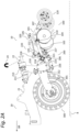
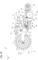
- Figure 5A shows the part of the working machine 20 and the support device 10 from Figure 1 with the pre-tensioning unit 230 displayed in the transport state in a side view (see the arrow marked with "Y" in Figure 1 ).
- Figure 5B shows the part of the working machine 20 and the support device 10 from Figure 1 with the pre-tensioning unit 230 displayed in the first operating state in a side view (see the arrow marked "Y” in Figure 1 )
- Figure 5C shows the part of the working machine 20 and the support device 10 from Figure 1 with the pre-tensioning unit 230 displayed in the second operating state in a side view (see the arrow marked "Y” in Figure 1 ).
- Figure 6 shows the working machine 20 as a whole with the mounted support device 10 from Figure 1 in the second operating state in a third perspective view.
- the work machine 20 is preferably a mobile and/or towable work machine 20 for working a soil B and/or for introducing an agricultural product into a soil B.
- the work machine 20 comprises the machine frame 21, which has a towing device 23 on a front side, via which the work machine 20 can be moved, i.e. pulled, in a transport state and in an operating state in a direction of movement BR.
- the work machine 20 is preferably a towed agricultural work machine 20 in a transport state and in an operating state.
- An agricultural tractor in the form of a wheeled tractor or a crawler tractor serves as a towing vehicle for the work machine 20, for example.
- the working machine 20 comprises a container device 25 for accommodating the agricultural material in the form of fertilizer and/or seed. As can be seen from the illustration in Figure 6 The working machine 20 further comprises a sowing device 26 for sowing the agricultural crop in the soil B and/or for applying fertilizer via the at least one tool device 100. Further units and elements of the sowing device 26 are not identified in more detail.
- the support device 10 as disclosed herein can ensure optimized operation of the work machine 20, wherein, above all, a complex adjustment of the tool device 100 with respect to a defined working depth and/or with respect to a defined tool pressure is avoided. In the present invention, manual steps for adjusting the at least one tool device 100 are obsolete.
- an adjustment of the tool position of the tool device 100 to the floor B and/or to the machine frame 21, and/or an adjustment of the tool pressure of the tool device 100 on the floor B can be adequately detected by means of at least one sensor unit.
- the detected tool position and/or the detected tool pressure can be transmitted by the at least one sensor unit to a control device for regulating and/or controlling the actuator device 22 in order to control and/or regulate the actuator device 22 accordingly in order to adjust the tool device 100 in a defined manner.
- the at least one sensor unit and the control device are not shown in the figures.
- the present invention is not limited to the embodiments described above. Rather, a large number of variants and modifications are possible, which also make use of the inventive concept and therefore fall within the scope of protection.
- the present invention preferably also claims protection for the subject matter and the features of the subclaims independently of the claims referred to.
Landscapes
- Life Sciences & Earth Sciences (AREA)
- Soil Sciences (AREA)
- Environmental Sciences (AREA)
- Engineering & Computer Science (AREA)
- Mechanical Engineering (AREA)
- Agricultural Machines (AREA)
Applications Claiming Priority (1)
| Application Number | Priority Date | Filing Date | Title |
|---|---|---|---|
| DE102023103179.1A DE102023103179A1 (de) | 2023-02-09 | 2023-02-09 | Tragvorrichtung zur montage an einen maschinenrahmen einer landwirtschaftlichen arbeitsmaschine, landwirtschaftliche arbeitsmaschine mit einer solchen tragvorrichtung und verfahren zur verstellung zumindest einer werkzeugeinrichtung einer landwirtschaftlichen arbeitsmaschine |
Publications (1)
| Publication Number | Publication Date |
|---|---|
| EP4424128A1 true EP4424128A1 (fr) | 2024-09-04 |
Family
ID=89834485
Family Applications (1)
| Application Number | Title | Priority Date | Filing Date |
|---|---|---|---|
| EP24155297.5A Pending EP4424128A1 (fr) | 2023-02-09 | 2024-02-01 | Dispositif de support destiné à être monté sur un châssis de machine d'une machine de travail agricole, machine de travail agricole dotée d'un tel dispositif de support et procédé de réglage d'au moins un dispositif de machine de travail agricole |
Country Status (2)
| Country | Link |
|---|---|
| EP (1) | EP4424128A1 (fr) |
| DE (1) | DE102023103179A1 (fr) |
Cited By (1)
| Publication number | Priority date | Publication date | Assignee | Title |
|---|---|---|---|---|
| EP4736618A1 (fr) * | 2024-10-30 | 2026-05-06 | Kverneland Group Soest GmbH | Semoir agricole |
Citations (9)
| Publication number | Priority date | Publication date | Assignee | Title |
|---|---|---|---|---|
| FR2599930A1 (fr) * | 1986-06-11 | 1987-12-18 | Rabewerk Clausing Heinrich | Charrue comportant un dispositif pour regler la distance de coupe et l'orientation du chassis. |
| WO1995015074A1 (fr) * | 1993-12-01 | 1995-06-08 | Martin Niebler | Machine de labourage de sol |
| DE102009058342A1 (de) | 2009-12-15 | 2011-06-16 | Alois Pöttinger Maschinenfabrik Gmbh | Aufhängungsvorrichtung |
| EP2966966B1 (fr) * | 2013-03-15 | 2020-04-15 | Intelligent Agricultural Solutions, LLC | Module de commande |
| DE102019134184A1 (de) * | 2019-11-08 | 2021-05-12 | Horsch Maschinen Gmbh | Landwirtschaftliche Maschine, vorzugsweise zur Bodenbearbeitung und/oder Aussaat und Verfahren zum Steuern und/oder Regeln der Arbeitstiefe einer Werkzeugeinheit |
| EP3868191A1 (fr) | 2020-02-20 | 2021-08-25 | Horsch Maschinen GmbH | Dispositif agricole pourvu d éléments paliers élastiques différents |
| US20220053684A1 (en) * | 2020-08-18 | 2022-02-24 | Deere & Company | Frame adjustment control system and method for downforce |
| US20220053685A1 (en) * | 2020-08-18 | 2022-02-24 | Deere & Company | Frame adjustment control system and method for position |
| EP4000362A1 (fr) * | 2016-12-16 | 2022-05-25 | Agco Corporation | Barre porte-outils de labour en courbes de niveaux d'instrument |
Family Cites Families (1)
| Publication number | Priority date | Publication date | Assignee | Title |
|---|---|---|---|---|
| DE102018124705A1 (de) * | 2018-10-08 | 2020-04-09 | Lemken Gmbh & Co. Kg | Nachrüstkit zum Anbau an ein landwirtschaftliches Gerät |
-
2023
- 2023-02-09 DE DE102023103179.1A patent/DE102023103179A1/de active Pending
-
2024
- 2024-02-01 EP EP24155297.5A patent/EP4424128A1/fr active Pending
Patent Citations (10)
| Publication number | Priority date | Publication date | Assignee | Title |
|---|---|---|---|---|
| FR2599930A1 (fr) * | 1986-06-11 | 1987-12-18 | Rabewerk Clausing Heinrich | Charrue comportant un dispositif pour regler la distance de coupe et l'orientation du chassis. |
| WO1995015074A1 (fr) * | 1993-12-01 | 1995-06-08 | Martin Niebler | Machine de labourage de sol |
| DE102009058342A1 (de) | 2009-12-15 | 2011-06-16 | Alois Pöttinger Maschinenfabrik Gmbh | Aufhängungsvorrichtung |
| EP2966966B1 (fr) * | 2013-03-15 | 2020-04-15 | Intelligent Agricultural Solutions, LLC | Module de commande |
| EP4000362A1 (fr) * | 2016-12-16 | 2022-05-25 | Agco Corporation | Barre porte-outils de labour en courbes de niveaux d'instrument |
| DE102019134184A1 (de) * | 2019-11-08 | 2021-05-12 | Horsch Maschinen Gmbh | Landwirtschaftliche Maschine, vorzugsweise zur Bodenbearbeitung und/oder Aussaat und Verfahren zum Steuern und/oder Regeln der Arbeitstiefe einer Werkzeugeinheit |
| WO2021089197A1 (fr) | 2019-11-08 | 2021-05-14 | Horsch Maschinen Gmbh | Machine agricole, de préférence pour le travail du sol et/ou le semis, et procédé de commande en boucle ouverte et/ou en boucle fermée de la profondeur de travail d'une unité d'outil |
| EP3868191A1 (fr) | 2020-02-20 | 2021-08-25 | Horsch Maschinen GmbH | Dispositif agricole pourvu d éléments paliers élastiques différents |
| US20220053684A1 (en) * | 2020-08-18 | 2022-02-24 | Deere & Company | Frame adjustment control system and method for downforce |
| US20220053685A1 (en) * | 2020-08-18 | 2022-02-24 | Deere & Company | Frame adjustment control system and method for position |
Cited By (1)
| Publication number | Priority date | Publication date | Assignee | Title |
|---|---|---|---|---|
| EP4736618A1 (fr) * | 2024-10-30 | 2026-05-06 | Kverneland Group Soest GmbH | Semoir agricole |
Also Published As
| Publication number | Publication date |
|---|---|
| DE102023103179A1 (de) | 2024-08-14 |
Similar Documents
| Publication | Publication Date | Title |
|---|---|---|
| DE2838829C2 (de) | Mehrschariger Aufsattelpflug | |
| EP0140190A2 (fr) | Semoir | |
| AT508217B1 (de) | Bodenbearbeitungsvorrichtung | |
| EP3242543B1 (fr) | Engin agricole à châssis de roulement supplémentaire | |
| DE102023103179A1 (de) | Tragvorrichtung zur montage an einen maschinenrahmen einer landwirtschaftlichen arbeitsmaschine, landwirtschaftliche arbeitsmaschine mit einer solchen tragvorrichtung und verfahren zur verstellung zumindest einer werkzeugeinrichtung einer landwirtschaftlichen arbeitsmaschine | |
| EP1982854B1 (fr) | Système de bras d'attelage à trois points | |
| EP4023040B1 (fr) | Charrue pourvue de dispositif de réglage combiné pour la largeur de travail et la largeur de la première raie | |
| DE202008018296U1 (de) | Gezogene landwirtschaftliche Maschine | |
| EP3020261A1 (fr) | Combinaison d'un vehicule de traction agricole et d'un semoir direct | |
| DE69419341T2 (de) | Bodenbearbeitungsmaschine | |
| EP1911339B1 (fr) | Char à double disque doté d'un rouleau de guidage en profondeur et accumulateur d'énergie | |
| EP1982853B1 (fr) | Dispositif de bras d'attelage à trois points | |
| EP4272527A1 (fr) | Outil de montage pour l'usinage de champs | |
| DE10120845B4 (de) | Hydromechanische Steuerungsvorrichtung für eine mehrteilige landwirtschaftliche Arbeitsmaschine | |
| DE68923908T3 (de) | Landmaschine. | |
| EP2371194B1 (fr) | Dispositif de répartition de semences et/ou d'engrais | |
| EP0858258A2 (fr) | Machine a semer en ligne pourvue d'un dispositif de reglage du coutre d'ensemencement et du rouleau de pression | |
| EP1982855A1 (fr) | Système de bras d'attelage à trois points | |
| DE102004018591B4 (de) | Bodenbearbeitungsgerät mit Winkelverstellung | |
| EP4586796A1 (fr) | Outil agricole de travail du sol | |
| EP0695495A1 (fr) | Appareil combiné pour le travail du sol | |
| EP3106010B1 (fr) | Dispositif de semis | |
| EP4278875A2 (fr) | Outil pour la culture des champs | |
| EP4147552A1 (fr) | Machine de travail agricole et procédé de fonctionnement d'une machine de travail agricole | |
| DE102021003710A1 (de) | Baugruppe eines auswurfkrümmers für eine erntemaschine |
Legal Events
| Date | Code | Title | Description |
|---|---|---|---|
| PUAI | Public reference made under article 153(3) epc to a published international application that has entered the european phase |
Free format text: ORIGINAL CODE: 0009012 |
|
| STAA | Information on the status of an ep patent application or granted ep patent |
Free format text: STATUS: THE APPLICATION HAS BEEN PUBLISHED |
|
| AK | Designated contracting states |
Kind code of ref document: A1 Designated state(s): AL AT BE BG CH CY CZ DE DK EE ES FI FR GB GR HR HU IE IS IT LI LT LU LV MC ME MK MT NL NO PL PT RO RS SE SI SK SM TR |
|
| STAA | Information on the status of an ep patent application or granted ep patent |
Free format text: STATUS: REQUEST FOR EXAMINATION WAS MADE |
|
| 17P | Request for examination filed |
Effective date: 20250303 |
|
| STAA | Information on the status of an ep patent application or granted ep patent |
Free format text: STATUS: EXAMINATION IS IN PROGRESS |
|
| 17Q | First examination report despatched |
Effective date: 20251010 |
|
| RAP3 | Party data changed (applicant data changed or rights of an application transferred) |
Owner name: HORSCH MASCHINEN SE & CO. KG |