EP3868702A1 - Gabelkopf mit greifvorrichtung und seitlicher bewegung - Google Patents
Gabelkopf mit greifvorrichtung und seitlicher bewegung Download PDFInfo
- Publication number
- EP3868702A1 EP3868702A1 EP19873419.6A EP19873419A EP3868702A1 EP 3868702 A1 EP3868702 A1 EP 3868702A1 EP 19873419 A EP19873419 A EP 19873419A EP 3868702 A1 EP3868702 A1 EP 3868702A1
- Authority
- EP
- European Patent Office
- Prior art keywords
- gripping
- fork
- gripping member
- mobile frame
- frame
- Prior art date
- Legal status (The legal status is an assumption and is not a legal conclusion. Google has not performed a legal analysis and makes no representation as to the accuracy of the status listed.)
- Withdrawn
Links
- 102000004315 Forkhead Transcription Factors Human genes 0.000 title claims abstract description 25
- 108090000852 Forkhead Transcription Factors Proteins 0.000 title claims abstract description 25
- 230000003213 activating effect Effects 0.000 description 3
- 238000005452 bending Methods 0.000 description 2
- 230000005540 biological transmission Effects 0.000 description 2
- 230000001788 irregular Effects 0.000 description 2
- 238000010276 construction Methods 0.000 description 1
- 230000000670 limiting effect Effects 0.000 description 1
- 230000002093 peripheral effect Effects 0.000 description 1
- 230000000087 stabilizing effect Effects 0.000 description 1
- 230000007704 transition Effects 0.000 description 1
Images


Classifications
-
- B—PERFORMING OPERATIONS; TRANSPORTING
- B66—HOISTING; LIFTING; HAULING
- B66F—HOISTING, LIFTING, HAULING OR PUSHING, NOT OTHERWISE PROVIDED FOR, e.g. DEVICES WHICH APPLY A LIFTING OR PUSHING FORCE DIRECTLY TO THE SURFACE OF A LOAD
- B66F9/00—Devices for lifting or lowering bulky or heavy goods for loading or unloading purposes
- B66F9/06—Devices for lifting or lowering bulky or heavy goods for loading or unloading purposes movable, with their loads, on wheels or the like, e.g. fork-lift trucks
- B66F9/075—Constructional features or details
- B66F9/12—Platforms; Forks; Other load supporting or gripping members
- B66F9/14—Platforms; Forks; Other load supporting or gripping members laterally movable, e.g. swingable, for slewing or transverse movements
- B66F9/146—Side shift, i.e. both forks move together sideways relative to fork support
-
- B—PERFORMING OPERATIONS; TRANSPORTING
- B66—HOISTING; LIFTING; HAULING
- B66F—HOISTING, LIFTING, HAULING OR PUSHING, NOT OTHERWISE PROVIDED FOR, e.g. DEVICES WHICH APPLY A LIFTING OR PUSHING FORCE DIRECTLY TO THE SURFACE OF A LOAD
- B66F9/00—Devices for lifting or lowering bulky or heavy goods for loading or unloading purposes
- B66F9/06—Devices for lifting or lowering bulky or heavy goods for loading or unloading purposes movable, with their loads, on wheels or the like, e.g. fork-lift trucks
- B66F9/075—Constructional features or details
- B66F9/12—Platforms; Forks; Other load supporting or gripping members
- B66F9/18—Load gripping or retaining means
Definitions
- the present invention relates to a fork head with a gripping device and lateral movement, especially designed to grip thin objects, such as, for example, the large shafts used in single-axis solar tracker apparatuses.
- the shafts used in single-axis solar tracker apparatuses which, merely by way of reference, can be tubes wish a 150 ⁇ 150 mm square profile, with varying wall thicknesses of between 3 and 6 millimeters, and with lengths of up to 13 meters.
- the shafts used in single-axis solar tracker apparatuses may consist of round profile tubes or any other transverse sectional profile, whether regular or irregular.
- a lifting vehicle such as a forklift with a fork head or the like
- a special grip is necessary for holding and stabilizing the thin object to the fork head of the lifting vehicle.
- CN 206901706 U discloses a fork head with a gripping and lateral movement device.
- the head includes a main frame intended to be fixed to a moving element of an elevator vehicle, a mobile frame movable by a first actuator along a transverse guide fixed to the main frame, two parallel fork arms fixed to the mobile frame, a gripping member pivotally mounted about a horizontal axis supported on the mobile frame, and a second actuator which pivots the gripping element relative to the mobile frame to trap a thin object in a hanging position between the gripping member and the two fork arms.
- the gripping member described in said CN 206901706 U has a length in a direction transverse to the fork arms significantly shorter than the spacing between the two fork arms so that the gripping member can pass between the fork arms. This is a disadvantage since it can produce undesired bending deformations in the thin object when it is pressed by the gripping member at an intermediate point between two support points provided by the fork arms.
- the present invention contributes to the above and other needs by providing a fork head with a gripping and lateral movement device for gripping thin objects, wherein the head comprises a main frame intended to be fixed to a moving element of an elevator vehicle, a mobile frame movable horizontally by a first actuator along a transverse guide fixed to the main frame, a fork having two parallel arms fixed to the mobile frame, and a gripping member mounted on the mobile frame and movable by a second actuator to and from the fork for trapping a thin object in a hanging position between the gripping member and the two fork arms.
- the gripping member has a length in a transverse direction equal to or greater than a fork width defined as a distance between respective opposing outer edges of the two fork arms. Accordingly, the gripping member has end portions superimposed on to portions of the two fork arms.
- the thin object is pressed by the end portions of the gripping member against the corresponding portions of the fork arms, which ensures a firm and stable grip of the thin object without the grip producing bending stresses which can result in undesired deformations in the thin object.
- the thin object once gripped, can be moved laterally with respect to the main frame of the head by means of the first actuator, which facilitates precise positioning of the thin object via the lifting vehicle.
- the gripping member is movable along one or more linear guides fixed to the mobile frame, wherein the linear guides are perpendicular to a support member plane defined by upper surfaces of the two fork arms.
- the support member plane is usually horizontal or approximately horizontal and the linear guides are vertical or approximately vertical.
- each of the linear guides is a guide having a guide body connected to the mobile frame and a telescoping rod connected to the gripping member and slidably inserted into the guide body.
- the linear guides have a reverse arrangement in which the guide body is connected to the gripping member and the telescopic rod is connected to the mobile frame.
- any other guide device for the linear guides may be used.
- the first actuator is a first hydraulic cylinder having a cylinder body connected to the main frame and an extendable rod connected to the mobile frame.
- a first hydraulic cylinder having a cylinder body connected to the main frame and an extendable rod connected to the mobile frame.
- An inverse arrangement is equally possible in which the body of the first hydraulic cylinder is connected to the mobile frame and the extendable rod is connected to the main frame.
- any other type of motor associated with transmission of mechanical movement may be used for the first actuator.
- the second actuator or each second actuator is a second hydraulic cylinder having a cylinder body connected to the mobile frame and an extendable rod connected to the gripping member.
- a second hydraulic cylinder having a cylinder body connected to the mobile frame and an extendable rod connected to the gripping member.
- An inverse arrangement is equally possible, in which the body of the second hydraulic cylinder is connected to the gripping member and the extendable rod is connected to the mobile frame.
- any other type of motor associated with transmission of mechanical movement may be used for the second actuator.
- the gripping member is fixed to a movable arm having a pivotal movement about a horizontal axis
- the second actuator is a second hydraulic cylinder having a cylinder body connected to the mobile frame and an extendable rod connected to the movable arm or vice versa, or any other suitable motor means.
- the gripping member comprises a flat pressure plate parallel to the support member plane or a pressure plate configured in a direction parallel to the support member plane.
- the shape of the pressure plate is adapted to the particular shape of an outer surface of the thin object determined by the shape of the transverse sectional profile thereof.
- the gripping member includes a leading skirt perpendicular to the pressure plate, and consequently perpendicular to the support member plane, extending downwardly from a forward transverse edge of the pressure plate.
- the gripping member further comprises a rear rib extending upwardly from a rear transverse edge of the pressure plate.
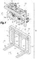
- the reference sign 50 generally designates a fork head with a gripping and lateral movement device according to one embodiment of the present invention, which is intended to grip and manipulate objects in a stable and safe manner.
- the fork head 50 comprises a first subassembly 51 and a second subassembly 52.
- the first subassembly 51 of the fork head 50 includes a main frame 1 intended to be fixed to a mobile element of a lifting vehicle via anchors (not shown), a transverse guide 3 fixed to the main frame 1 and two fork arms 4a, 4b arranged so that they can be moved independently along the transverse guide 3.
- the fork arms 4a, 4b are parallel to a longitudinal direction X corresponding to a rear direction of the lifting vehicle and thus parallel to a direction of movement of the lifting vehicle.
- the transverse guide 3 is oriented in a transverse Y and horizontal direction y and perpendicular to the longitudinal direction X.
- the main frame 1 defines a peripheral frame having an upper bar 11, a lower bar 12, two end posts 13 and a central post 14 extending from the upper bar 11 to the lower bar 12.
- the upper and lower bars 11, 12 are oriented in the transverse direction Y.
- the two end posts 13 and the central post 14 are oriented in a vertical direction Z perpendicular to the longitudinal direction X and to the transverse direction Y.
- the transverse guide 3 has two circular transverse sections extending from each of the end posts 13 to the central post 14.
- Each fork arm 4a, 4b is rigidly attached to one end of a respective vertical element 15 having at its other end a connecting element 16 provided with a circular opening through which the corresponding section of the transverse guide 3 is inserted so that the fork arms 4a, 4b can slide and pivot freely with respect to the transverse guide 3.
- a connecting element 16 provided with a circular opening through which the corresponding section of the transverse guide 3 is inserted so that the fork arms 4a, 4b can slide and pivot freely with respect to the transverse guide 3.
- a curved transition section 17 that interferes with the lower bar 12 of the main frame to limit the pivoting of the fork arm 4a, 4b.
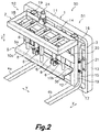
- the second subassembly 52 of the fork head 50 comprises a mobile frame 2 having an upper horizontal structure 18 and two rear posts 19 oriented in the vertical direction Z.
- the two rear posts 19 are fixed to the upper frame 18 engaging with braces 20.
- Each of the rear posts 19 has a first bracket 21 configured to be attached to one of the vertical elements 15 which in turn are attached to the fork arms 4a, 4b.
- the first subassembly 51 can slide and pivot together with the fork arms 4a, 4b along the transverse guide 3.
- a first actuator which, in the illustrated embodiment, is comprised of a first hydraulic cylinder 7 having a cylinder body connected to a support member 22 which has a second bracket 23 fixed to the central post 14 of the main frame 1 and an extendable rod connected to one of the rear posts 19 of the mobile frame 2.
- connection of the first hydraulic cylinder 7 could be reversed, i.e., with cylinder body connected to the rear post 19 and extendable rod connected to the support member 22.
- Both the first brackets 21 and the second bracket 23 include tightening screws by which it is possible to adjust the position of the second subassembly 52 relative to the first subassembly 51 in the vertical direction Z.
- activating the first hydraulic cylinder 7 moves the second subassembly 52 horizontally together with the fork arms 4a, 4b with respect to the main frame 1 of the first subassembly 51 along the transverse guide 3 parallel to the transverse direction Y.
- the second subassembly 52 comprises a mobile gripping member 5 installed on the mobile frame 2 in a position facing the upper surfaces of the two fork arms 4a, 4b defining a support member plane.
- the gripping member 5 comprises a pressure plate 9 parallel to the support member plane.
- the pressure plate 9 has front and rear transverse edges parallel to the transverse direction Y.
- the gripping member 5 further comprises a front skirt 10a perpendicular to the pressure plate 9 which extends downwardly from the front transverse edge of the pressure plate 9 and a rear rib 10b extending upwardly from the rear transverse edge of the pressure plate 9.
- the gripping member 5 can be moved in the vertical direction Z along the linear telescopic guides 6 by means of second actuators, such as second hydraulic cylinders 8.
- the linear guides 6 are perpendicular to the pressure plate 9 and consequently parallel to the vertical direction Z.
- Each of the linear guides 6 has a guide body connected to the mobile frame 2 and a telescopic rod slidably inserted into the guide body and connected to the gripping member 5.
- the second hydraulic cylinders 8 have a cylinder body connected to the mobile frame 2 and an extendable rod connected to the gripping member 5.
- connection of the linear guides 6 could be reversed, i.e., with the guide body connected to the gripping member 5 and the telescopic rod connected to the mobile frame 2.
- connection of the second hydraulic cylinders 8 could be reversed, i.e., with the cylinder body connected to the gripping member 5 and the extendable rod connected to the mobile frame 2.
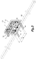
- activating the second hydraulic cylinders 8 in a first direction causes a movement of the gripping member 5 toward the fork arms 4a, 4b by a path sufficient to trap a thin object 40 between the gripping member 5 and the two fork arms 4a, 4b, the thin object 40 being arranged in a hanging position and oriented in a direction parallel to the transverse direction Y.
- Activating the second hydraulic cylinders 8 in a second opposite direction causes a movement of the gripping member 5 away from the fork arms 4a, 4b so as not to interfere with the thin object 40.
- a six-way valve 24 mounted on the upper frame 18 of the mobile frame 2 is a six-way valve 24 connected to the first hydraulic cylinder 7 and to the second hydraulic cylinders 8 via flexible conduits (not shown) connectable to a hydraulic system of the lifting vehicle.
- the operation of the first hydraulic cylinder 7 and the second hydraulic cylinders 8 is controlled via the six-way valve 24.
- the gripping member 5 has a length L in the transverse direction Y equal to or greater than a fork width W defined as a distance between respective opposite outer edges of the two fork arms 4a, 4b in the transverse direction Y and, and further the gripping member 5 has end portions 5a, 5b superimposed on portions of the two fork arms 4a, 4b.
- Fig. 3 shows the fork head of the present invention with the gripping member 5 in an active position gripping a thin object consisting of a square profile tube such as those used for example as turning shafts in single-axis solar tracker apparatuses.
- these square profile tubes can have a transverse sectional size of about 150 x 150 millimeters, with varying wall thicknesses of between 3 and 6 millimeters, and with lengths of up to 13 meters.
- the thin objects may consist of square, round or any other shape of regular or irregular transverse section.
Landscapes
- Engineering & Computer Science (AREA)
- Transportation (AREA)
- Structural Engineering (AREA)
- Civil Engineering (AREA)
- Life Sciences & Earth Sciences (AREA)
- Geology (AREA)
- Mechanical Engineering (AREA)
- Forklifts And Lifting Vehicles (AREA)
- Load-Engaging Elements For Cranes (AREA)
Applications Claiming Priority (2)
| Application Number | Priority Date | Filing Date | Title |
|---|---|---|---|
| ES201831560U ES1223094Y (es) | 2018-10-16 | 2018-10-16 | Cabezal de horquilla con dispositivo de agarre y desplazamiento lateral |
| PCT/ES2019/070676 WO2020079296A1 (es) | 2018-10-16 | 2019-10-07 | Cabezal de horquilla con dispositivo de agarre y desplazamiento lateral |
Publications (2)
| Publication Number | Publication Date |
|---|---|
| EP3868702A1 true EP3868702A1 (de) | 2021-08-25 |
| EP3868702A4 EP3868702A4 (de) | 2022-07-06 |
Family
ID=65003673
Family Applications (1)
| Application Number | Title | Priority Date | Filing Date |
|---|---|---|---|
| EP19873419.6A Withdrawn EP3868702A4 (de) | 2018-10-16 | 2019-10-07 | Gabelkopf mit greifvorrichtung und seitlicher bewegung |
Country Status (8)
| Country | Link |
|---|---|
| US (1) | US11396445B2 (de) |
| EP (1) | EP3868702A4 (de) |
| CN (1) | CN216472092U (de) |
| AR (1) | AR121422A4 (de) |
| BR (1) | BR212021007004Y1 (de) |
| CL (1) | CL2021000921A1 (de) |
| ES (1) | ES1223094Y (de) |
| WO (1) | WO2020079296A1 (de) |
Families Citing this family (7)
| Publication number | Priority date | Publication date | Assignee | Title |
|---|---|---|---|---|
| US12282334B2 (en) | 2022-12-21 | 2025-04-22 | Built Robotics Inc. | Autonomous pile driver apparatus and method |
| US12216468B2 (en) | 2022-12-21 | 2025-02-04 | Built Robotics Inc. | Quality control operation for autonomous pile driving system |
| US12305353B2 (en) | 2022-12-21 | 2025-05-20 | Built Robotics Inc. | Pile platforms for autonomous pile driver vehicle |
| US12129624B2 (en) * | 2022-12-21 | 2024-10-29 | Built Robotics Inc. | Pile manipulation tool for autonomous pile driver vehicle |
| US11822342B1 (en) | 2022-12-21 | 2023-11-21 | Built Robotics Inc. | Obstacle map for autonomous pile driving system |
| US11788247B1 (en) | 2022-12-21 | 2023-10-17 | Built Robotics Inc. | Basket assembly operation for autonomous pile driving system |
| US12434955B2 (en) * | 2023-08-21 | 2025-10-07 | Harold Dewayne Morgan | Jaw attachment for a pallet lift vehicle |
Family Cites Families (17)
| Publication number | Priority date | Publication date | Assignee | Title |
|---|---|---|---|---|
| US2684165A (en) * | 1952-06-09 | 1954-07-20 | Blackwelder Mfg Co | Laterally shiftable fork lift for tractors |
| US2772800A (en) * | 1954-01-07 | 1956-12-04 | Clark Equipment Co | Load stabilizer for lift trucks |
| US2807382A (en) * | 1955-01-07 | 1957-09-24 | 1250 West 80Th Street Corp | Industrial lift truck with load clamp |
| US2875912A (en) * | 1956-01-23 | 1959-03-03 | Albert W Thresher | Attachment for a lift truck |
| US2959313A (en) * | 1957-08-01 | 1960-11-08 | Raymond B Bentley | Fork lift stacker |
| US3039635A (en) * | 1957-11-26 | 1962-06-19 | Clark Equipment Co | Attachment for lift truck |
| US3024929A (en) * | 1961-01-23 | 1962-03-13 | William L Shimmon | Box turning device for fork-lift trucks |
| US3455476A (en) * | 1967-03-10 | 1969-07-15 | Wortham Machinery Co | Attachment for lift truck |
| US3438525A (en) * | 1967-06-12 | 1969-04-15 | Cascade Corp | Apparatus and method for handling a load supported on a pallet |
| US4116349A (en) | 1977-04-07 | 1978-09-26 | Durham Harvey E | Fork lift load clamping and stabilizing device |
| JPS56103599U (de) | 1979-12-31 | 1981-08-13 | ||
| US4354795A (en) * | 1981-02-13 | 1982-10-19 | Dutra Jr Joseph G | Load stabilizer assembly with pivotal mount for a forklift truck |
| CA2044895C (en) * | 1991-06-18 | 1994-11-08 | Antonio Gallo | Gripping device and method of use |
| KR970004082Y1 (ko) * | 1993-11-16 | 1997-04-29 | 대우중공업 주식회사 | 신축범위가 증대된 화물 고정장치 |
| JP4178662B2 (ja) | 1999-05-21 | 2008-11-12 | 株式会社豊田自動織機 | フォークリフトのサイドシフト装置 |
| CN103010765A (zh) | 2012-12-31 | 2013-04-03 | 陈兴宁 | 货叉式夹砖器 |
| CN206901706U (zh) | 2017-06-20 | 2018-01-19 | 安徽好运机械有限公司 | 一种带侧移功能的钢管夹属具 |
-
2018
- 2018-10-16 ES ES201831560U patent/ES1223094Y/es active Active
-
2019
- 2019-10-07 US US17/285,468 patent/US11396445B2/en active Active
- 2019-10-07 EP EP19873419.6A patent/EP3868702A4/de not_active Withdrawn
- 2019-10-07 WO PCT/ES2019/070676 patent/WO2020079296A1/es not_active Ceased
- 2019-10-07 BR BR212021007004-0U patent/BR212021007004Y1/pt active IP Right Grant
- 2019-10-07 CN CN201990001088.5U patent/CN216472092U/zh active Active
- 2019-10-14 AR ARM190102915U patent/AR121422A4/es active IP Right Grant
-
2021
- 2021-04-14 CL CL2021000921A patent/CL2021000921A1/es unknown
Also Published As
| Publication number | Publication date |
|---|---|
| ES1223094U (es) | 2019-01-16 |
| AR121422A4 (es) | 2022-06-08 |
| EP3868702A4 (de) | 2022-07-06 |
| CL2021000921A1 (es) | 2021-09-10 |
| CN216472092U (zh) | 2022-05-10 |
| BR212021007004Y1 (pt) | 2024-01-23 |
| BR212021007004U2 (pt) | 2021-09-21 |
| US11396445B2 (en) | 2022-07-26 |
| US20210380383A1 (en) | 2021-12-09 |
| ES1223094Y (es) | 2019-04-09 |
| WO2020079296A1 (es) | 2020-04-23 |
Similar Documents
| Publication | Publication Date | Title |
|---|---|---|
| US11396445B2 (en) | Fork head with gripping device and lateral movement | |
| US8671626B1 (en) | Apparatus and method for a drilling rig assembly | |
| EP2813447B1 (de) | Klemmvorrichtungen | |
| US20120222386A1 (en) | Construction panel positioning and support system and tools | |
| US7354023B1 (en) | Tool and part holding tray | |
| CN107207230A (zh) | 负载固定装置 | |
| JP2006504056A5 (de) | ||
| US8225693B2 (en) | Control lever mechanism adapted to be mounted to a cowl of a materials handling vehicle | |
| US20080224109A1 (en) | Puller device | |
| JP6604673B1 (ja) | ハッカー | |
| EP3587709B1 (de) | Einstellvorrichtung und anordnung mit der einstellvorrichtung | |
| JP6371676B2 (ja) | 柱材引抜装置 | |
| US6418567B1 (en) | Seating assist apparatus | |
| US10281062B2 (en) | Vertical compression assembly and method of installing a vertical compression assembly | |
| CN111517236B (zh) | 伸缩机构、臂架及高空作业设备 | |
| US20110206457A1 (en) | Apparatus and method for guiding and containing a boat for use in conjunction with a boat-docking device | |
| JP5653717B2 (ja) | ヤットコ用アダプタ | |
| KR20140038259A (ko) | 보강시트 고정장치 | |
| JP2000272892A (ja) | 屈伸ブーム | |
| CN210217128U (zh) | 大钢模板的固定装置 | |
| KR970001201A (ko) | 자동차 배터리 운반장치 | |
| EP3076773B1 (de) | Schienenanordnung | |
| CN222972194U (zh) | 一种机械手 | |
| EP2995388B1 (de) | Ein absaugungsarm | |
| CN111463713A (zh) | 一种手掌开合装置及巡线车 |
Legal Events
| Date | Code | Title | Description |
|---|---|---|---|
| STAA | Information on the status of an ep patent application or granted ep patent |
Free format text: STATUS: THE INTERNATIONAL PUBLICATION HAS BEEN MADE |
|
| PUAI | Public reference made under article 153(3) epc to a published international application that has entered the european phase |
Free format text: ORIGINAL CODE: 0009012 |
|
| STAA | Information on the status of an ep patent application or granted ep patent |
Free format text: STATUS: REQUEST FOR EXAMINATION WAS MADE |
|
| 17P | Request for examination filed |
Effective date: 20210426 |
|
| AK | Designated contracting states |
Kind code of ref document: A1 Designated state(s): AL AT BE BG CH CY CZ DE DK EE ES FI FR GB GR HR HU IE IS IT LI LT LU LV MC MK MT NL NO PL PT RO RS SE SI SK SM TR |
|
| DAV | Request for validation of the european patent (deleted) | ||
| DAX | Request for extension of the european patent (deleted) | ||
| A4 | Supplementary search report drawn up and despatched |
Effective date: 20220608 |
|
| RIC1 | Information provided on ipc code assigned before grant |
Ipc: B66F 9/14 20060101ALI20220601BHEP Ipc: B66F 9/18 20060101AFI20220601BHEP |
|
| GRAP | Despatch of communication of intention to grant a patent |
Free format text: ORIGINAL CODE: EPIDOSNIGR1 |
|
| STAA | Information on the status of an ep patent application or granted ep patent |
Free format text: STATUS: GRANT OF PATENT IS INTENDED |
|
| INTG | Intention to grant announced |
Effective date: 20240606 |
|
| STAA | Information on the status of an ep patent application or granted ep patent |
Free format text: STATUS: THE APPLICATION IS DEEMED TO BE WITHDRAWN |
|
| 18D | Application deemed to be withdrawn |
Effective date: 20241008 |