EP3868998A1 - Raccordement de deux membres de tige de forage d'une tige de forage destiné au forage du sol - Google Patents
Raccordement de deux membres de tige de forage d'une tige de forage destiné au forage du sol Download PDFInfo
- Publication number
- EP3868998A1 EP3868998A1 EP21167590.5A EP21167590A EP3868998A1 EP 3868998 A1 EP3868998 A1 EP 3868998A1 EP 21167590 A EP21167590 A EP 21167590A EP 3868998 A1 EP3868998 A1 EP 3868998A1
- Authority
- EP
- European Patent Office
- Prior art keywords
- drill string
- pull
- plug
- head
- lock
- Prior art date
- Legal status (The legal status is an assumption and is not a legal conclusion. Google has not performed a legal analysis and makes no representation as to the accuracy of the status listed.)
- Granted
Links
Images
Classifications
-
- E—FIXED CONSTRUCTIONS
- E21—EARTH OR ROCK DRILLING; MINING
- E21B—EARTH OR ROCK DRILLING; OBTAINING OIL, GAS, WATER, SOLUBLE OR MELTABLE MATERIALS OR A SLURRY OF MINERALS FROM WELLS
- E21B17/00—Drilling rods or pipes; Flexible drill strings; Kellies; Drill collars; Sucker rods; Cables; Casings; Tubings
- E21B17/02—Couplings; joints
- E21B17/04—Couplings; joints between rod or the like and bit or between rod and rod or the like
- E21B17/046—Couplings; joints between rod or the like and bit or between rod and rod or the like with ribs, pins, or jaws, and complementary grooves or the like, e.g. bayonet catches
- E21B17/0465—Couplings; joints between rod or the like and bit or between rod and rod or the like with ribs, pins, or jaws, and complementary grooves or the like, e.g. bayonet catches characterised by radially inserted locking elements
Definitions
- the invention relates to a system and a method for connecting two drill string members of a drill string for earth drilling and the use of a pull-off safety device when connecting two drill string members of a drill string for earth drilling.
- a drill head In the case of rod-based drilling in the ground, in particular for the production of so-called horizontal bores, which can run essentially parallel to or at a relatively small angle of inclination to the surface of the earth, a drill head is driven by a drill rod, the so-called drill string, from a drive device arranged on the surface or in a pit driven forward.
- the drill rods used here usually consist of individual, interconnected rod sections which - according to the drilling path - are gradually attached to the rear end of the drill rod that has already been drilled and connected to it.
- the rod sections can be connected by means of a threaded connection and / or a plug connection.
- a plug-in connection is described which - similar to a threaded connection - is based on helical projections / grooves running on a threaded plug with a circular cross section or in a corresponding threaded bushing, the projections / grooves being designed in such a way that the self-locking characteristic of a threaded connection is not occurs.
- the invention was based on the object of specifying an improved possibility for connecting two drill string members of a drill string for earth drilling, which in particular enables a simpler design and / or a safe and / or simple connection.
- the invention is based on the idea of specifying a possibility for connecting two drill string members which combines both a plug connection and a screw connection with one another.
- the two drill string members can be plugged into one another and an anti-pull device is used, which is exposed at the end and can be screwed.
- the invention provides a system for connecting two drill string members of a drill string for earth drilling, one drill string member having a plug element arranged at the end in the form of a plug and the other drill string member having a plug element arranged at the end in the form of a socket.
- the plug and socket are designed in such a way that the two drill string members have through holes that are aligned with one another, through which a pull-out lock can be inserted.
- the pull-off safety device has a head and an end spaced apart from the head, a thread being formed at the end of the pull-off safety device.
- the head and end of the peel-off safety device are spaced apart from one another in such a way that the end of the pull-off safety device is exposed at the end when the pull-off safety device is inserted into the through holes.
- the term “drill string” comprises a string which has an earth boring tool and a rod and which can be moved by means of an earth boring device or a drive device in order to drill an earth hole through the earth.
- linkage includes not only rigid, individual, directly or indirectly connected, linkage sections with linkage, but in particular all force transmission elements that can be used in an earth boring device.
- pipe section in the sense of the description comprises an element which extends along a longitudinal axis and which is part of the pipe or of a drill string for earth drilling.
- the rod section can be designed as an element arranged on the front side in the drill string with an assigned function (transmitter housing or the like) or as an element (only mechanically) extending the drill string as a rod section.
- the rod assembly section can comprise mechanical channels, for example for drilling fluid, electrical lines, electrical elements and / or electronic elements.
- earth boring tool comprises a drill head which is arranged at the front end of the drill string and in which movable parts can be provided. However, it can also be provided that the earth boring tool has an immovable or rigid or largely immovable or rigid outer contour.
- Erdbohrvoriques includes in the sense of the description any device that can move in particular a drill string having rods in an existing or to be created channel in the ground in order to create or expand a bore, in particular a horizontal bore, or to create lines or other long Pulling bodies into the ground.
- An earth drilling device can comprise a drive device that drives a drill string in a pulling and / or pushing manner. It can additionally or alternatively be provided that the drive device drives the drill string in a rotational manner.
- horizontal drilling in the sense of the description includes in particular any type of existing or to be created, preferably horizontal, channels in a body, in particular underground channels including earth bores, rock bores or underground lines as well as underground or above-ground pipelines and water channels that run through Establish the use of a suitable earth boring device or have it pulled in.
- drill string member refers to a portion of the drill string that is releasably connectable to other portions of the drill string.
- a drill string member can be a string section.
- a drill string link is a connecting element for two rod sections which are indirectly connected to one another via the connecting element.
- plug and socket include in the sense of the description an embodiment as one element of a pair of mechanical coupling elements, one of which (“plug”) can be at least partially inserted into the other (“socket") to the Form connection.
- the plug and / or socket can have stop or contact surfaces on the circumferential side, which are in contact with stop or contact surfaces on the other element and can act on these alternately in the event of thrust or pressure.
- a drill string member advantageously has a plug element in the form of a plug at one end and a plug element in the form of a socket at the other end.
- the end of the drill string member has plug-in elements of the same shape, so that the drill string member has a plug-in element in the form of a plug at both ends or a plug-in element in the form of a socket at both ends.
- a "through hole” is a through hole that differs from a blind hole.
- the through hole does not necessarily have to have the same diameter or the same contour over the entire length.
- the contour surrounding the through hole can be ring-shaped, elliptical, non-circular, polygonal or a mixed shape of the aforementioned shapes. If the term “aligned” is selected for the through holes in the description, this is to be understood as meaning that the through hole formed in the plug at least partially overlaps the through hole in the socket.
- the through holes are essentially coaxial with one another; minor deviations, in particular manufacturing-related tolerances, are possible.
- the through-holes or the through-hole in the socket have a larger cross-sectional area in relation to the longitudinal axis of the through-hole than the cross-sectional area at least in a section of the through-hole in the plug.
- an edge region of the head of the anti-pull device can rest on an edge in the through hole, in particular in the section of the plug, when the anti-pull device is inserted through the aligned through holes.
- the through hole in the socket and the plug is preferably aligned essentially transversely to the longitudinal axis of the drill string member, an angle in the angular range between 70 ° and 110 ° being preferred, An angle close to 90 ° is particularly preferred, and the angle 90 ° is very particularly preferred.
- Numbers in the sense of the description are information that can have a tolerance of +/- 10%, so that the number describes not only one value, but a range of values in order to take account of tolerance ranges that may be production-related.
- the term “pull-off protection” includes an elongated or rod-shaped element which can be inserted into the plug and socket through the aligned through-holes.
- the peel-off safety device has a head which, in particular compared to a shaft section, has an enlarged cross-sectional area transverse to the longitudinal axis of the pull-off safety device.
- the area of the head facing the end with its enlarged cross-sectional area compared to the end and a shank section can have an edge-side bearing surface which can in particular rest on an outwardly (essentially radially) directed outer surface of the plug, this outer surface of the plug within a receptacle of the Connector can be present.
- the end spaced from the head is threaded. The end is exposed at the end when the pull-off lock is inserted. The end and / or thread can be accessed from the outside.
- the plug can form a support for the head of the pull-off lock when the pull-off lock is plugged in.
- the plug can have a receptacle for the head so that the head of the pull-off safety device can be at least partially sunk into the plug.
- An improved transmission of the forces via the drill string members of the system is made possible, with compressive forces being able to be transmitted via a stop of the plug connection between the plug and socket. Rotational forces can be transmitted via a profile formed within the plug connection between the plug and socket. Tensile forces are transmitted via the pull-off protection.
- the stop for transmitting the compressive forces can be formed by means of an edge of the socket and / or the plug, which are at least partially in contact with one another in the plugged-together state.
- the thread used to secure the pull-off protection does not have to come into engagement with the drill string member itself, but an externally accessible further element can be used which can be renewed independently of the drill string members. Should the thread or the pull-off lock itself have to be renewed, the drill string link itself does not need to be reworked or serviced.
- a thread is provided in the plug element in the form of a plug at the end of the through hole, which thread is designed to interact with a thread of the pull-off safety device.
- the term “interaction” encompasses such a configuration that the pull-off lock has, at least in sections, an external thread which can cooperate with the internal thread formed at the end of the through hole of the plug.
- a screw connection can be formed via a screw connection between the pull-off lock and the thread present at the end in the through-hole of the plug, which is arranged in particular at the rear end of the through-hole of the plug in the plug-in direction can form.
- this securing device can comprise an additional securing element which can be designed in the form of a (wedge) locking washer, a spring ring, a serrated lock washer or the like.
- the securing element can rest on the head of the pull-off safeguard.
- a securing element can first be pushed onto the pull-off safeguard.
- the anti-pull device can then be inserted into the aligned through holes of the socket and plug and screwed in with the thread formed at least at the end on the through hole of the plug and, in particular, tightened.
- the securing element present at the head of the pull-off lock can largely prevent the pull-off lock from coming loose.
- the securing element is designed as a wedge lock washer, a securing effect can be achieved in that different angles (ratios) exist between the wedge lock washer and the thread pitch.
- ratios there can be an angle ⁇ on the wedge locking washer which is greater than the thread pitch ⁇ of the thread. If it is described in the description that a thread "at the end" is provided on the through hole of the plug, this does not preclude the thread from extending through the entire through hole of the plug.
- an only end-side arrangement or formation of a thread on the through hole with an otherwise thread-free through hole of the plug offers the advantage that the thread in the form of an internal thread on the through hole only extends over a short area, which simplifies production.
- the end of the anti-peeling device which is spaced from the head of the anti-peeling device, is exposed by means of the through-hole formed in the bushing and can also be provided with a thread.
- This thread can be configured identically to the thread which cooperates with the internal thread of the through hole of the plug. This enables a simple design to be achieved.
- another thread in addition to the There is an external thread which cooperates with the internal thread formed at the end on the through hole of the plug.
- the pull-off protection can have two different threads at its end.
- the exposed thread can interact with an internal thread of a counterpart, in particular to prevent a first (plug has no internal thread interacting with the pull-off lock) or a second safeguard (plug has an internal thread that interacts with the pull-off lock) against loss To form pull-off protection.
- the head of the anti-pull device is designed to interact with a tool, in particular a tool that acts "from above" on the anti-pull device.
- a tool in particular a tool that acts "from above” on the anti-pull device.
- tools can in particular be preferred which act in a direction which essentially corresponds to the longitudinal direction of the pull-off lock on the side of the pull-off lock that is spaced apart from the end of the pull-off lock.
- tools are preferred which act on an end face of the head which is exposed essentially in the longitudinal direction of the pull-off safety device.
- a tool that engages only in a recess of the head which is formed in the longitudinal direction of the pull-off safety device, enables the tool to engage in this cut-out and allows the pull-off safety device to rest with its head at least partially on the circumference of one or both drill rod members.
- a receptacle formed on the pull-off protection for interaction with an Allen key, hexagon socket, Torx or XZN (internal multi-tooth profile) is preferred.
- the head of the anti-pull device can be at least partially sunk into a receptacle on the socket.
- the cross-sectional area of the drill string members is not significantly increased or that there is no change in the cross-sectional area compared to a drill string member without a pull-off safety device.
- a receptacle in the socket provides the possibility that the head of the anti-pull device can rest against the socket on the circumferential side, so that the tensile forces can be transmitted not only via a shaft section of the anti-pull device, but also via the head of the anti-pull device.
- the inside contour of the receptacle on the socket can at least partially correspond to the outside contour of the head of the anti-pull device or be adapted to it.
- a form fit is possible.
- the cross section of the head of the The pull-off protection and the cross section of the receptacle can be round, in particular in the form of a circle. Other shapes are possible, for example the head and / or receptacle can be elliptical, polygonal, rectangular, square or polygonal or have mixed forms thereof.
- the plug can preferably also have a receptacle for the head of the pull-off lock, so that the head of the pull-off lock can be sunk at least partially in the direction of the extension of the through hole in the plug.
- the receptacle in the plug can be configured in accordance with the receptacle in the socket.
- securing elements it is possible for securing elements to be pushed onto the pull-off safeguard in the longitudinal direction, one of which in particular can rest on the edge of the head of the pull-off safeguard.
- a securing element can be pushed onto the exposed end of the pull-off lock when the pull-off lock is inserted and / or screwed on.
- Such a securing element was described above in connection with the installation on the head.
- the securing element to be pushed onto the exposed end of the peel-off safeguard can be configured just like the securing element described above with reference to the contact with the head of the peel-off safeguard.
- the counterpart can be replaced without the need to replace either or both of the drill string members.
- a securing element pushed onto the exposed end can represent an additional securing which offers a release of the pull-off safeguard in addition to the securing by means of the counterpart.
- a counterpart can be screwed onto the thread formed at the end of the pull-off lock and, in interaction with the screw connection between the pull-off lock and the end-side thread on the plug, can act like a lock nut. In this way, a safeguard against losing the pull-off lock can be formed.
- the securing element pushed onto the exposed end of the pull-off safeguard which can be pushed onto the pull-off safeguard in front of the counterpart, can be a third securing device.
- the counterpart is designed to interact with a tool.
- the tool can attack the counterpart - as well as the head of the anti-pull device - "from above".
- the tool does not act on the side of the counterpart.
- an upwardly oriented (essentially longitudinally oriented, spaced from the end) recess is provided, into which the tool can engage. This makes it possible for the counterpart to bear against one or both of the drill rod members at least partially on the circumferential side. In particular, the counterpart can at least partially abut the socket on the circumferential side.
- tools are preferred which act exclusively on the end face of the counterpart, which is present essentially in the longitudinal direction to the thread cooperating with the thread configured at the end of the pull-off safety device.
- Effects of a tool from the side for example in the form of a socket wrench or a wrench, are possible, but not preferred, since they attack from the side and space is required for this.
- a tool engaging in a recess of the counterpart which is formed in the longitudinal direction, enables the tool to engage in this recess and allows the counterpart, in particular, to rest at least partially circumferentially on one or both drill rod members.
- a receptacle formed on the counterpart to interact with an Allen key, hexagon socket, Torx or XZN (internal multi-tooth profile) is preferred.
- the counterpart can be at least partially sunk into a receptacle on the socket. In this way it can be achieved that no substantial increase in the cross-sectional area of the drill string member is achieved, or that there is no increase in the cross-sectional area of the drill string member. Partial countersinking of the counterpart in a receptacle formed in the plug is also possible.
- a receptacle for the head of the anti-pull device or a receptacle for the counterpart is achieved by means of a dimension of the through hole that is adapted to the outer dimensions of the edge of the head or of the counterpart.
- a receptacle can thus be formed by means of a cross section of the through hole that is adapted to the cross section of the head or the counterpart.
- the edge of the receptacle can essentially correspond to the edge of the head or the counterpart, or be larger than this. The reception can be terminated by reducing the cross section of the through hole.
- a shaft section is provided on the pull-off protection between the head and the end, which is designed without a thread and / or the circumference of which is larger than the circumference of the end.
- the stability can be improved by not machining and / or by choosing the dimensions of the shaft section. Because the circumference at the end is reduced compared to the circumference at the shaft section, a material weakening in the area of the plug is reduced or excluded. Any tensile loads on the drill string members, which are at least partially transmitted via the pull-off safety device, can be transmitted through the shank section, which is reinforced.
- the through holes of the socket and / or of the plug are designed without threads. This enables a particularly simple design of the drill string members. In particular, there is no need to form a thread in the through hole with which the pull-off lock can interact. The work step of creating or forming a thread on the drill string member is eliminated. The maintenance of the drill string members is unaffected by the threadless design of the through holes.
- a thread is formed at the end of the through hole of the plug, which thread is in particular an internal thread and which is designed to interact with a thread of the pull-off safety device. In this way, a safeguard against losing the pull-off safeguard can be made possible, which is effective.
- the through holes are formed essentially transversely to the longitudinal axis of the drill string and / or are formed centrally in cross section. This enables a stability of the engagement and the connection under tensile load.
- the loading of the through holes, especially for the plug, takes place in the area where most of the material is present.
- a tensile load can be transmitted over the entire width and twisting is almost impossible.
- a plurality of through holes spaced apart in the longitudinal direction of the drill string members are formed in at least one of the plug-in elements.
- the plug and socket each have a profile on the circumference, which can interact when the plug connection is formed to transmit clockwise and / or counterclockwise rotational forces about the longitudinal axis.
- the profile allows the transmission of rotational forces between the drill string members when the plug connection is formed.
- the plug has contact surfaces on the outer circumference which can be brought into engagement with contact surfaces in the socket, the contact surfaces being able to extend at least partially in the radial direction in order to be able to transmit the rotational forces.
- In the radial direction within the meaning of the description, includes contact surfaces which can have an angle of 0 ° to 45 ° to the radial direction.
- the profile can be at least partially unchanged in the insertion direction.
- the profile makes it possible to transfer rotational forces from one drill string member to the other drill string member.
- a profile can be provided which is at least partially unchanged in the longitudinal direction.
- the profile can be changed when viewed in the longitudinal direction, for example by selecting a plug connection in which the spiral has projections / grooves running on a threaded plug with a circular cross section or in a corresponding threaded bushing. Profiles that are unchanged in sections in the longitudinal direction are particularly preferred. A simplified production can hereby be made possible. A toothed shaft profile is preferably used.
- the invention also provides a method of joining two drill string members of a drill string for earth drilling.
- the two drill string members are plugged into one another at the ends and aligned so that through holes arranged in the drill string members are aligned, with a pull-out lock being inserted through the through holes, the exposed end of which can be screwed to a counterpart.
- a method is created with which, in particular, the risk of injury for the user who connects the drill string members to one another is reduced, and yet a secure and resilient connection that can be made easily and / or is simply set up is possible.
- the invention also provides a use of a peel lock when joining two drill string members of a drill string for earth drilling.
- the two drill string members are inserted one into the other at the ends and are aligned in such a way that through holes arranged in the drill string members are aligned.
- the anti-pull device is inserted through the through-holes, a pull-out device being used, the exposed end of which can be screwed to a counterpart.
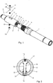
- Fig. 1 shows in an isometric representation two drill string members 1, 2 of a drill string for earth drilling.
- the two drill string members 1, 2 are shown in a position in which they can be connected to one another.
- the drill string member 1 has a plug element 3 arranged at the end in the form of a plug 4.
- the drill string member 2 has a plug element 5 arranged at the end in the form of a bush 6.
- Plug 4 and socket 6 are designed to form a plug connection.
- the outer circumference or the outer contour of the plug 4 is at least partially adapted to the inner contour of the socket 6.
- the outer contour of the plug 4 can essentially correspond to the inner contour of the socket 6.
- a profile is formed in the circumferential direction on the connector 4, which profile has contact surfaces which have a maximum deviation of 45 ° from a radial direction.
- the socket 6 has a profile 8 cooperating with the profile 7 of the plug 4 in the circumferential direction, which profile also has contact surfaces which have a maximum deviation of 45 ° from a radial direction.
- the profiles 7, 8 are designed as splined shaft profiles, which are at least partially formed unchanged in the longitudinal direction of the drill string members.
- a stop 9 which is shown closed in the exemplary embodiment, but can also be interrupted, is formed on the drill string member 1 for the drill string member 2.
- the drill string member 2 can with its bush 6 on the edge with the circumferential Edge 10, which can also be interrupted, rest against the stop 9 in order to transmit compressive forces in the longitudinal direction of the drill string members 1, 2.
- Two through holes 11 are formed on the plug 4 and are at a defined distance from the stop 9.
- Two through holes 12 are formed on the bush 6 of the drill string member 2, each of which is at a defined distance from the edge 10.
- the through holes 11, 12 are each arranged centrally parallel to one another.
- the through holes 11 on the plug 4 are aligned with the through holes 12 on the socket 6, since the distance from the stop 9 or the edge 10 is selected accordingly.
- the through holes 11, 12 form a through hole which extends through the plug 4 and socket 6 and which has a different cross section over its extension.
- a removal lock 13 can be inserted through the aligned through holes 11, 12, which prevents the plug 4 from being pulled from the socket 6 or the socket 6 from the plug 4. Tensile forces can be transmitted between the two drill string members 1, 2 through the pull-off lock 13.
- the pull-off lock 13 has a head 14 and an end 15 spaced from the head. A thread is formed at the end 15 of the pull-off lock 13. The length of the pull-off lock 13 with the head 14 and the end 15 is selected such that the end 15 is exposed at the end when the pull-off lock 13 is inserted and protrudes from the plug 4. The end 15 of the pull-off lock 13 can be screwed in the inserted position.
- a counterpart 16 is provided for screwing the pull-off lock 13 from the outside, which has an internal thread that is matched to the external thread of the end 15 of the pull-off lock 13.
- the head 14 of the anti-peeling device 13 can be arranged in a receptacle of the socket 6 in such a way that the head 14 of the anti-pull device 13 rests at least partially on the circumference of a contour arranged in the socket 6.
- the head 14 of the anti-pull device 13 is countersunk in the receptacle in the socket 6.
- the counterpart 16 is sunk in a receptacle arranged in the socket 6. On the circumferential side, the counterpart 16 rests against the outer contour of the receptacle in the socket 6.
- a securing element 17 in the form of a wedge lock washer is arranged between the head 14 and the receptacle in the socket 6, which element surrounds a shaft 18 of the pull-off lock 13 and rests on the head 14.
- the securing element 17 can loosen the screw connection between the pull-off lock 13 and the counterpart 16 and / or the pull-off lock 13 and the Prevent plug.
- a further securing element 19, which surrounds the shaft 18 in the region of the end 15, is arranged between the counterpart 16 and the receptacle in the socket 6. A loosening of the screw connection between the counterpart 16 and the pull-off lock 13 can be prevented by means of the securing element 19.
- the through holes 11 in the plug 4 are designed so that the cross section of the through holes 11 changes in the extension through the plug 4.
- the through holes 11 are designed with a larger cross section, which is reduced in the center of the plug 4.
- the enlarged cross-section of the through-holes 11 at the edge forms an at least partial receptacle of the head 14 of the peel-off lock 13 or the counterpart 16.
- the head 14 of the peel-off lock 13 therefore not only rests on the circumferential side in the area of the socket 6, but also in a circumferential area of the through-hole 11.
- the counterpart 16 which not only rests on the circumferential side in a section of the through hole 12 of the bush 6, but also in an edge region of the through hole 11.
- the pull-off lock 13 can be inserted through the aligned through holes 12 and 11 with the locking element 17 pushed on and first screwed to a thread 20 of the plug 4. The end 15 of the pull-off lock 13 is then exposed and protrudes from the plug 4. The securing element 19 can be pushed on and the counterpart 16 can be screwed onto the end 15 of the pull-off safeguard 13.
- the head of the anti-peeling device 13 is arranged partly in the plug 4 and partly in the socket 6, the enlarged bore being adapted to the head diameter in such a way that the head of the anti-peeling device 13 can act like a shear pin that allows the occurring Tensile forces (longitudinal forces) can be transmitted between plug 4 and socket 6, for example when the pipe is drawn in.
- the counterpart 16 is also arranged partly in the plug 4 and partly in the socket 6 and is configured similarly to the head for the transmission of longitudinal forces, it also being possible that only the head or only the counterpart or neither of the two is designed to transmit the longitudinal forces.
Landscapes
- Engineering & Computer Science (AREA)
- Life Sciences & Earth Sciences (AREA)
- Geology (AREA)
- Mining & Mineral Resources (AREA)
- Mechanical Engineering (AREA)
- Physics & Mathematics (AREA)
- Environmental & Geological Engineering (AREA)
- Fluid Mechanics (AREA)
- General Life Sciences & Earth Sciences (AREA)
- Geochemistry & Mineralogy (AREA)
- Earth Drilling (AREA)
Applications Claiming Priority (2)
| Application Number | Priority Date | Filing Date | Title |
|---|---|---|---|
| DE102018004951.6A DE102018004951A1 (de) | 2018-06-22 | 2018-06-22 | Verbindung zweier Bohrstrangglieder eines Bohrstrangs zum Erdbohren |
| EP19181205.6A EP3587729B1 (fr) | 2018-06-22 | 2019-06-19 | Raccordement de deux membres de tige de forage d'une tige de forage destiné au forage du sol |
Related Parent Applications (1)
| Application Number | Title | Priority Date | Filing Date |
|---|---|---|---|
| EP19181205.6A Division EP3587729B1 (fr) | 2018-06-22 | 2019-06-19 | Raccordement de deux membres de tige de forage d'une tige de forage destiné au forage du sol |
Publications (2)
| Publication Number | Publication Date |
|---|---|
| EP3868998A1 true EP3868998A1 (fr) | 2021-08-25 |
| EP3868998B1 EP3868998B1 (fr) | 2023-09-27 |
Family
ID=66998327
Family Applications (2)
| Application Number | Title | Priority Date | Filing Date |
|---|---|---|---|
| EP21167590.5A Active EP3868998B1 (fr) | 2018-06-22 | 2019-06-19 | Raccordement de deux membres de tige de forage d'une tige de forage destiné au forage du sol |
| EP19181205.6A Active EP3587729B1 (fr) | 2018-06-22 | 2019-06-19 | Raccordement de deux membres de tige de forage d'une tige de forage destiné au forage du sol |
Family Applications After (1)
| Application Number | Title | Priority Date | Filing Date |
|---|---|---|---|
| EP19181205.6A Active EP3587729B1 (fr) | 2018-06-22 | 2019-06-19 | Raccordement de deux membres de tige de forage d'une tige de forage destiné au forage du sol |
Country Status (2)
| Country | Link |
|---|---|
| EP (2) | EP3868998B1 (fr) |
| DE (1) | DE102018004951A1 (fr) |
Families Citing this family (2)
| Publication number | Priority date | Publication date | Assignee | Title |
|---|---|---|---|---|
| CN116157583A (zh) | 2020-07-28 | 2023-05-23 | 维米尔制造公司 | 用于水平定向钻井系统的钻柱接头 |
| DE102020005982A1 (de) * | 2020-09-30 | 2022-03-31 | Tracto-Technik Gmbh & Co. Kg | Gestängeschuss eines Erdbohrgestänges, Antriebselement, Gestängeschusssystem und Erdbohrvorrichtung |
Citations (5)
| Publication number | Priority date | Publication date | Assignee | Title |
|---|---|---|---|---|
| DE9319852U1 (de) * | 1993-12-23 | 1995-01-26 | Begemann, Jürgen, 32457 Porta Westfalica | Steckkupplungen zum Zusammenfügen von Bohrstangen zu einem Bohrgestänge |
| DE10327732A1 (de) * | 2003-06-18 | 2005-01-05 | Klemm Bohrtechnik Zweigniederlassung Der Bauer Maschinen Gmbh | Bohrgestänge mit Positionsstift |
| DE102011010958A1 (de) | 2011-02-10 | 2012-08-16 | Tracto-Technik Gmbh & Co. Kg | Steckverbindung und Gestängeschuss für Bohrgestänge |
| US20140353045A1 (en) * | 2011-09-13 | 2014-12-04 | Atlas Copco Canada Inc. | Drill pipe with replaceable tool joints |
| US20150368989A1 (en) * | 2014-06-23 | 2015-12-24 | Arthur W. Lauder | Downhole coupling |
Family Cites Families (3)
| Publication number | Priority date | Publication date | Assignee | Title |
|---|---|---|---|---|
| GB576547A (en) * | 1944-09-12 | 1946-04-09 | Walter Raylor | Improvements in pipe or tube couplings |
| US3301581A (en) * | 1965-09-30 | 1967-01-31 | Robbins & Assoc James S | Drilling shafts |
| US20050196231A1 (en) * | 2004-03-03 | 2005-09-08 | Mckay Frederick D. | Quick-locking connector |
-
2018
- 2018-06-22 DE DE102018004951.6A patent/DE102018004951A1/de not_active Ceased
-
2019
- 2019-06-19 EP EP21167590.5A patent/EP3868998B1/fr active Active
- 2019-06-19 EP EP19181205.6A patent/EP3587729B1/fr active Active
Patent Citations (5)
| Publication number | Priority date | Publication date | Assignee | Title |
|---|---|---|---|---|
| DE9319852U1 (de) * | 1993-12-23 | 1995-01-26 | Begemann, Jürgen, 32457 Porta Westfalica | Steckkupplungen zum Zusammenfügen von Bohrstangen zu einem Bohrgestänge |
| DE10327732A1 (de) * | 2003-06-18 | 2005-01-05 | Klemm Bohrtechnik Zweigniederlassung Der Bauer Maschinen Gmbh | Bohrgestänge mit Positionsstift |
| DE102011010958A1 (de) | 2011-02-10 | 2012-08-16 | Tracto-Technik Gmbh & Co. Kg | Steckverbindung und Gestängeschuss für Bohrgestänge |
| US20140353045A1 (en) * | 2011-09-13 | 2014-12-04 | Atlas Copco Canada Inc. | Drill pipe with replaceable tool joints |
| US20150368989A1 (en) * | 2014-06-23 | 2015-12-24 | Arthur W. Lauder | Downhole coupling |
Also Published As
| Publication number | Publication date |
|---|---|
| EP3868998B1 (fr) | 2023-09-27 |
| DE102018004951A1 (de) | 2019-12-24 |
| EP3587729B1 (fr) | 2021-04-14 |
| EP3587729A1 (fr) | 2020-01-01 |
Similar Documents
| Publication | Publication Date | Title |
|---|---|---|
| DE602005000908T2 (de) | Verfahren zur Verwendung einer Anti-Rotations-Einrichtung für komplementäre Verbindungsstücke | |
| DE69413011T2 (de) | Rohrverbindung mit nicht-schwalbenschwanzförmigen ineinandergreifenden keilförmigen gewindegängen | |
| DE102011107348A1 (de) | "Verbindungsvorrichtung" | |
| DE102015109278B4 (de) | Verbindungssystem, Klemmschraube, Verfahren zum Verbinden zweier Bauteile | |
| EP3482092B9 (fr) | Vis à cheville | |
| DE102004020000B4 (de) | Abhängeelement | |
| DE102012025187A1 (de) | Verbindungsvorrichtung | |
| EP3449153B1 (fr) | Manille de type kenter | |
| EP1117897B1 (fr) | Train de sonde pour realiser un forage par rotation-percussion, notamment pour forage a tubage de sonde simultane | |
| EP3587729B1 (fr) | Raccordement de deux membres de tige de forage d'une tige de forage destiné au forage du sol | |
| EP3006748A1 (fr) | Vis autotaraudeuse | |
| DE202014103640U1 (de) | Schraubdom zum Befestigen eines Bauteils | |
| DE19803304C2 (de) | Bohrgestänge zum Drehschlagbohren, insbesondere zum Überlagerungsbohren | |
| EP1426533B1 (fr) | Dispositif de fixation de ferrures sur des profilés à chambres | |
| DE102009051540A1 (de) | Selbstsichernde Einstelleinrichtung, Fahrzeuglenkung und Verfahren zum Einstellen eines Spiels eines Druckstück in einer Fahrzeuglenkung | |
| DE102020112157A1 (de) | Formschlüssige Bauteilverbindung und Energieverzehrvorrichtung einer Schienenfahrzeugkupplung mit einer solchen Bauteilverbindung | |
| EP4403740B1 (fr) | Raccord fileté | |
| DE102011111064A1 (de) | Anordnung zur, insbesondere distanzierten, Befestigung zumindest einer Dammstoffplatte an einem Gebäude | |
| DE202018003674U1 (de) | Verbindung zweier Bohrstrangglieder eines Bohrstrangs zum Erdbohren | |
| DE102010055808A1 (de) | Befestigungsvorrichtung | |
| EP4086426A1 (fr) | Accouplement de tiges d'une tige de tarière | |
| EP3001045B1 (fr) | Vis auto-taraudeuse destinee a visser dans un alesage dans un materiau, systeme dote d'une telle vis auto-taraudeuse et procede de vissage d'une telle vis dans un alesage | |
| EP2527666B1 (fr) | Ancre extensible | |
| DE102006025268A1 (de) | Spreizanker | |
| DE202007007550U1 (de) | Befestigungssystem zum Verbinden von Profilstäben |
Legal Events
| Date | Code | Title | Description |
|---|---|---|---|
| PUAI | Public reference made under article 153(3) epc to a published international application that has entered the european phase |
Free format text: ORIGINAL CODE: 0009012 |
|
| STAA | Information on the status of an ep patent application or granted ep patent |
Free format text: STATUS: THE APPLICATION HAS BEEN PUBLISHED |
|
| AC | Divisional application: reference to earlier application |
Ref document number: 3587729 Country of ref document: EP Kind code of ref document: P |
|
| AK | Designated contracting states |
Kind code of ref document: A1 Designated state(s): AL AT BE BG CH CY CZ DE DK EE ES FI FR GB GR HR HU IE IS IT LI LT LU LV MC MK MT NL NO PL PT RO RS SE SI SK SM TR |
|
| STAA | Information on the status of an ep patent application or granted ep patent |
Free format text: STATUS: REQUEST FOR EXAMINATION WAS MADE |
|
| 17P | Request for examination filed |
Effective date: 20220225 |
|
| RBV | Designated contracting states (corrected) |
Designated state(s): AL AT BE BG CH CY CZ DE DK EE ES FI FR GB GR HR HU IE IS IT LI LT LU LV MC MK MT NL NO PL PT RO RS SE SI SK SM TR |
|
| GRAP | Despatch of communication of intention to grant a patent |
Free format text: ORIGINAL CODE: EPIDOSNIGR1 |
|
| STAA | Information on the status of an ep patent application or granted ep patent |
Free format text: STATUS: GRANT OF PATENT IS INTENDED |
|
| RIC1 | Information provided on ipc code assigned before grant |
Ipc: E21B 17/046 20060101AFI20230321BHEP |
|
| INTG | Intention to grant announced |
Effective date: 20230413 |
|
| GRAS | Grant fee paid |
Free format text: ORIGINAL CODE: EPIDOSNIGR3 |
|
| GRAA | (expected) grant |
Free format text: ORIGINAL CODE: 0009210 |
|
| STAA | Information on the status of an ep patent application or granted ep patent |
Free format text: STATUS: THE PATENT HAS BEEN GRANTED |
|
| AC | Divisional application: reference to earlier application |
Ref document number: 3587729 Country of ref document: EP Kind code of ref document: P |
|
| AK | Designated contracting states |
Kind code of ref document: B1 Designated state(s): AL AT BE BG CH CY CZ DE DK EE ES FI FR GB GR HR HU IE IS IT LI LT LU LV MC MK MT NL NO PL PT RO RS SE SI SK SM TR |
|
| REG | Reference to a national code |
Ref country code: GB Ref legal event code: FG4D Free format text: NOT ENGLISH |
|
| REG | Reference to a national code |
Ref country code: CH Ref legal event code: EP |
|
| REG | Reference to a national code |
Ref country code: DE Ref legal event code: R096 Ref document number: 502019009526 Country of ref document: DE |
|
| REG | Reference to a national code |
Ref country code: IE Ref legal event code: FG4D Free format text: LANGUAGE OF EP DOCUMENT: GERMAN |
|
| REG | Reference to a national code |
Ref country code: LT Ref legal event code: MG9D |
|
| PG25 | Lapsed in a contracting state [announced via postgrant information from national office to epo] |
Ref country code: GR Free format text: LAPSE BECAUSE OF FAILURE TO SUBMIT A TRANSLATION OF THE DESCRIPTION OR TO PAY THE FEE WITHIN THE PRESCRIBED TIME-LIMIT Effective date: 20231228 |
|
| PG25 | Lapsed in a contracting state [announced via postgrant information from national office to epo] |
Ref country code: SE Free format text: LAPSE BECAUSE OF FAILURE TO SUBMIT A TRANSLATION OF THE DESCRIPTION OR TO PAY THE FEE WITHIN THE PRESCRIBED TIME-LIMIT Effective date: 20230927 Ref country code: RS Free format text: LAPSE BECAUSE OF FAILURE TO SUBMIT A TRANSLATION OF THE DESCRIPTION OR TO PAY THE FEE WITHIN THE PRESCRIBED TIME-LIMIT Effective date: 20230927 Ref country code: NO Free format text: LAPSE BECAUSE OF FAILURE TO SUBMIT A TRANSLATION OF THE DESCRIPTION OR TO PAY THE FEE WITHIN THE PRESCRIBED TIME-LIMIT Effective date: 20231227 Ref country code: LV Free format text: LAPSE BECAUSE OF FAILURE TO SUBMIT A TRANSLATION OF THE DESCRIPTION OR TO PAY THE FEE WITHIN THE PRESCRIBED TIME-LIMIT Effective date: 20230927 Ref country code: LT Free format text: LAPSE BECAUSE OF FAILURE TO SUBMIT A TRANSLATION OF THE DESCRIPTION OR TO PAY THE FEE WITHIN THE PRESCRIBED TIME-LIMIT Effective date: 20230927 Ref country code: HR Free format text: LAPSE BECAUSE OF FAILURE TO SUBMIT A TRANSLATION OF THE DESCRIPTION OR TO PAY THE FEE WITHIN THE PRESCRIBED TIME-LIMIT Effective date: 20230927 Ref country code: GR Free format text: LAPSE BECAUSE OF FAILURE TO SUBMIT A TRANSLATION OF THE DESCRIPTION OR TO PAY THE FEE WITHIN THE PRESCRIBED TIME-LIMIT Effective date: 20231228 Ref country code: FI Free format text: LAPSE BECAUSE OF FAILURE TO SUBMIT A TRANSLATION OF THE DESCRIPTION OR TO PAY THE FEE WITHIN THE PRESCRIBED TIME-LIMIT Effective date: 20230927 |
|
| REG | Reference to a national code |
Ref country code: NL Ref legal event code: MP Effective date: 20230927 |
|
| PG25 | Lapsed in a contracting state [announced via postgrant information from national office to epo] |
Ref country code: NL Free format text: LAPSE BECAUSE OF FAILURE TO SUBMIT A TRANSLATION OF THE DESCRIPTION OR TO PAY THE FEE WITHIN THE PRESCRIBED TIME-LIMIT Effective date: 20230927 |
|
| PG25 | Lapsed in a contracting state [announced via postgrant information from national office to epo] |
Ref country code: IS Free format text: LAPSE BECAUSE OF FAILURE TO SUBMIT A TRANSLATION OF THE DESCRIPTION OR TO PAY THE FEE WITHIN THE PRESCRIBED TIME-LIMIT Effective date: 20240127 |
|
| PG25 | Lapsed in a contracting state [announced via postgrant information from national office to epo] |
Ref country code: ES Free format text: LAPSE BECAUSE OF FAILURE TO SUBMIT A TRANSLATION OF THE DESCRIPTION OR TO PAY THE FEE WITHIN THE PRESCRIBED TIME-LIMIT Effective date: 20230927 |
|
| PG25 | Lapsed in a contracting state [announced via postgrant information from national office to epo] |
Ref country code: SM Free format text: LAPSE BECAUSE OF FAILURE TO SUBMIT A TRANSLATION OF THE DESCRIPTION OR TO PAY THE FEE WITHIN THE PRESCRIBED TIME-LIMIT Effective date: 20230927 Ref country code: RO Free format text: LAPSE BECAUSE OF FAILURE TO SUBMIT A TRANSLATION OF THE DESCRIPTION OR TO PAY THE FEE WITHIN THE PRESCRIBED TIME-LIMIT Effective date: 20230927 Ref country code: IS Free format text: LAPSE BECAUSE OF FAILURE TO SUBMIT A TRANSLATION OF THE DESCRIPTION OR TO PAY THE FEE WITHIN THE PRESCRIBED TIME-LIMIT Effective date: 20240127 Ref country code: ES Free format text: LAPSE BECAUSE OF FAILURE TO SUBMIT A TRANSLATION OF THE DESCRIPTION OR TO PAY THE FEE WITHIN THE PRESCRIBED TIME-LIMIT Effective date: 20230927 Ref country code: EE Free format text: LAPSE BECAUSE OF FAILURE TO SUBMIT A TRANSLATION OF THE DESCRIPTION OR TO PAY THE FEE WITHIN THE PRESCRIBED TIME-LIMIT Effective date: 20230927 Ref country code: CZ Free format text: LAPSE BECAUSE OF FAILURE TO SUBMIT A TRANSLATION OF THE DESCRIPTION OR TO PAY THE FEE WITHIN THE PRESCRIBED TIME-LIMIT Effective date: 20230927 Ref country code: PT Free format text: LAPSE BECAUSE OF FAILURE TO SUBMIT A TRANSLATION OF THE DESCRIPTION OR TO PAY THE FEE WITHIN THE PRESCRIBED TIME-LIMIT Effective date: 20240129 Ref country code: SK Free format text: LAPSE BECAUSE OF FAILURE TO SUBMIT A TRANSLATION OF THE DESCRIPTION OR TO PAY THE FEE WITHIN THE PRESCRIBED TIME-LIMIT Effective date: 20230927 |
|
| PG25 | Lapsed in a contracting state [announced via postgrant information from national office to epo] |
Ref country code: PL Free format text: LAPSE BECAUSE OF FAILURE TO SUBMIT A TRANSLATION OF THE DESCRIPTION OR TO PAY THE FEE WITHIN THE PRESCRIBED TIME-LIMIT Effective date: 20230927 Ref country code: IT Free format text: LAPSE BECAUSE OF FAILURE TO SUBMIT A TRANSLATION OF THE DESCRIPTION OR TO PAY THE FEE WITHIN THE PRESCRIBED TIME-LIMIT Effective date: 20230927 |
|
| REG | Reference to a national code |
Ref country code: DE Ref legal event code: R097 Ref document number: 502019009526 Country of ref document: DE |
|
| PG25 | Lapsed in a contracting state [announced via postgrant information from national office to epo] |
Ref country code: DK Free format text: LAPSE BECAUSE OF FAILURE TO SUBMIT A TRANSLATION OF THE DESCRIPTION OR TO PAY THE FEE WITHIN THE PRESCRIBED TIME-LIMIT Effective date: 20230927 |
|
| PG25 | Lapsed in a contracting state [announced via postgrant information from national office to epo] |
Ref country code: DK Free format text: LAPSE BECAUSE OF FAILURE TO SUBMIT A TRANSLATION OF THE DESCRIPTION OR TO PAY THE FEE WITHIN THE PRESCRIBED TIME-LIMIT Effective date: 20230927 |
|
| PLBE | No opposition filed within time limit |
Free format text: ORIGINAL CODE: 0009261 |
|
| STAA | Information on the status of an ep patent application or granted ep patent |
Free format text: STATUS: NO OPPOSITION FILED WITHIN TIME LIMIT |
|
| 26N | No opposition filed |
Effective date: 20240628 |
|
| PG25 | Lapsed in a contracting state [announced via postgrant information from national office to epo] |
Ref country code: SI Free format text: LAPSE BECAUSE OF FAILURE TO SUBMIT A TRANSLATION OF THE DESCRIPTION OR TO PAY THE FEE WITHIN THE PRESCRIBED TIME-LIMIT Effective date: 20230927 |
|
| PG25 | Lapsed in a contracting state [announced via postgrant information from national office to epo] |
Ref country code: SI Free format text: LAPSE BECAUSE OF FAILURE TO SUBMIT A TRANSLATION OF THE DESCRIPTION OR TO PAY THE FEE WITHIN THE PRESCRIBED TIME-LIMIT Effective date: 20230927 |
|
| PG25 | Lapsed in a contracting state [announced via postgrant information from national office to epo] |
Ref country code: BG Free format text: LAPSE BECAUSE OF FAILURE TO SUBMIT A TRANSLATION OF THE DESCRIPTION OR TO PAY THE FEE WITHIN THE PRESCRIBED TIME-LIMIT Effective date: 20230927 |
|
| PG25 | Lapsed in a contracting state [announced via postgrant information from national office to epo] |
Ref country code: BG Free format text: LAPSE BECAUSE OF FAILURE TO SUBMIT A TRANSLATION OF THE DESCRIPTION OR TO PAY THE FEE WITHIN THE PRESCRIBED TIME-LIMIT Effective date: 20230927 |
|
| PG25 | Lapsed in a contracting state [announced via postgrant information from national office to epo] |
Ref country code: MC Free format text: LAPSE BECAUSE OF FAILURE TO SUBMIT A TRANSLATION OF THE DESCRIPTION OR TO PAY THE FEE WITHIN THE PRESCRIBED TIME-LIMIT Effective date: 20230927 |
|
| REG | Reference to a national code |
Ref country code: CH Ref legal event code: PL |
|
| PG25 | Lapsed in a contracting state [announced via postgrant information from national office to epo] |
Ref country code: LU Free format text: LAPSE BECAUSE OF NON-PAYMENT OF DUE FEES Effective date: 20240619 |
|
| PG25 | Lapsed in a contracting state [announced via postgrant information from national office to epo] |
Ref country code: IE Free format text: LAPSE BECAUSE OF NON-PAYMENT OF DUE FEES Effective date: 20240619 |
|
| PG25 | Lapsed in a contracting state [announced via postgrant information from national office to epo] |
Ref country code: CH Free format text: LAPSE BECAUSE OF NON-PAYMENT OF DUE FEES Effective date: 20240630 Ref country code: BE Free format text: LAPSE BECAUSE OF NON-PAYMENT OF DUE FEES Effective date: 20240630 |
|
| REG | Reference to a national code |
Ref country code: DE Ref legal event code: R082 Ref document number: 502019009526 Country of ref document: DE Representative=s name: HOFFMANN EITLE PATENT- UND RECHTSANWAELTE PART, DE |
|
| REG | Reference to a national code |
Ref country code: BE Ref legal event code: MM Effective date: 20240630 |
|
| PGFP | Annual fee paid to national office [announced via postgrant information from national office to epo] |
Ref country code: DE Payment date: 20250618 Year of fee payment: 7 |
|
| PGFP | Annual fee paid to national office [announced via postgrant information from national office to epo] |
Ref country code: GB Payment date: 20250620 Year of fee payment: 7 |
|
| PGFP | Annual fee paid to national office [announced via postgrant information from national office to epo] |
Ref country code: FR Payment date: 20250618 Year of fee payment: 7 |
|
| REG | Reference to a national code |
Ref country code: AT Ref legal event code: MM01 Ref document number: 1615601 Country of ref document: AT Kind code of ref document: T Effective date: 20240619 |
|
| PG25 | Lapsed in a contracting state [announced via postgrant information from national office to epo] |
Ref country code: AT Free format text: LAPSE BECAUSE OF NON-PAYMENT OF DUE FEES Effective date: 20240619 |
|
| PG25 | Lapsed in a contracting state [announced via postgrant information from national office to epo] |
Ref country code: CY Free format text: LAPSE BECAUSE OF FAILURE TO SUBMIT A TRANSLATION OF THE DESCRIPTION OR TO PAY THE FEE WITHIN THE PRESCRIBED TIME-LIMIT; INVALID AB INITIO Effective date: 20190619 |
|
| PG25 | Lapsed in a contracting state [announced via postgrant information from national office to epo] |
Ref country code: HU Free format text: LAPSE BECAUSE OF FAILURE TO SUBMIT A TRANSLATION OF THE DESCRIPTION OR TO PAY THE FEE WITHIN THE PRESCRIBED TIME-LIMIT; INVALID AB INITIO Effective date: 20190619 |