EP3869874B1 - Informationsübertragungsverfahren und kommunikationsvorrichtung - Google Patents
Informationsübertragungsverfahren und kommunikationsvorrichtung Download PDFInfo
- Publication number
- EP3869874B1 EP3869874B1 EP19878854.9A EP19878854A EP3869874B1 EP 3869874 B1 EP3869874 B1 EP 3869874B1 EP 19878854 A EP19878854 A EP 19878854A EP 3869874 B1 EP3869874 B1 EP 3869874B1
- Authority
- EP
- European Patent Office
- Prior art keywords
- timing
- dci
- indication information
- inactivity timer
- operation mode
- Prior art date
- Legal status (The legal status is an assumption and is not a legal conclusion. Google has not performed a legal analysis and makes no representation as to the accuracy of the status listed.)
- Active
Links
Images




Classifications
-
- H—ELECTRICITY
- H04—ELECTRIC COMMUNICATION TECHNIQUE
- H04W—WIRELESS COMMUNICATION NETWORKS
- H04W52/00—Power management, e.g. Transmission Power Control [TPC] or power classes
- H04W52/02—Power saving arrangements
- H04W52/0209—Power saving arrangements in terminal devices
- H04W52/0212—Power saving arrangements in terminal devices managed by the network, e.g. network or access point is leader and terminal is follower
-
- H—ELECTRICITY
- H04—ELECTRIC COMMUNICATION TECHNIQUE
- H04W—WIRELESS COMMUNICATION NETWORKS
- H04W72/00—Local resource management
- H04W72/20—Control channels or signalling for resource management
- H04W72/23—Control channels or signalling for resource management in the downlink direction of a wireless link, i.e. towards a terminal
-
- H—ELECTRICITY
- H04—ELECTRIC COMMUNICATION TECHNIQUE
- H04W—WIRELESS COMMUNICATION NETWORKS
- H04W52/00—Power management, e.g. Transmission Power Control [TPC] or power classes
- H04W52/02—Power saving arrangements
- H04W52/0209—Power saving arrangements in terminal devices
- H04W52/0212—Power saving arrangements in terminal devices managed by the network, e.g. network or access point is leader and terminal is follower
- H04W52/0216—Power saving arrangements in terminal devices managed by the network, e.g. network or access point is leader and terminal is follower using a pre-established activity schedule, e.g. traffic indication frame
-
- H—ELECTRICITY
- H04—ELECTRIC COMMUNICATION TECHNIQUE
- H04W—WIRELESS COMMUNICATION NETWORKS
- H04W52/00—Power management, e.g. Transmission Power Control [TPC] or power classes
- H04W52/02—Power saving arrangements
-
- H—ELECTRICITY
- H04—ELECTRIC COMMUNICATION TECHNIQUE
- H04W—WIRELESS COMMUNICATION NETWORKS
- H04W52/00—Power management, e.g. Transmission Power Control [TPC] or power classes
- H04W52/02—Power saving arrangements
- H04W52/0209—Power saving arrangements in terminal devices
- H04W52/0225—Power saving arrangements in terminal devices using monitoring of external events, e.g. the presence of a signal
- H04W52/0229—Power saving arrangements in terminal devices using monitoring of external events, e.g. the presence of a signal where the received signal is a wanted signal
- H04W52/0235—Power saving arrangements in terminal devices using monitoring of external events, e.g. the presence of a signal where the received signal is a wanted signal where the received signal is a power saving command
-
- H—ELECTRICITY
- H04—ELECTRIC COMMUNICATION TECHNIQUE
- H04W—WIRELESS COMMUNICATION NETWORKS
- H04W76/00—Connection management
- H04W76/20—Manipulation of established connections
- H04W76/28—Discontinuous transmission [DTX]; Discontinuous reception [DRX]
-
- Y—GENERAL TAGGING OF NEW TECHNOLOGICAL DEVELOPMENTS; GENERAL TAGGING OF CROSS-SECTIONAL TECHNOLOGIES SPANNING OVER SEVERAL SECTIONS OF THE IPC; TECHNICAL SUBJECTS COVERED BY FORMER USPC CROSS-REFERENCE ART COLLECTIONS [XRACs] AND DIGESTS
- Y02—TECHNOLOGIES OR APPLICATIONS FOR MITIGATION OR ADAPTATION AGAINST CLIMATE CHANGE
- Y02D—CLIMATE CHANGE MITIGATION TECHNOLOGIES IN INFORMATION AND COMMUNICATION TECHNOLOGIES [ICT], I.E. INFORMATION AND COMMUNICATION TECHNOLOGIES AIMING AT THE REDUCTION OF THEIR OWN ENERGY USE
- Y02D30/00—Reducing energy consumption in communication networks
- Y02D30/70—Reducing energy consumption in communication networks in wireless communication networks
Definitions
- This application relates to the field of communications technologies, and in particular, to an information transmission method and a communications apparatus.
- a discontinuous reception (discontinuous reception, DRX) mechanism is introduced in a wireless communications system such as a long term evolution (long term evolution, LTE) system.
- a wireless communications system such as a long term evolution (long term evolution, LTE) system.
- the DRX mechanism may enable the terminal device to periodically enter a sleep state (or referred to as a sleep mode, or an off mode) without performing blind detection on the PDCCH and to wake up (wake up) from the sleep state when blind detection needs to be performed. In this way, power consumption of the terminal device can be reduced as much as possible, thereby saving power.
- the terminal device After the terminal device wakes up from the sleep state, the terminal device continuously performs blind detection on the PDCCH in a period of time. This process still has relatively high power consumption. Therefore, if this part of power consumption overheads can be reduced while ensuring PDCCH detection performance, power of the terminal device can be reduced and a battery life can be prolonged.
- Embodiments of this application provide an information transmission method and a communications apparatus, to reduce power consumption of a terminal device.
- an information transmission method is provided.
- the method may be performed by a terminal device as disclosed in the independent claims.
- the terminal device may determine a specific operation mode of the inactivity timer after receiving the first DCI, unlike a current technology in which the inactivity timer is restarted to restart timing as long as DCI used to indicate data transmission is received.
- an implicit indication function in the current technology that the DCI used to indicate data transmission definitely corresponds to timing starting or timing resetting and then timing restarting of the inactivity timer can be decoupled, and scheduling flexibility can be improved by using different operation modes of the inactivity timer.
- amount of remaining data that needs to be transmitted decreases, an operation mode of continuing timing by keeping a current timing value, or may indicate, when no data needs to be transmitted, an operation mode of stopping timing.
- scheduling flexibility and power consumption of the terminal device can be balanced as much as possible, and power consumption of the terminal device can be reduced as much as possible while ensuring timely and effective data transmission, so that power of the terminal device can be saved and a device battery life of the terminal device can be prolonged.
- the operation mode of the inactivity timer includes any one of the following: starting timing, stopping timing, resetting timing, and continuing timing.
- a plurality of operation modes of the inactivity timer are configured, so that the network device can indicate a corresponding operation mode of the inactivity timer to the terminal device based on an amount of data that needs to be transmitted, thereby improving flexibility of a timing operation of the inactivity timer. In this way, timely data transmission and low power consumption of the terminal device is further balanced, and power consumption of the terminal device is reduced as much as possible while ensuring timely and effective data transmission.
- the second indication information is explicitly indicated in the first DCI, and the first DCI is used to schedule new data transmission or data retransmission.
- An NDI field in the first DCI carries the first indication information, and a field in the first DCI other than the NDI field carries the second indication information.
- an implicit indication function in the current technology that the DCI indicating data transmission definitely corresponds to restarting of the inactivity timer to restart timing can be decoupled.
- an implicit indication function in the current technology that the inactivity timer is definitely started when the NDI indicates new data transmission can be decoupled.
- the explicit indication of the operation mode of the inactivity timer by using the second indication information may overwrite a function of implicitly indicating, by the NDI, to start or not start the inactivity timer.
- the IDLE-mode DRX is discontinuous reception when the terminal device is in an idle state. Because there is no radio resource control (radio resource control, RRC) connection or a dedicated resource of the terminal device when the terminal device is in an idle state, the terminal device mainly monitors a paging message in the IDLE-mode DRX, to implement discontinuous reception as long as a period of the paging message is defined. When monitoring user data, the terminal device needs to leave the idle state, for example, first enters a connected state from the idle state.
- RRC radio resource control
- the C-DRX is DRX when the terminal device is in an RRC connected state.
- the terminal device periodically performs blind detection on a PDCCH. If no PDCCH is detected in a period of time, the terminal device enters a sleep state, and stops detecting the PDCCH in the sleep state, to reduce energy consumption of detecting the PDCCH by the terminal device, thereby saving power.
- a state in which the terminal device detects the PDCCH may be referred to as a wake up state, on duration, an active mode, or a wake up mode, and the sleep state may be referred to as an off mode or a sleep mode. Simply understood, the terminal device may detect the PDCCH in the wake up state, and stop detecting the PDCCH in the sleep state.
- a downlink control channel is, for example, a physical downlink control channel (physical downlink control channel, PDCCH), or an enhanced physical downlink control channel (enhanced physical downlink control channel, EPDCCH), or a narrowband physical downlink control channel (narrowband physical downlink control channel, NPDCCH), or may be another downlink control channel.
- PDCCH physical downlink control channel
- EPDCCH enhanced physical downlink control channel
- NPDCCH narrowband physical downlink control channel
- NPDCCH narrowband physical downlink control channel
- a time unit is a unit of time, for example, a unit of time including one slot (slot), one subframe, one mini-slot (mini-slot), or one orthogonal frequency division multiplexing (orthogonal frequency division multiplexing, OFDM) symbol, one millisecond (ms), or one fractional millisecond (for example, 1/32 ms), or a unit of time including a plurality of slots, a plurality of subframes, a plurality of mini-slots (mini-slot), a plurality of OFDM symbols, several milliseconds (ms), or several fractional milliseconds.
- OFDM orthogonal frequency division multiplexing
- a plurality of means two or more, and therefore “a plurality of” may also be understood as “at least two” in the embodiments of this application.
- At least one may be understood as one or more, for example, one, two, or more.
- including at least one means including one, two, or more, and which ones are included is not limited.
- including at least one of A, B and C may be including A, B, C, A and B, A and C, B and C, or A, B, and C.
- At least two may be understood as two or more.
- descriptions of "at least one” or the like are also understood in a similar way.
- a and/or B may represent the following three cases: Only A exists, both A and B exist, and only B exists.
- the character "/" generally indicates an "or" relationship between the associated objects.
- ordinal numbers such as “first” and “second” mentioned in the embodiments of this application are intended to distinguish between a plurality of objects, and not intended to limit an order, a time sequence, priorities, or importance of the plurality of objects.
- power consumption of a terminal device may be reduced by using a DRX mechanism, to save power and prolong a device battery life.
- the terminal device continuously detects a PDCCH in a period of time after wake-up, and relatively high power consumption still exists in the continuous detection process.
- the following describes a current technology with reference to a schematic diagram of a C-DRX mechanism shown in FIG. 1 .
- DRX has a DRX cycle, and one DRX cycle includes two states: a wake up state and a sleep state. Corresponding duration is configured for each state.
- the wake up state is represented as active
- the sleep state is represented as off.
- a total time length of active includes duration of on duration and a timing length of an inactivity timer.
- the terminal device continuously detects a PDCCH. If the terminal device fails to detect the PDCCH when the duration configured for on duration ends, the terminal device enters an off state. In the off state, the terminal device stops detecting the PDCCH, to reduce power consumption. If the PDCCH is detected within the duration configured for on duration, it indicates that data needs to be transmitted.
- the inactivity timer is started for timing to ensure timely data transmission.
- the terminal device continuously maintains the active state during timing of the inactivity timer. In this way, impact on timely data transmission due to premature entering of the off state can be avoided.
- duration of the active state is prolonged through timing of the inactivity timer, so that complete and timely data transmission can be ensured when data needs to be transmitted. It may be conceived that, when on duration is about to end, if it is determined that data transmission needs to be performed but there is no inactivity timer mechanism to prolong the active state, a power saving mode of the off state is entered when originally remaining duration of the active state may be not enough to complete transmission of data that needs to be transmitted. In this case, data can be continuously transmitted only when a next DRX cycle arrives. Clearly, this affects timely data transmission and causes a delay.
- the inactivity timer may also be represented as a drx-inactivity timer, for example, may be referred to as an inactivity timer, an inactive timer, or another name.
- the inactivity timer indicates that after detecting a PDCCH indicating data transmission, the terminal device further needs to continue to detect a time length of the PDCCH.
- the time length may be represented by a time unit, for example, may be represented by ms, a PDCCH subframe, or another time unit. For example, when the time length is 80 ms, it indicates that timing expires when the inactivity timer counts up to 80 ms.
- a corresponding timer namely, an on duration timer
- the on duration timer may also be represented as a drx-on duration timer, for example, may be referred to as a duration timer, or another name.
- the on duration timer indicates a time length in which the terminal device is in a wake up state after entering a DRX cycle.
- the time length may be represented by ms, a PDCCH subframe, or another time unit.
- time units configured for the on duration timer and the inactivity timer to indicate timing lengths of the timers may be the same, for example, a time unit of ms is used.
- duration of the active state may be prolonged due to existence of the inactivity timer.
- a first DRX cycle is compared with a second DRX cycle, duration of the active state is equal to duration of on duration in the first DRX cycle, that is, no PDCCH is detected during on duration in the first DRX cycle, and duration of the active state in the second DRX cycle is greater than the duration of the active state in the first DRX cycle.
- the duration of on duration may be referred to as an on duration time length
- the duration of the active state may be referred to as an active time length.
- the on duration time length in the first DRX cycle is initially configured, and may be specifically indicated by timing of the on duration timer.
- the on duration time length is, for example, 10 ms.
- a PDCCH used to indicate data transmission is detected in the 8 th ms of timing, it indicates that data needs to be transmitted.
- the inactivity timer is started to ensure timely data transmission. It is assumed that the inactivity timer is 80 ms. Therefore, the PDCCH is continuously detected within 80 ms from the 8 th ms of on duration. If no PDCCH is detected within 80 ms, the terminal device enters the off state.
- active duration the on duration time length
- the active time length is prolonged. In this manner, timely data transmission can be ensured to minimize a service delay.
- a time of entering the off state is delayed, or in other words, duration of the off state is shortened, and power consumption of the terminal device is also increased.
- the terminal device restarts the inactivity timer to perform a new round of timing.
- the inactivity timer starts timing from 0 each time the PDCCH is detected. If the inactivity timer has not performed timing before, the inactivity timer is started to start timing from 0. If the inactivity timer has performed timing before, the inactivity timer is restarted to start timing from 0.
- the restarting herein means that a previous timed value is cleared.
- the inactivity timer starts timing from 0 each time one PDCCH is detected, and the off state is entered only after timing of the restarted inactivity timer expires.
- An inactivity timer value of the inactivity timer is semi-statically configured by using radio resource control (radio resource control, RRC) signaling.
- RRC radio resource control
- timing may be terminated by using a medium access control control element (medium access control control element, MAC CE) during timing of the inactivity timer.
- MAC CE medium access control control element
- a network device for example, a base station
- the base station because service data of the network device is not perceived and predicted, to perform timely processing when the service data arrives, the base station usually does not terminate timing of the inactivity timer in advance by using the MAC CE.
- a network device when sending, to a terminal device, first downlink control information (downlink control information, DCI) used to indicate data transmission, a network device may include, in the first DCI, second indication information used to indicate an operation mode of an inactivity timer, and the second indication information explicitly indicates the operation mode of the inactivity timer.
- the terminal device may determine the operation mode of the inactivity timer, for example, starting timing, stopping timing, resetting timing, continuing timing by keeping a current timing value, or another operation mode, unlike the current technology in which the inactivity timer is restarted to restart timing as long as DCI used to indicate data scheduling is received.
- an implicit indication function in the current technology that the DCI used to indicate data transmission definitely corresponds to restarting of the inactivity timer to restart timing can be decoupled.
- an implicit indication function in the current technology that the inactivity timer definitely starts timing or resets timing when a new data indicator (new data indicator, NDI) indicates new data transmission can be decoupled.
- the explicit indication of the operation mode of the inactivity timer by using the second indication information may overwrite a function of implicitly indicating, by the NDI, to start or not start the inactivity timer.
- scheduling flexibility can be improved by using different operation modes of the inactivity timer.
- the network device may indicate, when an amount of remaining data that needs to be transmitted decreases, an operation mode of continuing timing by keeping a current timing value, or may indicate, when no data needs to continue to be transmitted, an operation mode of stopping timing. In this way, scheduling flexibility and power consumption of the terminal device can be balanced as much as possible, and power consumption of the terminal device can be reduced as much as possible while ensuring timely and effective data transmission.
- the technical solutions provided in the embodiments of this application may be applied to a 5G system, an LTE system, or a next-generation mobile communications system or another similar communications system. This is not specifically limited.
- FIG. 2 is a schematic diagram of a possible application scenario according to an embodiment of this application.
- the application scenario includes a network device and a terminal device. Functions of the network device and the terminal device have been described above, and details are not described herein again.
- the terminal device is wirelessly connected to the network device, and data may be transmitted between the terminal device and the network device. For example, data sent by the network device to the terminal device is referred to as downlink transmission, and data sent by the terminal device to the network device is referred to as uplink transmission.
- the application scenario shown in FIG. 2 may be an application scenario in an NR system, an application scenario in an LTE system, or the like.
- the network device may be a gNB in the NR system
- the terminal device may be a terminal device in the NR system.
- FIG. 2 shall not constitute a limitation on the application scenario of the embodiments of this application.
- a plurality of network devices and a plurality of terminal devices may be included.
- one terminal device may transmit data to only one network device or a plurality of network devices, or one network device may transmit data to one terminal device or a plurality of terminal devices.
- a quantity of terminal devices and a quantity of network devices in FIG. 2 are merely an example.
- one network device may serve a plurality of terminal devices. This is not specifically limited in this embodiment of this application.
- FIG. 3 is a flowchart of an information transmission method according to an embodiment of this application.
- the method is applied to the scenario shown in FIG. 2 .
- a procedure of the method is described as follows: S31.
- a network device sends DRX configuration information to a terminal device, and the terminal device may receive the DRX configuration information sent by the network device.
- the network device may send a DRX configuration message to the terminal device.
- the DRX configuration information may include initial values of various timers in a DRX mode configured for the terminal device, and the timers in the DRX mode may include at least one of a drx-on duration timer, a drx-inactivity timer, a drx-HARQ RTT timerDL, a drx-HARQ RTT timerUL, a drx-retransmission timerDL, a drx-retransmission timerUL, a drx-long cycle timer, and a drx-short cycle timer.
- the DRX configuration message may further include other content. This is not enumerated herein.
- the drx-on duration timer and the drx-inactivity timer have been described above, and details are not described herein again. Other timers are not primarily covered in the embodiments of this application, and therefore are merely briefly described herein.
- the drx-long cycle timer and the drx-short cycle timer refer to life cycles of a long DRX cycle and a short DRX cycle in a DRX mechanism.
- the drx-HARQ RTT timerUL may be referred to as an uplink hybrid automatic repeat request round trip time timer, and a timing length of the drx-HARQ RTT timerUL indicates a to-be-waited time length before uplink retransmission scheduling.
- the drx-HARQ RTT timerDL may be referred to as a downlink hybrid automatic repeat request round trip time timer, and a timing length of the drx-HARQ RTT timerDL indicates a to-be-waited time length before downlink retransmission scheduling.
- the drx-retransmission timerUL may be referred to as an uplink retransmission timer, and a timing length of the drx-retransmission timerUL indicates a time length in which the network device detects a downlink control channel before uplink data is retransmitted.
- the drx-retransmission timerDL may be referred to as a downlink retransmission timer, and a timing length of the drx-retransmission timerDL indicates a time length in which the terminal device detects a downlink control channel before downlink data is retransmitted and received.
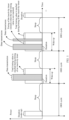
- FIG. 4a shows a relationship between the drx-HARQ RTT timerDL and the drx-retransmission timerDL.
- the drx-HARQ RTT timerDL starts timing after the terminal device sends the last symbol of a HARQ-ACK, and after the drx-HARQ RTT timerDL ends the timing, if the terminal device sends a negative acknowledgement NACK, the drx-retransmission timerDL starts timing.
- the drx-HARQ RTT timerDL, the drx-retransmission timerDL, the NACK, and a physical downlink shared channel (physical downlink shared channel, PDSCH) for retransmission scheduling in the figure all correspond to a same downlink HARQ process.
- the terminal device starts a DRX mode based on the received DRX configuration information.
- the terminal device may start the DRX mode, and then periodically wake up and sleep based on a configured DRX cycle, to reduce energy consumption. Specifically, if the terminal device determines, by using the DRX configuration information sent by the network device, that the network device configures a long DRX cycle and a short DRX cycle for the terminal device, or the network device configures only a long DRX cycle for the terminal device, the terminal device may enter the long DRX cycle; or if the terminal device determines that the network device configures only a short DRX cycle for the terminal device, the terminal device may enter the short DRX cycle. This is not limited herein.
- the terminal device After entering the long DRX cycle or the short DRX cycle, the terminal device enters a sleep state or a wake up state based on a DRX configuration, detects a PDCCH in the wake up state to ensure correct data transmission, and stops detection of the PDCCH in the sleep state to reduce power consumption and save power.
- the network device determines first DCI, where the first DCI carries first indication information and second indication information, the first indication information is used to indicate data transmission, and the second indication information is used to indicate an operation mode of an inactivity timer in DRX.
- the first DCI in this embodiment of this application may be a general reference of one type of DCI, and is not limited to a specified piece of DCI.
- This type of DCI may carry the first indication information and the second indication information.
- DCI having a same characteristic as the first DCI may be understood as the first DCI in this embodiment of this application, and the same characteristic herein may be understood as carrying the first indication information and the second indication information.
- the first indication information in this embodiment of this application is used to indicate data transmission.
- the data transmission herein includes uplink data transmission or downlink data transmission, and may further include new data transmission or data retransmission.
- the new data transmission may also be referred to as initial data transmission.
- the first indication information is used to indicate that data transmission may be new transmission or retransmission of uplink data, or may be new transmission or retransmission of downlink data.
- the first indication information is carried by using an NDI field in the first DCI.
- the first indication information indicates new data transmission; or if the NDI is not inverted, the first indication information indicates data retransmission.
- the first DCI is DCI used to indicate new data transmission or data retransmission, and the first DCI is used to schedule new data transmission or data retransmission.
- the first indication information is used to indicate data transmission may be further understood as that the first indication information is used to indicate a transmission resource required for data transmission, or may be further understood as that the first indication information is used to indicate to perform data transmission on a scheduled transmission resource.
- the network device may indicate, by using the first indication information in the first DCI, that data transmission needs to be performed, and indicates a data transmission resource that can be used when data that needs to be transmitted is being transmitted. It may be learned that the first indication information may indicate that the first DCI is DCI used to indicate data transmission.
- a format of the first DCI may be, for example, DCI in format 0_0 (format 0_0), format 0_1 (format 0_1), format 1_0 (format 1_0), format 1_1 (format 1_1), or DCI in another possible format.
- the format of the first DCI may be any one of format 0_0, format 0_1, format 1_0, and format 1_1.
- a cyclic redundancy check (cyclic redundancy check, CRC) bit of the first DCI is scrambled by a cell radio network temporary identifier (cell radio network temporary identifier, C-RNTI) or a configured scheduling radio network temporary identifier (configured scheduling RNTI, CS-RNTI).
- CRC cyclic redundancy check
- the CRC bit of the first DCI is scrambled by a C-RNTI, a CS-RNTI, or a semi-persistent channel state information-radio network temporary identifier (semi-persistent channel state information RNTI, SP-CSI-RNTI).
- DCI in the foregoing format is used to indicate uplink or downlink data scheduling
- the DCI is suitable to explicitly indicate, by using second information, whether to start or restart the inactivity timer for timing during the uplink or downlink data scheduling.
- only the foregoing DCI format corresponding to the foregoing scrambling RNTI is used to send the second indication information because these corresponding RNTIs are under control of a PDCCH detection regulation of DRX but the foregoing DCI formats scrambled by other RNTIs are not restricted by the PDCCH detection regulation of DRX, and therefore no additional field overhead is required. Therefore, DCI overheads can be reduced as much as possible by configuring the foregoing listed scrambling manner.
- the second indication information in this embodiment of this application is used to indicate the operation mode of the inactivity timer in DRX, and the inactivity timer in DRX is the drx-inactivity timer described above.
- an inactivity timer is directly used to represent the inactivity timer in DRX and the drx-inactivity timer below for related descriptions.
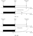
- the operation mode of the inactivity timer may be understood as a timing operation mode of the inactivity timer, a working mode of the inactivity timer, a timing mode of the inactivity timer, or the like. Regardless of the understanding manner, different operation modes of the inactivity timer may correspond to different timing operations of the timer. For ease of understanding, the following describes the operation mode of the inactivity timer with reference to FIG. 4 .
- a total length of a blank rectangular frame indicates a total timing value of the inactivity timer. It is assumed that timing starts from a left side (a position indicated by 0) of the blank rectangular frame, a timing value corresponds to timing starting is referred to as a timing start value, and a total length of a black rectangular frame indicates a timed value.
- the total timing value of the inactivity timer is also referred to as an inactivity timer value or a timing length of the inactivity timer, a time length of the inactivity timer, or a value of the inactivity timer, and the total timing value of the inactivity timer represents a maximum timing value of the inactivity timer. If the total timing value is reached during timing, timing of inactivity timer expires.
- the timed value of the inactivity timer indicates a current timed value. Generally, the timed value of the inactivity timer is less than or equal to the total timing value of the inactivity timer.
- the timing progress bar dynamically changes during timing of the inactivity timer. For example, the timing progress bar gradually increases in a direction from the timing start value to the total timing value shown in FIG.
- the timed value gradually increases as the timing progress bar increases.
- the timed value may be represented by a change in the timing progress bar.
- the total timing value of the inactivity timer is 80 ms, or in other words, the inactivity timer expires after 80ms is reached during timing, and the current timed value of the inactivity timer is 38 ms.
- the current timed value of the inactivity timer is 38 ms.
- the total timing value of the inactivity timer is still 80 ms but the current timed value is 0, it indicates that the inactivity timer does not start timing currently or is about to start timing.
- the inactivity timer may include four operation modes: starting timing, stopping (stop) timing, resetting timing, and continuing timing.
- the operation mode of the inactivity timer may include any one of starting timing, resetting timing, continuing timing, and stopping timing. The following describes several operation modes of the inactivity timer in detail.
- the operation mode of starting timing means that the inactivity timer is started to start timing.
- the inactivity timer is not in a timing state before performing a starting operation.
- the inactivity timer may be started by using the operation mode of starting timing, to trigger the inactivity timer to perform timing.
- the inactivity timer may start timing from the timing start value, or in other words, start timing from 0.
- the inactivity timer may be started in a timely manner to perform timing, thereby prolonging duration of an active state of the terminal device as much as possible, to ensure complete data transmission.
- starting of the inactivity timer may be further indicated by using DCI used to indicate data transmission.
- DCI used to indicate data transmission.
- the operation mode of stopping timing means that the inactivity timer that is performing timing stops timing, and the inactivity timer no longer performs timing after stopping timing.
- the inactivity timer is currently performing timing and the current timed value is 38 ms. If timing stops at this moment, it may be understood that timing of the inactivity timer is terminated. After timing is terminated, it directly indicates that timing of the inactivity timer expires. Still taking FIG. 4 as an example, if a timing stopping operation is performed when the current timed value is 38 ms, after timing stops, it may be considered that the timed value of the inactivity timer is directly adjusted from 38 ms to 80 ms, or in other words, timing expires.
- the inactivity timer When timing expires, the inactivity timer definitely no longer performs timing, or in other words, timing of the inactivity timer ends, so that a sleep mode can be entered in advance as soon as possible.
- the inactivity timer After timing stops, the inactivity timer retains the current timed value and no longer performs timing until another indication is received.
- the network device may advance, by using the operation mode indicating to stop, a time at which the terminal device enters an off state, to reduce device power consumption as much as possible and save power.
- the operation mode of resetting timing means that the current timed value is cleared and timing restarts from the timing start value. Still taking FIG. 4 as an example, if a timing resetting operation is performed when the current timed value is 38 ms, the timed value 38 ms needs to be cleared first, the timed value of the inactivity timer after the clearing is reset to the timing start value, namely, 0, and then timing restarts from 0. Timing restarts after the resetting, so that duration of an active state is prolonged to some extent.
- a start time of an off state is deferred as much as possible in a timing resetting manner, to ensure complete and timely data transmission.
- the operation mode of continuing timing means that timing continues on a basis of the current timed value. Still taking FIG. 4 as an example, if a timing continuing operation is performed when the current timed value is 38 ms, the inactivity timer may continue timing after the timing continuing operation is performed, and therefore a next timed value is 39 ms.
- the network device may properly and dynamically control the operation mode of the inactivity timer in the terminal device based on an amount of data that needs to be actually transmitted. In this way, data scheduling flexibility and power consumption of the terminal device can be properly balanced as much as possible, to adapt to a data transmission characteristic.
- the network device may estimate an average size of a packet that can be scheduled for transmission per time unit for uplink or downlink transmission of the terminal device, for example, B bits, and then consider that an amount of data that can be scheduled within a remaining active time of the terminal device is B ⁇ remaining active time, where the amount of data that can be scheduled may represent a capability of continuing transmitting data within the remaining time.
- the network device considers comparing the estimated amount of data that can be scheduled within the remaining active time with an amount of data in a buffer.
- the amount of data in the buffer is known to the network device.
- the amount of data in the buffer may be reported by the terminal device to the network device by using a medium access control (medium access control, MAC) control element (control element, CE) in a buffer status report (buffer status report, BSR).
- medium access control medium access control
- CE buffer status report
- the first DCI may further explicitly indicate that the operation mode of the inactivity timer in the terminal device is continuing timing, or indicate the terminal device to use a total timing value less than the remaining active time.
- the first DCI may further explicitly indicate that the operation mode of the inactivity timer in the terminal device is starting timing or resetting timing.
- the network device may further predict an amount of new arriving data in a downlink buffer or an uplink buffer in a future period of time, and compare B ⁇ remaining active time with (amount of data in the buffer + predicted amount of new arriving data), to indicate the operation mode of the inactivity timer in the terminal device or indicate the total timing value.
- the network device may dynamically indicate the operation mode of the inactivity timer in the terminal device and other parameters (for example, the total timing value and the timed value) related to the inactivity timer, so that scheduling flexibility and power consumption of the terminal device can be balanced as much as possible, and power consumption of the terminal device can be further reduced as much as possible while ensuring timely and effective data transmission.
- the inactivity timer continues performing timing until timing expires, and after performing a timing stopping operation, the inactivity timer ends timing, or in other words, no longer performs timing.
- the operation modes of the inactivity timer may be roughly classified into two types: triggering timing ending and triggering timing. It may be understood that the foregoing listed four operation modes are merely example descriptions of the operation modes of the inactivity timer. In a specific implementation process, based on guidance of the foregoing two operation modes of triggering timing ending and triggering timing, other operation modes may be further provided. This is not enumerated herein.
- the first indication information and the second indication information may be indicated by using different fields in the first DCI.
- the first indication information is indicated by using an NDI field in the first DCI
- the second indication information may be indicated by using another field different from the NDI.
- the another field herein is, for example, any other field different from the NDI field in an existing DCI format or a field formed based on a joint indication of available bits in a plurality of other fields, or the another field may be a field newly added based on an existing DCI format. Fields for carrying the first indication information and the second indication information are not limited in this embodiment of this application.
- the another field is a field newly added based on the existing DCI format
- one bit may be newly added, when a value of the newly added one bit is 1, for example, starting timing or continuing timing may be indicated; or when a value of the newly added one bit is 0, for example, resetting timing may be indicated.
- the terminal device may determine a corresponding timing manner based on a current timing status of the inactivity timer. For example, if the inactivity timer does not perform timing currently (for example, the inactivity timer is not started), a timing starting operation may be performed, or if the inactivity timer is performing timing currently, a timing continuing operation may be performed.
- the another field is a field newly added based on the existing DCI format
- two bits may be newly added, different values of the newly added two bits each may be used to correspondingly indicate one operation mode.
- 00 is used to indicate to stop timing
- 01 is used to indicate to start timing or reset timing and a timing length is a first time length
- 10 is used to indicate to start timing or reset timing and a timing length is a second time length
- 11 is used to indicate to continue timing, or an indication manner in which other different values indicate different operation modes may be further used.
- the operation mode of the inactivity timer may be jointly indicated by using one newly added bit and one bit in another existing field.
- each of four different values 00, 01, 10, and 11 formed by the newly added one bit and the existing one bit is used to correspondingly indicate one operation mode.
- a specific field to which one selected bit in the existing field belongs is not limited, as long as it is ensured that the selected existing one bit does not affect, as far as possible, an indication of information originally indicated by the field in which the existing one bit is located.
- the operation mode of the inactivity timer may be indicated based on whether a field used to carry the second indication information is inverted.
- the inversion herein is whether a value of the field changes in comparison with a value of the field in a previous piece of DCI of the first DCI, for example, whether 0 changes to 1 or whether 1 changes to 0.
- one field is newly added based on an existing DCI format, and the operation mode of the inactivity timer is indicated based on whether a value of the newly added field is the same as a value of the field in the previous piece of DCI of the first DCI.
- the operation mode that is of the inactivity timer and that is indicated by the second indication information may be continuing timing; or if the two values are different, the indicated operation mode of the inactivity timer may be starting timing or resetting timing.
- the operation mode that is of the inactivity timer and that is indicated by the second indication information may be starting timing or resetting timing; or if the two values are different, the indicated operation mode of the inactivity timer may be continuing timing.
- different operation modes may be indicated based on an inversion status of the newly added field.
- the foregoing describes some indications by using examples.
- other operation modes different from the foregoing example may be indicated during inversion, and other operation modes different from the foregoing example may also be indicated when no inversion occurs.
- an inversion interval may be set.
- the inversion interval herein refers to a quantity of pieces of DCI of which at intervals the value of the field used to carry the second indication information is inverted, or a quantity of times that a same value of the field is repeatedly transmitted in a plurality of pieces of consecutively transmitted DCI.
- values of fields that are in the plurality of pieces of DCI and that are used to carry the second indication information are successively 111000111000 in a transmission time sequence, and each value represents a value of a field that is in the first DCI and that is used to carry the second indication information. It may be learned that the value is inverted once at intervals of three pieces of DCI. Therefore, it may be considered that the inversion interval is 3. Alternatively, in another understanding manner, because the value is inverted once at intervals of three pieces of DCI, it may be considered that a quantity of times of consecutive and repeated sending is 3. In a specific implementation process, different expression manners may be used. This is not limited in this embodiment of this application.
- the inversion interval may be set to be greater than or equal to 2, for example, may be set to 2, 3, 4, or another value.
- the plurality of pieces of consecutively transmitted DCI including the first DCI and the quantity of times of consecutive and repeated sending having a same value as the field that is in the first DCI and that is used to carry the second indication information needs to be greater than or equal to a predetermined threshold, and the predetermined threshold is the specified inversion interval.
- the terminal device can still correctly determine whether second information is inverted. For example, values of fields used to carry the second indication information are successively 111000111000.
- the terminal device Because detection of a middle 0 is missed due to missed detection of a PDCCH, values received by the terminal device are successively 11100111000. However, this case does not affect determining, by the terminal device, whether the second information is inverted, and therefore timing starting or timing resetting of the inactivity timer is not affected.
- the first indication information may be carried by using the NDI field in the first DCI. Therefore, the first DCI may be used to schedule new data transmission or data retransmission.
- the operation mode that is of the inactivity timer and that is indicated by the second indication information may be continuing timing, stopping timing, or starting timing.
- the operation mode that is of the inactivity timer and that is indicated by the second indication information may be resetting timing, stopping timing, or starting timing.
- the corresponding second indication information may explicitly indicate the foregoing specific operation mode of the inactivity timer.
- flexibility of indicating a timing operation of the inactivity timer can be improved, to balance scheduling flexibility and power consumption of the terminal device as much as possible, and reduce power consumption of the terminal device as much as possible while ensuring timely and effective data transmission, so that power of the terminal device is saved and a device battery life of the terminal device is prolonged.
- a specific carrying manner may be pre-agreed by the network device and the terminal device. In this way, after receiving the first DCI sent by the network device, the terminal device may correctly interpret the first DCI, to implement same perception as the network device and ensure accurate information parsing.
- the DCI in this embodiment of this application may explicitly indicate the operation mode of the inactivity timer, unlike the current technology in which the inactivity timer is restarted to restart timing as long as the DCI used to indicate data scheduling is received.
- the operation mode of the inactivity timer is explicitly indicated in the DCI used to indicate data transmission
- an implicit indication relationship in the current technology that the DCI used to indicate data transmission definitely corresponds to restarting of the inactivity timer can be decoupled, and scheduling flexibility can be improved by using different operation modes of the inactivity timer.
- the network device may indicate, when an amount of remaining data that needs to be buffered decreases, an operation mode of continuing timing by keeping a current timing value, or may indicate, when no data needs to continue to be buffered, an operation mode of stopping timing.
- scheduling flexibility and power consumption of the terminal device can be balanced as much as possible, and power consumption of the terminal device can be reduced as much as possible while ensuring timely and effective data transmission.
- the network device sends the first DCI to the terminal device, and the terminal device may receive the first DCI sent by the network device.
- the network device may send the first DCI by using a PDCCH. Therefore, the terminal device may receive the first DCI by detecting the PDCCH. That the terminal device detects the PDCCH may actually be understood as detecting DCI sent by using the PDCCH, for example, the first DCI in this embodiment of this application.
- the network device may maintain timing of the inactivity timer in the terminal device, and therefore may know a real-time timing status of the inactivity timer in the terminal device.
- the network device may send the first DCI to the terminal device in a DRX active time of the terminal device, where the DRX active time is a process in which the terminal device is in an active state, or in other words, a time length corresponding to the active state. In this way, the terminal device can detect the first DCI, so that missed detection due to the terminal device not detecting a PDCCH can be avoided.
- the network device may further send the first DCI to the terminal device in a timing process of the drx-HARQ RTT timerDL, so that the terminal device can more quickly detect retransmission scheduling, thereby reducing a retransmission delay.
- the terminal device determines the operation mode of the inactivity timer in DRX based on an indication of the first DCI.
- the terminal device may first determine, based on the first indication information carried in the first DCI, that received DCI is DCI used to indicate data transmission, and may further determine, based on the second indication information carried in the first DCI, the operation mode that is of the inactivity timer and that is indicated by the network device.
- the terminal device controls the inactivity timer to perform a corresponding timing operation based on the operation mode indicated by the first DCI.
- the operation mode of the inactivity timer may be correspondingly adjusted based on an indication of the network device. Specifically, for example, the inactivity timer may be controlled to perform the corresponding timing operation based on the operation mode indicated by the first DCI. Because the timing operation is performed by using the operation mode indicated by the network device, a timing mode of the inactivity timer can meet an expectation of the network device as much as possible.
- the network device performs dynamic and adaptive indication based on a buffer amount of data that actually needs to be scheduled, requirements on timely data transmission and device power consumption can be met as much as possible, to dynamically balance the two as much as possible, and further reduce power consumption of the terminal device as much as possible while meeting the requirement on timely data transmission.
- the operation modes of the inactivity timer may be roughly classified into two types: triggering timing ending and triggering timing.
- the operation mode of triggering timing ending is an operation of triggering the inactivity timer to end timing
- the operation of triggering timing is an operation of triggering the inactivity timer to start or continue timing.
- the inactivity timer may be in a timing state. Once the inactivity timer starts timing, the terminal device may enter an off state only after timing of the inactivity timer expires. A very small amount of data may need to be transmitted during timing of the inactivity timer. Therefore, for the terminal device, it is unnecessary for the inactivity timer to continuously perform timing.
- the terminal device does not need to be in an active state for an excessively long time. In this case, to save power, the terminal device actually expects to enter the off state as early as possible.
- the terminal device may determine the operation mode of the inactivity timer based on an indication of the second indication information in the first DCI and determine the timing length (the foregoing total timing value) of the inactivity timer based on the DRX configuration information mentioned in S31, and then perform a corresponding timing operation based on the indicated operation mode and the timing length of the inactivity timer.
- the timing operation mode of the inactivity timer changes, but timing is still performed based on a fixed timing length that is of the inactivity timer and that is configured in advance. This may not be consistent with a current actual timing requirement.
- the network device indicates to continue timing. However, because a relatively small amount of remaining data is to be transmitted, it is expected that timing is completed as soon as possible after data transmission is completed, that is, timing expires. In the manner of continuing timing by using the fixedly configured timing length of the inactivity timer, there may be a relatively long time before timing expires. Therefore, the foregoing indication manner is only a timing manner of roughly adjusting the inactivity timer, and adjustment precision is not high.
- some explicit indications may be further performed on a timing value of the inactivity timer. For example, when a relatively small amount of data needs to be transmitted currently, the timing value of the inactivity timer may be re-indicated to shorten a time for entering the off state, so that the terminal device can enter the off state as soon as possible, thereby saving power as much as possible.
- this embodiment of this application provides two manners of adjusting the timing value of the inactivity timer. For ease of understanding, the following separately describes the two manners.
- the first DCI may further carry third indication information.
- the first DCI carries the first indication information, the second indication information, and the third indication information.
- the first indication information and the second indication information have been described above.
- the third indication information is used to indicate the total timing value of the inactivity timer, that is, the third indication information indicates an inactivity timer value of the inactivity timer.
- the third indication information may be used to explicitly indicate that the total timing value of the inactivity timer needs to be adjusted, and also indicate a total timing value to be adjusted to.
- the total timing value indicated by the third indication information may be represented by a quantity of time units described above.
- the network device may configure one or more total timing values for the terminal device. If only one total timing value is configured, the inactivity timer may always use the total timing value to perform timing. In other words, the total timing value of the inactivity timer does not change during use of the inactivity timer.
- the network device may indicate the configured total timing value in an implicit indication manner by using the first DCI.
- the implicit indication manner herein means that the total timing value is not directly explicitly indicated.
- the first DCI carries only the first indication information and the second indication information.
- the terminal device determines that the total timing value of the inactivity timer is a total timing value preconfigured by the network device. If a plurality of total timing values are configured, the network device may explicitly indicate the total timing value by using the third indication information.
- the current timed value and the total timing value of the inactivity timer are 38 ms and 80 ms
- the operation mode that is of the inactivity timer and that is indicated by the second indication information carried in the first DCI is continuing timing
- the total timing value explicitly indicated by the third indication information carried in the first DCI is 60 ms.
- the terminal device continues timing on the basis of the current timed value 38 ms, that is, a next timing moment is 39 ms
- the total timing value of the inactivity timer is adjusted from earlier 80 ms to 60 ms.
- FIG. 6A is a schematic timing diagram of the inactivity timer before adjustment
- a lower part of FIG. 6A is a schematic timing diagram of the inactivity timer after adjustment is performed based on an indication of the first DCI.
- the total timing value of the inactivity time is reduced from 80 ms to 60 ms after the adjustment. Through the adjustment, a time length of reaching the off state is shortened. In this way, the terminal device can enter the off state as soon as possible, thereby reducing device power consumption.
- the total timing value of the inactivity timer may be adjusted to be larger in some cases.
- the total timing value that is of the inactivity timer and that is indicated by the third indication information may be less than or greater than a current total timing value of the inactivity timer.
- whether the total timing value is adjusted to be larger or smaller may be determined by the network device based on an actual amount of data that needs to be currently transmitted, so that adjustment flexibility can be improved.
- a total timing value to be adjusted to that is of the inactivity timer and that is indicated by the third indication information is 33 ms, and is less than the current timed value 38 ms of the inactivity timer.
- the terminal device may consider that timing of the inactivity timer expires.
- the network device and the terminal device may pre-agree to consider such logic error as expiration of timing of the timer. In this way, normal use of the inactivity timer is not affected as much as possible.
- a system is tolerant of a logic indication error shown in FIG. 6B .
- the terminal device may consider, based on the pre-agreement, that timing of the inactivity timer expires, and then enter the off state. In this manner, a fault tolerance capability of the system can be improved, and system reliability is improved.
- the total timing value indicated by the third indication information is less than or equal to the timed value of the inactivity timer should be understood as an incorrect indication because such an indication is illogical.
- this is understood as an incorrect logic indication, abnormal running of the inactivity timer may be caused. Therefore, in this solution, when the foregoing incorrect logic indication appears, it may be understood that timing of the inactivity timer expires, and a system may tolerate the foregoing incorrect logic indication. In this way, a fault tolerance capability of the system can be improved, and normal running of the inactivity timer can be further ensured, thereby improving reliability and stability of the system.
- the total timing value indicated by the third indication information may be the same as the current total timing value of the inactivity timer. In this case, the terminal device may no longer need to adjust the total timing value of the inactivity timer.
- the second indication information and the third indication information may be separately indicated by using different fields in the first DCI.
- both the second indication information and the third indication information may be jointly indicated by using different fields, and fields for joint indication of the second indication information and the third indication information may be the same or may be different.
- the joint indication herein may be understood as indication performed by using values represented by combining bits in different fields.
- the second indication information and the third indication information may be indicated by using a value of a same field in the first DCI, or in other words, the second indication information and the third indication information may be indicated by using one value of one field.
- the second indication information and the third indication information may be separately indicated by using different bits in a same field in the first DCI, or the like.
- fields used to indicate the second indication information and the third indication information may reuse some existing fields in the existing DCI format, or may be some fields newly added on the basis of the existing DCI format. This is not limited in this embodiment of this application.
- This embodiment of this application provides a plurality of manners of indicating the second indication information and the third indication information, to improve indication flexibility, and flexibly use a field and a bit in the first DCI based on an actual situation, thereby enhancing applicability of the solution.
- the first DCI may further carry fourth indication information.
- the first DCI carries the first indication information, the second indication information, and the fourth indication information.
- the first indication information and the second indication information have been described above, and the fourth indication information is used to indicate the timed value of the inactivity timer.
- the fourth indication information may be used to explicitly indicate that the timed value of the inactivity timer needs to be adjusted, and indicate a timed value to be adjusted to.
- the timed value indicated by the fourth indication information may be represented by a quantity of time units described above.
- the network device may configure a plurality of timed values for the terminal device, and explicitly indicate, by using the fourth indication information, the timed value that is of the inactivity timer and that currently needs to be adjusted.
- the timed value indicated by the fourth indication information may be a quantity of time units described above, for example, 30 ms.
- the timed value indicated by the fourth indication information may be a timed proportion value, and the timed proportion value is used to indicate a proportion of the total timing value of the inactivity timer.
- the timed proportion value is 60%, 1/3, or 0.7.
- the timed value calculated in the calculation manner may not be an integer, an integral timed value may be obtained through rounding up or down.
- the current timed value and the total timing value of the inactivity timer are 38 ms and 80 ms
- the operation mode that is of the inactivity timer and that is indicated by the second indication information carried in the first DCI is continuing timing
- the timed value explicitly indicated by the fourth indication information carried in the first DCI is 68 ms.
- the terminal device adjusts the current timed value from 38 ms to 68 ms, and then continues timing from 68 ms. After the adjustment, a time length of reaching the off state is shortened, so that the terminal device can enter the off state as soon as possible, thereby reducing device power consumption.
- the timed value of the inactivity timer may be adjusted to be smaller in some cases.
- the total timing value that is of the inactivity timer and that is indicated by the fourth indication information may be greater than or less than the current timed value of the inactivity timer.
- whether the timed value is adjusted to be larger or smaller may be determined by the network device based on an actual amount of data that needs to be currently transmitted, so that adjustment flexibility can be improved.
- timed value 84 ms that is of the inactivity timer and that is indicated by the fourth indication information when the timed value 84 ms that is of the inactivity timer and that is indicated by the fourth indication information is greater than the total timing value 80 ms of the inactivity timer, it indicates that timing of the inactivity timer expires.
- the timed value indicated by the fourth indication information is greater than or equal to the total timing value of the inactivity timer should be understood as an incorrect indication because such an indication is illogical. However, if this is understood as an incorrect logic indication, abnormal running of the inactivity timer may be caused.
- the total timing value indicated by the fourth indication information may be the same as the current timed value of the inactivity timer. In this case, the terminal device may no longer need to adjust the timed value of the inactivity timer.
- the second indication information and the fourth indication information may be separately indicated by using different fields in the first DCI.
- both the second indication information and the fourth indication information may be jointly indicated by using different fields, and fields for joint indication of the second indication information and the fourth indication information may be the same or may be different.
- the joint indication herein may be understood as indication performed by using values represented by combining bits in different fields.
- the second indication information and the fourth indication may be indicated by using a value of a same field in the first DCI, or in other words, the second indication information and the fourth indication information may be indicated by using one value of one field.
- the second indication information and the fourth indication information may be separately indicated by using different bits in a same field in the first DCI, or the like.
- fields used to indicate the second indication information and the fourth indication information may reuse some existing fields in the existing DCI format, or may be some fields newly added on the basis of the existing DCI format. This is not limited in this embodiment of this application.
- This embodiment of this application provides a plurality of manners of indicating the second indication information and the fourth indication information, to improve indication flexibility, and flexibly use a field and a bit in the first DCI based on an actual situation.
- the first DCI may alternatively carry the first indication information, the second indication information, the third indication information, and the fourth indication information.
- the current timed value and the total timing value of the inactivity timer are 38 ms and 80 ms
- the operation mode that is of the inactivity timer and that is indicated by the second indication information carried in the first DCI is continuing timing
- the total timing value explicitly indicated by the third indication information carried in the first DCI is 60 ms
- the timed value explicitly indicated by the fourth indication information carried in the first DCI is 49 ms
- FIG. 8 is merely an example in which four types of indication information: the first indication information, the second indication information, the third indication information, and the fourth indication information are combined for indication.
- the network device may dynamically perform different indications based on an amount of data that needs to be transmitted. Details are not described herein.
- the first DCI in this embodiment of this application may be transmitted in an associated search space.
- the first DCI may be in any one of format 0_0, format 0_1, format 1_0, and format 1_1, and DCI in these different formats are associated by corresponding search spaces. Therefore, DCI in corresponding formats may be searched in these associated search spaces.
- a configuration message for configuring the associated search space may carry at least one of the second indication information, the third indication information, or the fourth indication information. Because the second indication information, the third indication information, or the fourth indication information is indication information used to indicate that the first DCI in this application is different from existing DCI.
- the second indication information, the third indication information, and the fourth indication information may be used to explicitly indicate some information related to timing of the inactivity timer, and some new indication functions are added in comparison with the existing DCI. Therefore, when the first DCI is being interpreted, the first DCI needs to be interpreted in a new interpretation manner.
- the network device may notify, by using an RRC configuration message, the terminal device that the new interpretation manner in this embodiment of this application needs to be used to interpret subsequently received first DCI.
- the network device may notify, by using the RRC configuration message, the terminal device that the first DCI is DCI that can indicate at least one of the operation mode of the inactivity timer (indicated by using the second indication information), the total timing value of the inactivity timer (indicated by using the third indication information), and the timed value of the inactivity timer (indicated by using the fourth indication information). Further, the terminal device may implement perception unification with the network device based on the RRC configuration message, to ensure accurate information exchange between the terminal and the network.
- whether DCI has the foregoing new indication function may be directly indicated to the terminal device based on a type of a search space. Specifically, if a search space associated with a specified piece of DCI is a user equipment-specific search space (UE-specific search space, USS), that is, if the DCI is transmitted in the USS, it indicates that the DCI has the foregoing new indication function. In this case, the DCI carries at least one of the second indication information, the third indication information, and the fourth indication information.
- UE-specific search space UE-specific search space
- a search space associated with a specified piece of DCI is a common search space (common search space, CSS), that is, if the DCI is transmitted in the CSS, it indicates that the DCI does not have the foregoing new indication function, and may be DCI in a current technology. In this case, the DCI does not carry any one of the second indication information, the third indication information, and the fourth indication information. Because the first DCI in this embodiment of this application is DCI with the foregoing new function, based on the technical solution, the first DCI is transmitted in the USS, but is not transmitted in the CSS. In a manner of indicating, by using the type of the search space, whether transmitted DCI has the foregoing new function, signaling overheads of DCI that is transmitted in a CSS-type search space and that does not require the foregoing new function can be reduced.
- common search space common search space
- an embodiment of this application provides a communications apparatus 900.
- the communications apparatus 900 may be a terminal device, and can implement functions of the terminal device in the information transmission method provided in the embodiments of this application; or the communications apparatus 900 may be an apparatus that can support the terminal device in implementing functions of the terminal device in the information transmission method provided in the embodiments of this application.
- the communications apparatus 900 may be a hardware structure, a software module, or a hardware structure and a software module.
- the communications apparatus 900 may be implemented by a chip system. In this embodiment of this application, the chip system may include a chip, or may include a chip and another discrete device. As shown in FIG.
- the communications apparatus 900 may include a processing module 901, a receiving module 902, and a sending module 903.
- the sending module 903 may not be a mandatory module, and therefore is represented by dashed lines in FIG. 9 .
- the receiving module 902 and the sending module 903 are used by the communications apparatus 900 to communicate with another module, and may be a circuit, a device, an interface, a bus, a software module, a transceiver, or any other apparatus that can implement communication.
- the processing module 901 may be configured to perform S32, S35, and S36 in the embodiment shown in FIG. 3 , and/or configured to support another process of the technology described in this specification.
- the receiving module 902 may be configured to perform S34 in the embodiment shown in FIG. 3 , and/or configured to support another process of the technology described in this specification.
- the receiving module 902 and the sending module 903 may perform a corresponding communication function under control of the processing module 901.
- the receiving module 902 may receive first DCI sent by a network device, where the first DCI carries first indication information and second indication information, the first indication information is used to indicate data transmission, and the second indication information is used to indicate an operation mode of an inactivity timer in DRX.
- the processing module 901 may determine the operation mode of the inactivity timer based on an indication of the first DCI. In a possible implementation, the processor 901 may further control the inactivity timer to perform a corresponding timing operation based on the operation mode indicated by the first DCI.
- the receiving module 902 and the sending module 903 may be separately disposed, or in other words, are two independent function modules in this case.
- the receiving module 902 and the sending module 903 may be disposed as one function module in an integrated manner, for example, disposed as one transceiver module.
- the transceiver module has a capability of the receiving module 902 to receive information, and also has a capability of the sending module 903 to send information.
- an embodiment of this application provides a communications apparatus 1000.
- the communications apparatus 1000 may be a network device, and can implement functions of the network device in the information transmission method provided in the embodiments of this application; or the communications apparatus 1000 may be an apparatus that can support the network device in implementing functions of the network device in the information transmission method provided in the embodiments of this application.
- the communications apparatus 1000 may be a hardware structure, a software module, or a hardware structure and a software module.
- the communications apparatus 1000 may be implemented by a chip system. In this embodiment of this application, the chip system may include a chip, or may include a chip and another discrete device. As shown in FIG.
- the communications apparatus 1000 may include a processing module 1001, a sending module 1002, and a receiving module 1003.
- the receiving module 1003 may not be a mandatory module, and therefore is represented by dashed lines in FIG. 10 .
- the sending module 1002 and the receiving module 1003 are used by the communications apparatus 1000 to communicate with another module, and may be a circuit, a device, an interface, a bus, a software module, a transceiver, or any other apparatus that can implement communication.
- the processing module 1001 may be configured to perform S33 in the embodiment shown in FIG. 3 , and/or configured to support another process of the technology described in this specification.
- the sending module 1002 may be configured to perform S31 and S34 in the embodiment shown in FIG. 3 , and/or configured to support another process of the technology described in this specification.
- the sending module 1002 and the receiving module 1003 may perform a corresponding communication function under control of the processing module 1001.
- the processing module 1001 may determine first DCI, where the first DCI carries first indication information and second indication information, the first indication information is used to indicate data transmission, and the second indication information is used to indicate an operation mode of an inactivity timer.
- the sending module 1002 may send the first DCI to a terminal device.
- the sending module 1002 and the receiving module 1003 may be separately disposed, or in other words, are two independent function modules in this case.
- the sending module 1002 and the receiving module 1003 may be disposed as one function module in an integrated manner, for example, disposed as one transceiver module.
- the transceiver module has a capability of the receiving module 1003 to receive information, and also has a capability of the sending module 1002 to send information.
- Module division in this embodiment of this application is an example, is merely logical function division, and may be another division in actual implementation.
- function modules in the embodiments of this application may be integrated in one processor, or each of the modules may exist alone physically, or two or more modules are integrated in one module.
- the integrated module may be implemented in a form of hardware, or may be implemented in a form of a software function module.
- FIG. 11 is a schematic structural diagram of the communications apparatus 1100 provided in this embodiment of this application.
- the communications apparatus 1100 may be a terminal device, and can implement functions of the terminal device in the information transmission method provided in the embodiments of this application; or the communications apparatus 1100 may be an apparatus that can support a terminal device in implementing functions of the terminal device in the information transmission method provided in the embodiments of this application.
- the communications apparatus 1100 may be a chip system. In this embodiment of this application, the chip system may include a chip, or may include a chip and another discrete device.
- the communications apparatus 1100 includes at least one processor 1101, configured to implement or support the apparatus in implementing functions of the terminal device in the information transmission method provided in the embodiments of this application.
- the communications apparatus 1100 may further include at least one memory 1102, configured to store program instructions and/or data.
- the memory 1102 is coupled to the processor 1101.
- the coupling in this embodiment of this application is an indirect coupling or a communication connection between apparatuses, units, or modules, may be implemented in electrical, mechanical, or another form, and is used for information exchange between the apparatuses, the units, or the modules.
- the processor 1101 may operate in cooperation with the memory 1102.
- the processor 1101 may execute the program instructions stored in the memory 1102. At least one of the at least one memory may be included in the processor.
- the communications apparatus 1100 may further include a transceiver 1103, configured to communicate with another device by using a transmission medium, so that the communications apparatus 1100 can communicate with the another device.
- the processor 1101 may use the transceiver 1103 to receive and send data.
- the transceiver 1103 may correspond to the receiving module 902 and the sending module 903 in FIG. 9 .
- the transceiver 1103 may be specifically some communications interfaces.
- a specific connection medium between the transceiver 1103, the processor 1101, and the memory 1102 is not limited.
- the memory 1102, the processor 1101, and the transceiver 1103 are connected through a bus 1104 in FIG. 11 .
- the bus is represented by using a bold line in FIG. 11 .
- a manner of connection between other components is merely an example for description, and imposes no limitation.
- the bus may be classified into an address bus, a data bus, a control bus, and the like. For ease of representation, only one thick line is used to represent the bus in FIG. 11 , but this does not mean that there is only one bus or only one type of bus.
- FIG. 12 is a schematic structural diagram of the communications apparatus 1200 provided in this embodiment of this application.
- the communications apparatus 1200 may be a network device, and can implement functions of the network device in the information transmission method provided in the embodiments of this application; or the communications apparatus 1200 may be an apparatus that can support a network device in implementing functions of the network device in the information transmission method provided in the embodiments of this application.
- the communications apparatus 1200 may be a chip system. In this embodiment of this application, the chip system may include a chip, or may include a chip and another discrete device.
- the communications apparatus 1200 includes at least one processor 1201, configured to implement or support the apparatus in implementing functions of the network device in the information transmission method provided in the embodiments of this application.
- the communications apparatus 1200 may further include at least one memory 1202, configured to store program instructions and/or data.
- the memory 1202 is coupled to the processor 1201.
- the coupling in this embodiment of this application is an indirect coupling or a communication connection between apparatuses, units, or modules, may be implemented in electrical, mechanical, or another form, and is used for information exchange between the apparatuses, the units, or the modules.
- the processor 1201 may operate in cooperation with the memory 1202.
- the processor 1201 may execute the program instructions stored in the memory 1202. At least one of the at least one memory may be included in the processor.
- the communications apparatus 1200 may further include a transceiver 1203, configured to communicate with another device by using a transmission medium, so that the communications apparatus 1200 can communicate with the another device.
- the processor 1201 may use the transceiver 1203 to receive and send data.
- the transceiver 1203 may correspond to the sending module 1002 and the receiving module 1003 in FIG. 10 .
- the transceiver 1203 may be specifically some communications interfaces.
- a specific connection medium between the transceiver 1203, the processor 1201, and the memory 1202 is not limited.
- the memory 1202, the processor 1201, and the transceiver 1203 are connected through a bus 1204 in FIG. 12 .
- the bus is represented by using a bold line in FIG. 12 .
- a manner of connection between other components is merely an example for description, and imposes no limitation.
- the bus may be classified into an address bus, a data bus, a control bus, and the like. For ease of representation, only one thick line is used to represent the bus in FIG. 12 , but this does not mean that there is only one bus or only one type of bus.
- the processor 1101 and the processor 1201 may be general purpose processors, digital signal processors, application-specific integrated circuits, field programmable gate arrays or other programmable logic devices, discrete gates or transistor logic devices, or discrete hardware components, and may implement or execute the methods, steps, and logical block diagrams disclosed in the embodiments of this application.
- the general purpose processor may be a microprocessor or any conventional processor or the like. The steps of the method disclosed with reference to the embodiments of this application may be directly performed and completed by a hardware processor, or may be performed and completed by a combination of hardware and a software module in the processor.
- the memory 1102 and the memory 1202 each may be a non-volatile memory such as an HDD or a solid state drive SSD, or may be a volatile memory (volatile memory) such as a random access memory RAM.
- the memory is any other medium that can carry or store expected program code in a form of an instruction or a data structure and that can be accessed by a computer, but is not limited thereto.
- the memory in the embodiments of this application may be alternatively a circuit or any other apparatus that can implement a storage function, and is configured to store program instructions and/or data.
- An aspect of this application further provides a computer-readable storage medium.
- the computer-readable storage medium includes computer instructions. When the computer instructions are run on a computer, the computer is enabled to perform the information transmission method in the embodiments of this application.
- An aspect of this application further provides a chip system.
- the chip system includes a processor, and may further include a memory, configured to implement the information transmission method in the embodiments of this application.
- the chip system may include a chip, or may include a chip and another discrete device.
- An aspect of this application further provides a communications system.
- the communications system includes the communications apparatus 900 in FIG. 9 and the communications apparatus 1000 in FIG. 10 .
- An aspect of this application further provides another communications system.
- the communications system includes the communications apparatus 1100 in FIG. 11 and the communications apparatus 1200 in FIG. 12 .
- An embodiment of this application further provides a computer program product including instructions.
- the computer program product stores the instructions, and when the instructions are run on a computer, the computer is enabled to perform the information transmission method in the embodiments of this application.
Landscapes
- Engineering & Computer Science (AREA)
- Computer Networks & Wireless Communication (AREA)
- Signal Processing (AREA)
- Mobile Radio Communication Systems (AREA)
Claims (15)
- Informationsübertragungsverfahren, wobei das Verfahren umfasst:Empfangen (S34), durch ein Endgerät, erster Downlink-Steuerinformationen (DCI), die durch eine Netzwerkvorrichtung gesendet werden, wobei die ersten DCI erste Anzeigeinformationen und zweite Anzeigeinformationen tragen, wobei die ersten Anzeigeinformationen verwendet werden, um eine Datenübertragung anzuzeigen, und die zweiten Anzeigeinformationen verwendet werden, um einen Betriebsmodus eines Inaktivitätszeitgebers bei diskontinuierlichem Empfang (DRX) anzuzeigen; undBestimmen (S35), durch das Endgerät, des Betriebsmodus des Inaktivitätszeitgebers basierend auf einer Anzeige der ersten DCI;wobei der Betriebsmodus des Inaktivitätszeitgebers eines der Folgenden umfasst: ein Starten einer Zeiteinstellung, ein Stoppen einer Zeiteinstellung, ein Zurücksetzen einer Zeiteinstellung und ein Fortsetzen einer Zeiteinstellung;wobei die zweiten Anzeigeinformationen in den ersten DCI explizit angezeigt werden und die ersten DCI verwendet werden, um eine neue Datenübertragung oder erneute Datenübertragung zu planen; und ein neues Datenanzeige(NDI)-Feld in den ersten DCI die ersten Anzeigeinformationen trägt und ein Feld in den ersten DCI, das sich von dem NDI-Feld unterscheidet, die zweiten Anzeigeinformationen trägt.
- Verfahren nach Anspruch 1, wobeiwenn die ersten DCI verwendet werden, um eine neue Datenübertragung zu planen, die zweiten Anzeigeinformationen anzeigen, dass der Betriebsmodus des Inaktivitätszeitgebers ein Fortsetzen einer Zeiteinstellung, ein Stoppen einer Zeiteinstellung oder ein Starten einer Zeiteinstellung ist; oderwenn die ersten DCI verwendet werden, um eine erneute Datenübertragung zu planen, die zweiten Anzeigeinformationen verwendet werden, um anzuzeigen, dass der Betriebsmodus ein Zurücksetzen einer Zeiteinstellung, ein Stoppen einer Zeiteinstellung oder ein Starten einer Zeiteinstellung ist.
- Verfahren nach Anspruch 1 oder 2, wobei die ersten DCI ferner dritte Anzeigeinformationen tragen, die dritten Anzeigeinformationen verwendet werden, um einen Gesamtzeiteinstellungswert des Inaktivitätszeitgebers anzuzeigen, und der Gesamtzeiteinstellungswert, der durch die dritten Anzeigeinformationen angezeigt wird, einer von einer Vielzahl von Gesamtzeiteinstellungswerten ist, die durch die Netzwerkvorrichtung für das Endgerät konfiguriert werden.
- Verfahren nach einem der Ansprüche 1 bis 3, wobei die ersten DCI ferner vierte Anzeigeinformationen tragen und die vierten Anzeigeinformationen verwendet werden, um einen zeitlich festgelegten Wert des Inaktivitätszeitgebers anzuzeigen.
- Verfahren nach einem der Ansprüche 1 bis 4, wobei die zweiten Anzeigeinformationen für eine Anzeige verwendet werden, die darauf basiert, ob ein Wert eines Feldes in den ersten DCI gleich einem Wert des Feldes in einem vorhergehenden Teil von DCI der ersten DCI ist; undfalls die Werte gleich sind, die zweiten Anzeigeinformationen anzeigen, dass der Betriebsmodus des Inaktivitätszeitgebers ein Stoppen einer Zeiteinstellung oder ein Fortsetzen einer Zeiteinstellung ist, und falls die Werte unterschiedlich sind, die zweiten Anzeigeinformationen anzeigen, dass der Betriebsmodus des Inaktivitätszeitgebers ein Starten einer Zeiteinstellung oder ein Zurücksetzen einer Zeiteinstellung ist; oderfalls die Werte gleich sind, die zweiten Anzeigeinformationen anzeigen, dass der Betriebsmodus des Inaktivitätszeitgebers ein Starten einer Zeiteinstellung oder ein Fortsetzen einer Zeiteinstellung ist, und falls die Werte unterschiedlich sind, die zweiten Anzeigeinformationen anzeigen, dass der Betriebsmodus des Inaktivitätszeitgebers ein Stoppen einer Zeiteinstellung oder ein Fortsetzen einer Zeiteinstellung ist.
- Verfahren nach Anspruch 5, wobei für eine Vielzahl von Teilen von kontinuierlich übertragenen DCI, umfassend die ersten DCI, eine Anzahl von Malen eines aufeinanderfolgenden und wiederholten Sendens, die denselben Wert wie das Feld in den ersten DCI aufweisen, größer als oder gleich einem zuvor bestimmten Schwellenwert ist und der zuvor bestimmte Schwellenwert eine ganze Zahl größer als oder gleich 2 ist.
- Informationsübertragungsverfahren, wobei das Verfahren umfasst:Bestimmen (S33), durch eine Netzwerkvorrichtung, von ersten Downlink-Steuerinformationen (DCI), wobei die ersten DCI erste Anzeigeinformationen und zweite Anzeigeinformationen tragen, wobei die ersten Anzeigeinformationen verwendet werden, um eine Datenübertragung anzuzeigen, und die zweiten Anzeigeinformationen verwendet werden, um einen Betriebsmodus eines Inaktivitätszeitgebers bei diskontinuierlichem Empfang (DRX) anzuzeigen; undSenden (S34), durch die Netzwerkvorrichtung, der ersten DCI an ein Endgerät:wobei der Betriebsmodus des Inaktivitätszeitgebers eines der Folgenden umfasst: ein Starten einer Zeiteinstellung, ein Stoppen einer Zeiteinstellung, ein Zurücksetzen einer Zeiteinstellung und ein Fortsetzen einer Zeiteinstellung;wobei die zweiten Anzeigeinformationen in den ersten DCI explizit angezeigt werden und die ersten DCI verwendet werden, um eine neue Datenübertragung oder erneute Datenübertragung zu planen; und ein neues Datenanzeige(NDI)-Feld in den ersten DCI die ersten Anzeigeinformationen trägt und ein Feld in den ersten DCI, das sich von dem NDI-Feld unterscheidet, die zweiten Anzeigeinformationen trägt.
- Verfahren nach Anspruch 7, wobeiwenn die ersten DCI verwendet werden, um eine neue Datenübertragung zu planen, die zweiten Anzeigeinformationen anzeigen, dass der Betriebsmodus des Inaktivitätszeitgebers ein Fortsetzen einer Zeiteinstellung, ein Stoppen einer Zeiteinstellung oder ein Starten einer Zeiteinstellung ist; oderwenn die ersten DCI verwendet werden, um eine erneute Datenübertragung zu planen, die zweiten Anzeigeinformationen verwendet werden, um anzuzeigen, dass der Betriebsmodus ein Zurücksetzen einer Zeiteinstellung, ein Stoppen einer Zeiteinstellung oder ein Starten einer Zeiteinstellung ist.
- Verfahren nach Anspruch 7 oder 8, wobei die ersten DCI ferner dritte Anzeigeinformationen tragen, die dritten Anzeigeinformationen verwendet werden, um einen Gesamtzeiteinstellungswert des Inaktivitätszeitgebers anzuzeigen, und der Gesamtzeiteinstellungswert, der durch die dritten Anzeigeinformationen angezeigt wird, einer von einer Vielzahl von Gesamtzeiteinstellungswerten ist, die durch die Netzwerkvorrichtung für das Endgerät konfiguriert werden.
- Verfahren nach einem der Ansprüche 7 bis 9, wobei die ersten DCI ferner vierte Anzeigeinformationen tragen und die vierten Anzeigeinformationen verwendet werden, um einen zeitlich festgelegten Wert des Inaktivitätszeitgebers anzuzeigen.
- Verfahren nach einem der Ansprüche 7 bis 10, wobei die zweiten Anzeigeinformationen für eine Anzeige verwendet werden, die darauf basiert, ob ein Wert eines Feldes in den ersten DCI gleich einem Wert des Feldes in einem vorherigen Teil von DCI der ersten DCI ist; undfalls die Werte gleich sind, die zweiten Anzeigeinformationen anzeigen, dass der Betriebsmodus des Inaktivitätszeitgebers ein Stoppen einer Zeiteinstellung oder ein Fortsetzen einer Zeiteinstellung ist, und falls die Werte unterschiedlich sind, die zweiten Anzeigeinformationen anzeigen, dass der Betriebsmodus des Inaktivitätszeitgebers ein Starten einer Zeiteinstellung oder ein Zurücksetzen einer Zeiteinstellung ist; oderfalls die Werte gleich sind, die zweiten Anzeigeinformationen anzeigen, dass der Betriebsmodus des Inaktivitätszeitgebers ein Starten einer Zeiteinstellung oder ein Fortsetzen einer Zeiteinstellung ist, und falls die Werte unterschiedlich sind, die zweiten Anzeigeinformationen anzeigen, dass der Betriebsmodus des Inaktivitätszeitgebers ein Stoppen einer Zeiteinstellung oder ein Fortsetzen einer Zeiteinstellung ist.
- Kommunikationseinrichtung, die konfiguriert ist, um das Verfahren nach einem der Ansprüche 1 bis 6 durchzuführen.
- Kommunikationseinrichtung, die konfiguriert ist, um das Verfahren nach einem der Ansprüche 7 bis 11 durchzuführen.
- Computerprogramm, umfassend Anweisungen, die, wenn sie durch einen Computer ausgeführt werden, den Computer veranlassen, das Verfahren nach einem der Ansprüche 1 bis 6 auszuführen.
- Computerprogramm, umfassend Anweisungen, die, wenn sie durch einen Computer ausgeführt werden, den Computer veranlassen, das Verfahren nach einem der Ansprüche 7 bis 11 auszuführen.
Applications Claiming Priority (3)
| Application Number | Priority Date | Filing Date | Title |
|---|---|---|---|
| CN201811302951 | 2018-11-02 | ||
| CN201910028472.0A CN111148193B (zh) | 2018-11-02 | 2019-01-11 | 一种信息传输方法及通信装置 |
| PCT/CN2019/115161 WO2020088680A1 (zh) | 2018-11-02 | 2019-11-01 | 一种信息传输方法及通信装置 |
Publications (3)
| Publication Number | Publication Date |
|---|---|
| EP3869874A1 EP3869874A1 (de) | 2021-08-25 |
| EP3869874A4 EP3869874A4 (de) | 2021-12-29 |
| EP3869874B1 true EP3869874B1 (de) | 2023-04-26 |
Family
ID=70516573
Family Applications (1)
| Application Number | Title | Priority Date | Filing Date |
|---|---|---|---|
| EP19878854.9A Active EP3869874B1 (de) | 2018-11-02 | 2019-11-01 | Informationsübertragungsverfahren und kommunikationsvorrichtung |
Country Status (3)
| Country | Link |
|---|---|
| US (1) | US11991708B2 (de) |
| EP (1) | EP3869874B1 (de) |
| CN (1) | CN111148193B (de) |
Families Citing this family (9)
| Publication number | Priority date | Publication date | Assignee | Title |
|---|---|---|---|---|
| CN111148193B (zh) * | 2018-11-02 | 2021-09-07 | 华为技术有限公司 | 一种信息传输方法及通信装置 |
| US12052109B2 (en) * | 2019-08-06 | 2024-07-30 | Nokia Technologies Oy | Retransmission mechanism for configured grant uplink transmission |
| CN111092692A (zh) * | 2019-11-08 | 2020-05-01 | 中兴通讯股份有限公司 | 一种控制信息指示方法、通信节点及计算机可读存储介质 |
| US11659597B2 (en) * | 2019-11-29 | 2023-05-23 | FG Innovation Company Limited | User equipment and method for two-step random access procedure |
| WO2022029117A1 (en) * | 2020-08-06 | 2022-02-10 | Telefonaktiebolaget Lm Ericsson (Publ) | Control of inactivity timer triggering for nr ue |
| CN114080068A (zh) * | 2020-08-20 | 2022-02-22 | 维沃移动通信有限公司 | 非连续接收drx配置方法、装置和设备 |
| JP7646820B2 (ja) * | 2020-09-28 | 2025-03-17 | 華為技術有限公司 | 通信方法、装置、およびシステム |
| US11825415B2 (en) * | 2021-08-11 | 2023-11-21 | Qualcomm Incorporated | Power savings for voice services |
| CN116321533A (zh) * | 2021-12-21 | 2023-06-23 | 大唐移动通信设备有限公司 | 一种通信方法及终端 |
Family Cites Families (20)
| Publication number | Priority date | Publication date | Assignee | Title |
|---|---|---|---|---|
| US9504083B2 (en) * | 2008-01-10 | 2016-11-22 | Innovative Sonic Limited | Method and related communications device for improving discontinuous reception functionality |
| CN101965037B (zh) * | 2009-07-22 | 2013-01-30 | 电信科学技术研究院 | 一种非连续接收处理方法及设备 |
| CN105722195B (zh) * | 2011-01-28 | 2019-12-24 | 华为技术有限公司 | 一种非连续接收的方法和装置 |
| CN102625432B (zh) * | 2011-01-28 | 2016-01-27 | 华为技术有限公司 | 一种非连续接收的方法和装置 |
| US8972762B2 (en) * | 2012-07-11 | 2015-03-03 | Blackberry Limited | Computing devices and methods for resetting inactivity timers on computing devices |
| CN104782218B (zh) * | 2012-11-16 | 2017-12-19 | 诺基亚技术有限公司 | 用于不同流量的不连续接收(drx)的方法和设备 |
| WO2014109769A1 (en) * | 2013-01-14 | 2014-07-17 | Nokia Corporation | Improved handling of control signaling |
| CN106034318B (zh) * | 2015-03-16 | 2019-10-29 | 中国移动通信集团公司 | 一种非连续接收的控制方法和装置 |
| JP2019054310A (ja) | 2016-01-29 | 2019-04-04 | シャープ株式会社 | 端末装置、通信方法、および、集積回路 |
| WO2017188794A1 (en) | 2016-04-28 | 2017-11-02 | Samsung Electronics Co., Ltd. | Methods and systems for configuring timers in lte networks |
| KR101971780B1 (ko) * | 2016-08-11 | 2019-04-26 | 주식회사 케이티 | 멀티캐스트 데이터를 수신하는 방법 및 그 장치 |
| CN108307547A (zh) | 2016-09-30 | 2018-07-20 | 中兴通讯股份有限公司 | 一种确定非连续接收配置信息的方法及装置 |
| CN108616969B (zh) * | 2016-12-20 | 2020-07-21 | 华为技术有限公司 | 数据发送方法、数据接收方法及设备 |
| CN114900858A (zh) * | 2016-12-30 | 2022-08-12 | 英特尔公司 | 用于无线电通信的方法和设备 |
| US11019544B2 (en) * | 2017-02-02 | 2021-05-25 | Samsung Electronics Co., Ltd. | Method and apparatus for transmitting and receiving data in mobile communication system |
| JP2019087964A (ja) * | 2017-11-10 | 2019-06-06 | シャープ株式会社 | 端末装置、基地局装置、および、通信方法 |
| WO2019136205A1 (en) * | 2018-01-04 | 2019-07-11 | Ofinno, Llc | Semi-persistent channel state information report |
| WO2020088680A1 (zh) * | 2018-11-02 | 2020-05-07 | 华为技术有限公司 | 一种信息传输方法及通信装置 |
| CN111148193B (zh) * | 2018-11-02 | 2021-09-07 | 华为技术有限公司 | 一种信息传输方法及通信装置 |
| CN113163413B (zh) * | 2020-01-22 | 2023-09-01 | 华为技术有限公司 | 无线通信方法、终端设备和网络设备 |
-
2019
- 2019-01-11 CN CN201910028472.0A patent/CN111148193B/zh active Active
- 2019-11-01 EP EP19878854.9A patent/EP3869874B1/de active Active
-
2021
- 2021-04-30 US US17/245,518 patent/US11991708B2/en active Active
Also Published As
| Publication number | Publication date |
|---|---|
| US11991708B2 (en) | 2024-05-21 |
| CN111148193B (zh) | 2021-09-07 |
| EP3869874A1 (de) | 2021-08-25 |
| US20210250980A1 (en) | 2021-08-12 |
| CN111148193A (zh) | 2020-05-12 |
| EP3869874A4 (de) | 2021-12-29 |
Similar Documents
| Publication | Publication Date | Title |
|---|---|---|
| US11991708B2 (en) | Information transmission method and communications apparatus | |
| US12464460B2 (en) | Power saving methods for a mobile station | |
| US20230098013A1 (en) | Skipping reception of control channel information | |
| CN109429258B (zh) | 一种信道监听的指示方法、监听方法、终端及网络侧设备 | |
| US10051504B2 (en) | Methods and apparatuses for supporting MDT during eDRX | |
| CN101978745B (zh) | 用于检测同步的丢失的方法和基站 | |
| US8238281B2 (en) | Method and device for saving power in a wireless user terminal | |
| CN110475391B (zh) | 非连续接收定时器的控制方法、装置、终端及基站 | |
| CN109804685B (zh) | 采用两步授权的激活时间处理 | |
| KR101712302B1 (ko) | 접속 모드 불연속 수신의 소비전력 감소 | |
| US10516507B2 (en) | Radio communication device | |
| US20230300743A1 (en) | Indication information validation method and apparatus, terminal, and readable storage medium | |
| CN106533633A (zh) | 信息处理方法、用户设备及基站 | |
| US20250203707A1 (en) | User equipment, base station, and method for extended reality (xr) services | |
| US20240276520A1 (en) | Method for stopping monitoring physical downlink control channel and communication apparatus | |
| CN112954733A (zh) | 由用户设备执行的方法及用户设备 | |
| WO2020088680A1 (zh) | 一种信息传输方法及通信装置 | |
| RU2683627C1 (ru) | Разбиение периода таймера готовности для глобальной системы мобильной связи с расширенным покрытием (ec-gsm) | |
| EP3793324B1 (de) | Einstellung der länge einer nicht vorhersagbaren periode | |
| CN118524588A (zh) | 用于移动通信的方法及装置 | |
| HK40029183A (en) | Control monitoring upon receipt of discontinuous reception trigger | |
| HK40029183B (zh) | 在接收到非连续接收触发器之後的控制监测 |
Legal Events
| Date | Code | Title | Description |
|---|---|---|---|
| STAA | Information on the status of an ep patent application or granted ep patent |
Free format text: STATUS: THE INTERNATIONAL PUBLICATION HAS BEEN MADE |
|
| PUAI | Public reference made under article 153(3) epc to a published international application that has entered the european phase |
Free format text: ORIGINAL CODE: 0009012 |
|
| STAA | Information on the status of an ep patent application or granted ep patent |
Free format text: STATUS: REQUEST FOR EXAMINATION WAS MADE |
|
| 17P | Request for examination filed |
Effective date: 20210519 |
|
| AK | Designated contracting states |
Kind code of ref document: A1 Designated state(s): AL AT BE BG CH CY CZ DE DK EE ES FI FR GB GR HR HU IE IS IT LI LT LU LV MC MK MT NL NO PL PT RO RS SE SI SK SM TR |
|
| A4 | Supplementary search report drawn up and despatched |
Effective date: 20211201 |
|
| RIC1 | Information provided on ipc code assigned before grant |
Ipc: H04W 76/28 20180101ALI20211125BHEP Ipc: H04W 52/02 20090101AFI20211125BHEP |
|
| DAV | Request for validation of the european patent (deleted) | ||
| DAX | Request for extension of the european patent (deleted) | ||
| GRAP | Despatch of communication of intention to grant a patent |
Free format text: ORIGINAL CODE: EPIDOSNIGR1 |
|
| STAA | Information on the status of an ep patent application or granted ep patent |
Free format text: STATUS: GRANT OF PATENT IS INTENDED |
|
| INTG | Intention to grant announced |
Effective date: 20221107 |
|
| GRAS | Grant fee paid |
Free format text: ORIGINAL CODE: EPIDOSNIGR3 |
|
| GRAA | (expected) grant |
Free format text: ORIGINAL CODE: 0009210 |
|
| STAA | Information on the status of an ep patent application or granted ep patent |
Free format text: STATUS: THE PATENT HAS BEEN GRANTED |
|
| AK | Designated contracting states |
Kind code of ref document: B1 Designated state(s): AL AT BE BG CH CY CZ DE DK EE ES FI FR GB GR HR HU IE IS IT LI LT LU LV MC MK MT NL NO PL PT RO RS SE SI SK SM TR |
|
| REG | Reference to a national code |
Ref country code: GB Ref legal event code: FG4D |
|
| REG | Reference to a national code |
Ref country code: CH Ref legal event code: EP |
|
| REG | Reference to a national code |
Ref country code: DE Ref legal event code: R096 Ref document number: 602019028184 Country of ref document: DE |
|
| REG | Reference to a national code |
Ref country code: AT Ref legal event code: REF Ref document number: 1563746 Country of ref document: AT Kind code of ref document: T Effective date: 20230515 |
|
| REG | Reference to a national code |
Ref country code: IE Ref legal event code: FG4D |
|
| REG | Reference to a national code |
Ref country code: LT Ref legal event code: MG9D |
|
| REG | Reference to a national code |
Ref country code: NL Ref legal event code: MP Effective date: 20230426 |
|
| REG | Reference to a national code |
Ref country code: AT Ref legal event code: MK05 Ref document number: 1563746 Country of ref document: AT Kind code of ref document: T Effective date: 20230426 |
|
| PG25 | Lapsed in a contracting state [announced via postgrant information from national office to epo] |
Ref country code: NL Free format text: LAPSE BECAUSE OF FAILURE TO SUBMIT A TRANSLATION OF THE DESCRIPTION OR TO PAY THE FEE WITHIN THE PRESCRIBED TIME-LIMIT Effective date: 20230426 |
|
| PG25 | Lapsed in a contracting state [announced via postgrant information from national office to epo] |
Ref country code: SE Free format text: LAPSE BECAUSE OF FAILURE TO SUBMIT A TRANSLATION OF THE DESCRIPTION OR TO PAY THE FEE WITHIN THE PRESCRIBED TIME-LIMIT Effective date: 20230426 Ref country code: PT Free format text: LAPSE BECAUSE OF FAILURE TO SUBMIT A TRANSLATION OF THE DESCRIPTION OR TO PAY THE FEE WITHIN THE PRESCRIBED TIME-LIMIT Effective date: 20230828 Ref country code: NO Free format text: LAPSE BECAUSE OF FAILURE TO SUBMIT A TRANSLATION OF THE DESCRIPTION OR TO PAY THE FEE WITHIN THE PRESCRIBED TIME-LIMIT Effective date: 20230726 Ref country code: ES Free format text: LAPSE BECAUSE OF FAILURE TO SUBMIT A TRANSLATION OF THE DESCRIPTION OR TO PAY THE FEE WITHIN THE PRESCRIBED TIME-LIMIT Effective date: 20230426 Ref country code: AT Free format text: LAPSE BECAUSE OF FAILURE TO SUBMIT A TRANSLATION OF THE DESCRIPTION OR TO PAY THE FEE WITHIN THE PRESCRIBED TIME-LIMIT Effective date: 20230426 |
|
| PG25 | Lapsed in a contracting state [announced via postgrant information from national office to epo] |
Ref country code: RS Free format text: LAPSE BECAUSE OF FAILURE TO SUBMIT A TRANSLATION OF THE DESCRIPTION OR TO PAY THE FEE WITHIN THE PRESCRIBED TIME-LIMIT Effective date: 20230426 Ref country code: PL Free format text: LAPSE BECAUSE OF FAILURE TO SUBMIT A TRANSLATION OF THE DESCRIPTION OR TO PAY THE FEE WITHIN THE PRESCRIBED TIME-LIMIT Effective date: 20230426 Ref country code: LV Free format text: LAPSE BECAUSE OF FAILURE TO SUBMIT A TRANSLATION OF THE DESCRIPTION OR TO PAY THE FEE WITHIN THE PRESCRIBED TIME-LIMIT Effective date: 20230426 Ref country code: LT Free format text: LAPSE BECAUSE OF FAILURE TO SUBMIT A TRANSLATION OF THE DESCRIPTION OR TO PAY THE FEE WITHIN THE PRESCRIBED TIME-LIMIT Effective date: 20230426 Ref country code: IS Free format text: LAPSE BECAUSE OF FAILURE TO SUBMIT A TRANSLATION OF THE DESCRIPTION OR TO PAY THE FEE WITHIN THE PRESCRIBED TIME-LIMIT Effective date: 20230826 Ref country code: HR Free format text: LAPSE BECAUSE OF FAILURE TO SUBMIT A TRANSLATION OF THE DESCRIPTION OR TO PAY THE FEE WITHIN THE PRESCRIBED TIME-LIMIT Effective date: 20230426 Ref country code: GR Free format text: LAPSE BECAUSE OF FAILURE TO SUBMIT A TRANSLATION OF THE DESCRIPTION OR TO PAY THE FEE WITHIN THE PRESCRIBED TIME-LIMIT Effective date: 20230727 |
|
| PG25 | Lapsed in a contracting state [announced via postgrant information from national office to epo] |
Ref country code: FI Free format text: LAPSE BECAUSE OF FAILURE TO SUBMIT A TRANSLATION OF THE DESCRIPTION OR TO PAY THE FEE WITHIN THE PRESCRIBED TIME-LIMIT Effective date: 20230426 |
|
| PG25 | Lapsed in a contracting state [announced via postgrant information from national office to epo] |
Ref country code: SK Free format text: LAPSE BECAUSE OF FAILURE TO SUBMIT A TRANSLATION OF THE DESCRIPTION OR TO PAY THE FEE WITHIN THE PRESCRIBED TIME-LIMIT Effective date: 20230426 |
|
| REG | Reference to a national code |
Ref country code: DE Ref legal event code: R097 Ref document number: 602019028184 Country of ref document: DE |
|
| PG25 | Lapsed in a contracting state [announced via postgrant information from national office to epo] |
Ref country code: SM Free format text: LAPSE BECAUSE OF FAILURE TO SUBMIT A TRANSLATION OF THE DESCRIPTION OR TO PAY THE FEE WITHIN THE PRESCRIBED TIME-LIMIT Effective date: 20230426 Ref country code: SK Free format text: LAPSE BECAUSE OF FAILURE TO SUBMIT A TRANSLATION OF THE DESCRIPTION OR TO PAY THE FEE WITHIN THE PRESCRIBED TIME-LIMIT Effective date: 20230426 Ref country code: RO Free format text: LAPSE BECAUSE OF FAILURE TO SUBMIT A TRANSLATION OF THE DESCRIPTION OR TO PAY THE FEE WITHIN THE PRESCRIBED TIME-LIMIT Effective date: 20230426 Ref country code: EE Free format text: LAPSE BECAUSE OF FAILURE TO SUBMIT A TRANSLATION OF THE DESCRIPTION OR TO PAY THE FEE WITHIN THE PRESCRIBED TIME-LIMIT Effective date: 20230426 Ref country code: DK Free format text: LAPSE BECAUSE OF FAILURE TO SUBMIT A TRANSLATION OF THE DESCRIPTION OR TO PAY THE FEE WITHIN THE PRESCRIBED TIME-LIMIT Effective date: 20230426 Ref country code: CZ Free format text: LAPSE BECAUSE OF FAILURE TO SUBMIT A TRANSLATION OF THE DESCRIPTION OR TO PAY THE FEE WITHIN THE PRESCRIBED TIME-LIMIT Effective date: 20230426 |
|
| PLBE | No opposition filed within time limit |
Free format text: ORIGINAL CODE: 0009261 |
|
| STAA | Information on the status of an ep patent application or granted ep patent |
Free format text: STATUS: NO OPPOSITION FILED WITHIN TIME LIMIT |
|
| 26N | No opposition filed |
Effective date: 20240129 |
|
| PG25 | Lapsed in a contracting state [announced via postgrant information from national office to epo] |
Ref country code: SI Free format text: LAPSE BECAUSE OF FAILURE TO SUBMIT A TRANSLATION OF THE DESCRIPTION OR TO PAY THE FEE WITHIN THE PRESCRIBED TIME-LIMIT Effective date: 20230426 |
|
| PG25 | Lapsed in a contracting state [announced via postgrant information from national office to epo] |
Ref country code: SI Free format text: LAPSE BECAUSE OF FAILURE TO SUBMIT A TRANSLATION OF THE DESCRIPTION OR TO PAY THE FEE WITHIN THE PRESCRIBED TIME-LIMIT Effective date: 20230426 Ref country code: IT Free format text: LAPSE BECAUSE OF FAILURE TO SUBMIT A TRANSLATION OF THE DESCRIPTION OR TO PAY THE FEE WITHIN THE PRESCRIBED TIME-LIMIT Effective date: 20230426 |
|
| REG | Reference to a national code |
Ref country code: CH Ref legal event code: PL |
|
| PG25 | Lapsed in a contracting state [announced via postgrant information from national office to epo] |
Ref country code: MC Free format text: LAPSE BECAUSE OF FAILURE TO SUBMIT A TRANSLATION OF THE DESCRIPTION OR TO PAY THE FEE WITHIN THE PRESCRIBED TIME-LIMIT Effective date: 20230426 |
|
| PG25 | Lapsed in a contracting state [announced via postgrant information from national office to epo] |
Ref country code: LU Free format text: LAPSE BECAUSE OF NON-PAYMENT OF DUE FEES Effective date: 20231101 |
|
| PG25 | Lapsed in a contracting state [announced via postgrant information from national office to epo] |
Ref country code: CH Free format text: LAPSE BECAUSE OF NON-PAYMENT OF DUE FEES Effective date: 20231130 |
|
| PG25 | Lapsed in a contracting state [announced via postgrant information from national office to epo] |
Ref country code: MC Free format text: LAPSE BECAUSE OF FAILURE TO SUBMIT A TRANSLATION OF THE DESCRIPTION OR TO PAY THE FEE WITHIN THE PRESCRIBED TIME-LIMIT Effective date: 20230426 Ref country code: LU Free format text: LAPSE BECAUSE OF NON-PAYMENT OF DUE FEES Effective date: 20231101 Ref country code: CH Free format text: LAPSE BECAUSE OF NON-PAYMENT OF DUE FEES Effective date: 20231130 |
|
| REG | Reference to a national code |
Ref country code: BE Ref legal event code: MM Effective date: 20231130 |
|
| REG | Reference to a national code |
Ref country code: IE Ref legal event code: MM4A |
|
| PG25 | Lapsed in a contracting state [announced via postgrant information from national office to epo] |
Ref country code: IE Free format text: LAPSE BECAUSE OF NON-PAYMENT OF DUE FEES Effective date: 20231101 |
|
| PG25 | Lapsed in a contracting state [announced via postgrant information from national office to epo] |
Ref country code: BE Free format text: LAPSE BECAUSE OF NON-PAYMENT OF DUE FEES Effective date: 20231130 |
|
| PG25 | Lapsed in a contracting state [announced via postgrant information from national office to epo] |
Ref country code: FR Free format text: LAPSE BECAUSE OF NON-PAYMENT OF DUE FEES Effective date: 20231130 |
|
| PG25 | Lapsed in a contracting state [announced via postgrant information from national office to epo] |
Ref country code: IE Free format text: LAPSE BECAUSE OF NON-PAYMENT OF DUE FEES Effective date: 20231101 Ref country code: FR Free format text: LAPSE BECAUSE OF NON-PAYMENT OF DUE FEES Effective date: 20231130 Ref country code: BE Free format text: LAPSE BECAUSE OF NON-PAYMENT OF DUE FEES Effective date: 20231130 |
|
| PG25 | Lapsed in a contracting state [announced via postgrant information from national office to epo] |
Ref country code: BG Free format text: LAPSE BECAUSE OF FAILURE TO SUBMIT A TRANSLATION OF THE DESCRIPTION OR TO PAY THE FEE WITHIN THE PRESCRIBED TIME-LIMIT Effective date: 20230426 |
|
| PG25 | Lapsed in a contracting state [announced via postgrant information from national office to epo] |
Ref country code: BG Free format text: LAPSE BECAUSE OF FAILURE TO SUBMIT A TRANSLATION OF THE DESCRIPTION OR TO PAY THE FEE WITHIN THE PRESCRIBED TIME-LIMIT Effective date: 20230426 |
|
| PG25 | Lapsed in a contracting state [announced via postgrant information from national office to epo] |
Ref country code: CY Free format text: LAPSE BECAUSE OF FAILURE TO SUBMIT A TRANSLATION OF THE DESCRIPTION OR TO PAY THE FEE WITHIN THE PRESCRIBED TIME-LIMIT; INVALID AB INITIO Effective date: 20191101 |
|
| PG25 | Lapsed in a contracting state [announced via postgrant information from national office to epo] |
Ref country code: HU Free format text: LAPSE BECAUSE OF FAILURE TO SUBMIT A TRANSLATION OF THE DESCRIPTION OR TO PAY THE FEE WITHIN THE PRESCRIBED TIME-LIMIT; INVALID AB INITIO Effective date: 20191101 |
|
| PGFP | Annual fee paid to national office [announced via postgrant information from national office to epo] |
Ref country code: GB Payment date: 20250930 Year of fee payment: 7 |
|
| PG25 | Lapsed in a contracting state [announced via postgrant information from national office to epo] |
Ref country code: TR Free format text: LAPSE BECAUSE OF FAILURE TO SUBMIT A TRANSLATION OF THE DESCRIPTION OR TO PAY THE FEE WITHIN THE PRESCRIBED TIME-LIMIT Effective date: 20230426 |
|
| PGFP | Annual fee paid to national office [announced via postgrant information from national office to epo] |
Ref country code: DE Payment date: 20250930 Year of fee payment: 7 |