EP3870811B1 - Turbomaschine mit einer elektrischen maschine mit einem an dem gebläse angebundenen ring - Google Patents
Turbomaschine mit einer elektrischen maschine mit einem an dem gebläse angebundenen ring Download PDFInfo
- Publication number
- EP3870811B1 EP3870811B1 EP19813383.7A EP19813383A EP3870811B1 EP 3870811 B1 EP3870811 B1 EP 3870811B1 EP 19813383 A EP19813383 A EP 19813383A EP 3870811 B1 EP3870811 B1 EP 3870811B1
- Authority
- EP
- European Patent Office
- Prior art keywords
- turbomachine
- fan
- rotor
- electric machine
- upstream
- Prior art date
- Legal status (The legal status is an assumption and is not a legal conclusion. Google has not performed a legal analysis and makes no representation as to the accuracy of the status listed.)
- Active
Links
Images


Classifications
-
- F—MECHANICAL ENGINEERING; LIGHTING; HEATING; WEAPONS; BLASTING
- F02—COMBUSTION ENGINES; HOT-GAS OR COMBUSTION-PRODUCT ENGINE PLANTS
- F02K—JET-PROPULSION PLANTS
- F02K3/00—Plants including a gas turbine driving a compressor or a ducted fan
- F02K3/02—Plants including a gas turbine driving a compressor or a ducted fan in which part of the working fluid by-passes the turbine and combustion chamber
- F02K3/04—Plants including a gas turbine driving a compressor or a ducted fan in which part of the working fluid by-passes the turbine and combustion chamber the plant including ducted fans, i.e. fans with high volume, low pressure outputs, for augmenting the jet thrust, e.g. of double-flow type
- F02K3/06—Plants including a gas turbine driving a compressor or a ducted fan in which part of the working fluid by-passes the turbine and combustion chamber the plant including ducted fans, i.e. fans with high volume, low pressure outputs, for augmenting the jet thrust, e.g. of double-flow type with front fan
-
- F—MECHANICAL ENGINEERING; LIGHTING; HEATING; WEAPONS; BLASTING
- F01—MACHINES OR ENGINES IN GENERAL; ENGINE PLANTS IN GENERAL; STEAM ENGINES
- F01D—NON-POSITIVE DISPLACEMENT MACHINES OR ENGINES, e.g. STEAM TURBINES
- F01D15/00—Adaptations of machines or engines for special use; Combinations of engines with devices driven thereby
- F01D15/10—Adaptations for driving, or combinations with, electric generators
-
- B—PERFORMING OPERATIONS; TRANSPORTING
- B64—AIRCRAFT; AVIATION; COSMONAUTICS
- B64D—EQUIPMENT FOR FITTING IN OR TO AIRCRAFT; FLIGHT SUITS; PARACHUTES; ARRANGEMENT OR MOUNTING OF POWER PLANTS OR PROPULSION TRANSMISSIONS IN AIRCRAFT
- B64D27/00—Arrangement or mounting of power plants in aircraft; Aircraft characterised by the type or position of power plants
- B64D27/02—Aircraft characterised by the type or position of power plants
- B64D27/30—Aircraft characterised by electric power plants
- B64D27/33—Hybrid electric aircraft
-
- F—MECHANICAL ENGINEERING; LIGHTING; HEATING; WEAPONS; BLASTING
- F02—COMBUSTION ENGINES; HOT-GAS OR COMBUSTION-PRODUCT ENGINE PLANTS
- F02C—GAS-TURBINE PLANTS; AIR INTAKES FOR JET-PROPULSION PLANTS; CONTROLLING FUEL SUPPLY IN AIR-BREATHING JET-PROPULSION PLANTS
- F02C7/00—Features, components parts, details or accessories, not provided for in, or of interest apart form groups F02C1/00 - F02C6/00; Air intakes for jet-propulsion plants
- F02C7/36—Power transmission arrangements between the different shafts of the gas turbine plant, or between the gas-turbine plant and the power user
-
- H—ELECTRICITY
- H02—GENERATION; CONVERSION OR DISTRIBUTION OF ELECTRIC POWER
- H02K—DYNAMO-ELECTRIC MACHINES
- H02K7/00—Arrangements for handling mechanical energy structurally associated with dynamo-electric machines, e.g. structural association with mechanical driving motors or auxiliary dynamo-electric machines
- H02K7/18—Structural association of electric generators with mechanical driving motors, e.g. with turbines
- H02K7/1807—Rotary generators
- H02K7/1823—Rotary generators structurally associated with turbines or similar engines
-
- F—MECHANICAL ENGINEERING; LIGHTING; HEATING; WEAPONS; BLASTING
- F02—COMBUSTION ENGINES; HOT-GAS OR COMBUSTION-PRODUCT ENGINE PLANTS
- F02C—GAS-TURBINE PLANTS; AIR INTAKES FOR JET-PROPULSION PLANTS; CONTROLLING FUEL SUPPLY IN AIR-BREATHING JET-PROPULSION PLANTS
- F02C7/00—Features, components parts, details or accessories, not provided for in, or of interest apart form groups F02C1/00 - F02C6/00; Air intakes for jet-propulsion plants
- F02C7/32—Arrangement, mounting, or driving, of auxiliaries
-
- F—MECHANICAL ENGINEERING; LIGHTING; HEATING; WEAPONS; BLASTING
- F05—INDEXING SCHEMES RELATING TO ENGINES OR PUMPS IN VARIOUS SUBCLASSES OF CLASSES F01-F04
- F05D—INDEXING SCHEME FOR ASPECTS RELATING TO NON-POSITIVE-DISPLACEMENT MACHINES OR ENGINES, GAS-TURBINES OR JET-PROPULSION PLANTS
- F05D2220/00—Application
- F05D2220/30—Application in turbines
- F05D2220/32—Application in turbines in gas turbines
- F05D2220/323—Application in turbines in gas turbines for aircraft propulsion, e.g. jet engines
-
- F—MECHANICAL ENGINEERING; LIGHTING; HEATING; WEAPONS; BLASTING
- F05—INDEXING SCHEMES RELATING TO ENGINES OR PUMPS IN VARIOUS SUBCLASSES OF CLASSES F01-F04
- F05D—INDEXING SCHEME FOR ASPECTS RELATING TO NON-POSITIVE-DISPLACEMENT MACHINES OR ENGINES, GAS-TURBINES OR JET-PROPULSION PLANTS
- F05D2220/00—Application
- F05D2220/30—Application in turbines
- F05D2220/36—Application in turbines specially adapted for the fan of turbofan engines
-
- F—MECHANICAL ENGINEERING; LIGHTING; HEATING; WEAPONS; BLASTING
- F05—INDEXING SCHEMES RELATING TO ENGINES OR PUMPS IN VARIOUS SUBCLASSES OF CLASSES F01-F04
- F05D—INDEXING SCHEME FOR ASPECTS RELATING TO NON-POSITIVE-DISPLACEMENT MACHINES OR ENGINES, GAS-TURBINES OR JET-PROPULSION PLANTS
- F05D2220/00—Application
- F05D2220/70—Application in combination with
- F05D2220/76—Application in combination with an electrical generator
-
- F—MECHANICAL ENGINEERING; LIGHTING; HEATING; WEAPONS; BLASTING
- F05—INDEXING SCHEMES RELATING TO ENGINES OR PUMPS IN VARIOUS SUBCLASSES OF CLASSES F01-F04
- F05D—INDEXING SCHEME FOR ASPECTS RELATING TO NON-POSITIVE-DISPLACEMENT MACHINES OR ENGINES, GAS-TURBINES OR JET-PROPULSION PLANTS
- F05D2230/00—Manufacture
- F05D2230/80—Repairing, retrofitting or upgrading methods
-
- Y—GENERAL TAGGING OF NEW TECHNOLOGICAL DEVELOPMENTS; GENERAL TAGGING OF CROSS-SECTIONAL TECHNOLOGIES SPANNING OVER SEVERAL SECTIONS OF THE IPC; TECHNICAL SUBJECTS COVERED BY FORMER USPC CROSS-REFERENCE ART COLLECTIONS [XRACs] AND DIGESTS
- Y02—TECHNOLOGIES OR APPLICATIONS FOR MITIGATION OR ADAPTATION AGAINST CLIMATE CHANGE
- Y02T—CLIMATE CHANGE MITIGATION TECHNOLOGIES RELATED TO TRANSPORTATION
- Y02T50/00—Aeronautics or air transport
- Y02T50/60—Efficient propulsion technologies, e.g. for aircraft
Definitions
- the invention relates to an aircraft turbomachine comprising an electric machine.
- the invention relates more particularly to an aircraft turbomachine comprising a fan, movable in rotation inside a casing, and an electrical machine comprising a rotor secured to the fan and a stator secured to said casing.
- the invention also relates to a kit for electrifying a conventional turbomachine and a module for electrifying a conventional turbomachine.
- a conventional turbojet intended to power a commercial aircraft is generally a twin-spool or triple-spool turbojet which comprises a high-pressure body comprising a high-pressure compressor and a high-pressure turbine, a low-pressure body comprising a low-pressure compressor and a low-pressure turbine and driving the fan, and possibly an intermediate pressure body comprising an intermediate pressure compressor and an intermediate pressure turbine, housed in a nacelle of the turbojet.
- the power supplied by such a turbojet is generally intended to ensure the propulsion of the aircraft, but also to ensure the production of electrical current intended to ensure various on-board functions of the aircraft such as, non-exhaustively, the power supply of the controls of the aircraft.
- a turbojet engine includes a gear box or AGB (Accessory Gear Box) which is arranged outside the turbojet, which is mechanically connected by a radial secondary shaft to the high pressure body, and which comprises a generator used to transform part of the mechanical power delivered by the turbojet into electrical power, and a starter allowing the start of the turbomachine.
- AGB Accessory Gear Box
- the current trend aims to increase the share of on-board electrical equipment, deemed more flexible to use at the aircraft level, for example for driving compressors intended to ensure the pressurization of the aircraft cabin.
- the electrical power requirements that can be supplied by the turbojet are therefore increasing and can no longer be provided by conventional electrical generators without causing an overall increase in the weight of the turbojet and a deterioration in its overall performance.
- such an electric machine operating in a reversible manner and as such combining the functions of generator and starter, can be arranged inside the turbojet itself, and more precisely in the high pressure body.
- turbojet when starting the turbojet, we start by rotating the high pressure body, using the electric generator used as an electric motor.
- the high pressure compressor then supplies the combustion chamber with pressurized air, which allows combustion to establish, and the high pressure stage of the turbojet to start.
- the low pressure turbine is then rotated by the outgoing primary air flow, thus driving the low pressure body and the fan.
- the turbojet is then started, and the power supply to the electric starter is cut off, which stops functioning as a drive motor for the high pressure compressor.
- the arrangement of the electric generator at the level of the high pressure body has the main advantage of the fact that this generator can on the one hand be used as an electric motor for starting the turbojet, and on the other hand can be used as an electric generator to supply power to the rest of the aircraft.
- This electric machine replaces the generator and starter previously known from the state of the art, but does not provide any significant gain in electrical power.
- this arrangement has the disadvantage of presenting poor overall efficiency in the conversion of mechanical power into electrical power.
- the additional consumption of fuel necessary to provide a given electrical power is greater when the electric generator draws power from the high pressure body compared to what it can be when it draws power from the low pressure body.
- the arrangement of an electric generator at the level of the high pressure body poses numerous problems of space and accessibility.
- the installation of an electric generator drawing its power from the high pressure body can pose an operability problem for the turbojet, because too high a mechanical power draw is likely to cause the HP compressor to pump, in particular when the engine operates at low speed.
- this design does not allow purely electrical assistance or driving of the blower by the electric machine.
- the fan casing which is fixed to the nacelle, is wide enough to house the windings allowing the production of electrical current and electrical harnesses allowing the routing of this current towards a pylon supporting the turbojet.
- the installation and maintenance of the electric generator are therefore not or only slightly disturbed by congestion problems.
- the fan zone the zone delimited by the fan casing and the covers of the nacelle which surrounds it, is a cold zone, relative to the other parts of the turbomachine, with a temperature typically below 70°C. This positioning makes it possible to overcome certain cooling constraints.
- the permanent magnets of the electrical machine do not require additional cooling means because the temperature within the fan never reaches the Curie temperature, beyond which they would lose their magnetic properties.
- stator windings of the electrical machine being placed in the same cold zone of the turbojet, they do not require additional cooling means such as liquid cooling systems.
- Such a turbomachine makes it possible in particular, by avoiding drawing excessive power from the high pressure body, to avoid pumping phenomena and therefore problems of instability and operability of the turbojet at low speed.
- This design while it solves the problem of subjecting the fan blades to increased centrifugal forces, only shifts the problem because the arms of the fan rotor are also subjected to centrifugal forces and these centrifugal forces can cause phenomena radial elongation of the arms, and be incompatible with maintaining an adequate air gap between the stator and the rotor of the electric machine at all rotation speeds.
- the invention remedies these drawbacks by proposing a turbomachine comprising an electrical machine of annular shape attached upstream of the fan, the rotor of which is shaped like a ring.
- the invention proposes an aircraft turbomachine comprising a fan movable in rotation inside a casing, and an electric machine comprising a rotor secured to the fan and a stator secured to said casing, characterized in that the rotor of the electric machine has a ring movable in rotation inside the stator, which is connected by arms to a cone mounted upstream of the fan.
- a dual-flow turbomachine has a rotating inlet cover at the inlet of its fan.
- a rotating inlet cover is generally made up of two parts fixed to each other, the front part in the shape of a cone. , and the rear part in the shape of a ferrule.
- the rear end of the rear shroud is flush with the platforms of the fan blades, being located in the front aerodynamic continuity thereof.
- the front cone has a front end in the shape of a cone tip centered on the axis of rotation of the inlet cover, also corresponding to the longitudinal axis of the fan and of the entire turbomachine.
- Such a turbomachine is particularly suitable for the implementation of an architecture of the UHBR ID type, Anglo-Saxon acronym for "Ultra High By Pass Ratio, Integral Drive", which corresponds to an engine configuration with a very high rate ducted fan. dilution comprising a reducer connected to the LP body, the aim of which is to be able to independently optimize the rotation speeds of the fan and the LP turbine and which includes one or more electrical machines on the HP and LP parts of the turbomachine having powers from a few kW to several MW.
- this kit can be used one after the other or they can be presented together in the form of an electrification module of a conventional turbomachine comprising a modular assembly of elements of the kit described above, said module comprising the rotor of the electric machine whose hub is assembled to the upstream and downstream parts of the adaptable cone and the stator, surrounding said rotor, which is clamped relative to said rotor.
- upstream and downstream are defined in relation to a direction of gas flow inside a turbomachine.
- FIG. 1 We represented at the figure 1 a conventional aircraft turbomachine 10 of the UHBR ID type, which is here a turbofan engine and double body.
- the overall architecture of this turbomachine 10 is a classic two-body architecture, known from numerous turbomachines known from the state of the art. For this reason, in the remainder of this description, any reference to the general architecture of a turbomachine according to the state of the art will be made by considering the figure 1 .
- the turbomachine 10 comprises, from upstream to downstream according to the direction of flow of the gas flows F in the turbomachine, a fan 12, provided with blades 13 and rotatably mounted in a casing 40, a low-pressure compressor. pressure 14, a high-pressure compressor 16, an annular combustion chamber 18, a high-pressure turbine 20, a low-pressure turbine 22 and an exhaust nozzle 24.
- the low-pressure compressor 14, high-pressure compressor 16, annular combustion chamber 18, high-pressure turbine 20, low-pressure turbine 22 and exhaust nozzle 24 are respectively housed between upstream casing 26, inter-compressor casing 28 , inter-turbine casing 30 and exhaust casing 32 of the turbomachine.
- the air flow F entering the fan is divided into a hot flow HO which circulates in a primary stream 34 passing through the low-pressure compressor 14, high-pressure compressor 16, annular combustion chamber 18, high-pressure turbine 20, low-pressure turbine 22 and exhaust nozzle 24, and a cold CO flow circulating around the casings 26, 28, 30, 32 in a cold flow channel 36.
- Vanes 38 of an outlet rectifier or OGV, English acronym -saxon of "outlet guide vane" are placed in the cold flow channel 36 and participate in supporting the fan casing 40.
- the cold C and hot H flows join at the outlet of the exhaust nozzle 24.
- a rotor of the high-pressure compressor 16 and a rotor of the high-pressure turbine 20 are connected by a high-pressure shaft 42 and form with it a high-pressure body.
- a low-pressure compressor rotor 14 and a rotor of the low-pressure turbine 22 are connected by a low-pressure shaft 44 and form with it a low-pressure body.
- the high pressure shaft 42 drives, via a radial shaft 46, a gearbox 48 which here contains a starter 50 and a generator 52 independent.
- the starter 50 and the generator 52 can be replaced by an electric machine (not shown) alternately forming a starter and generator.
- the fan 12 is connected to a fan shaft 54 which, in the example shown, is linked in rotation to the BP shaft 44 via a reduction gear 56, for example a planetary or epicyclic reducer 56, which has been represented here schematically, one member of which is linked to the fan shaft 54, one member is linked to the low pressure shaft 44 and one member is linked to the upstream casing 26.
- a reduction gear 56 for example a planetary or epicyclic reducer 56, which has been represented here schematically, one member of which is linked to the fan shaft 54, one member is linked to the low pressure shaft 44 and one member is linked to the upstream casing 26.
- a sun gear is linked to the shaft 44 of the low pressure body
- a planet carrier is linked to the shaft 54
- a ring gear is linked to the casing 26
- the fan 12 can thus, when it is very large, be driven at a rotation speed lower than that of the BP shaft 44, in order to better adapt it aerodynamically.
- the starter 48 only allows the turbomachine to be started, but is not capable of transmitting any driving power to the shaft 54 of the fan 12, since it is not linked to the BP 44 tree.
- one solution consists of proposing a turbomachine 10 comprising an electric machine linked to the fan 12.
- This electric machine is reversible and operates as a generator as well as a motor.
- such an electric machine is also capable of providing propulsion functions and makes it possible to provide additional motive power to the fan.
- the permanent magnets have always been either directly integrated into the blades 13 or attached in the form of sectored heels which are fixed at the end of the blades 13.
- a blade 13 of high mass requires the use of a large central disk for its maintenance.
- a rotor of the electric machine by attaching it to the fan 12.
- Such a rotor comprises free arms arranged in the extension of the blades 13, upstream or downstream of these, whose ends carry permanent magnets.
- a mass is added at the end of each arm of the rotor of the electric machine, and as a result these arms are subjected to a centrifugal force which can lead to phenomena of radial elongation of the arms and be incompatible with maintaining an adequate air gap between the rotor of the electric machine and its stator at all rotation speeds.
- the invention remedies this drawback by proposing a new design of electric machine rotor attached to the fan 12.
- the turbomachine according to the invention comprises, like the turbomachine of the prior art, a planetary or epicyclic gearbox whose members are linked to a casing of the turbomachine, to a shaft of the low pressure body, and to a drive shaft of the blower disc.
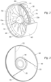
- a rotor 60 of the electric machine comprises a movable ring 62 in rotation inside a stator 66, which is connected by arms 70 to a cone 71 mounted upstream of the fan 12.
- the ring 62 carries permanent magnets 74. It will be understood that this configuration is not limiting of the invention, and that the ring 62 could for example include windings, the permanent magnets then being carried by the stator 66.
- This solution in any case makes it possible to dissociate the aerodynamic function of the blades 13 of the fan 12 from that of the torque transmission function of the electric machine, which is carried out by the arms 70 upstream of the blades 13 of the fan.
- the arms 70 being advantageously held circumferentially by the movable ring 62, the forces resulting from the centrifugal forces exerted on the arms 70 are compression forces which are able to be taken up in part by the ring which makes it possible to reduce the forces exerted on the arms 70.
- the blades 13 can therefore remain conventional blades which can be dismantled under the wings of the aircraft without requiring removal of the turbomachine 10, which is a significant advantage for airlines.
- the electric machine is also located outside the turbomachine 10, which facilitates its cooling and facilitates access for maintenance.
- a hub 76 of the rotor of the electric machine, linked to the ring 62, is fixed between two parts respectively upstream and downstream 72a, 72b of the cone 71 which is an adaptable cone replacing a conventional cone 72 as shown to the figure 4 .
- a rotating inlet cover 69 consisting of two parts fixed to each other, namely the cone 72, and a first external upstream flange 86 of the rim 82 on which this cone 72 is directly fixed.
- the cone 72 has a free end 83 in the shape of a point centered on the axis A of rotation of the inlet cover 69, which happens to correspond with the axis of the fan, and an end 85 for junction with the flange 86 which is substantially flush with the platforms 15 of the blades 13, so as to be placed in aerodynamic continuity therewith.
- the invention advantageously makes it possible to electrify a conventional turbomachine by substituting an adaptable cone 71 shown in Figure 6 to the original cone 72 of the turbomachine represented in figure 4 .
- This cone 71 is made in two parts upstream 71a and downstream 71b and it is intended to receive the rotor 60 of the electric machine. It is fixed in place of the cone
- a downstream part 71b of the adaptable cone 71 comprises a downstream end 88 which is fixed on the first external upstream flange 86 of the disc 80 and an upstream end provided with a second external upstream flange 90.
- the hub 76 of the rotor 60 of the electric machine which is connected by the arms 70 to the ring 62.
- the hub 76 comprises a substantially annular wall 92 having a downstream end 94 fixed to the second external upstream flange 90 of the downstream part 71b of the adaptable cone.
- the hub 76 has an upstream end provided with a third external upstream flange 93 which cooperates with the upstream part 71a of the adaptable cone 71.
- the hub 76 of the rotor 60 of the electric machine also includes a tubular internal web 94 which includes a grooved bore 96 allowing the coupling of the rotor hub of the electric machine to the fan shaft 54. It is therefore through this veil 94 that the torque of the electric machine travels.
- the upstream part 71a of the adaptable cone 71 comprises a downstream end 98 which, as we have seen, is fixed on the third external upstream flange 92 of the rotor hub 76 of the electric machine.
- the rotor 60 of the electric machine comprises at least two arms 70 connecting the hub 76 to the ring 62.
- the number of these arms be as small as possible. This is why preferably, the rotor 60 of the electric machine does not have more than three arms 70. Thus, the rotor of the electric machine has two or three arms 70 only.
- the fan 12 maintains a regular distribution of its blades 13.
- the arms 70 are arranged so that a blade 13 is located substantially, depending on the flow of the gas through the fan 12, in the wake of each arm 70.
- each arm 70 is substantially rectilinear. The air flow F is therefore minimally disturbed.
- each arm 70 can be purely radial, as illustrated in figure 2 .
- the arms can be tangent to the hub.
- each arm 70 has a junction end 78 with the hub 76 which is tangent with the hub 76.
- the stator 66 of the electrical machine includes an electrical utility harness 102 which is connected directly to a pylon (not shown) of the aircraft.
- such a kit 100 therefore comprises an adaptable cone 71 made in two parts respectively upstream and downstream 71a, 71b, and a rotor 60 of an electric machine comprising a rotor hub 76 of an electric machine connected by two or three arms 70 to a ring 62 comprising or carrying permanent magnets 74, which is intended to be fixed between the two upstream and downstream parts 71a, 71b of the adaptable cone 71.
- the downstream part 71b of the adaptable cone 71 is configured, in particular by its dimensions and fixing points, to be substituted for the conventional cone 72, and the hub 76 of the rotor 60 of an electric machine is configured to be fixed to the downstream part 71b of the adaptable cone 71 and to the fan shaft 54.
- the upstream part 71a of the cone 71 is configured to be fixed to the hub 76 of the rotor 60 of an electric machine.
- the kit 100 also includes a stator 66 which is configured to be fixed upstream of the fan casing 40.
- the stator 66 includes an electrical harness 102 which can be connected directly to a pylon (not shown) of the aircraft without modifying the existing turbomachine 10.
- the stator 66 may include a downstream annular face 104 which can be directly fixed to an upstream face 106 of the fan casing 40.
- this kit can be mounted on the turbomachine 10 one after the other. However, preferably, they will be in the form of an electrification module of a conventional turbomachine, pre-assembled and able to be transported as such to a production site.
- This module comprises the rotor 60 of the electric machine whose hub 76 is pre-assembled to the upstream and downstream parts 71a, 71b of adaptable cone 71, and the stator 66 surrounding the rotor 60.
- the rotor 60 is removably clamped relative to the stator 66 and it is only once assembled to the turbomachine 10 that these removable flanges are removed.
- a first step ET1 also represented in the figure 4 , we provide a conventional turbomachine 10.
- the electrification module comprising all the pre-assembled elements of the kit 100 is presented in front of the fan 12 of the turbomachine 10,
- a fourth step ET4 the stator 66 of the electric machine is fixed to the casing 40 and the adaptable cone 71, 71a, 71b, carrying the rotor 60 of the electric machine, to the disk 80 of the fan 12.
- the electrification module is connected to the aircraft.
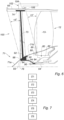
- the electrical utility harness 102 is connected to the aircraft. The result is the assembly of the Figure 6 .
- a sixth step ET6 the flanges connecting the stator 66 to the rotor 60 are removed.
- the invention therefore makes it possible to very simply ensure the electrification of a conventional turbomachine 10.
Landscapes
- Engineering & Computer Science (AREA)
- Mechanical Engineering (AREA)
- General Engineering & Computer Science (AREA)
- Chemical & Material Sciences (AREA)
- Combustion & Propulsion (AREA)
- Power Engineering (AREA)
- Aviation & Aerospace Engineering (AREA)
- Structures Of Non-Positive Displacement Pumps (AREA)
- Connection Of Motors, Electrical Generators, Mechanical Devices, And The Like (AREA)
Claims (10)
- Flugzeug-Turbomaschine (10), die ein drehbewegliches Gebläse (12) im Inneren eines Gehäuses (40) und eine elektrische Maschine umfasst, die einen fest mit dem Gebläse verbundenen Rotor (60) und einen fest mit dem Gehäuse (40) verbundenen Stator (66) umfasst,
dadurch gekennzeichnet, dass der Rotor (60) der elektrischen Maschine einen drehbeweglichen Ring (62) im Inneren des Stators (66) umfasst, der über Arme (70) mit einem Konus (71) verbunden ist, der stromaufwärts des Gebläses (12) angebracht ist. - Turbomaschine nach dem vorstehenden Anspruch, dadurch gekennzeichnet, dass eine Nabe (76) des Rotors der elektrischen Maschine, die mit dem Ring (62) verbunden ist, zwischen zwei, stromaufwärtigen bzw. stromabwärtigen, Teilen (71a, 71b) des Konus (71) befestigt ist.
- Turbomaschine (10) nach dem vorstehenden Anspruch, dadurch gekennzeichnet, dass eine Scheibe (80) des Gebläses (12) eine Felge (82) umfasst, die eine geriffelte Bohrung (84) umfasst, die die Kopplung der Gebläsescheibe (80) mit einer von der Turbomaschine (10) angetriebenen Gebläsewelle (54) ermöglicht, wobei die Ringfelge (82) mit einem ersten stromaufwärtigen äußeren Kragen (86) versehen ist, und dadurch, dass:- der stromabwärtige Teil (72b) des Konus (72) ein stromabwärtiges Ende (88) umfasst, das am ersten stromaufwärtigen äußeren Kragen (86) der Gebläsescheibe (80) befestigt ist, und ein stromaufwärtiges Ende, das mit einem zweiten stromaufwärtigen äußeren Kragen (90) versehen ist,- die Rotornabe (76) der elektrischen Maschine eine im Wesentlichen ringförmige Wand (92) umfasst, die ein stromabwärtiges Ende (94), das am zweiten stromaufwärtigen äußeren Kragen (90) befestigt ist, ein stromaufwärtiges Ende, das mit einem dritten stromaufwärtigen äußeren Kragen (92) versehen ist, und eine rohrförmige Innenbahn (94) umfasst, die eine geriffelte Bohrung (96) umfasst, die die Kopplung der Rotornabe (76) der elektrischen Maschine mit der Gebläsewelle (54) ermöglicht,- der stromaufwärtige Teil (72a) des Konus (72) ein stromabwärtiges Ende (98) umfasst, das am dritten stromaufwärtigen äußeren Kragen (92) der Rotornabe (76) der elektrischen Maschine befestigt ist.
- Turbomaschine (10) nach einem der Ansprüche 2 oder 3, dadurch gekennzeichnet, dass der Rotor (60) der elektrischen Maschine mindestens zwei Arme (70) umfasst, die die Nabe (76) mit dem Ring (62) verbinden.
- Turbomaschine (10) nach dem vorstehenden Anspruch, dadurch gekennzeichnet, dass der Rotor (60) der elektrischen Maschine zwei oder drei Arme (70) umfasst.
- Turbomaschine (10) nach einem der Ansprüche 4 oder 5, dadurch gekennzeichnet, dass jeder Arm (70) im Wesentlichen geradlinig ist und dadurch, dass sich eine Schaufel (13) des Gebläses (12) im Wesentlichen, gemäß der Strömung der Gase durch das Gebläse (12), im Anschluss an die Arm (70) befindet.
- Turbomaschine (10) nach dem vorstehenden Anspruch, dadurch gekennzeichnet, dass jeder Arm (70) ein Übergangsende (78) zur Nabe (76) umfasst, das zur Nabe tangential ist.
- Elektrifizierungsset (100) für eine konventionelle Turbomaschine (10) mit einer Achse A, die ein drehbewegliches Gebläse (12) im Inneren eines Gehäuses (40) umfasst, wobei das Gebläse (12) eine Scheibe (80) umfasst, die von einer von der Turbomaschine angetriebenen Gebläsewelle (54) drehend angetrieben wird und mit einem konventionellen Konus (72) versehen ist, der stromaufwärts der Scheibe (80) befestigt ist, dadurch gekennzeichnet, dass das Set (100) umfasst:- einen Stator (66), der so konfiguriert ist, dass er stromaufwärts des Gehäuses (40) befestigt werden kann,- einen anpassbaren Konus (72) aus zwei, stromaufwärtigen bzw. stromabwärtigen, Teilen (72a, 72b),- einen Rotor (60) einer elektrischen Maschine, der eine Rotornabe (76) der elektrischen Maschine umfasst, die über zwei oder drei Arme (70) mit einem Ring (62) verbunden ist und die dazu bestimmt ist, zwischen den zwei stromaufwärtigen und stromabwärtigen Teilen (72a, 72b) des anpassbaren Konus (72) befestigt zu werden,wobei der stromabwärtige Teil (71b) des anpassbaren Konus (71) so konfiguriert ist, dass er den konventionellen Konus (72) ersetzt, wobei die Nabe (76) des Rotors der elektrischen Maschine so konfiguriert ist, dass sie am stromabwärtigen Teil (71b) des anpassbaren Konus (71) und an der Gebläsewelle (54), die von einer Niederdruckwelle (44) der Turbomaschine angetrieben wird, befestigt werden kann, und wobei der stromaufwärtige Teil des Konus (71a) so konfiguriert ist, dass er an der Scheibe (80) des Rotors (62) der elektrischen Maschine befestigt werden kann.
- Elektrifizierungsmodul für eine konventionelle Turbomaschine, das eine modulare Anordnung von Elementen des Sets (100) nach dem vorstehenden Anspruch umfasst, wobei das Modul den Rotor (60) der elektrischen Maschine, dessen Nabe (76) mit dem stromaufwärtigen und dem stromabwärtigen Teil (72a, 72b) des anpassbaren Konus (72) zusammengebaut ist, und den Stator (66) umfasst, der den Rotor (60) umgibt und der in Bezug auf den Rotor (60) angeflanscht ist.
- Verfahren zum Elektrifizieren einer konventionellen Flugzeug-Turbomaschine (10) mit Hilfe eines Elektrifizierungsmoduls nach dem vorstehenden Anspruch, dadurch gekennzeichnet, dass es umfasst:- einen ersten Schritt (ET1), bei dem eine konventionelle Turbomaschine (10) bereitgestellt wird,- einen zweiten Schritt (ET2), bei dem der herkömmliche Konus (72) der Turbomaschine (10) ausgebaut wird,- einen dritten Schritt (ET3), bei dem das Elektrifizierungsmodul vor das Gebläse (12) der Turbomaschine (10) gebracht wird,- einen vierten Schritt (ET4), bei dem der Stator (66) der elektrischen Maschine am Gehäuse (40) und der anpassbare Konus (71), der den Rotor (60) der elektrischen Maschine trägt, an der Scheibe (80) des Gebläses (12) befestigt wird,- einen fünften Schritt (ET5) des elektrischen Anschließens des Elektrifizierungsmoduls an das Flugzeug,- einen optionalen sechsten Schritt (ET6), bei dem mindestens ein Flansch, der den Stator (66) mit dem Rotor (60) verbindet, entfernt wird.
Applications Claiming Priority (2)
| Application Number | Priority Date | Filing Date | Title |
|---|---|---|---|
| FR1859937A FR3087822B1 (fr) | 2018-10-26 | 2018-10-26 | Turbomachine a machine electrique comportant un anneau de rotor accole a la soufflante |
| PCT/FR2019/052554 WO2020084270A1 (fr) | 2018-10-26 | 2019-10-25 | Turbomachine a machine electrique comportant un anneau de rotor accole a la soufflante |
Publications (2)
| Publication Number | Publication Date |
|---|---|
| EP3870811A1 EP3870811A1 (de) | 2021-09-01 |
| EP3870811B1 true EP3870811B1 (de) | 2024-02-07 |
Family
ID=65444109
Family Applications (1)
| Application Number | Title | Priority Date | Filing Date |
|---|---|---|---|
| EP19813383.7A Active EP3870811B1 (de) | 2018-10-26 | 2019-10-25 | Turbomaschine mit einer elektrischen maschine mit einem an dem gebläse angebundenen ring |
Country Status (5)
| Country | Link |
|---|---|
| US (1) | US11591987B2 (de) |
| EP (1) | EP3870811B1 (de) |
| CN (1) | CN112996986B (de) |
| FR (1) | FR3087822B1 (de) |
| WO (1) | WO2020084270A1 (de) |
Families Citing this family (4)
| Publication number | Priority date | Publication date | Assignee | Title |
|---|---|---|---|---|
| WO2023067527A1 (en) * | 2021-10-19 | 2023-04-27 | Duxion Motors, Inc. | Hybrid propulsion system |
| CN115013184B (zh) * | 2022-07-05 | 2025-12-05 | 中国航发贵阳发动机设计研究所 | 一种直驱式中大涵道比航空发动机 |
| FR3140866B1 (fr) * | 2022-10-18 | 2024-08-30 | Airbus Helicopters | procédé et aéronef muni d’au moins un moteur à combustion et d’un système d’entraînement à au moins deux machines électriques |
| US12410726B1 (en) * | 2024-06-05 | 2025-09-09 | Rtx Corporation | Turbine engine centerbody generator |
Family Cites Families (15)
| Publication number | Priority date | Publication date | Assignee | Title |
|---|---|---|---|---|
| DE102004004945A1 (de) * | 2004-01-31 | 2005-08-18 | Mtu Aero Engines Gmbh | Gasturbine, insbesondere Flugtriebwerk |
| DE102005046208A1 (de) | 2005-09-28 | 2007-03-29 | Mtu Aero Engines Gmbh | Strahltriebwerk |
| US7690186B2 (en) * | 2005-11-09 | 2010-04-06 | Pratt & Whitney Canada Corp. | Gas turbine engine including apparatus to transfer power between multiple shafts |
| US8803354B2 (en) * | 2006-12-20 | 2014-08-12 | Unimodal Systems Llc | Modular electric generator for variable speed turbines |
| FR2919896B1 (fr) * | 2007-08-07 | 2009-10-30 | Snecma Sa | Turboreacteur comprenant un generateur de courant monte dans la soufflante et un procede de montage dudit generateur dans la soufflante |
| FR2921978B1 (fr) | 2007-10-08 | 2014-04-11 | Snecma | Turboreacteur a generateur electrique agence dans la soufflante |
| CA2903320C (en) * | 2013-03-03 | 2019-07-16 | Rolls-Royce North American Technologies, Inc. | Gas turbine engine |
| BE1024024B1 (fr) * | 2014-10-09 | 2017-10-30 | Safran Aero Boosters S.A. | Compresseur de turbomachine axiale avec rotor contrarotatif |
| WO2016126231A1 (en) * | 2015-02-02 | 2016-08-11 | Samuelson Devin G | Rotational ducted fan (rdf) propulsion system |
| DE102015214255A1 (de) * | 2015-07-28 | 2017-02-02 | Siemens Aktiengesellschaft | Triebwerk für ein Luftfahrzeug sowie Luftfahrzeug oder Tragflächenflugzeug mit einem Triebwerk |
| EP3246526B1 (de) * | 2016-05-18 | 2021-03-24 | Rolls-Royce Corporation | Steuerung eines niedrigdruckwellengenerators für einen gasturbinenmotor |
| US10793281B2 (en) * | 2017-02-10 | 2020-10-06 | General Electric Company | Propulsion system for an aircraft |
| US10931168B2 (en) * | 2018-03-27 | 2021-02-23 | Williams International Co., L.L.C. | Radial-flux shrouded-fan generator |
| US10794216B2 (en) * | 2018-06-19 | 2020-10-06 | Raytheon Technologies Corporation | Fan drive gear system DC motor and generator |
| FR3087821B1 (fr) * | 2018-10-26 | 2021-12-03 | Safran Aircraft Engines | Module electrique de soufflante d'aeronef comportant des aubes a fixation perfectionnee |
-
2018
- 2018-10-26 FR FR1859937A patent/FR3087822B1/fr active Active
-
2019
- 2019-10-25 CN CN201980074291.XA patent/CN112996986B/zh active Active
- 2019-10-25 WO PCT/FR2019/052554 patent/WO2020084270A1/fr not_active Ceased
- 2019-10-25 EP EP19813383.7A patent/EP3870811B1/de active Active
- 2019-10-25 US US17/287,427 patent/US11591987B2/en active Active
Also Published As
| Publication number | Publication date |
|---|---|
| EP3870811A1 (de) | 2021-09-01 |
| CN112996986A (zh) | 2021-06-18 |
| US20210355893A1 (en) | 2021-11-18 |
| FR3087822B1 (fr) | 2020-11-06 |
| CN112996986B (zh) | 2023-06-30 |
| WO2020084270A1 (fr) | 2020-04-30 |
| FR3087822A1 (fr) | 2020-05-01 |
| US11591987B2 (en) | 2023-02-28 |
Similar Documents
| Publication | Publication Date | Title |
|---|---|---|
| EP3870811B1 (de) | Turbomaschine mit einer elektrischen maschine mit einem an dem gebläse angebundenen ring | |
| EP4069944B1 (de) | Elektrische verbindung einer elektrischen maschine in einem flugzeugtriebwerk | |
| EP3377732B1 (de) | Vorderer teil einer turbomaschine | |
| CA2837498C (fr) | Distributeur de turbine radiale a calage variable, en particulier de turbine de source de puissance auxiliaire | |
| FR3027053B1 (fr) | Stator de turbomachine d'aeronef | |
| FR2908461A1 (fr) | Generateur de secours a turboreacteur a double flux | |
| EP3870809A1 (de) | Elektrisches modul für ein flugzeuggebläse mit schaufeln mit verbesserter befestigung | |
| EP3361055A1 (de) | Kompressor mit segmentiertem innenring für axiale turbomaschine | |
| FR2981686A1 (fr) | Turbomachine comprenant un recepteur a helices contrarotatives supporte par une enveloppe structurale fixee au carter intermediaire | |
| FR3087824A1 (fr) | Module electrique de soufflante d'aeronef comportant des aubes a fixation amelioree | |
| FR3090049A1 (fr) | Turbomachine comportant un alternateur entre deux elements contrarotatifs | |
| EP4127438A1 (de) | Turbinenmotormodul mit einer elektrischen maschine | |
| WO2021181028A1 (fr) | Reducteur de vitesse equipe d'une machine electrique | |
| EP4069948B1 (de) | Elektrisches modul für eine turbomaschine eines flugzeugs | |
| EP4069946B1 (de) | Elektrische verbindung für eine elektrische maschine in einem flugzeugturbinenmotor | |
| EP4240949A1 (de) | Flugzeug-doppelflussturbinenmotoranordnung mit einfallsgesteuerten luftaustrittsrippen | |
| FR3039206A1 (fr) | Turbomachine pour aeronef comportant une turbine libre dans le flux primaire | |
| EP4214403B1 (de) | Elektrische verbindung einer elektrischen maschine in einem flugzeugturbinentriebwerk | |
| FR3086001A1 (fr) | Systeme de propulsion d'aeronef a soufflante disposee a une extremite arriere du fuselage | |
| BE1027469A1 (fr) | Architecture de turbomachine avec booster accéléré | |
| WO2024100356A1 (fr) | Système propulsif aéronautique à rendement propulsif amélioré | |
| EP4630673A1 (de) | Flugzeugantriebsanordnung | |
| FR3154100A1 (fr) | Soufflante carénée pour une turbomachine d’aéronef | |
| WO2026008944A1 (fr) | Systeme de trains epicycloidaux pour turbomachine et turbomachine comprenant un tel systeme | |
| EP4702219A2 (de) | Gehäuse für ein flugzeugturbinentriebwerk |
Legal Events
| Date | Code | Title | Description |
|---|---|---|---|
| STAA | Information on the status of an ep patent application or granted ep patent |
Free format text: STATUS: UNKNOWN |
|
| STAA | Information on the status of an ep patent application or granted ep patent |
Free format text: STATUS: THE INTERNATIONAL PUBLICATION HAS BEEN MADE |
|
| PUAI | Public reference made under article 153(3) epc to a published international application that has entered the european phase |
Free format text: ORIGINAL CODE: 0009012 |
|
| STAA | Information on the status of an ep patent application or granted ep patent |
Free format text: STATUS: REQUEST FOR EXAMINATION WAS MADE |
|
| 17P | Request for examination filed |
Effective date: 20210518 |
|
| AK | Designated contracting states |
Kind code of ref document: A1 Designated state(s): AL AT BE BG CH CY CZ DE DK EE ES FI FR GB GR HR HU IE IS IT LI LT LU LV MC MK MT NL NO PL PT RO RS SE SI SK SM TR |
|
| DAV | Request for validation of the european patent (deleted) | ||
| DAX | Request for extension of the european patent (deleted) | ||
| GRAP | Despatch of communication of intention to grant a patent |
Free format text: ORIGINAL CODE: EPIDOSNIGR1 |
|
| STAA | Information on the status of an ep patent application or granted ep patent |
Free format text: STATUS: GRANT OF PATENT IS INTENDED |
|
| INTG | Intention to grant announced |
Effective date: 20230828 |
|
| GRAS | Grant fee paid |
Free format text: ORIGINAL CODE: EPIDOSNIGR3 |
|
| GRAA | (expected) grant |
Free format text: ORIGINAL CODE: 0009210 |
|
| STAA | Information on the status of an ep patent application or granted ep patent |
Free format text: STATUS: THE PATENT HAS BEEN GRANTED |
|
| AK | Designated contracting states |
Kind code of ref document: B1 Designated state(s): AL AT BE BG CH CY CZ DE DK EE ES FI FR GB GR HR HU IE IS IT LI LT LU LV MC MK MT NL NO PL PT RO RS SE SI SK SM TR |
|
| REG | Reference to a national code |
Ref country code: GB Ref legal event code: FG4D Free format text: NOT ENGLISH |
|
| REG | Reference to a national code |
Ref country code: CH Ref legal event code: EP |
|
| REG | Reference to a national code |
Ref country code: IE Ref legal event code: FG4D Free format text: LANGUAGE OF EP DOCUMENT: FRENCH |
|
| REG | Reference to a national code |
Ref country code: DE Ref legal event code: R096 Ref document number: 602019046240 Country of ref document: DE |
|
| REG | Reference to a national code |
Ref country code: LT Ref legal event code: MG9D |
|
| REG | Reference to a national code |
Ref country code: NL Ref legal event code: MP Effective date: 20240207 |
|
| PG25 | Lapsed in a contracting state [announced via postgrant information from national office to epo] |
Ref country code: IS Free format text: LAPSE BECAUSE OF FAILURE TO SUBMIT A TRANSLATION OF THE DESCRIPTION OR TO PAY THE FEE WITHIN THE PRESCRIBED TIME-LIMIT Effective date: 20240607 |
|
| PG25 | Lapsed in a contracting state [announced via postgrant information from national office to epo] |
Ref country code: LT Free format text: LAPSE BECAUSE OF FAILURE TO SUBMIT A TRANSLATION OF THE DESCRIPTION OR TO PAY THE FEE WITHIN THE PRESCRIBED TIME-LIMIT Effective date: 20240207 |
|
| PG25 | Lapsed in a contracting state [announced via postgrant information from national office to epo] |
Ref country code: GR Free format text: LAPSE BECAUSE OF FAILURE TO SUBMIT A TRANSLATION OF THE DESCRIPTION OR TO PAY THE FEE WITHIN THE PRESCRIBED TIME-LIMIT Effective date: 20240508 |
|
| REG | Reference to a national code |
Ref country code: AT Ref legal event code: MK05 Ref document number: 1655506 Country of ref document: AT Kind code of ref document: T Effective date: 20240207 |
|
| PG25 | Lapsed in a contracting state [announced via postgrant information from national office to epo] |
Ref country code: HR Free format text: LAPSE BECAUSE OF FAILURE TO SUBMIT A TRANSLATION OF THE DESCRIPTION OR TO PAY THE FEE WITHIN THE PRESCRIBED TIME-LIMIT Effective date: 20240207 Ref country code: NL Free format text: LAPSE BECAUSE OF FAILURE TO SUBMIT A TRANSLATION OF THE DESCRIPTION OR TO PAY THE FEE WITHIN THE PRESCRIBED TIME-LIMIT Effective date: 20240207 Ref country code: RS Free format text: LAPSE BECAUSE OF FAILURE TO SUBMIT A TRANSLATION OF THE DESCRIPTION OR TO PAY THE FEE WITHIN THE PRESCRIBED TIME-LIMIT Effective date: 20240507 |
|
| PG25 | Lapsed in a contracting state [announced via postgrant information from national office to epo] |
Ref country code: ES Free format text: LAPSE BECAUSE OF FAILURE TO SUBMIT A TRANSLATION OF THE DESCRIPTION OR TO PAY THE FEE WITHIN THE PRESCRIBED TIME-LIMIT Effective date: 20240207 |
|
| PG25 | Lapsed in a contracting state [announced via postgrant information from national office to epo] |
Ref country code: AT Free format text: LAPSE BECAUSE OF FAILURE TO SUBMIT A TRANSLATION OF THE DESCRIPTION OR TO PAY THE FEE WITHIN THE PRESCRIBED TIME-LIMIT Effective date: 20240207 |
|
| PG25 | Lapsed in a contracting state [announced via postgrant information from national office to epo] |
Ref country code: RS Free format text: LAPSE BECAUSE OF FAILURE TO SUBMIT A TRANSLATION OF THE DESCRIPTION OR TO PAY THE FEE WITHIN THE PRESCRIBED TIME-LIMIT Effective date: 20240507 Ref country code: NO Free format text: LAPSE BECAUSE OF FAILURE TO SUBMIT A TRANSLATION OF THE DESCRIPTION OR TO PAY THE FEE WITHIN THE PRESCRIBED TIME-LIMIT Effective date: 20240507 Ref country code: NL Free format text: LAPSE BECAUSE OF FAILURE TO SUBMIT A TRANSLATION OF THE DESCRIPTION OR TO PAY THE FEE WITHIN THE PRESCRIBED TIME-LIMIT Effective date: 20240207 Ref country code: LT Free format text: LAPSE BECAUSE OF FAILURE TO SUBMIT A TRANSLATION OF THE DESCRIPTION OR TO PAY THE FEE WITHIN THE PRESCRIBED TIME-LIMIT Effective date: 20240207 Ref country code: IS Free format text: LAPSE BECAUSE OF FAILURE TO SUBMIT A TRANSLATION OF THE DESCRIPTION OR TO PAY THE FEE WITHIN THE PRESCRIBED TIME-LIMIT Effective date: 20240607 Ref country code: HR Free format text: LAPSE BECAUSE OF FAILURE TO SUBMIT A TRANSLATION OF THE DESCRIPTION OR TO PAY THE FEE WITHIN THE PRESCRIBED TIME-LIMIT Effective date: 20240207 Ref country code: GR Free format text: LAPSE BECAUSE OF FAILURE TO SUBMIT A TRANSLATION OF THE DESCRIPTION OR TO PAY THE FEE WITHIN THE PRESCRIBED TIME-LIMIT Effective date: 20240508 Ref country code: FI Free format text: LAPSE BECAUSE OF FAILURE TO SUBMIT A TRANSLATION OF THE DESCRIPTION OR TO PAY THE FEE WITHIN THE PRESCRIBED TIME-LIMIT Effective date: 20240207 Ref country code: ES Free format text: LAPSE BECAUSE OF FAILURE TO SUBMIT A TRANSLATION OF THE DESCRIPTION OR TO PAY THE FEE WITHIN THE PRESCRIBED TIME-LIMIT Effective date: 20240207 Ref country code: BG Free format text: LAPSE BECAUSE OF FAILURE TO SUBMIT A TRANSLATION OF THE DESCRIPTION OR TO PAY THE FEE WITHIN THE PRESCRIBED TIME-LIMIT Effective date: 20240207 Ref country code: AT Free format text: LAPSE BECAUSE OF FAILURE TO SUBMIT A TRANSLATION OF THE DESCRIPTION OR TO PAY THE FEE WITHIN THE PRESCRIBED TIME-LIMIT Effective date: 20240207 |
|
| PG25 | Lapsed in a contracting state [announced via postgrant information from national office to epo] |
Ref country code: PT Free format text: LAPSE BECAUSE OF FAILURE TO SUBMIT A TRANSLATION OF THE DESCRIPTION OR TO PAY THE FEE WITHIN THE PRESCRIBED TIME-LIMIT Effective date: 20240607 Ref country code: PL Free format text: LAPSE BECAUSE OF FAILURE TO SUBMIT A TRANSLATION OF THE DESCRIPTION OR TO PAY THE FEE WITHIN THE PRESCRIBED TIME-LIMIT Effective date: 20240207 |
|
| PG25 | Lapsed in a contracting state [announced via postgrant information from national office to epo] |
Ref country code: SE Free format text: LAPSE BECAUSE OF FAILURE TO SUBMIT A TRANSLATION OF THE DESCRIPTION OR TO PAY THE FEE WITHIN THE PRESCRIBED TIME-LIMIT Effective date: 20240207 Ref country code: PT Free format text: LAPSE BECAUSE OF FAILURE TO SUBMIT A TRANSLATION OF THE DESCRIPTION OR TO PAY THE FEE WITHIN THE PRESCRIBED TIME-LIMIT Effective date: 20240607 Ref country code: PL Free format text: LAPSE BECAUSE OF FAILURE TO SUBMIT A TRANSLATION OF THE DESCRIPTION OR TO PAY THE FEE WITHIN THE PRESCRIBED TIME-LIMIT Effective date: 20240207 Ref country code: LV Free format text: LAPSE BECAUSE OF FAILURE TO SUBMIT A TRANSLATION OF THE DESCRIPTION OR TO PAY THE FEE WITHIN THE PRESCRIBED TIME-LIMIT Effective date: 20240207 |
|
| PG25 | Lapsed in a contracting state [announced via postgrant information from national office to epo] |
Ref country code: DK Free format text: LAPSE BECAUSE OF FAILURE TO SUBMIT A TRANSLATION OF THE DESCRIPTION OR TO PAY THE FEE WITHIN THE PRESCRIBED TIME-LIMIT Effective date: 20240207 |
|
| PG25 | Lapsed in a contracting state [announced via postgrant information from national office to epo] |
Ref country code: SM Free format text: LAPSE BECAUSE OF FAILURE TO SUBMIT A TRANSLATION OF THE DESCRIPTION OR TO PAY THE FEE WITHIN THE PRESCRIBED TIME-LIMIT Effective date: 20240207 |
|
| PG25 | Lapsed in a contracting state [announced via postgrant information from national office to epo] |
Ref country code: CZ Free format text: LAPSE BECAUSE OF FAILURE TO SUBMIT A TRANSLATION OF THE DESCRIPTION OR TO PAY THE FEE WITHIN THE PRESCRIBED TIME-LIMIT Effective date: 20240207 Ref country code: EE Free format text: LAPSE BECAUSE OF FAILURE TO SUBMIT A TRANSLATION OF THE DESCRIPTION OR TO PAY THE FEE WITHIN THE PRESCRIBED TIME-LIMIT Effective date: 20240207 |
|
| PG25 | Lapsed in a contracting state [announced via postgrant information from national office to epo] |
Ref country code: SK Free format text: LAPSE BECAUSE OF FAILURE TO SUBMIT A TRANSLATION OF THE DESCRIPTION OR TO PAY THE FEE WITHIN THE PRESCRIBED TIME-LIMIT Effective date: 20240207 |
|
| PG25 | Lapsed in a contracting state [announced via postgrant information from national office to epo] |
Ref country code: SM Free format text: LAPSE BECAUSE OF FAILURE TO SUBMIT A TRANSLATION OF THE DESCRIPTION OR TO PAY THE FEE WITHIN THE PRESCRIBED TIME-LIMIT Effective date: 20240207 Ref country code: SK Free format text: LAPSE BECAUSE OF FAILURE TO SUBMIT A TRANSLATION OF THE DESCRIPTION OR TO PAY THE FEE WITHIN THE PRESCRIBED TIME-LIMIT Effective date: 20240207 Ref country code: RO Free format text: LAPSE BECAUSE OF FAILURE TO SUBMIT A TRANSLATION OF THE DESCRIPTION OR TO PAY THE FEE WITHIN THE PRESCRIBED TIME-LIMIT Effective date: 20240207 Ref country code: EE Free format text: LAPSE BECAUSE OF FAILURE TO SUBMIT A TRANSLATION OF THE DESCRIPTION OR TO PAY THE FEE WITHIN THE PRESCRIBED TIME-LIMIT Effective date: 20240207 Ref country code: DK Free format text: LAPSE BECAUSE OF FAILURE TO SUBMIT A TRANSLATION OF THE DESCRIPTION OR TO PAY THE FEE WITHIN THE PRESCRIBED TIME-LIMIT Effective date: 20240207 Ref country code: CZ Free format text: LAPSE BECAUSE OF FAILURE TO SUBMIT A TRANSLATION OF THE DESCRIPTION OR TO PAY THE FEE WITHIN THE PRESCRIBED TIME-LIMIT Effective date: 20240207 |
|
| REG | Reference to a national code |
Ref country code: DE Ref legal event code: R097 Ref document number: 602019046240 Country of ref document: DE |
|
| PG25 | Lapsed in a contracting state [announced via postgrant information from national office to epo] |
Ref country code: IT Free format text: LAPSE BECAUSE OF FAILURE TO SUBMIT A TRANSLATION OF THE DESCRIPTION OR TO PAY THE FEE WITHIN THE PRESCRIBED TIME-LIMIT Effective date: 20240207 |
|
| PLBE | No opposition filed within time limit |
Free format text: ORIGINAL CODE: 0009261 |
|
| STAA | Information on the status of an ep patent application or granted ep patent |
Free format text: STATUS: NO OPPOSITION FILED WITHIN TIME LIMIT |
|
| PG25 | Lapsed in a contracting state [announced via postgrant information from national office to epo] |
Ref country code: IT Free format text: LAPSE BECAUSE OF FAILURE TO SUBMIT A TRANSLATION OF THE DESCRIPTION OR TO PAY THE FEE WITHIN THE PRESCRIBED TIME-LIMIT Effective date: 20240207 |
|
| 26N | No opposition filed |
Effective date: 20241108 |
|
| PG25 | Lapsed in a contracting state [announced via postgrant information from national office to epo] |
Ref country code: SI Free format text: LAPSE BECAUSE OF FAILURE TO SUBMIT A TRANSLATION OF THE DESCRIPTION OR TO PAY THE FEE WITHIN THE PRESCRIBED TIME-LIMIT Effective date: 20240207 |
|
| REG | Reference to a national code |
Ref country code: CH Ref legal event code: PL |
|
| PG25 | Lapsed in a contracting state [announced via postgrant information from national office to epo] |
Ref country code: MC Free format text: LAPSE BECAUSE OF FAILURE TO SUBMIT A TRANSLATION OF THE DESCRIPTION OR TO PAY THE FEE WITHIN THE PRESCRIBED TIME-LIMIT Effective date: 20240207 |
|
| PG25 | Lapsed in a contracting state [announced via postgrant information from national office to epo] |
Ref country code: BE Free format text: LAPSE BECAUSE OF NON-PAYMENT OF DUE FEES Effective date: 20241031 Ref country code: LU Free format text: LAPSE BECAUSE OF NON-PAYMENT OF DUE FEES Effective date: 20241025 |
|
| PG25 | Lapsed in a contracting state [announced via postgrant information from national office to epo] |
Ref country code: CH Free format text: LAPSE BECAUSE OF NON-PAYMENT OF DUE FEES Effective date: 20241031 |
|
| REG | Reference to a national code |
Ref country code: BE Ref legal event code: MM Effective date: 20241031 |
|
| PG25 | Lapsed in a contracting state [announced via postgrant information from national office to epo] |
Ref country code: IE Free format text: LAPSE BECAUSE OF NON-PAYMENT OF DUE FEES Effective date: 20241025 |
|
| PGFP | Annual fee paid to national office [announced via postgrant information from national office to epo] |
Ref country code: DE Payment date: 20251020 Year of fee payment: 7 |
|
| PGFP | Annual fee paid to national office [announced via postgrant information from national office to epo] |
Ref country code: GB Payment date: 20251029 Year of fee payment: 7 |
|
| PGFP | Annual fee paid to national office [announced via postgrant information from national office to epo] |
Ref country code: FR Payment date: 20251024 Year of fee payment: 7 |
|
| PG25 | Lapsed in a contracting state [announced via postgrant information from national office to epo] |
Ref country code: CY Free format text: LAPSE BECAUSE OF FAILURE TO SUBMIT A TRANSLATION OF THE DESCRIPTION OR TO PAY THE FEE WITHIN THE PRESCRIBED TIME-LIMIT; INVALID AB INITIO Effective date: 20191025 |
|
| PG25 | Lapsed in a contracting state [announced via postgrant information from national office to epo] |
Ref country code: HU Free format text: LAPSE BECAUSE OF FAILURE TO SUBMIT A TRANSLATION OF THE DESCRIPTION OR TO PAY THE FEE WITHIN THE PRESCRIBED TIME-LIMIT; INVALID AB INITIO Effective date: 20191025 |