EP4069948B1 - Elektrisches modul für eine turbomaschine eines flugzeugs - Google Patents
Elektrisches modul für eine turbomaschine eines flugzeugs Download PDFInfo
- Publication number
- EP4069948B1 EP4069948B1 EP20820507.0A EP20820507A EP4069948B1 EP 4069948 B1 EP4069948 B1 EP 4069948B1 EP 20820507 A EP20820507 A EP 20820507A EP 4069948 B1 EP4069948 B1 EP 4069948B1
- Authority
- EP
- European Patent Office
- Prior art keywords
- annular
- turbomachine
- stator
- support
- module
- Prior art date
- Legal status (The legal status is an assumption and is not a legal conclusion. Google has not performed a legal analysis and makes no representation as to the accuracy of the status listed.)
- Active
Links
Images




Classifications
-
- F—MECHANICAL ENGINEERING; LIGHTING; HEATING; WEAPONS; BLASTING
- F01—MACHINES OR ENGINES IN GENERAL; ENGINE PLANTS IN GENERAL; STEAM ENGINES
- F01D—NON-POSITIVE DISPLACEMENT MACHINES OR ENGINES, e.g. STEAM TURBINES
- F01D15/00—Adaptations of machines or engines for special use; Combinations of engines with devices driven thereby
- F01D15/10—Adaptations for driving, or combinations with, electric generators
-
- F—MECHANICAL ENGINEERING; LIGHTING; HEATING; WEAPONS; BLASTING
- F01—MACHINES OR ENGINES IN GENERAL; ENGINE PLANTS IN GENERAL; STEAM ENGINES
- F01D—NON-POSITIVE DISPLACEMENT MACHINES OR ENGINES, e.g. STEAM TURBINES
- F01D9/00—Stators
- F01D9/06—Fluid supply conduits to nozzles or the like
- F01D9/065—Fluid supply or removal conduits traversing the working fluid flow, e.g. for lubrication-, cooling-, or sealing fluids
-
- F—MECHANICAL ENGINEERING; LIGHTING; HEATING; WEAPONS; BLASTING
- F05—INDEXING SCHEMES RELATING TO ENGINES OR PUMPS IN VARIOUS SUBCLASSES OF CLASSES F01-F04
- F05D—INDEXING SCHEME FOR ASPECTS RELATING TO NON-POSITIVE-DISPLACEMENT MACHINES OR ENGINES, GAS-TURBINES OR JET-PROPULSION PLANTS
- F05D2220/00—Application
- F05D2220/30—Application in turbines
- F05D2220/32—Application in turbines in gas turbines
- F05D2220/323—Application in turbines in gas turbines for aircraft propulsion, e.g. jet engines
-
- F—MECHANICAL ENGINEERING; LIGHTING; HEATING; WEAPONS; BLASTING
- F05—INDEXING SCHEMES RELATING TO ENGINES OR PUMPS IN VARIOUS SUBCLASSES OF CLASSES F01-F04
- F05D—INDEXING SCHEME FOR ASPECTS RELATING TO NON-POSITIVE-DISPLACEMENT MACHINES OR ENGINES, GAS-TURBINES OR JET-PROPULSION PLANTS
- F05D2220/00—Application
- F05D2220/70—Application in combination with
-
- F—MECHANICAL ENGINEERING; LIGHTING; HEATING; WEAPONS; BLASTING
- F05—INDEXING SCHEMES RELATING TO ENGINES OR PUMPS IN VARIOUS SUBCLASSES OF CLASSES F01-F04
- F05D—INDEXING SCHEME FOR ASPECTS RELATING TO NON-POSITIVE-DISPLACEMENT MACHINES OR ENGINES, GAS-TURBINES OR JET-PROPULSION PLANTS
- F05D2220/00—Application
- F05D2220/70—Application in combination with
- F05D2220/76—Application in combination with an electrical generator
-
- F—MECHANICAL ENGINEERING; LIGHTING; HEATING; WEAPONS; BLASTING
- F05—INDEXING SCHEMES RELATING TO ENGINES OR PUMPS IN VARIOUS SUBCLASSES OF CLASSES F01-F04
- F05D—INDEXING SCHEME FOR ASPECTS RELATING TO NON-POSITIVE-DISPLACEMENT MACHINES OR ENGINES, GAS-TURBINES OR JET-PROPULSION PLANTS
- F05D2230/00—Manufacture
- F05D2230/60—Assembly methods
- F05D2230/61—Assembly methods using limited numbers of standard modules which can be adapted by machining
-
- F—MECHANICAL ENGINEERING; LIGHTING; HEATING; WEAPONS; BLASTING
- F05—INDEXING SCHEMES RELATING TO ENGINES OR PUMPS IN VARIOUS SUBCLASSES OF CLASSES F01-F04
- F05D—INDEXING SCHEME FOR ASPECTS RELATING TO NON-POSITIVE-DISPLACEMENT MACHINES OR ENGINES, GAS-TURBINES OR JET-PROPULSION PLANTS
- F05D2230/00—Manufacture
- F05D2230/72—Maintenance
-
- F—MECHANICAL ENGINEERING; LIGHTING; HEATING; WEAPONS; BLASTING
- F05—INDEXING SCHEMES RELATING TO ENGINES OR PUMPS IN VARIOUS SUBCLASSES OF CLASSES F01-F04
- F05D—INDEXING SCHEME FOR ASPECTS RELATING TO NON-POSITIVE-DISPLACEMENT MACHINES OR ENGINES, GAS-TURBINES OR JET-PROPULSION PLANTS
- F05D2240/00—Components
- F05D2240/10—Stators
- F05D2240/12—Fluid guiding means, e.g. vanes
-
- F—MECHANICAL ENGINEERING; LIGHTING; HEATING; WEAPONS; BLASTING
- F05—INDEXING SCHEMES RELATING TO ENGINES OR PUMPS IN VARIOUS SUBCLASSES OF CLASSES F01-F04
- F05D—INDEXING SCHEME FOR ASPECTS RELATING TO NON-POSITIVE-DISPLACEMENT MACHINES OR ENGINES, GAS-TURBINES OR JET-PROPULSION PLANTS
- F05D2250/00—Geometry
- F05D2250/70—Shape
- F05D2250/75—Shape given by its similarity to a letter, e.g. T-shaped
-
- Y—GENERAL TAGGING OF NEW TECHNOLOGICAL DEVELOPMENTS; GENERAL TAGGING OF CROSS-SECTIONAL TECHNOLOGIES SPANNING OVER SEVERAL SECTIONS OF THE IPC; TECHNICAL SUBJECTS COVERED BY FORMER USPC CROSS-REFERENCE ART COLLECTIONS [XRACs] AND DIGESTS
- Y02—TECHNOLOGIES OR APPLICATIONS FOR MITIGATION OR ADAPTATION AGAINST CLIMATE CHANGE
- Y02T—CLIMATE CHANGE MITIGATION TECHNOLOGIES RELATED TO TRANSPORTATION
- Y02T50/00—Aeronautics or air transport
- Y02T50/60—Efficient propulsion technologies, e.g. for aircraft
Definitions
- the present invention relates to an electrical module for an aircraft turbomachine as well as a method of maintaining this turbomachine.
- the state of the art includes in particular the documents FR-A1-2 842 565 , FR-A1-2 896 537 And FR-A1-2 922 265 which describe turbomachines equipped with electrical machines.
- the state of the art also includes the documents GB-A-1 141 001 , US-A-3,264,482 , EP-A1-3 246 528 And EP-A1-3 553 295 .
- the turbomachine comprises a low pressure body and a high pressure body, each body comprising a shaft connecting a rotor of a compressor to a rotor of a turbine.
- an electric machine is an electromechanical device based on electromagnetism allowing the conversion of electrical energy, for example into work or mechanical energy. This process is reversible and can be used to produce electricity.
- An electric machine can also behave in motor mode as well as in generator mode.
- a solution to this problem would consist of integrating the electric machine directly downstream of the turbomachine fan.
- a difficulty would be the connection of this machine to the electronic power circuit which is generally located at a distance from the machine.
- harnesses would pose some technical problems in this environment. Large diameter harnesses have very large bending radii, which would not be compatible with this environment. The integration of harnesses would require supports to limit the transmission of vibrations to surrounding parts and their damage.
- the present invention proposes a solution to at least part of the problems mentioned in the above.
- module an assembly of elements which is configured to be attached in a simplified and rapid manner to another module, that is to say to another assembly of parts.
- the modularity of a turbomachine is advantageous in that it facilitates and therefore makes its assembly and disassembly more economical, in the context of a maintenance operation for example.
- the module according to the invention represents a part of an electric machine, namely the part comprising the stator of the electric machine.
- This module is intended to be fixed to a fixed or stator element of the turbomachine, forming part of another module, and to surround the rotor of the electric machine which is also intended to be fixed to another element or module, this -this time of rotor, of the turbomachine.
- the electrical module is for example fixed to a module comprising an inlet casing of the turbomachine, and the rotor of the electric machine is for example fixed to a fan module of the turbomachine.
- the electrical module essentially comprises two parts, namely the stator and its support element.
- This support element is formed by the assembly of an annular support and a cover which is intended to be swept by a flow of gas in order to cool the stator of the electrical machine by conduction.
- the present invention thus proposes a solution for integrating an electrical machine, a first advantage being linked to the fact that in the integration zone of this machine, ideally directly downstream of the blower and therefore upstream of the compressor(s), the temperatures there are relatively low and therefore optimal for this machine.
- the rotor of the machine is driven by the fan and is therefore at a relatively low speed, particularly if the turbomachine includes a reduction gear.
- the machine is located as close as possible to the flow veins and has a relatively large diameter and can thus produce significant powers compared to machines of previous technologies.
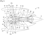
- FIG. 1 schematically represents an aircraft turbomachine 10 with a double body and double flow.
- the turbomachine 10 conventionally comprises a gas generator 12 upstream of which a fan 14 is arranged.
- the fan 14 is surrounded by a casing 16 which is surrounded by a nacelle 18 which extends around and along a majority of the gas generator 12.
- the gas generator 12 here comprises two bodies, namely a low pressure body 12a or LP and a high pressure body 12b or HP. Each body includes a compressor and a turbine.
- upstream and downstream are considered according to a main direction F of gas flow in the turbomachine 10, this direction F being parallel to the longitudinal axis A of the turbomachine.
- the gas generator 12 From upstream to downstream, the gas generator 12 comprises a low pressure compressor 20, a high pressure compressor 22, a combustion chamber 24, a high pressure turbine 26 and a low pressure turbine 28.
- the fan 14 comprises an annular row of blades 30 driven in rotation by a fan shaft 32 which is connected to the rotor of the low pressure body 12a via a reducer 33.
- the gas flow which passes through the fan (arrow F) is separated upstream of the gas generator 12 by an annular nozzle 34 into a radially internal annular flow, called primary flow 36 which flows in a primary annular vein of the gas generator 12, and into a radially annular flow external, called secondary flow 38 which flows in a secondary annular vein between the gas generator 12 and the nacelle 18 and provides the majority of the thrust of the turbomachine.
- An inlet casing 40 structurally connects the gas generator 12 to the casing 16 and the nacelle 18.
- the inlet casing 40 comprises an annular row of radially internal arms 42 extending in the flow path of the primary flow 36 , and an annular row of rectifying vanes 44, called OGV (acronym for Outer Gear Vane ), radially external extending in the flow vein of the secondary flow 38.
- OGV an annular row of rectifying vanes 44
- the arms 42 are generally limited in number (less than ten) and are tubular and crossed by easements.
- These arms 42 have a structural role because they allow the transmission of forces between the bearing supports and the suspensions. They also have a role of passing easements, allowing easements to be crossed through the seam by fairing them, thus limiting aerodynamic losses in the seam. These arms do not have a flow straightening function because they do not have a camber and are not sufficient in number to perform this function.
- the number of straightening blades 44 is generally greater than ten. They make it possible to straighten the flow of the blower thanks to a specific number and camber. They also have a structuring function because they support the casing around the fan (fan casing).
- the primary flow flow path 36 is further crossed by rectifier vanes 52, called IGV (acronym for Inner Gear Vane ) .
- IGV rectifier vanes 52
- the IGV 52 are regularly distributed around axis A and are located upstream of the inlet casing 40 and more precisely upstream of the arms 42. These blades make it possible to straighten the flow coming from the fan as it enters the primary vein . They have no structural role. They are in sufficient number (for example greater than 10) and with a certain camber to straighten the flow of the fan penetrating into the primary vein.
- the flow path of the primary flow 36 is delimited by two coaxial annular envelopes, respectively internal 37a and external 37b.
- the IGV 52 and the arms 42, in particular, are connected to these envelopes 37a, 37b.
- the flow path of the secondary flow 38 is delimited internally by an annular envelope 39 coaxial with the envelopes 37a, 37b, and externally by the nacelle casing 16.
- the OGVs 44 are connected to the envelopes 37b, 39.
- Each of the envelopes 37a, 37b, 39 can be formed by several adjacent walls or covers.
- bearings 46, 48 and 50 are of the ball or roller type and each include a ring internal mounted on the guide shaft, an external ring carried by an annular bearing support and a bearing between the rings.
- the reduction gear 33 is of the epicyclic gear type and comprises a sun centered on the axis A, a ring extending around the axis, and satellites which mesh with the solar and the crown and are carried by a satellite carrier.
- the crown is fixed and fixedly connected to a support 62 of the bearings 46, 48.
- the planet carrier is rotating and coupled by the fan shaft 32.
- the solar of the reducer is coupled by a shaft of inlet 56 to the main shaft 58 of the low pressure body.
- the input shaft 56 is guided by the bearing 50 which is carried by a bearing support 60.
- the fan shaft 32 is guided by the bearings 46, 48.
- the bearing supports 60, 62 extend around the axis A and are fixed parts connected to the stator and in particular to the input casing 40.
- FIG 2 is a more detailed and larger scale view of part of the figure 1 , and illustrates an embodiment of a turbomachine according to the invention.
- FIG 2 shows in particular the zone Z located between the fan disk 32a and the reducer 33, in which an electric machine 70 is installed. Only a support 33a of the crown of the reducer 33 is visible at the figure 2 , this element being for example connected to the inlet casing 40 or to the bearing support 62.
- the cut of the drawing of the figure 2 passes through one of the IGV 52 which may be full. At least one or some IGV 52 may be tubular.
- the cut passes through an OGV 44 as well as an arm 42 which is tubular for the passage of easements, as mentioned in the above.
- the tubular IGV 52 and/or the tubular arm 42 could be crossed by electrical connection means which will be described in the following.
- Each arm 42 comprises an edge 42a upstream and an edge 42d downstream, respectively for attack and leakage of the primary flow 36.
- Each arm 42 comprises an internal cavity 42c which is closed radially to the outside by a wall 44a of the OGV 44.
- This wall 44a is formed in one piece with the OGV 44 and is fixed on flanges annular, respectively upstream 43a and downstream 43b, of the inlet casing 40.
- the cavity 42c is isolated from the easements by the wall 42b.
- each arm 42 is closed radially on the inside by an annular wall 40a of the inlet casing 40.
- the inlet casing 40 comprises a radially internal annular flange 40b for fixing the bearing support 62.
- the inlet casing 40 comprises a radially internal annular flange 40c for fixing, for example for fixing an annular oil recovery gutter projected by the reducer 33 by centrifugation.
- the reducer 33 as well as the bearings 46, 48, 50 visible at the figure 1 are located in an annular lubrication enclosure E which is sealed upstream by the bearing support 62 and at least one non-visible seal, and downstream by the bearing support 60 and at least a non-visible seal.
- the external periphery of the enclosure E is closed in a watertight manner in particular by the wall 40a.
- the envelope 37a mentioned in the above is formed of several successive walls such as the wall 40a and an annular ferrule 64 located upstream of the wall 40a and connected to the internal periphery of the IGV 52.
- the envelope 37b is formed of several successive walls and in particular an annular shroud 66 located upstream of the inlet casing 40. This shroud 66 extends around the shroud 64 and is connected to the external periphery of the IGV 52.
- the envelope 39 is formed of several successive walls such as the wall 44a and an annular shell 68 located upstream of the wall 44a.
- This ferrule 68 extends around the ferrule 66 and the upstream ends of the ferrules 66, 68 are connected together to form the separation nozzle 34.
- the electrical machine 70 is located in an annular zone Z , this zone Z being here delimited upstream by the fan 14, and in particular the disk 32 connecting the blades of blowers 30 to the fan shaft 32, and downstream by the bearing support 62.
- the 70 machine has a generally annular shape and comprises a rotor 70a and a stator 70b.
- the rotor 70a has a generally annular shape extending around the axis A and is carried by a support element 72 which itself has a generally annular shape.
- the support element 72 comprises a cylindrical wall 72a surrounded by the rotor 70a and fixed to the internal periphery of the latter.
- the upstream end of this wall 72a is connected on the one hand to a radially internal annular flange 72b for fixing to the fan disk 32a, and on the other hand to an external annular rim 72c.
- the rim 72c comprises an internal cylindrical surface 72d bearing on an external cylindrical surface of the fan 14 in order to ensure the centering of the rotor 70a.
- the rim 72c further comprises external annular lips 72e of a labyrinth type seal.
- the stator 70b also has a generally annular shape and is carried by an annular support element 74 formed by the assembly of two annular and coaxial parts.
- the assembly comprising the stator 70b and its support element 74 forms an electrical module M within the meaning of the invention.
- the cover 75b comprises a surface 74a which internally defines the flow path of the gas flow F, between the fan 14 and the separation nozzle 34. This surface 74a is thus swept by the gas flow F.
- One of the particularities of this installation lies in the fact that the electric machine 70 and in particular its stator 70b is located as close as possible to the main flow F after passing through the blower 14. This allows a part of having an electric machine with a large diameter and therefore a potential power greater than the technologies proposed so far, and a machine which is cooled by the flow F.
- the thermal rejections of the electric machine are dissipated thanks to this cooling.
- the surface 74a swept by the flow F preferably has an aerodynamic profile, as shown in the drawing.
- Element 74 ensures the exchange of calories by thermal conduction between the stator 70b and the flow F.
- the cover 75b comprises at its upstream end an internal cylindrical surface 75ba which is for example coated with an abradable layer, and which cooperates with the aforementioned wipers 72e.
- the downstream end of the cover 75b is aligned axially with the ferrule 64, an upstream peripheral edge 64a of which is engaged axially in an annular groove 74b of the cover 75b.
- This groove 74b is oriented axially downstream. The engagement of the upstream edge 64a of the ferrule 64 in the groove 74b ensures coverage and thus avoids walking in the vein which would disrupt the flow F.
- the cover 75b comprises orifices 75bb for mounting screws 77.
- the orifices 75bb are oriented substantially radially relative to the axis A and are preferably regularly distributed around this axis.
- the cover 75b further comprises an internal cylindrical mounting surface 75bc fitted to an external cylindrical surface 75aa of the support 75a.
- the cover 75b is intended to be mounted on the support 75a by axial translation and sliding of the cover on the support, and more particularly of the surfaces 75bc, 75aa one on the other, as will be described in more detail in the following .
- the support 75a comprises a cylindrical wall 75ab connected at its downstream end to an annular flange 76 for fixing to the bearing support 42 or to the flange 40a of the inlet casing 40.
- the wall 75ab comprises at its downstream end blind holes 75ab which are tapped and which are aligned with the orifices 75bb for the passage and screwing of the screws 77.
- the flange 76 has a general U-shaped axial section whose opening is oriented radially outwards. In the example shown, the flange 76 is fixed by screws to a flange of the bearing support 62 and to the flange 40b of the inlet housing.
- the flange 76 thus defines an annular space X which serves for the electrical connection of the stator 70b.
- the stator 70b is connected by electrical connection means to an electronic power circuit 78 which is located between the two envelopes 37b, 39 and therefore in the gas generator 12 ( figure 2 ).
- the means of electrical connection of the stator 70b to the circuit 78 may include harnesses 82 and one or more rigid electroconductive bars 80.
- the stator 70b is connected by a first electrical harness to one end of a bar 80, the opposite end of which is connected by a second electrical harness to the circuit 78.
- the section of the core 82a of each harness 82 is preferably identical to or close to the section of the body 80a of the bar 80.
- the section of the bar 80 and in particular of its body 80a is preferably constant over the entire length of the rod. There figure 5 allows you to see one end 80c of the bar 80 located in space X and intended to be connected to the stator 70b by a harness 82.
- FIG. 3 allows you to see that the ferrules 64, 66 and 68 and the IGV 52 here form a one-piece annular assembly which is also visible at the Figure 5 .
- the ferrule 64 is thus secured to the radially internal ends of the IGV 52. Its upstream end comprises the edge 64a engaged in the groove 74b, and its downstream end comprises an edge 64b bearing axially against a cylindrical shoulder of the inlet casing 40 or its flange 40b.
- the ferrule 66 is integral with the radially external ends of the IGV 52. Its upstream end is connected to the upstream end of the ferrule 68 to form the separation nozzle 34, as mentioned in the above.
- the downstream ends of the ferrules 66, 68 are also connected together to form an annular flange 79 for fixing by screws or the like on the inlet casing 40.
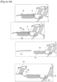
- THE figures 4a to 4d And 5 illustrate steps of a maintenance process for the turbomachine 10.
- the fan module including the fan 14 and the rotor 75a of the electrical machine 70 is removed by axial translation upstream.
- the cover 75b can then be removed by axial translation towards upstream ( figures 4c And 5 ).
- the assembly formed by the ferrules 64-68 and the IGV 52 is then removed by axial translation upstream ( 4d figures And 5 ).
- the next step consists of separating the flange 76 from the bearing support 62 and the inlet casing 40, in order to be able to remove the module M, the cover 75b of which has already been removed.
- FIG. 6 shows a section of an electrical harness 82 which generally has a generally circular shape and comprises a conductive core 82a formed by a strand of cables and an insulating outer sheath 82b.
- FIG 7 shows an example of production of a bar 80, which comprises a body conductor 80a preferably having a polygonal shape and for example rectangular in section. The bar 80 further comprises an insulating external sheath 80b.
- This invention could be applied to any turbomachine equipped with an electric machine upstream of a structural casing of the inlet casing type or other.
Landscapes
- Engineering & Computer Science (AREA)
- Mechanical Engineering (AREA)
- General Engineering & Computer Science (AREA)
- Physics & Mathematics (AREA)
- Fluid Mechanics (AREA)
- Structures Of Non-Positive Displacement Pumps (AREA)
- Connection Of Motors, Electrical Generators, Mechanical Devices, And The Like (AREA)
- Motor Or Generator Frames (AREA)
- Motor Or Generator Cooling System (AREA)
Claims (12)
- Elektrisches Modul (M) für eine Turbomaschine (10) eines Luftfahrzeugs, wobei dieses Modul aufweist:- einen Stator (70b) einer elektrischen Maschine (70), wobei dieser Stator eine ringförmige Form um eine Achse (A) aufweist und dazu bestimmt ist, einen Rotor (70a) der elektrischen Maschine zu umgeben,- ein ringförmiges Trägerelement (74) des Stators, wobei dieses Element eine äußere ringförmige Oberfläche (74a) aufweist, die konfiguriert ist, um von einem Gasstrom (F) der Turbomaschine überstrichen zu werden, zur Kühlung durch Leitung des Stators, dadurch gekennzeichnet, dass das ringförmige Element (74) umfasst:- einen ringförmigen Träger (75a), der mindestens einen Teil des Stators umgibt und bedeckt und der am äußeren Umfang des Stators befestigt ist, wobei dieser Träger mindestens einen Flansch (76) zur Befestigung an einem Organ der Turbomaschine umfasst, wobei sich dieser Flansch am stromabwärtigen Ende des Stators befindet, und- eine ringförmige Haube (75b), die mindestens einen Teil des Trägers (75a) umgibt und bedeckt und die die Oberfläche (74a) umfasst, die von dem Gasstrom (F) überstrichen wird.
- Modul (M) nach Anspruch 1, wobei der Träger (75a) eine zylindrische Wand (75ab) umfasst, die den Stator (70b) bedeckt und durch ihr stromabwärtiges Ende mit dem Flansch (76) verbunden ist, der im Querschnitt eine allgemeine U-Form aufweist, um einen ringförmigen Raum (X) für den elektrischen Anschluss des Stators zu definieren.
- Modul (M) nach Anspruch 1 oder 2, wobei die Haube (75b) an einem stromaufwärtigen Ende eine zylindrische innere Oberfläche (75ba) umfasst, die konfiguriert ist, um mit ringförmigen Lippen (72e) einer Labyrinthdichtung zusammenzuwirken.
- Modul (M) nach einem der vorstehenden Ansprüche, wobei sich die von dem Gasstrom (F) überstrichene Oberfläche (74a) über die gesamte längliche Ausdehnung der Haube (75b) erstreckt.
- Modul (M) nach einem der vorstehenden Ansprüche, wobei die Haube (75b) Öffnungen (75bb) umfasst, die im Wesentlichen radial zur Achse (A) gerichtet sind, wobei diese Öffnungen mit im Träger (75a) gebildeten Gewindelöchern (75ac) ausgerichtet sind, wobei Schrauben (77) konfiguriert sind, um in die Öffnungen (75bb) und die Löchern (75ac) zur Befestigung der Haube am Träger eingeschraubt zu werden.
- Modul (M) nach einem der vorstehenden Ansprüche, wobei die Haube (75b) an ihrem stromabwärtigen Ende eine axial stromabwärts gerichtete ringförmige Nut (74b) zur Aufnahme eines peripheren Randes (64a) eines weiteren Organs der Turbomaschine umfasst.
- Turbomaschine (10) eines Luftfahrzeugs, die aufweist:- einen Gasgenerator (12), der eine Längsachse (A) aufweist,- ein Gebläse (14), das sich an einem stromaufwärtigen Ende des Gasgenerators befindet und zum Drehen um die Achse konfiguriert ist, und- eine allgemein ringförmige elektrische Maschine (70), die koaxial stromabwärts des Gebläses angebracht ist und die einen Rotor (70a), der mit dem Gebläse drehgekoppelt ist, und ein Modul (M) nach einem der vorstehenden Ansprüche umfasst,wobei das Gebläse konfiguriert ist, um einen Hauptgasstrom (F) zu erzeugen, von dem ein Teil in einen ringförmigen Primärstrom des Gasgenerators strömt, um einen Primärstrom (36) zu bilden, und von dem ein anderer Teil in einen ringförmigen Sekundärstrom strömt, der sich zwischen dem Gasgenerator und dem Gondelgehäuse erstreckt, um einen Sekundärstrom (38) zu bilden,wobei der Primärstrom durch eine erste und eine zweite ringförmige Hülle (37a, 37b) begrenzt ist, die koaxial zum Gasgenerator sind, wobei der Primärstrom von Armen, als IGV (52) bezeichnet, zur Verbindung der ersten und der zweiten Hülle sowie von rohrförmigen Armen (42) eines Eingangsgehäuses, das sich stromabwärts der IGV befindet, durchquert wird,wobei der Gasgenerator eine dritte ringförmige Hülle (39) aufweist, die die zweite Hülle koaxial umgibt,wobei die zweite und dritte Hülle (37b, 39) an ihren stromaufwärtigen Enden miteinander verbunden sind, um einen ringförmigen Schnabel (34) zur Trennung des Primär- und Sekundärstroms (36, 38) zu bilden.
- Turbomaschine (10) nach Anspruch 7, wobei die IGV (52) einstückig mit ringförmigen Abschnitten der ersten, zweiten und dritten Hülle (37a, 37b, 39) gebildet sind, wobei diese Einheit konfiguriert ist, um an dem Eingangsgehäuse (40) befestigt zu werden.
- Turbomaschine (10) nach Anspruch 7 oder 8, wobei die Einheit an ihrem äußeren Umfang einen ringförmigen Flansch (79) zur Befestigung am Eingangsgehäuse (40) und an ihrem inneren Umfang ringförmige Ränder, jeweils stromaufwärts (64a) und stromabwärts (64b), zur Auflage und/oder zum Eingriff umfasst.
- Turbomaschine (10) nach einem der Ansprüche 7 bis 9, wobei die elektrische Maschine (70) und das Eingangsgehäuse (40) an einem ringförmigen Lagerträger (62) des Gasgenerators (12) befestigt sind, wobei der Flansch (76) auf den Lagerträger und/oder das Gehäuse aufgebracht und daran befestigt ist.
- Turbomaschine nach einem der Ansprüche 7 bis 10, wobei sie ein Gondelgehäuse (16) umfasst, das den Gasgenerator (12) umgibt, sowie Schaufeln, als OGV (44) bezeichnet, zur Verbindung des Gondelgehäuses mit der dritten ringförmigen Hülle (39).
- Verfahren zur Wartung einer Turbomaschine (10) nach einem der Ansprüche 8 bis 10, umfassend die Schritte, die bestehen aus:- Ausbauen und Entnehmen des Rotors (70a) von der elektrischen Maschine (70),- Ausbauen und Entnehmen der Haube (75b) vom Rest des elektrischen Moduls (70),- Ausbauen und Entnehmen der Einheit (37a, 37b, 39, 52),- Ausbauen und Entnehmen des Rests des elektrischen Moduls.
Applications Claiming Priority (2)
| Application Number | Priority Date | Filing Date | Title |
|---|---|---|---|
| FR1913668A FR3103852B1 (fr) | 2019-12-03 | 2019-12-03 | Module electrique pour une turbomachine d’aeronef |
| PCT/FR2020/052158 WO2021111060A1 (fr) | 2019-12-03 | 2020-11-24 | Module electrique pour une turbomachine d'aeronef |
Publications (2)
| Publication Number | Publication Date |
|---|---|
| EP4069948A1 EP4069948A1 (de) | 2022-10-12 |
| EP4069948B1 true EP4069948B1 (de) | 2023-09-13 |
Family
ID=69191045
Family Applications (1)
| Application Number | Title | Priority Date | Filing Date |
|---|---|---|---|
| EP20820507.0A Active EP4069948B1 (de) | 2019-12-03 | 2020-11-24 | Elektrisches modul für eine turbomaschine eines flugzeugs |
Country Status (5)
| Country | Link |
|---|---|
| US (1) | US12180847B2 (de) |
| EP (1) | EP4069948B1 (de) |
| CN (1) | CN114761668B (de) |
| FR (1) | FR3103852B1 (de) |
| WO (1) | WO2021111060A1 (de) |
Families Citing this family (3)
| Publication number | Priority date | Publication date | Assignee | Title |
|---|---|---|---|---|
| FR3103851B1 (fr) * | 2019-12-03 | 2021-11-05 | Safran Aircraft Engines | Barre rigide pour le raccordement electrique d’une machine dans une turbomachine d’aeronef |
| FR3108140B1 (fr) * | 2020-03-10 | 2022-05-13 | Safran Aircraft Engines | Module de turbomachine equipe d’un rotor de machine electrique |
| FR3114351B1 (fr) * | 2020-09-18 | 2022-08-12 | Safran Aircraft Engines | Raccordement electrique d’une machine electrique dans une turbomachine d’aeronef |
Family Cites Families (22)
| Publication number | Priority date | Publication date | Assignee | Title |
|---|---|---|---|---|
| GB1041587A (en) * | 1962-08-27 | 1966-09-07 | Bristol Siddeley Engines Ltd | Improvements in gas turbine engines |
| GB1141001A (en) * | 1965-03-03 | 1969-01-22 | Rolls Royce | Improvements in gas turbine engines |
| US5118253A (en) * | 1990-09-12 | 1992-06-02 | United Technologies Corporation | Compressor case construction with backbone |
| US5237817A (en) * | 1992-02-19 | 1993-08-24 | Sundstrand Corporation | Gas turbine engine having low cost speed reduction drive |
| FR2842565B1 (fr) | 2002-07-17 | 2005-01-28 | Snecma Moteurs | Demarreur-generateur integre pour turbomachine |
| WO2006059971A2 (en) * | 2004-12-01 | 2006-06-08 | United Technologies Corporation | Tip turbine engine integral fan, combustor, and turbine case |
| FR2896537B1 (fr) | 2006-01-24 | 2011-07-29 | Snecma | Turbomachine a generateur-demarreur integre |
| FR2922265B1 (fr) | 2007-10-12 | 2013-11-22 | Snecma | Turboreacteur incorporant un generateur de courant electrique. |
| NL2003264C2 (en) * | 2009-07-23 | 2011-01-25 | Micro Turbine Technology B V | Method for manufacturing a micro gas turbine. |
| US9181815B2 (en) * | 2012-05-02 | 2015-11-10 | United Technologies Corporation | Shaped rim cavity wing surface |
| US20160195015A1 (en) * | 2012-12-28 | 2016-07-07 | United Technologies Corporation | Gas turbine engine nosecone attachment structure |
| WO2014150377A1 (en) * | 2013-03-15 | 2014-09-25 | Embry-Riddle Aeronautical University, Inc. | Electrically coupled counter-rotation for gas turbine compressors |
| FR3033179B1 (fr) * | 2015-02-26 | 2018-07-27 | Safran Aircraft Engines | Assemblage d'une plateforme rapportee d'aube de soufflante sur un disque de soufflante |
| FR3039225B1 (fr) * | 2015-07-20 | 2017-07-21 | Snecma | Turbomachine, telle par exemple qu'un turboreacteur d'avion |
| FR3039216B1 (fr) * | 2015-07-22 | 2019-12-20 | Safran Aircraft Engines | Ensemble propulsif pour aeronef comportant un inverseur de poussee |
| EP3246526B1 (de) * | 2016-05-18 | 2021-03-24 | Rolls-Royce Corporation | Steuerung eines niedrigdruckwellengenerators für einen gasturbinenmotor |
| US10801410B2 (en) * | 2018-04-12 | 2020-10-13 | Raytheon Technologies Corporation | Thermal management of tail cone mounted generator |
| US11156128B2 (en) * | 2018-08-22 | 2021-10-26 | General Electric Company | Embedded electric machine |
| FR3087819B1 (fr) * | 2018-10-26 | 2020-11-13 | Safran Aircraft Engines | Turbomachine d'aeronef equipee d'une machine electrique |
| FR3087820B1 (fr) * | 2018-10-26 | 2020-10-16 | Safran Aircraft Engines | Turbomachine d'aeronef equipee d'une machine electrique |
| FR3103851B1 (fr) * | 2019-12-03 | 2021-11-05 | Safran Aircraft Engines | Barre rigide pour le raccordement electrique d’une machine dans une turbomachine d’aeronef |
| FR3103854B1 (fr) * | 2019-12-03 | 2022-01-28 | Safran Aircraft Engines | Raccordement electrique d’une machine electrique dans une turbomachine d’aeronef |
-
2019
- 2019-12-03 FR FR1913668A patent/FR3103852B1/fr active Active
-
2020
- 2020-11-24 EP EP20820507.0A patent/EP4069948B1/de active Active
- 2020-11-24 CN CN202080083679.9A patent/CN114761668B/zh active Active
- 2020-11-24 US US17/779,203 patent/US12180847B2/en active Active
- 2020-11-24 WO PCT/FR2020/052158 patent/WO2021111060A1/fr not_active Ceased
Also Published As
| Publication number | Publication date |
|---|---|
| WO2021111060A1 (fr) | 2021-06-10 |
| FR3103852A1 (fr) | 2021-06-04 |
| EP4069948A1 (de) | 2022-10-12 |
| US20220403751A1 (en) | 2022-12-22 |
| US12180847B2 (en) | 2024-12-31 |
| CN114761668B (zh) | 2024-05-17 |
| FR3103852B1 (fr) | 2021-10-22 |
| CN114761668A (zh) | 2022-07-15 |
Similar Documents
| Publication | Publication Date | Title |
|---|---|---|
| EP4069944B1 (de) | Elektrische verbindung einer elektrischen maschine in einem flugzeugtriebwerk | |
| EP3870810B1 (de) | Gebläsemodul ausgerüstet mit einer elektrischen maschine für eine turbomaschine eines luftfahrzeugs | |
| EP3155234B1 (de) | Turbinenmotor mit einem antriebssystem für eine vorrichtung wie ein hilfsaggregatgehäuse | |
| EP3377732B1 (de) | Vorderer teil einer turbomaschine | |
| WO2020084241A1 (fr) | Turbomachine d'aeronef equipee d'une machine electrique | |
| EP4069948B1 (de) | Elektrisches modul für eine turbomaschine eines flugzeugs | |
| FR3054264A1 (fr) | Turbomachine a reducteur a train epicycloidal | |
| WO2020084219A1 (fr) | Turbomachine d'aeronef equipee d'une machine electrique | |
| EP4069946B1 (de) | Elektrische verbindung für eine elektrische maschine in einem flugzeugturbinenmotor | |
| EP4069945B1 (de) | Starre stange zur elektrischen verbindung einer maschine in einem flugtriebwerk | |
| EP3870811B1 (de) | Turbomaschine mit einer elektrischen maschine mit einem an dem gebläse angebundenen ring | |
| EP3870812B1 (de) | Flugzeugturbomaschine ausgerüstet mit einer elektrischen maschine | |
| EP4214403B1 (de) | Elektrische verbindung einer elektrischen maschine in einem flugzeugturbinentriebwerk | |
| EP3810911B1 (de) | Flugzeugturbinentriebwerk mit mindestens zwei körpern und vorrichtung zur energieversorgung | |
| FR3108140A1 (fr) | Module de turbomachine equipe d’un rotor de machine electrique |
Legal Events
| Date | Code | Title | Description |
|---|---|---|---|
| STAA | Information on the status of an ep patent application or granted ep patent |
Free format text: STATUS: UNKNOWN |
|
| STAA | Information on the status of an ep patent application or granted ep patent |
Free format text: STATUS: THE INTERNATIONAL PUBLICATION HAS BEEN MADE |
|
| PUAI | Public reference made under article 153(3) epc to a published international application that has entered the european phase |
Free format text: ORIGINAL CODE: 0009012 |
|
| STAA | Information on the status of an ep patent application or granted ep patent |
Free format text: STATUS: REQUEST FOR EXAMINATION WAS MADE |
|
| 17P | Request for examination filed |
Effective date: 20220510 |
|
| AK | Designated contracting states |
Kind code of ref document: A1 Designated state(s): AL AT BE BG CH CY CZ DE DK EE ES FI FR GB GR HR HU IE IS IT LI LT LU LV MC MK MT NL NO PL PT RO RS SE SI SK SM TR |
|
| DAV | Request for validation of the european patent (deleted) | ||
| DAX | Request for extension of the european patent (deleted) | ||
| GRAP | Despatch of communication of intention to grant a patent |
Free format text: ORIGINAL CODE: EPIDOSNIGR1 |
|
| STAA | Information on the status of an ep patent application or granted ep patent |
Free format text: STATUS: GRANT OF PATENT IS INTENDED |
|
| GRAS | Grant fee paid |
Free format text: ORIGINAL CODE: EPIDOSNIGR3 |
|
| GRAA | (expected) grant |
Free format text: ORIGINAL CODE: 0009210 |
|
| STAA | Information on the status of an ep patent application or granted ep patent |
Free format text: STATUS: THE PATENT HAS BEEN GRANTED |
|
| INTG | Intention to grant announced |
Effective date: 20230720 |
|
| AK | Designated contracting states |
Kind code of ref document: B1 Designated state(s): AL AT BE BG CH CY CZ DE DK EE ES FI FR GB GR HR HU IE IS IT LI LT LU LV MC MK MT NL NO PL PT RO RS SE SI SK SM TR |
|
| REG | Reference to a national code |
Ref country code: CH Ref legal event code: EP |
|
| REG | Reference to a national code |
Ref country code: DE Ref legal event code: R096 Ref document number: 602020017764 Country of ref document: DE |
|
| REG | Reference to a national code |
Ref country code: IE Ref legal event code: FG4D Free format text: LANGUAGE OF EP DOCUMENT: FRENCH |
|
| REG | Reference to a national code |
Ref country code: LT Ref legal event code: MG9D |
|
| REG | Reference to a national code |
Ref country code: NL Ref legal event code: MP Effective date: 20230913 |
|
| PG25 | Lapsed in a contracting state [announced via postgrant information from national office to epo] |
Ref country code: GR Free format text: LAPSE BECAUSE OF FAILURE TO SUBMIT A TRANSLATION OF THE DESCRIPTION OR TO PAY THE FEE WITHIN THE PRESCRIBED TIME-LIMIT Effective date: 20231214 |
|
| PG25 | Lapsed in a contracting state [announced via postgrant information from national office to epo] |
Ref country code: SE Free format text: LAPSE BECAUSE OF FAILURE TO SUBMIT A TRANSLATION OF THE DESCRIPTION OR TO PAY THE FEE WITHIN THE PRESCRIBED TIME-LIMIT Effective date: 20230913 Ref country code: RS Free format text: LAPSE BECAUSE OF FAILURE TO SUBMIT A TRANSLATION OF THE DESCRIPTION OR TO PAY THE FEE WITHIN THE PRESCRIBED TIME-LIMIT Effective date: 20230913 Ref country code: NO Free format text: LAPSE BECAUSE OF FAILURE TO SUBMIT A TRANSLATION OF THE DESCRIPTION OR TO PAY THE FEE WITHIN THE PRESCRIBED TIME-LIMIT Effective date: 20231213 Ref country code: LV Free format text: LAPSE BECAUSE OF FAILURE TO SUBMIT A TRANSLATION OF THE DESCRIPTION OR TO PAY THE FEE WITHIN THE PRESCRIBED TIME-LIMIT Effective date: 20230913 Ref country code: LT Free format text: LAPSE BECAUSE OF FAILURE TO SUBMIT A TRANSLATION OF THE DESCRIPTION OR TO PAY THE FEE WITHIN THE PRESCRIBED TIME-LIMIT Effective date: 20230913 Ref country code: HR Free format text: LAPSE BECAUSE OF FAILURE TO SUBMIT A TRANSLATION OF THE DESCRIPTION OR TO PAY THE FEE WITHIN THE PRESCRIBED TIME-LIMIT Effective date: 20230913 Ref country code: GR Free format text: LAPSE BECAUSE OF FAILURE TO SUBMIT A TRANSLATION OF THE DESCRIPTION OR TO PAY THE FEE WITHIN THE PRESCRIBED TIME-LIMIT Effective date: 20231214 Ref country code: FI Free format text: LAPSE BECAUSE OF FAILURE TO SUBMIT A TRANSLATION OF THE DESCRIPTION OR TO PAY THE FEE WITHIN THE PRESCRIBED TIME-LIMIT Effective date: 20230913 |
|
| REG | Reference to a national code |
Ref country code: AT Ref legal event code: MK05 Ref document number: 1611503 Country of ref document: AT Kind code of ref document: T Effective date: 20230913 |
|
| PG25 | Lapsed in a contracting state [announced via postgrant information from national office to epo] |
Ref country code: NL Free format text: LAPSE BECAUSE OF FAILURE TO SUBMIT A TRANSLATION OF THE DESCRIPTION OR TO PAY THE FEE WITHIN THE PRESCRIBED TIME-LIMIT Effective date: 20230913 |
|
| PG25 | Lapsed in a contracting state [announced via postgrant information from national office to epo] |
Ref country code: IS Free format text: LAPSE BECAUSE OF FAILURE TO SUBMIT A TRANSLATION OF THE DESCRIPTION OR TO PAY THE FEE WITHIN THE PRESCRIBED TIME-LIMIT Effective date: 20240113 |
|
| PG25 | Lapsed in a contracting state [announced via postgrant information from national office to epo] |
Ref country code: AT Free format text: LAPSE BECAUSE OF FAILURE TO SUBMIT A TRANSLATION OF THE DESCRIPTION OR TO PAY THE FEE WITHIN THE PRESCRIBED TIME-LIMIT Effective date: 20230913 |
|
| PG25 | Lapsed in a contracting state [announced via postgrant information from national office to epo] |
Ref country code: ES Free format text: LAPSE BECAUSE OF FAILURE TO SUBMIT A TRANSLATION OF THE DESCRIPTION OR TO PAY THE FEE WITHIN THE PRESCRIBED TIME-LIMIT Effective date: 20230913 |
|
| PG25 | Lapsed in a contracting state [announced via postgrant information from national office to epo] |
Ref country code: SM Free format text: LAPSE BECAUSE OF FAILURE TO SUBMIT A TRANSLATION OF THE DESCRIPTION OR TO PAY THE FEE WITHIN THE PRESCRIBED TIME-LIMIT Effective date: 20230913 Ref country code: RO Free format text: LAPSE BECAUSE OF FAILURE TO SUBMIT A TRANSLATION OF THE DESCRIPTION OR TO PAY THE FEE WITHIN THE PRESCRIBED TIME-LIMIT Effective date: 20230913 Ref country code: IS Free format text: LAPSE BECAUSE OF FAILURE TO SUBMIT A TRANSLATION OF THE DESCRIPTION OR TO PAY THE FEE WITHIN THE PRESCRIBED TIME-LIMIT Effective date: 20240113 Ref country code: ES Free format text: LAPSE BECAUSE OF FAILURE TO SUBMIT A TRANSLATION OF THE DESCRIPTION OR TO PAY THE FEE WITHIN THE PRESCRIBED TIME-LIMIT Effective date: 20230913 Ref country code: EE Free format text: LAPSE BECAUSE OF FAILURE TO SUBMIT A TRANSLATION OF THE DESCRIPTION OR TO PAY THE FEE WITHIN THE PRESCRIBED TIME-LIMIT Effective date: 20230913 Ref country code: CZ Free format text: LAPSE BECAUSE OF FAILURE TO SUBMIT A TRANSLATION OF THE DESCRIPTION OR TO PAY THE FEE WITHIN THE PRESCRIBED TIME-LIMIT Effective date: 20230913 Ref country code: AT Free format text: LAPSE BECAUSE OF FAILURE TO SUBMIT A TRANSLATION OF THE DESCRIPTION OR TO PAY THE FEE WITHIN THE PRESCRIBED TIME-LIMIT Effective date: 20230913 Ref country code: SK Free format text: LAPSE BECAUSE OF FAILURE TO SUBMIT A TRANSLATION OF THE DESCRIPTION OR TO PAY THE FEE WITHIN THE PRESCRIBED TIME-LIMIT Effective date: 20230913 Ref country code: PT Free format text: LAPSE BECAUSE OF FAILURE TO SUBMIT A TRANSLATION OF THE DESCRIPTION OR TO PAY THE FEE WITHIN THE PRESCRIBED TIME-LIMIT Effective date: 20240115 |
|
| PG25 | Lapsed in a contracting state [announced via postgrant information from national office to epo] |
Ref country code: PL Free format text: LAPSE BECAUSE OF FAILURE TO SUBMIT A TRANSLATION OF THE DESCRIPTION OR TO PAY THE FEE WITHIN THE PRESCRIBED TIME-LIMIT Effective date: 20230913 Ref country code: IT Free format text: LAPSE BECAUSE OF FAILURE TO SUBMIT A TRANSLATION OF THE DESCRIPTION OR TO PAY THE FEE WITHIN THE PRESCRIBED TIME-LIMIT Effective date: 20230913 |
|
| REG | Reference to a national code |
Ref country code: DE Ref legal event code: R097 Ref document number: 602020017764 Country of ref document: DE |
|
| REG | Reference to a national code |
Ref country code: CH Ref legal event code: PL |
|
| PG25 | Lapsed in a contracting state [announced via postgrant information from national office to epo] |
Ref country code: MC Free format text: LAPSE BECAUSE OF FAILURE TO SUBMIT A TRANSLATION OF THE DESCRIPTION OR TO PAY THE FEE WITHIN THE PRESCRIBED TIME-LIMIT Effective date: 20230913 |
|
| PG25 | Lapsed in a contracting state [announced via postgrant information from national office to epo] |
Ref country code: DK Free format text: LAPSE BECAUSE OF FAILURE TO SUBMIT A TRANSLATION OF THE DESCRIPTION OR TO PAY THE FEE WITHIN THE PRESCRIBED TIME-LIMIT Effective date: 20230913 |
|
| PG25 | Lapsed in a contracting state [announced via postgrant information from national office to epo] |
Ref country code: LU Free format text: LAPSE BECAUSE OF NON-PAYMENT OF DUE FEES Effective date: 20231124 |
|
| PG25 | Lapsed in a contracting state [announced via postgrant information from national office to epo] |
Ref country code: CH Free format text: LAPSE BECAUSE OF NON-PAYMENT OF DUE FEES Effective date: 20231130 |
|
| PLBE | No opposition filed within time limit |
Free format text: ORIGINAL CODE: 0009261 |
|
| STAA | Information on the status of an ep patent application or granted ep patent |
Free format text: STATUS: NO OPPOSITION FILED WITHIN TIME LIMIT |
|
| PG25 | Lapsed in a contracting state [announced via postgrant information from national office to epo] |
Ref country code: MC Free format text: LAPSE BECAUSE OF FAILURE TO SUBMIT A TRANSLATION OF THE DESCRIPTION OR TO PAY THE FEE WITHIN THE PRESCRIBED TIME-LIMIT Effective date: 20230913 Ref country code: DK Free format text: LAPSE BECAUSE OF FAILURE TO SUBMIT A TRANSLATION OF THE DESCRIPTION OR TO PAY THE FEE WITHIN THE PRESCRIBED TIME-LIMIT Effective date: 20230913 Ref country code: CH Free format text: LAPSE BECAUSE OF NON-PAYMENT OF DUE FEES Effective date: 20231130 Ref country code: LU Free format text: LAPSE BECAUSE OF NON-PAYMENT OF DUE FEES Effective date: 20231124 |
|
| REG | Reference to a national code |
Ref country code: BE Ref legal event code: MM Effective date: 20231130 |
|
| 26N | No opposition filed |
Effective date: 20240614 |
|
| REG | Reference to a national code |
Ref country code: IE Ref legal event code: MM4A |
|
| PG25 | Lapsed in a contracting state [announced via postgrant information from national office to epo] |
Ref country code: IE Free format text: LAPSE BECAUSE OF NON-PAYMENT OF DUE FEES Effective date: 20231124 |
|
| PG25 | Lapsed in a contracting state [announced via postgrant information from national office to epo] |
Ref country code: BE Free format text: LAPSE BECAUSE OF NON-PAYMENT OF DUE FEES Effective date: 20231130 |
|
| PG25 | Lapsed in a contracting state [announced via postgrant information from national office to epo] |
Ref country code: SI Free format text: LAPSE BECAUSE OF FAILURE TO SUBMIT A TRANSLATION OF THE DESCRIPTION OR TO PAY THE FEE WITHIN THE PRESCRIBED TIME-LIMIT Effective date: 20230913 |
|
| PG25 | Lapsed in a contracting state [announced via postgrant information from national office to epo] |
Ref country code: SI Free format text: LAPSE BECAUSE OF FAILURE TO SUBMIT A TRANSLATION OF THE DESCRIPTION OR TO PAY THE FEE WITHIN THE PRESCRIBED TIME-LIMIT Effective date: 20230913 Ref country code: IE Free format text: LAPSE BECAUSE OF NON-PAYMENT OF DUE FEES Effective date: 20231124 Ref country code: BE Free format text: LAPSE BECAUSE OF NON-PAYMENT OF DUE FEES Effective date: 20231130 |
|
| PG25 | Lapsed in a contracting state [announced via postgrant information from national office to epo] |
Ref country code: BG Free format text: LAPSE BECAUSE OF FAILURE TO SUBMIT A TRANSLATION OF THE DESCRIPTION OR TO PAY THE FEE WITHIN THE PRESCRIBED TIME-LIMIT Effective date: 20230913 |
|
| PG25 | Lapsed in a contracting state [announced via postgrant information from national office to epo] |
Ref country code: BG Free format text: LAPSE BECAUSE OF FAILURE TO SUBMIT A TRANSLATION OF THE DESCRIPTION OR TO PAY THE FEE WITHIN THE PRESCRIBED TIME-LIMIT Effective date: 20230913 |
|
| PG25 | Lapsed in a contracting state [announced via postgrant information from national office to epo] |
Ref country code: CY Free format text: LAPSE BECAUSE OF FAILURE TO SUBMIT A TRANSLATION OF THE DESCRIPTION OR TO PAY THE FEE WITHIN THE PRESCRIBED TIME-LIMIT; INVALID AB INITIO Effective date: 20201124 |
|
| PG25 | Lapsed in a contracting state [announced via postgrant information from national office to epo] |
Ref country code: HU Free format text: LAPSE BECAUSE OF FAILURE TO SUBMIT A TRANSLATION OF THE DESCRIPTION OR TO PAY THE FEE WITHIN THE PRESCRIBED TIME-LIMIT; INVALID AB INITIO Effective date: 20201124 |
|
| PG25 | Lapsed in a contracting state [announced via postgrant information from national office to epo] |
Ref country code: TR Free format text: LAPSE BECAUSE OF FAILURE TO SUBMIT A TRANSLATION OF THE DESCRIPTION OR TO PAY THE FEE WITHIN THE PRESCRIBED TIME-LIMIT Effective date: 20230913 |
|
| PGFP | Annual fee paid to national office [announced via postgrant information from national office to epo] |
Ref country code: DE Payment date: 20251118 Year of fee payment: 6 |
|
| PGFP | Annual fee paid to national office [announced via postgrant information from national office to epo] |
Ref country code: GB Payment date: 20251125 Year of fee payment: 6 |
|
| PGFP | Annual fee paid to national office [announced via postgrant information from national office to epo] |
Ref country code: FR Payment date: 20251125 Year of fee payment: 6 |