EP3870833B1 - Verbesserter hydraulischer motor für ein lenkbares rad eines fahrzeugs - Google Patents
Verbesserter hydraulischer motor für ein lenkbares rad eines fahrzeugs Download PDFInfo
- Publication number
- EP3870833B1 EP3870833B1 EP19809134.0A EP19809134A EP3870833B1 EP 3870833 B1 EP3870833 B1 EP 3870833B1 EP 19809134 A EP19809134 A EP 19809134A EP 3870833 B1 EP3870833 B1 EP 3870833B1
- Authority
- EP
- European Patent Office
- Prior art keywords
- rotation
- axis
- rolling
- element bearing
- proximal
- Prior art date
- Legal status (The legal status is an assumption and is not a legal conclusion. Google has not performed a legal analysis and makes no representation as to the accuracy of the status listed.)
- Active
Links
Images


Classifications
-
- F—MECHANICAL ENGINEERING; LIGHTING; HEATING; WEAPONS; BLASTING
- F03—MACHINES OR ENGINES FOR LIQUIDS; WIND, SPRING, OR WEIGHT MOTORS; PRODUCING MECHANICAL POWER OR A REACTIVE PROPULSIVE THRUST, NOT OTHERWISE PROVIDED FOR
- F03C—POSITIVE-DISPLACEMENT ENGINES DRIVEN BY LIQUIDS
- F03C1/00—Reciprocating-piston liquid engines
- F03C1/02—Reciprocating-piston liquid engines with multiple-cylinders, characterised by the number or arrangement of cylinders
- F03C1/04—Reciprocating-piston liquid engines with multiple-cylinders, characterised by the number or arrangement of cylinders with cylinders in star or fan arrangement
- F03C1/047—Reciprocating-piston liquid engines with multiple-cylinders, characterised by the number or arrangement of cylinders with cylinders in star or fan arrangement the pistons co-operating with an actuated element at the outer ends of the cylinders
-
- B—PERFORMING OPERATIONS; TRANSPORTING
- B60—VEHICLES IN GENERAL
- B60B—VEHICLE WHEELS; CASTORS; AXLES FOR WHEELS OR CASTORS; INCREASING WHEEL ADHESION
- B60B35/00—Axle units; Parts thereof ; Arrangements for lubrication of axles
- B60B35/12—Torque-transmitting axles
- B60B35/18—Arrangement of bearings
-
- B—PERFORMING OPERATIONS; TRANSPORTING
- B60—VEHICLES IN GENERAL
- B60K—ARRANGEMENT OR MOUNTING OF PROPULSION UNITS OR OF TRANSMISSIONS IN VEHICLES; ARRANGEMENT OR MOUNTING OF PLURAL DIVERSE PRIME-MOVERS IN VEHICLES; AUXILIARY DRIVES FOR VEHICLES; INSTRUMENTATION OR DASHBOARDS FOR VEHICLES; ARRANGEMENTS IN CONNECTION WITH COOLING, AIR INTAKE, GAS EXHAUST OR FUEL SUPPLY OF PROPULSION UNITS IN VEHICLES
- B60K7/00—Disposition of motor in, or adjacent to, traction wheel
- B60K7/0015—Disposition of motor in, or adjacent to, traction wheel the motor being hydraulic
-
- F—MECHANICAL ENGINEERING; LIGHTING; HEATING; WEAPONS; BLASTING
- F03—MACHINES OR ENGINES FOR LIQUIDS; WIND, SPRING, OR WEIGHT MOTORS; PRODUCING MECHANICAL POWER OR A REACTIVE PROPULSIVE THRUST, NOT OTHERWISE PROVIDED FOR
- F03C—POSITIVE-DISPLACEMENT ENGINES DRIVEN BY LIQUIDS
- F03C1/00—Reciprocating-piston liquid engines
- F03C1/02—Reciprocating-piston liquid engines with multiple-cylinders, characterised by the number or arrangement of cylinders
- F03C1/04—Reciprocating-piston liquid engines with multiple-cylinders, characterised by the number or arrangement of cylinders with cylinders in star or fan arrangement
- F03C1/0403—Details, component parts specially adapted of such engines
- F03C1/0435—Particularities relating to the distribution members
-
- B—PERFORMING OPERATIONS; TRANSPORTING
- B60—VEHICLES IN GENERAL
- B60K—ARRANGEMENT OR MOUNTING OF PROPULSION UNITS OR OF TRANSMISSIONS IN VEHICLES; ARRANGEMENT OR MOUNTING OF PLURAL DIVERSE PRIME-MOVERS IN VEHICLES; AUXILIARY DRIVES FOR VEHICLES; INSTRUMENTATION OR DASHBOARDS FOR VEHICLES; ARRANGEMENTS IN CONNECTION WITH COOLING, AIR INTAKE, GAS EXHAUST OR FUEL SUPPLY OF PROPULSION UNITS IN VEHICLES
- B60K7/00—Disposition of motor in, or adjacent to, traction wheel
- B60K2007/0038—Disposition of motor in, or adjacent to, traction wheel the motor moving together with the wheel axle
Definitions
- the present invention relates to hydraulic machines, and more specifically to an improved hydraulic machine structure.
- Hydraulic machines and in particular the hydraulic motors used for driving the steered wheels of a vehicle, must meet several specific constraints in terms of compactness, and must be able to be associated with means for fixing a wheel.
- Hydraulic motors are thus known as presented in the document EN 2693154 , which has a hydraulic motor driving a vehicle steering wheel.
- the motor as presented is rotatably mounted by means of bearings arranged in an O arrangement between the wheel spindle and the hydraulic motor.
- the elements forming the hydraulic motor are arranged between the pivot axis and the bearings.
- Another hydraulic motor is for example known from the document EP 3 012 141 A1 .
- the present invention thus aims to respond at least partially to these problems.
- the distributor or more precisely the core of the distributor, is positioned between the cylinder block and the distal bearing along the second axis of rotation.
- the projections of the pivot element and of the distal bearing in view along a plane defined by the second axis of rotation and parallel to the first axis of rotation are at least partially superimposed.
- the pivot element comprises a plurality of hydraulic conduits arranged within it, so as to allow a supply of hydraulic fluid to the distributor.
- the proximal bearing (5A) and the distal bearing are arranged in an O assembly.
- the cylinder block is then typically configured so as to exert a force tending to move the shaft from its distal end towards its proximal end, and in which the distal bearing comprises an inner ring and an outer ring between which are arranged a plurality frustoconical rollers, the outer ring of the distal bearing being mounted in abutment against a casing segment, so as to oppose said movement of the shaft.
- proximal bearing and the distal bearing are arranged in an X arrangement.
- the proximal bearing then typically comprises an inner ring and an outer ring between which are arranged a plurality of frustoconical rollers and in which the cylinder block is configured so as to exert a force tending to move the inner ring of the proximal bearing in a direction ranging from the distal end towards the proximal end of the shaft, the outer ring of the proximal bearing being mounted in abutment against a casing segment, so as to oppose said displacement.
- This presentation also relates to a vehicle comprising an axle and having two steered wheels, said two steered wheels each being mounted on an assembly as defined above integral with the axle.
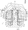
- a first embodiment of the invention is described below with reference to the figure 1 and 2 .
- FIGS. 1 and 2 show a system comprising a hydraulic device 3 coupled to an axle 1 via a pivot 2.
- the hydraulic device 3 is mounted to move relative to the axle 1 along a first axis of rotation X-X by through pivot 2.
- Axle 1 typically comprises two arms 12 defining a general C shape and forming a support for pivot 2.
- the hydraulic apparatus 3 is for example a hydraulic apparatus with radial pistons and multilobe cam.
- the hydraulic device may be an axial piston device, a vane device, an internal or external gear device.
- the hydraulic device 3 also comprises a shaft 4 and a casing 35, sections of which may be formed in particular by the cam 34 and by the timing casing 31b.
- a set of fixed elements or stator and a set of rotating elements or rotor are defined for the hydraulic apparatus 3.
- the rotor includes shaft 4 and cylinder block 32
- the stator includes cam 34, housing 35 and distributor 31.
- connection between the rotor and the stator is made via a bearing 5 comprising here two rolling elements 5A and 5B, here tapered bearings arranged in an O arrangement.
- the bearing 5A is a bearing lubricated with grease and the bearing 5B is a bearing lubricated with oil, in particular the oil of the hydraulic apparatus 3.
- the two bearing elements 5A and B are lubricated by the oil and in particular the oil of the hydraulic device 3.
- the first axis of rotation XX and the second axis of rotation ZZ are not in the same plane. More precisely, if we consider a plane P defined by the second axis of rotation ZZ and parallel to the first axis of rotation XX, the first axis of rotation XX is then outside this plane P, typically offset by a non-zero distance according to a direction perpendicular to the plane P.
- the plane P corresponds to the plane of figure 2 , 4 and 5 .
- This configuration makes it possible to improve the compactness of the assembly, as will be detailed below.
- the hydraulic device 3 typically comprises means configured to allow a vehicle wheel rim and tire to be carried.
- the shaft 4 of the hydraulic device 3 forms a wheel spindle, having a proximal end 4A provided with a portion extending radially and forming a support zone for fixing a rim (not shown).
- the shaft 4 thus forms a wheel spindle comprising a hub 42 at its proximal end 4A for fixing a rim, the opposite end of the shaft 4 here forming a distal end 4B.
- a proximal end 3A of the hydraulic device 3 and a distal end 3B of the hydraulic device 3 are thus generally defined.
- the proximal end 3A of the hydraulic device 3 corresponds to the proximal end 4A of shaft 4, while distal end 3B corresponds to a cover covering distal end 4B of shaft 4.
- pivot 2 connects timing cover 31b (also called timing cover) to axle 1 via two pivot connections 2A and 2B aligned along axis XX on either side of the device hydraulic 3.
- timing cover 31b also called timing cover
- pivot connection is made between the timing cover 31b and a pivot element 2 secured to the axle 1, this pivot element thus being able to be produced with finer manufacturing tolerances than the axle 1.
- One of the pivot links typically comprises ducts forming supply, exhaust and hydraulic drain lines for the hydraulic device 3 made directly in the pivot and connected to the distributor 31 of the hydraulic device 3.
- the other of the pivot connections 2B here the lower pivot connection, may in particular comprise means for forming a pneumatic conduit and/or for measuring the rotation of the pivot 2, for example a rotation sensor, within the pivot, as shown described below.
- the upper pivot link 2A can comprise means for forming a pneumatic conduit and/or for measuring the rotation of the pivot 2, for example a rotation sensor
- the lower pivot linkage 2B comprises conduits forming supply lines hydraulics for the hydraulic apparatus 3, the operation remaining unchanged.
- the pivot connection considered allows relative rotation of the hydraulic apparatus 3 and of the axle 1 along the first axis of rotation X-X.
- the two bearings 5A and 5B will subsequently be referred to as being the proximal bearing 5A and the distal bearing 5B, each being closer to the end of the same name.
- the proximal bearing 5A and the distal bearing 5B are positioned on either side of the cylinder block 32 and of the distributor 31 of the hydraulic device 3, and are arranged in an O assembly as already indicated previously.
- each bearing 5A and 5B comprises an inner ring and an outer ring between which are arranged a plurality of tapered rollers.
- the inner ring is mounted bearing against a shoulder, here formed by the shaft 4, forming a stop in a direction going from the distal end 3B towards the proximal end 3A.
- the outer ring is mounted against a shoulder formed by a segment of the casing 35, forming an abutment in a direction going from the proximal end 3A towards the distal end 3B.
- the inner ring is mounted bearing against a shoulder, here formed by a nut or by an adjustable wedge mounted on the shaft 4, forming a stop in a direction going from the proximal end 3A towards the distal end 3B.
- the outer ring is mounted against a shoulder formed by a segment of the casing 35, forming an abutment in a direction going from the distal end 3B towards the proximal end 3A.
- the proximal bearing 5A and the distal bearing 5B are positioned at least partially on either side of the projection of the first axis of rotation X-X.
- the cylinder block 32 is positioned between the first axis of rotation X-X and the proximal bearing 5A.
- This configuration makes it possible to reconcile a reduced size at the level of the distal part 3B of the hydraulic apparatus 3, while making it possible to propose a shaft 4 which is described as short, that is to say with a reduced distance between the first axis of rotation X-X and the proximal end 4A of the shaft carrying the means configured to make it possible to carry a rim and a vehicle wheel tire, without requiring the size of the hydraulic apparatus 3 to be increased according to the first axis of rotation X-X.
- the bulk at the distal end 3B (which forms what is referred to as the rear, as opposed to the proximal end 3A adapted to carry a tire and which forms the front of the wheel motor) is reduced , which makes it possible to simplify the design of the axle 1 and in particular of the arms 12 of the axle 1 forming a support for the pivot 2, and also to simplify the possible integration of pipes at the rear of the engine, for example pneumatic or hydraulic supply lines if the latter are not made directly within the pivot 2.
- the proximal bearing 5A is typically isolated from the internal volume of the hydraulic apparatus 3 (that is to say from the volume delimited by the casing 35 in which is arranged in particular the cylinder block 32) and the external environment by dynamic sealing means.
- the cylinder block 32 is mounted bearing against an axial abutment formed on the shaft 4 by means of a wedge 43.
- the cylinder block 32 is subjected to a thrust force exerted by the distributor 31 (in the occurrence the core 31a of the distributor 31) resulting from the pressurization of the various ducts of the distributor 31.
- This force is transmitted by the cylinder block 32 to the shaft 4 via the wedge 43 tending to move it in a direction defined by the second axis of rotation Z-Z, from the distal end 4B towards the proximal end 4A.
- the distributor 31 as shown extends on either side of the first axis of rotation X-X in view according to a plane defined by the second axis of rotation Z-Z and the first axis of rotation X-X, and is typically configured so as to extend essentially in the direction of the proximal end 3A of the hydraulic device 3, which results in particular from the position of the cylinder block 32 which is positioned between the distributor 31 and the proximal bearing 5A.
- the fluid supply is here carried out directly through an element of the pivot 2 producing a fluid supply from ducts arranged in the distribution casing 31b as already indicated above.
- FIG. 3 and 4 represent another embodiment of an assembly according to the invention.
- the two rolling elements 5A and 5B are arranged in an X arrangement.
- the inner ring is mounted bearing against a ring resting on the shaft 4, forming a stop in a direction going from the proximal end 3A towards the distal end 3B.
- the outer ring is mounted against a shoulder formed by a segment of the casing 35, forming a abutment in a direction going from the distal end 3B towards the proximal end 3A.
- the inner ring is mounted bearing against a shoulder, here formed by the shaft 4, forming a stop in a direction going from the proximal end 3A towards the distal end 3B.
- the outer ring is mounted against a shoulder formed by a segment of the casing 35, forming an abutment in a direction going from the proximal end 3A towards the distal end 3B.
- the cylinder block 32 is mounted bearing against the inner ring of the proximal bearing 5A.
- the cylinder block 32 is subjected to a thrust force along the second axis of rotation Z-Z in a direction going from the distal end 3B towards the proximal end 3A exerted by the distributor 31 (in this case the core 31a of the distributor 31 ) resulting from the pressurization of the various ducts of the distributor 31.
- This force is transmitted by the cylinder block 32 to the proximal bearing 5A, which will take up this force due to the mounting in X of the bearings 5A and 5B, the proximal bearing 5A will so resume that effort.
- the force tends to move the inner ring of the proximal bearing 5A (and therefore the shaft 4 against which it bears) in this direction going from the distal end 3B towards the proximal end 3A.
- the outer ring of the proximal bearing 5A mounted in abutment against the casing segment 35 opposes this movement.
- the first axis of rotation XX and the second axis of rotation ZZ are not in the same plane. This discrepancy is particularly visible on the picture 3 .
- this embodiment makes it possible to reconcile a reduced size at the level of the distal part 3B of the hydraulic device 3, while making it possible to propose a shaft 4 which is described as short, that is to say with a reduced distance between the first axis of rotation XX and the proximal end 4A of the shaft carrying the means configured to make it possible to carry a rim and a vehicle wheel tire, without needing to increase the size of the hydraulic apparatus 3 along the first axis of rotation XX.
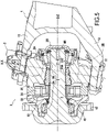
- the figure 5 presents a variant of the embodiment shown in the picture 2 previously described.
- the element 2A of the pivot link 2 has a dimension that is substantially greater than the element 2A of the pivot link 2 shown above with reference to the figure 4 .
- Such a configuration makes it possible to increase the compactness of the system, and/or to offer more volume available for the pivot 2, which can in particular be advantageous when hydraulic or pneumatic conduits are arranged directly in the pivot 2.
- Such a configuration with superposition in the plane P of the projection of the distal bearing 5B and of at least one element of the pivot 2 can also be achieved with bearings forming an X assembly as already presented with reference to the figure 3 and 4 .
Landscapes
- Engineering & Computer Science (AREA)
- Mechanical Engineering (AREA)
- Chemical & Material Sciences (AREA)
- Combustion & Propulsion (AREA)
- General Engineering & Computer Science (AREA)
- Transportation (AREA)
- Hydraulic Motors (AREA)
- Reciprocating Pumps (AREA)
Claims (9)
- Anordnung, umfassend:eine hydraulische Vorrichtung (3), die einen Rotor und einen Stator umfasst, wobei der Rotor in Bezug auf den Stator entlang einer zweiten Rotationsachse (Z-Z) mittels eines proximalen Wälzlagers (5A) und eines distalen Wälzlagers (5B) drehbar angebracht ist, wobei die hydraulische Vorrichtung (3) eine Welle (4), einen mehrlappigen Nocken (34), einen Zylinderblock (32), welcher eine Vielzahl von Aufnahmen aufweist, die jeweils mit einem Kolben (33) versehen sind, der gegenüber dem mehrlappigen Nocken (34) verschieblich angebracht ist, sowie einen Verteiler (31), welcher einen Kern (31a) und ein Verteilergehäuse (31b) umfasst, aufweist,ein Drehgelenkelement (2), das dazu bestimmt ist, an einer Achse (1) angebracht zu werden, und das in Bezug auf die hydraulische Vorrichtung (3) entlang einer ersten Rotationsachse (X-X) drehbeweglich ist, wobei der Stator in Bezug auf die Achse (1) entlang der ersten Rotationsachse (X-X) drehbar angebracht ist,wobei der Rotor die Welle (4) umfasst, die ein proximales Ende (4A), welches mit Mitteln versehen ist, die die Montage eines Fahrzeugrades ermöglichen, sowie ein gegenüberliegendes distales Ende (4B) aufweist,
dadurch gekennzeichnet, dassder Zylinderblock (32) zwischen der ersten Rotationsachse (X-X) und dem proximalen Wälzlager in der durch die zweite Rotationsachse (Z-Z) definierten Richtung positioniert ist, und dassin Projektionsansicht entlang einer Ebene, die durch die zweite Rotationsachse (Z-Z) definiert ist und parallel zu der ersten Rotationsachse (X-X) verläuft, das proximale Wälzlager (5A) und das distale Wälzlager (5B) wenigstens teilweise auf beiden Seiten der ersten Rotationsachse (X-X) positioniert sind. - Anordnung nach Anspruch 1, bei der der Kern des Verteilers (31a) zwischen dem Zylinderblock (32) und dem distalen Wälzlager (5B) entlang der zweiten Rotationsachse (Z-Z) positioniert ist.
- Anordnung nach einem der Ansprüche 1 oder 2, bei der sich die Projektionen des Drehgelenkelements (2) und des distalen Wälzlagers (5B) in der Ansicht entlang einer Ebene, die durch die zweite Rotationsachse (Z-Z) definiert ist und parallel zu der ersten Rotationsachse (X-X) verläuft, wenigstens teilweise überlagern.
- Anordnung nach einem der Ansprüche 1 bis 3, bei der das Drehgelenkelement (2) eine Vielzahl von in seinem Inneren angeordneten Hydraulikleitungen aufweist, um eine Versorgung des Verteilers (31) mit Hydraulik-Flüssigkeit zu ermöglichen.
- Anordnung nach einem der Ansprüche 1 bis 4, bei der das proximale Wälzlager (5A) und das distale Wälzlager (5B) in einer O-Anordnung angeordnet sind.
- Anordnung nach Anspruch 5, bei der der Zylinderblock (32) so ausgelegt ist, dass er eine Kraft ausübt, die dazu neigt, die Welle (4) von ihrem distalen Ende (4B) in Richtung ihres proximalen Endes (4A) zu bewegen, und bei der das distale Wälzlager (5B) einen Innenring und einen Außenring umfasst, zwischen denen eine Vielzahl von kegelstumpfförmigen Rollen angeordnet ist, wobei der Außenring des distalen Wälzlagers (5B) in Anlage gegen ein Gehäusesegment (35) angebracht ist, um sich der Bewegung der Welle (4) entgegenzusetzen.
- Anordnung nach einem der Ansprüche 1 bis 4, bei der das proximale Wälzlager (5A) und das distale Wälzlager (5B) in einer X-Anordnung angeordnet sind.
- Anordnung nach Anspruch 7, bei der das proximale Wälzlager (5A) einen Innenring und einen Außenring umfasst, zwischen denen eine Vielzahl von kegelstumpfförmigen Rollen angeordnet ist, und bei der der Zylinderblock (32) so ausgelegt ist, dass er eine Kraft ausübt, die dazu neigt, den Innenring des proximalen Wälzlagers in eine Richtung vom distalen Ende (4B) hin zum proximalen Ende (4A) der Welle (4) zu bewegen, wobei der Außenring des proximalen Wälzlagers (5A) in Anlage gegen ein Gehäusesegment (35) angebracht ist, um sich der Bewegung entgegenzusetzen.
- Fahrzeug, das eine Achse (1) umfasst und wenigstens ein gelenktes Rad aufweist, wobei das gelenkte Rad an einer Anordnung nach einem der Ansprüche 1 bis 8, die mit der Achse (1) fest verbunden ist, angebracht ist.
Applications Claiming Priority (2)
| Application Number | Priority Date | Filing Date | Title |
|---|---|---|---|
| FR1859780A FR3087501B1 (fr) | 2018-10-23 | 2018-10-23 | Moteur hydraulique ameliore pour roue directrice de vehicule |
| PCT/FR2019/052468 WO2020084228A1 (fr) | 2018-10-23 | 2019-10-17 | Moteur hydraulique amélioré pour roue directrice de véhicule |
Publications (2)
| Publication Number | Publication Date |
|---|---|
| EP3870833A1 EP3870833A1 (de) | 2021-09-01 |
| EP3870833B1 true EP3870833B1 (de) | 2022-10-05 |
Family
ID=65444042
Family Applications (1)
| Application Number | Title | Priority Date | Filing Date |
|---|---|---|---|
| EP19809134.0A Active EP3870833B1 (de) | 2018-10-23 | 2019-10-17 | Verbesserter hydraulischer motor für ein lenkbares rad eines fahrzeugs |
Country Status (5)
| Country | Link |
|---|---|
| US (1) | US12090787B2 (de) |
| EP (1) | EP3870833B1 (de) |
| BR (1) | BR112021007515A2 (de) |
| FR (1) | FR3087501B1 (de) |
| WO (1) | WO2020084228A1 (de) |
Families Citing this family (4)
| Publication number | Priority date | Publication date | Assignee | Title |
|---|---|---|---|---|
| FI130485B (en) * | 2021-08-12 | 2023-09-29 | Black Bruin Oy | Radial piston hydraulic motor comprising hollow rotating shaft inside the motor |
| FR3141731B1 (fr) * | 2022-11-04 | 2024-12-13 | Poclain Hydraulics Ind | structure d’assemblage amélioré pour chape de direction de machine hydraulique. |
| FR3141705B1 (fr) * | 2022-11-07 | 2024-11-01 | Poclain Hydraulics Ind | Structure de support améliorée pour organe directeur. |
| FR3141970B1 (fr) * | 2022-11-10 | 2024-11-08 | Poclain Hydraulics Ind | pivot pour moteur de roue avec couvercle amélioré |
Family Cites Families (12)
| Publication number | Priority date | Publication date | Assignee | Title |
|---|---|---|---|---|
| US3199460A (en) * | 1962-01-11 | 1965-08-10 | Stewart Warner Corp | Hydraulic pump or motor |
| US3824899A (en) * | 1973-08-22 | 1974-07-23 | Gen Motors Corp | Hydraulic motor having a hydraulic lock control drive pin |
| FR2693154B1 (fr) | 1992-11-09 | 1994-09-30 | Poclain Hydraulics Sa | Ensemble d'un organe de déplacement moteur et du dispositif de son montage à pivotement. |
| US5509497A (en) * | 1994-04-07 | 1996-04-23 | Fluidrive, Inc. | Steerable wheel drive assembly |
| FR2739418B1 (fr) * | 1995-10-02 | 1997-12-19 | Poclain Hydraulics Sa | Moteur hydraulique d'assistance |
| FI110446B (fi) * | 1997-11-11 | 2003-01-31 | Valmet Hydraulics Oy | Radiaalimäntähydraulimoottori |
| FI109230B (fi) * | 1999-12-08 | 2002-06-14 | Metso Hydraulics Oy | Radiaalimäntähydraulimoottori |
| US6302233B1 (en) * | 2000-06-06 | 2001-10-16 | Spicer Technologies, Inc. | Steering axle for vehicular hydraustatic drive system |
| FR2926854B1 (fr) * | 2008-01-29 | 2010-03-26 | Poclain Hydraulics Ind | Dispositif de moteur hydraulique pour l'assistance a la transmission mecanique d'un vehicule. |
| NL2003466C2 (nl) * | 2009-09-10 | 2011-03-14 | Loven Beheer B V | Wielophanginrichting, truck, en werkwijze voor het samenstellen van een wielophanginrichting. |
| DE102014015809A1 (de) * | 2014-10-24 | 2016-04-28 | Man Truck & Bus Ag | Hydraulischer Radantrieb für ein Kraftfahrzeug und Verfahren zu dessen Betrieb |
| FR3030382B1 (fr) | 2014-12-23 | 2017-01-13 | Poclain Hydraulics Ind | Moteur hydraulique couple |
-
2018
- 2018-10-23 FR FR1859780A patent/FR3087501B1/fr not_active Expired - Fee Related
-
2019
- 2019-10-17 US US17/287,167 patent/US12090787B2/en active Active
- 2019-10-17 BR BR112021007515-1A patent/BR112021007515A2/pt active Search and Examination
- 2019-10-17 WO PCT/FR2019/052468 patent/WO2020084228A1/fr not_active Ceased
- 2019-10-17 EP EP19809134.0A patent/EP3870833B1/de active Active
Also Published As
| Publication number | Publication date |
|---|---|
| FR3087501B1 (fr) | 2020-11-06 |
| FR3087501A1 (fr) | 2020-04-24 |
| US12090787B2 (en) | 2024-09-17 |
| WO2020084228A1 (fr) | 2020-04-30 |
| EP3870833A1 (de) | 2021-09-01 |
| US20210354511A1 (en) | 2021-11-18 |
| BR112021007515A2 (pt) | 2021-07-27 |
Similar Documents
| Publication | Publication Date | Title |
|---|---|---|
| EP3870833B1 (de) | Verbesserter hydraulischer motor für ein lenkbares rad eines fahrzeugs | |
| EP3152817B1 (de) | Statoranordnung für einen radmotor und achsschenkelträger dafür | |
| EP3645320B1 (de) | Verbesserte hydraulische vorrichtung mit einer luftstromleitung | |
| EP3299656B1 (de) | Verbessertes bremssystem für hydraulische maschine | |
| FR2825765A1 (fr) | Roulement a deux rangees dissymetriques de billes a contact oblique, et montage de pignons en porte-a-faux sur un tel roulement | |
| FR2833528A1 (fr) | Ensemble de suspension reglable pour vehicules | |
| FR2462279A1 (fr) | Essieu directeur mene | |
| WO1990000477A1 (fr) | Roue pour vehicule motorise ou tracte et vehicule equipe d'une telle roue | |
| EP4093983A1 (de) | Kraftfahrzeugradanordnung | |
| FR3052110A1 (fr) | Essieu moteur standardise pour vehicule automobile, comportant des machines electriques | |
| EP3106325B1 (de) | Pneumatisches system zum befüllen eines reifens, das in eine motorisierte achse integriert ist | |
| FR2718684A1 (fr) | Assemblage moteur pour roue directrice. | |
| EP3645328A1 (de) | Verbesserter lenkungsdrehzapfen, der einen internen pneumatischen durchgang bildet | |
| FR2851539A1 (fr) | Palier d'articulation d'un element de direction | |
| EP3134286B1 (de) | Antriebseinheit für eine motorwelle eines kraftfahrzeugs | |
| FR3090548A1 (fr) | Système de traction électrique modulaire | |
| EP3638523B1 (de) | Antirollvorrichtung mit gesteuerter kupplungsvorrichtung für eine fahrzeugachsenanordnung | |
| FR3106635A1 (fr) | Assemblage de ROue de véhicule automobile | |
| FR3115849A1 (fr) | Differentiel de boîte de vitesse a joncs d’arret d’axe porte-satellite | |
| EP0597754B1 (de) | Drehkolbenmaschine und Montageverfahren | |
| WO2020245544A1 (fr) | Procede d'ajout d'une machine hydraulique a un engin comprenant une transmission primaire | |
| WO2023073142A1 (fr) | Dispositif d'entrainement en rotation d'une roue comprenant un moteur hydraulique a pistons radiaux et des moyens de verrouillage des pistons en position rentree | |
| FR2765636A1 (fr) | Dispositif d'entrainement pour des organes de deplacement disposes en tandem | |
| EP4547955A1 (de) | Drehmaschine mit einem gehäuse und einer welle | |
| WO2020128399A1 (fr) | Engin a tourelle presentant un systeme ameliore de mise en rotation de la tourelle |
Legal Events
| Date | Code | Title | Description |
|---|---|---|---|
| STAA | Information on the status of an ep patent application or granted ep patent |
Free format text: STATUS: UNKNOWN |
|
| STAA | Information on the status of an ep patent application or granted ep patent |
Free format text: STATUS: THE INTERNATIONAL PUBLICATION HAS BEEN MADE |
|
| PUAI | Public reference made under article 153(3) epc to a published international application that has entered the european phase |
Free format text: ORIGINAL CODE: 0009012 |
|
| STAA | Information on the status of an ep patent application or granted ep patent |
Free format text: STATUS: REQUEST FOR EXAMINATION WAS MADE |
|
| 17P | Request for examination filed |
Effective date: 20210510 |
|
| AK | Designated contracting states |
Kind code of ref document: A1 Designated state(s): AL AT BE BG CH CY CZ DE DK EE ES FI FR GB GR HR HU IE IS IT LI LT LU LV MC MK MT NL NO PL PT RO RS SE SI SK SM TR |
|
| DAV | Request for validation of the european patent (deleted) | ||
| DAX | Request for extension of the european patent (deleted) | ||
| GRAP | Despatch of communication of intention to grant a patent |
Free format text: ORIGINAL CODE: EPIDOSNIGR1 |
|
| STAA | Information on the status of an ep patent application or granted ep patent |
Free format text: STATUS: GRANT OF PATENT IS INTENDED |
|
| INTG | Intention to grant announced |
Effective date: 20220512 |
|
| GRAS | Grant fee paid |
Free format text: ORIGINAL CODE: EPIDOSNIGR3 |
|
| GRAA | (expected) grant |
Free format text: ORIGINAL CODE: 0009210 |
|
| STAA | Information on the status of an ep patent application or granted ep patent |
Free format text: STATUS: THE PATENT HAS BEEN GRANTED |
|
| AK | Designated contracting states |
Kind code of ref document: B1 Designated state(s): AL AT BE BG CH CY CZ DE DK EE ES FI FR GB GR HR HU IE IS IT LI LT LU LV MC MK MT NL NO PL PT RO RS SE SI SK SM TR |
|
| REG | Reference to a national code |
Ref country code: GB Ref legal event code: FG4D Free format text: NOT ENGLISH |
|
| REG | Reference to a national code |
Ref country code: CH Ref legal event code: EP |
|
| REG | Reference to a national code |
Ref country code: AT Ref legal event code: REF Ref document number: 1522886 Country of ref document: AT Kind code of ref document: T Effective date: 20221015 |
|
| REG | Reference to a national code |
Ref country code: DE Ref legal event code: R096 Ref document number: 602019020364 Country of ref document: DE |
|
| REG | Reference to a national code |
Ref country code: IE Ref legal event code: FG4D Free format text: LANGUAGE OF EP DOCUMENT: FRENCH |
|
| REG | Reference to a national code |
Ref country code: LT Ref legal event code: MG9D |
|
| REG | Reference to a national code |
Ref country code: NL Ref legal event code: MP Effective date: 20221005 |
|
| REG | Reference to a national code |
Ref country code: AT Ref legal event code: MK05 Ref document number: 1522886 Country of ref document: AT Kind code of ref document: T Effective date: 20221005 |
|
| PG25 | Lapsed in a contracting state [announced via postgrant information from national office to epo] |
Ref country code: NL Free format text: LAPSE BECAUSE OF FAILURE TO SUBMIT A TRANSLATION OF THE DESCRIPTION OR TO PAY THE FEE WITHIN THE PRESCRIBED TIME-LIMIT Effective date: 20221005 |
|
| PG25 | Lapsed in a contracting state [announced via postgrant information from national office to epo] |
Ref country code: SE Free format text: LAPSE BECAUSE OF FAILURE TO SUBMIT A TRANSLATION OF THE DESCRIPTION OR TO PAY THE FEE WITHIN THE PRESCRIBED TIME-LIMIT Effective date: 20221005 Ref country code: PT Free format text: LAPSE BECAUSE OF FAILURE TO SUBMIT A TRANSLATION OF THE DESCRIPTION OR TO PAY THE FEE WITHIN THE PRESCRIBED TIME-LIMIT Effective date: 20230206 Ref country code: NO Free format text: LAPSE BECAUSE OF FAILURE TO SUBMIT A TRANSLATION OF THE DESCRIPTION OR TO PAY THE FEE WITHIN THE PRESCRIBED TIME-LIMIT Effective date: 20230105 Ref country code: LT Free format text: LAPSE BECAUSE OF FAILURE TO SUBMIT A TRANSLATION OF THE DESCRIPTION OR TO PAY THE FEE WITHIN THE PRESCRIBED TIME-LIMIT Effective date: 20221005 Ref country code: FI Free format text: LAPSE BECAUSE OF FAILURE TO SUBMIT A TRANSLATION OF THE DESCRIPTION OR TO PAY THE FEE WITHIN THE PRESCRIBED TIME-LIMIT Effective date: 20221005 Ref country code: ES Free format text: LAPSE BECAUSE OF FAILURE TO SUBMIT A TRANSLATION OF THE DESCRIPTION OR TO PAY THE FEE WITHIN THE PRESCRIBED TIME-LIMIT Effective date: 20221005 Ref country code: AT Free format text: LAPSE BECAUSE OF FAILURE TO SUBMIT A TRANSLATION OF THE DESCRIPTION OR TO PAY THE FEE WITHIN THE PRESCRIBED TIME-LIMIT Effective date: 20221005 |
|
| PG25 | Lapsed in a contracting state [announced via postgrant information from national office to epo] |
Ref country code: RS Free format text: LAPSE BECAUSE OF FAILURE TO SUBMIT A TRANSLATION OF THE DESCRIPTION OR TO PAY THE FEE WITHIN THE PRESCRIBED TIME-LIMIT Effective date: 20221005 Ref country code: PL Free format text: LAPSE BECAUSE OF FAILURE TO SUBMIT A TRANSLATION OF THE DESCRIPTION OR TO PAY THE FEE WITHIN THE PRESCRIBED TIME-LIMIT Effective date: 20221005 Ref country code: LV Free format text: LAPSE BECAUSE OF FAILURE TO SUBMIT A TRANSLATION OF THE DESCRIPTION OR TO PAY THE FEE WITHIN THE PRESCRIBED TIME-LIMIT Effective date: 20221005 Ref country code: IS Free format text: LAPSE BECAUSE OF FAILURE TO SUBMIT A TRANSLATION OF THE DESCRIPTION OR TO PAY THE FEE WITHIN THE PRESCRIBED TIME-LIMIT Effective date: 20230205 Ref country code: HR Free format text: LAPSE BECAUSE OF FAILURE TO SUBMIT A TRANSLATION OF THE DESCRIPTION OR TO PAY THE FEE WITHIN THE PRESCRIBED TIME-LIMIT Effective date: 20221005 Ref country code: GR Free format text: LAPSE BECAUSE OF FAILURE TO SUBMIT A TRANSLATION OF THE DESCRIPTION OR TO PAY THE FEE WITHIN THE PRESCRIBED TIME-LIMIT Effective date: 20230106 |
|
| REG | Reference to a national code |
Ref country code: CH Ref legal event code: PL |
|
| P01 | Opt-out of the competence of the unified patent court (upc) registered |
Effective date: 20230513 |
|
| REG | Reference to a national code |
Ref country code: BE Ref legal event code: MM Effective date: 20221031 |
|
| PG25 | Lapsed in a contracting state [announced via postgrant information from national office to epo] |
Ref country code: LU Free format text: LAPSE BECAUSE OF NON-PAYMENT OF DUE FEES Effective date: 20221017 |
|
| REG | Reference to a national code |
Ref country code: DE Ref legal event code: R097 Ref document number: 602019020364 Country of ref document: DE |
|
| PG25 | Lapsed in a contracting state [announced via postgrant information from national office to epo] |
Ref country code: SM Free format text: LAPSE BECAUSE OF FAILURE TO SUBMIT A TRANSLATION OF THE DESCRIPTION OR TO PAY THE FEE WITHIN THE PRESCRIBED TIME-LIMIT Effective date: 20221005 Ref country code: RO Free format text: LAPSE BECAUSE OF FAILURE TO SUBMIT A TRANSLATION OF THE DESCRIPTION OR TO PAY THE FEE WITHIN THE PRESCRIBED TIME-LIMIT Effective date: 20221005 Ref country code: MC Free format text: LAPSE BECAUSE OF FAILURE TO SUBMIT A TRANSLATION OF THE DESCRIPTION OR TO PAY THE FEE WITHIN THE PRESCRIBED TIME-LIMIT Effective date: 20221005 Ref country code: LI Free format text: LAPSE BECAUSE OF NON-PAYMENT OF DUE FEES Effective date: 20221031 Ref country code: EE Free format text: LAPSE BECAUSE OF FAILURE TO SUBMIT A TRANSLATION OF THE DESCRIPTION OR TO PAY THE FEE WITHIN THE PRESCRIBED TIME-LIMIT Effective date: 20221005 Ref country code: DK Free format text: LAPSE BECAUSE OF FAILURE TO SUBMIT A TRANSLATION OF THE DESCRIPTION OR TO PAY THE FEE WITHIN THE PRESCRIBED TIME-LIMIT Effective date: 20221005 Ref country code: CZ Free format text: LAPSE BECAUSE OF FAILURE TO SUBMIT A TRANSLATION OF THE DESCRIPTION OR TO PAY THE FEE WITHIN THE PRESCRIBED TIME-LIMIT Effective date: 20221005 Ref country code: CH Free format text: LAPSE BECAUSE OF NON-PAYMENT OF DUE FEES Effective date: 20221031 |
|
| PLBE | No opposition filed within time limit |
Free format text: ORIGINAL CODE: 0009261 |
|
| STAA | Information on the status of an ep patent application or granted ep patent |
Free format text: STATUS: NO OPPOSITION FILED WITHIN TIME LIMIT |
|
| PG25 | Lapsed in a contracting state [announced via postgrant information from national office to epo] |
Ref country code: SK Free format text: LAPSE BECAUSE OF FAILURE TO SUBMIT A TRANSLATION OF THE DESCRIPTION OR TO PAY THE FEE WITHIN THE PRESCRIBED TIME-LIMIT Effective date: 20221005 Ref country code: AL Free format text: LAPSE BECAUSE OF FAILURE TO SUBMIT A TRANSLATION OF THE DESCRIPTION OR TO PAY THE FEE WITHIN THE PRESCRIBED TIME-LIMIT Effective date: 20221005 |
|
| 26N | No opposition filed |
Effective date: 20230706 |
|
| PG25 | Lapsed in a contracting state [announced via postgrant information from national office to epo] |
Ref country code: BE Free format text: LAPSE BECAUSE OF NON-PAYMENT OF DUE FEES Effective date: 20221031 |
|
| PG25 | Lapsed in a contracting state [announced via postgrant information from national office to epo] |
Ref country code: IE Free format text: LAPSE BECAUSE OF NON-PAYMENT OF DUE FEES Effective date: 20221017 |
|
| PG25 | Lapsed in a contracting state [announced via postgrant information from national office to epo] |
Ref country code: SI Free format text: LAPSE BECAUSE OF FAILURE TO SUBMIT A TRANSLATION OF THE DESCRIPTION OR TO PAY THE FEE WITHIN THE PRESCRIBED TIME-LIMIT Effective date: 20221005 |
|
| PG25 | Lapsed in a contracting state [announced via postgrant information from national office to epo] |
Ref country code: CY Free format text: LAPSE BECAUSE OF FAILURE TO SUBMIT A TRANSLATION OF THE DESCRIPTION OR TO PAY THE FEE WITHIN THE PRESCRIBED TIME-LIMIT Effective date: 20221005 |
|
| PG25 | Lapsed in a contracting state [announced via postgrant information from national office to epo] |
Ref country code: MK Free format text: LAPSE BECAUSE OF FAILURE TO SUBMIT A TRANSLATION OF THE DESCRIPTION OR TO PAY THE FEE WITHIN THE PRESCRIBED TIME-LIMIT Effective date: 20221005 Ref country code: IT Free format text: LAPSE BECAUSE OF FAILURE TO SUBMIT A TRANSLATION OF THE DESCRIPTION OR TO PAY THE FEE WITHIN THE PRESCRIBED TIME-LIMIT Effective date: 20221005 Ref country code: HU Free format text: LAPSE BECAUSE OF FAILURE TO SUBMIT A TRANSLATION OF THE DESCRIPTION OR TO PAY THE FEE WITHIN THE PRESCRIBED TIME-LIMIT; INVALID AB INITIO Effective date: 20191017 |
|
| GBPC | Gb: european patent ceased through non-payment of renewal fee |
Effective date: 20231017 |
|
| PG25 | Lapsed in a contracting state [announced via postgrant information from national office to epo] |
Ref country code: GB Free format text: LAPSE BECAUSE OF NON-PAYMENT OF DUE FEES Effective date: 20231017 |
|
| PG25 | Lapsed in a contracting state [announced via postgrant information from national office to epo] |
Ref country code: GB Free format text: LAPSE BECAUSE OF NON-PAYMENT OF DUE FEES Effective date: 20231017 Ref country code: BG Free format text: LAPSE BECAUSE OF FAILURE TO SUBMIT A TRANSLATION OF THE DESCRIPTION OR TO PAY THE FEE WITHIN THE PRESCRIBED TIME-LIMIT Effective date: 20221005 |
|
| PG25 | Lapsed in a contracting state [announced via postgrant information from national office to epo] |
Ref country code: MT Free format text: LAPSE BECAUSE OF FAILURE TO SUBMIT A TRANSLATION OF THE DESCRIPTION OR TO PAY THE FEE WITHIN THE PRESCRIBED TIME-LIMIT Effective date: 20221005 |
|
| PG25 | Lapsed in a contracting state [announced via postgrant information from national office to epo] |
Ref country code: TR Free format text: LAPSE BECAUSE OF FAILURE TO SUBMIT A TRANSLATION OF THE DESCRIPTION OR TO PAY THE FEE WITHIN THE PRESCRIBED TIME-LIMIT Effective date: 20221005 |
|
| PGFP | Annual fee paid to national office [announced via postgrant information from national office to epo] |
Ref country code: DE Payment date: 20251015 Year of fee payment: 7 |
|
| PGFP | Annual fee paid to national office [announced via postgrant information from national office to epo] |
Ref country code: FR Payment date: 20251021 Year of fee payment: 7 |