EP3645320B1 - Verbesserte hydraulische vorrichtung mit einer luftstromleitung - Google Patents
Verbesserte hydraulische vorrichtung mit einer luftstromleitung Download PDFInfo
- Publication number
- EP3645320B1 EP3645320B1 EP18762349.1A EP18762349A EP3645320B1 EP 3645320 B1 EP3645320 B1 EP 3645320B1 EP 18762349 A EP18762349 A EP 18762349A EP 3645320 B1 EP3645320 B1 EP 3645320B1
- Authority
- EP
- European Patent Office
- Prior art keywords
- shaft
- hydraulic apparatus
- rotation
- air chamber
- axis
- Prior art date
- Legal status (The legal status is an assumption and is not a legal conclusion. Google has not performed a legal analysis and makes no representation as to the accuracy of the status listed.)
- Active
Links
Images



Classifications
-
- B—PERFORMING OPERATIONS; TRANSPORTING
- B60—VEHICLES IN GENERAL
- B60K—ARRANGEMENT OR MOUNTING OF PROPULSION UNITS OR OF TRANSMISSIONS IN VEHICLES; ARRANGEMENT OR MOUNTING OF PLURAL DIVERSE PRIME-MOVERS IN VEHICLES; AUXILIARY DRIVES FOR VEHICLES; INSTRUMENTATION OR DASHBOARDS FOR VEHICLES; ARRANGEMENTS IN CONNECTION WITH COOLING, AIR INTAKE, GAS EXHAUST OR FUEL SUPPLY OF PROPULSION UNITS IN VEHICLES
- B60K7/00—Disposition of motor in, or adjacent to, traction wheel
- B60K7/0015—Disposition of motor in, or adjacent to, traction wheel the motor being hydraulic
-
- B—PERFORMING OPERATIONS; TRANSPORTING
- B60—VEHICLES IN GENERAL
- B60C—VEHICLE TYRES; TYRE INFLATION; TYRE CHANGING; CONNECTING VALVES TO INFLATABLE ELASTIC BODIES IN GENERAL; DEVICES OR ARRANGEMENTS RELATED TO TYRES
- B60C23/00—Devices for measuring, signalling, controlling, or distributing tyre pressure or temperature, specially adapted for mounting on vehicles; Arrangement of tyre inflating devices on vehicles, e.g. of pumps or of tanks; Tyre cooling arrangements
- B60C23/001—Devices for manually or automatically controlling or distributing tyre pressure whilst the vehicle is moving
- B60C23/003—Devices for manually or automatically controlling or distributing tyre pressure whilst the vehicle is moving comprising rotational joints between vehicle-mounted pressure sources and the tyres
- B60C23/00309—Devices for manually or automatically controlling or distributing tyre pressure whilst the vehicle is moving comprising rotational joints between vehicle-mounted pressure sources and the tyres characterised by the location of the components, e.g. valves, sealings, conduits or sensors
- B60C23/00336—Devices for manually or automatically controlling or distributing tyre pressure whilst the vehicle is moving comprising rotational joints between vehicle-mounted pressure sources and the tyres characterised by the location of the components, e.g. valves, sealings, conduits or sensors on the axles
-
- B—PERFORMING OPERATIONS; TRANSPORTING
- B60—VEHICLES IN GENERAL
- B60C—VEHICLE TYRES; TYRE INFLATION; TYRE CHANGING; CONNECTING VALVES TO INFLATABLE ELASTIC BODIES IN GENERAL; DEVICES OR ARRANGEMENTS RELATED TO TYRES
- B60C23/00—Devices for measuring, signalling, controlling, or distributing tyre pressure or temperature, specially adapted for mounting on vehicles; Arrangement of tyre inflating devices on vehicles, e.g. of pumps or of tanks; Tyre cooling arrangements
- B60C23/001—Devices for manually or automatically controlling or distributing tyre pressure whilst the vehicle is moving
- B60C23/003—Devices for manually or automatically controlling or distributing tyre pressure whilst the vehicle is moving comprising rotational joints between vehicle-mounted pressure sources and the tyres
- B60C23/00345—Details of the rotational joints
-
- B—PERFORMING OPERATIONS; TRANSPORTING
- B60—VEHICLES IN GENERAL
- B60C—VEHICLE TYRES; TYRE INFLATION; TYRE CHANGING; CONNECTING VALVES TO INFLATABLE ELASTIC BODIES IN GENERAL; DEVICES OR ARRANGEMENTS RELATED TO TYRES
- B60C23/00—Devices for measuring, signalling, controlling, or distributing tyre pressure or temperature, specially adapted for mounting on vehicles; Arrangement of tyre inflating devices on vehicles, e.g. of pumps or of tanks; Tyre cooling arrangements
- B60C23/001—Devices for manually or automatically controlling or distributing tyre pressure whilst the vehicle is moving
- B60C23/003—Devices for manually or automatically controlling or distributing tyre pressure whilst the vehicle is moving comprising rotational joints between vehicle-mounted pressure sources and the tyres
- B60C23/00354—Details of valves
-
- B—PERFORMING OPERATIONS; TRANSPORTING
- B60—VEHICLES IN GENERAL
- B60C—VEHICLE TYRES; TYRE INFLATION; TYRE CHANGING; CONNECTING VALVES TO INFLATABLE ELASTIC BODIES IN GENERAL; DEVICES OR ARRANGEMENTS RELATED TO TYRES
- B60C23/00—Devices for measuring, signalling, controlling, or distributing tyre pressure or temperature, specially adapted for mounting on vehicles; Arrangement of tyre inflating devices on vehicles, e.g. of pumps or of tanks; Tyre cooling arrangements
- B60C23/001—Devices for manually or automatically controlling or distributing tyre pressure whilst the vehicle is moving
- B60C23/003—Devices for manually or automatically controlling or distributing tyre pressure whilst the vehicle is moving comprising rotational joints between vehicle-mounted pressure sources and the tyres
- B60C23/00363—Details of sealings
-
- F—MECHANICAL ENGINEERING; LIGHTING; HEATING; WEAPONS; BLASTING
- F03—MACHINES OR ENGINES FOR LIQUIDS; WIND, SPRING, OR WEIGHT MOTORS; PRODUCING MECHANICAL POWER OR A REACTIVE PROPULSIVE THRUST, NOT OTHERWISE PROVIDED FOR
- F03C—POSITIVE-DISPLACEMENT ENGINES DRIVEN BY LIQUIDS
- F03C1/00—Reciprocating-piston liquid engines
- F03C1/02—Reciprocating-piston liquid engines with multiple-cylinders, characterised by the number or arrangement of cylinders
- F03C1/04—Reciprocating-piston liquid engines with multiple-cylinders, characterised by the number or arrangement of cylinders with cylinders in star or fan arrangement
- F03C1/0403—Details, component parts specially adapted of such engines
- F03C1/0419—Arrangements for pressing or connecting the pistons against the actuated cam
- F03C1/0422—Arrangements for pressing or connecting the pistons against the actuated cam hydraulically
-
- F—MECHANICAL ENGINEERING; LIGHTING; HEATING; WEAPONS; BLASTING
- F04—POSITIVE - DISPLACEMENT MACHINES FOR LIQUIDS; PUMPS FOR LIQUIDS OR ELASTIC FLUIDS
- F04B—POSITIVE-DISPLACEMENT MACHINES FOR LIQUIDS; PUMPS
- F04B1/00—Multi-cylinder machines or pumps characterised by number or arrangement of cylinders
- F04B1/04—Multi-cylinder machines or pumps characterised by number or arrangement of cylinders having cylinders in star- or fan-arrangement
- F04B1/0404—Details or component parts
- F04B1/0426—Arrangements for pressing the pistons against the actuated cam; Arrangements for connecting the pistons to the actuated cam
- F04B1/043—Hydraulic arrangements
-
- B—PERFORMING OPERATIONS; TRANSPORTING
- B60—VEHICLES IN GENERAL
- B60C—VEHICLE TYRES; TYRE INFLATION; TYRE CHANGING; CONNECTING VALVES TO INFLATABLE ELASTIC BODIES IN GENERAL; DEVICES OR ARRANGEMENTS RELATED TO TYRES
- B60C2200/00—Tyres specially adapted for particular applications
- B60C2200/06—Tyres specially adapted for particular applications for heavy duty vehicles
- B60C2200/065—Tyres specially adapted for particular applications for heavy duty vehicles for construction vehicles
-
- B—PERFORMING OPERATIONS; TRANSPORTING
- B60—VEHICLES IN GENERAL
- B60C—VEHICLE TYRES; TYRE INFLATION; TYRE CHANGING; CONNECTING VALVES TO INFLATABLE ELASTIC BODIES IN GENERAL; DEVICES OR ARRANGEMENTS RELATED TO TYRES
- B60C2200/00—Tyres specially adapted for particular applications
- B60C2200/08—Tyres specially adapted for particular applications for agricultural vehicles
-
- B—PERFORMING OPERATIONS; TRANSPORTING
- B60—VEHICLES IN GENERAL
- B60K—ARRANGEMENT OR MOUNTING OF PROPULSION UNITS OR OF TRANSMISSIONS IN VEHICLES; ARRANGEMENT OR MOUNTING OF PLURAL DIVERSE PRIME-MOVERS IN VEHICLES; AUXILIARY DRIVES FOR VEHICLES; INSTRUMENTATION OR DASHBOARDS FOR VEHICLES; ARRANGEMENTS IN CONNECTION WITH COOLING, AIR INTAKE, GAS EXHAUST OR FUEL SUPPLY OF PROPULSION UNITS IN VEHICLES
- B60K7/00—Disposition of motor in, or adjacent to, traction wheel
- B60K2007/0038—Disposition of motor in, or adjacent to, traction wheel the motor moving together with the wheel axle
-
- B—PERFORMING OPERATIONS; TRANSPORTING
- B60—VEHICLES IN GENERAL
- B60K—ARRANGEMENT OR MOUNTING OF PROPULSION UNITS OR OF TRANSMISSIONS IN VEHICLES; ARRANGEMENT OR MOUNTING OF PLURAL DIVERSE PRIME-MOVERS IN VEHICLES; AUXILIARY DRIVES FOR VEHICLES; INSTRUMENTATION OR DASHBOARDS FOR VEHICLES; ARRANGEMENTS IN CONNECTION WITH COOLING, AIR INTAKE, GAS EXHAUST OR FUEL SUPPLY OF PROPULSION UNITS IN VEHICLES
- B60K7/00—Disposition of motor in, or adjacent to, traction wheel
- B60K2007/0092—Disposition of motor in, or adjacent to, traction wheel the motor axle being coaxial to the wheel axle
-
- B—PERFORMING OPERATIONS; TRANSPORTING
- B60—VEHICLES IN GENERAL
- B60Y—INDEXING SCHEME RELATING TO ASPECTS CROSS-CUTTING VEHICLE TECHNOLOGY
- B60Y2200/00—Type of vehicle
- B60Y2200/20—Off-Road Vehicles
- B60Y2200/22—Agricultural vehicles
-
- B—PERFORMING OPERATIONS; TRANSPORTING
- B60—VEHICLES IN GENERAL
- B60Y—INDEXING SCHEME RELATING TO ASPECTS CROSS-CUTTING VEHICLE TECHNOLOGY
- B60Y2410/00—Constructional features of vehicle sub-units
- B60Y2410/102—Shaft arrangements; Shaft supports, e.g. bearings
Definitions
- This presentation concerns hydraulic machines, and more specifically hydraulic machines driving the wheels of vehicles.
- This presentation relates more particularly to an inflation/deflation system for the tire of a wheel driven by a hydraulic device.
- Vehicles are known whose wheels are driven by hydraulic devices mounted directly on the wheel spindle.
- This presentation thus aims to propose a solution that at least partially addresses these issues.
- Said air chamber is isolated from the internal volume of the hydraulic apparatus by at least one sealing element.
- Said air chamber is isolated from the internal volume of the hydraulic apparatus by at least two sealing elements defining between them an intermediate volume
- the air chamber is at least partially delimited by a flange mounted on the distal end of the shaft, and comprising a relief valve connecting the intermediate volume to an ambient medium, said relief valve being configured to produce an exhaust of air towards the ambient medium when the pressure within the intermediate volume exceeds a threshold value.
- the flange comprises an inlet duct, configured to be connected to a pressure source.
- the hydraulic apparatus comprises a fluid distributor, a cylinder block defining a plurality of cylinders in which are arranged pistons arranged radially with respect to the first axis of rotation, and a multi-lobe cam arranged in manhole of the cylinder block, the fluid distributor, the cylinder block and the multilobe cam being arranged around the shaft.
- the distributor then typically comprises a core and a timing casing arranged around the core, one of the timing casing, the cam and the casing being coupled to a steering pivot so that the hydraulic device is pivotally mounted along the second axis of rotation relative to the axle.
- the air chamber is isolated from the internal volume of the hydraulic apparatus by two sealing elements interposed radially between the flange and the shaft.
- Said two sealing elements are then typically mounted radially inside the shaft.
- This presentation also relates to an assembly comprising a vehicle axle and a hydraulic device as defined previously, the stator of the hydraulic device being mounted to rotate with respect to the axle via a pivot defining a second axis of rotation.
- This presentation also relates to a vehicle equipped with such an assembly.
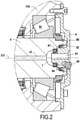
- the figure 1 and 2 present a system according to one aspect of the invention.
- the system as proposed comprises an axle secured to a vehicle chassis, a hydraulic device 3 mounted on the axle
- the hydraulic apparatus 3 comprises a shaft 4 forming here a wheel spindle.
- the hydraulic device 3 is here a hydraulic device with multilobe cam and radial pistons.
- the hydraulic apparatus 3 comprises a fixed part or stator, and a rotating part or rotor.
- the stator is coupled to the axle, while the rotor is coupled to shaft 4, so that shaft 4 is driven along an axis of rotation Z-Z.
- the shaft 4 is mounted to rotate along the first axis of rotation Z-Z via a bearing 5 comprising here two rolling elements 5A and 5B.
- the rolling elements 5A and 5B are two tapered bearings arranged in an O arrangement. Alternatively, the two bearings can be arranged in an X arrangement.
- the shaft 4 comprises a cylindrical part 41 extending along the axis of rotation ZZ, and a wheel support portion 42 extending from one end which is arbitrarily described as the proximal end 4P of the shaft 4.
- This support portion 42 is configured to allow the attachment of a wheel rim carrying a tire.
- the hydraulic device 3 is mounted around the shaft 4, so that a distal end 4D of the shaft 4 (opposite to the proximal end 4P along the axis of rotation ZZ) be accessible.
- the stator is coupled to the axle via a pivot, which defines a second axis of rotation, typically corresponding to a steering axis for a vehicle wheel.
- the assembly formed by the hydraulic device 3 and the wheel spindle 4 can thus pivot relative to the axle 1 along this second axis of rotation.
- the proposed structure can also be applied to a hydraulic device mounted fixed with respect to the axle. More generally, the proposed structure can be applied for a steering wheel or for a non-steering vehicle wheel, the structure then being able to be similar but lacking the pivot 2.
- the hydraulic device 3 as shown comprises a distributor 31, a cylinder block 32 defining a plurality of housings in which slide pistons 33 arranged radially with respect to the axis of rotation ZZ, a multi-lobe cam 34 disposed around the cylinder block 32 and a housing 35 defining an internal volume.
- the distributor 31 comprises a core 31a and a distribution casing 31b surrounding the core 31a.
- the picture 3 is thus a sectional view of the hydraulic device 3, highlighting the multi-lobe cam 34, the cylinder block 32 and the pistons 33.
- the pistons 33 typically comprise cylindrical rollers, which cooperate with the multi-lobe cam 34.
- the hydraulic device 3 is a machine with axial pistons, with vanes, with internal gears (commonly called a gerotor) or with external gears.
- the fixed part with respect to the axis of rotation ZZ or stator of the hydraulic device 3 is made up of the distributor 31, the multi-lobe cam 34 and the casing 35, while the rotating part or rotor consists of the shaft 4 and the cylinder block 32.
- the rolling elements 5A and 5B are arranged on either side of the hydraulic apparatus 3, so as to frame the cylinder block 32, the multi-lobe cam 34 and the distributor 31.
- the rolling element 5A is thus arranged to close to the proximal end 4P of the shaft 4, while the rolling element 5B is arranged close to the distal end 4D of the shaft4.
- the cylinder block 32, the multi-lobe cam 34 and the distributor 31 are thus arranged between the rolling elements 5A and 5B.
- the rolling elements 5A and 5B are both positioned between the cylinder block 32 and the proximal end 4P of the shaft 4.
- the hydraulic device 3 performs a driving function by being capable of driving a wheel mounted on the shaft 4 in rotation around the axis of rotation ZZ.
- Shaft 4 is driven by cylinder block 32 via splines.
- the shaft 4 further comprises a through channel 47, extending from the proximal end 4P to the distal end 4D.
- a flange 6 is positioned on the distal end 4D of the shaft 4, so as to isolate the rolling element 5B from the external environment, and to form an air chamber 7 in the extension of the through channel 47.
- the flange 6 comprises an intake duct 61 configured in such a way as to make it possible to connect a compressed air supply source (not shown in the figures) to the air chamber 7, and thus make it possible to achieve air circulation via the air chamber air 7 and through channel 47.
- the inlet duct 61 as shown passes through the flange 6 along the axis of rotation Z-Z. It is however understood that other variants are possible, in particular the fact of forming an inlet duct in the flange 6 which would be connected to a duct formed in the distribution casing 31b or in the casing of the hydraulic device 3. A As alternatives, the inlet duct 61 can be radially offset and/or inclined with respect to the axis of rotation ZZ.
- the air chamber 7 must be isolated from the internal volume of the hydraulic device 3 and the rolling elements (here the rolling element 5B) which are lubricated with oil or grease.
- Sealing elements are thus interposed between the flange 6 and the shaft 4 so as to isolate the air chamber 7 from the internal volume of the hydraulic apparatus 3 and from the rolling elements 5.
- two elements 81 and 82 are successively mounted between flange 6 and shaft 4. These two sealing elements 81 and 82 define an intermediate volume 84 between shaft 4 and flange 6.
- Sealing element 81 is an air seal, and is interposed between air chamber 7 and intermediate volume 84.
- Sealing element 82 is an oil seal, and is interposed between intermediate volume 84 and a volume of the hydraulic apparatus 3 comprising the rolling element 5B in the case where the latter is positioned close to the distal end 4D of the shaft 4 (as shown in the figure 1 ), or more generally a volume of the hydraulic apparatus 3 corresponding to the distributor 31, in particular in the case where the rolling elements 5A and 5B are positioned close to the proximal end 4P of the shaft 4.
- the element of sealing 81 and the sealing element 82 are thus typically of the lip ring type, such sealing elements being well known.
- the sealing elements 81 and 82 are typically interposed radially between the shaft 4 and the flange 6.
- the two sealing elements are arranged radially inside the shaft 4, which makes it possible to minimize the size of these sealing elements 81 and 82.
- the sealing element 82 can be mounted radially outside the shaft 4, or alternatively the two sealing elements 81 and 82 can be mounted radially outside the shaft 4.
- At least one sealing element among the sealing elements 81 and 82 can be fixed on the flange and rubbing on the shaft or conversely fixed on the shaft and rubbing on the flange.
- the flange 6 typically comprises a discharge valve 68 placed in a discharge orifice connecting the intermediate volume 84 to the ambient medium.
- the relief valve 68 is typically configured so as to allow an escape of fluid from the intermediate volume 84 to the ambient medium when the pressure within the intermediate volume 84 exceeds a predetermined threshold value.
- the relief valve 68 is typically configured to open for a pressure difference of less than 1 bar, or for example less than 0.5 bar.
- the discharge valve 68 thus typically makes it possible to discharge towards the ambient medium any excess pressure resulting from air leaks from the air chamber 7 towards the intermediate volume 84.
- the discharge valve 68 can open directly into the intermediate volume 84 or there be connected by a channel, or even be connected to the shaft 4, for example to a discharge duct arranged in the shaft 4.
- the association of the flange 6, the air chamber 7 and the through channel 47 thus makes it possible to form a compressed air supply line within the shaft 4 in order to carry out an adjustment of the pressure of a tire mounted on the shaft 4.
- the proposed system retains a simple structure, and the positioning of the flange 6 and the sealing elements 81 and 82 makes it possible to retain sealing elements 81 and 82 having standard and low diameters, unlike solutions which would consist in producing air supply ducts in the support portion 42 of the shaft 4 which then require the use of very large diameter sealing elements.
- the assembly of the proposed system is also facilitated due to the positioning of the elements such as the flange 6 and the sealing elements 81 and 82 at the level of a free end of the shaft 4.
- the flange 6 is typically fixed to the timing cover 31b via a plurality of fixing screws.
- the flange 6 is integral with the timing cover 31b.
- the proposed system thus makes it possible to adjust the inflation of the tires associated with the shaft 4, while guarding against the stresses resulting from the use of hoses at the wheel for the transmission of air which entail risks of rupture and for its cost
- the air chamber 7 can be formed directly in the shaft 4, or delimited by the shaft 4 and an additional element such as the flange 6, or even formed by a rotary joint tire positioned at the distal end of the shaft 4. More generally, it is understood that the air chamber 7 is formed at the distal end of the shaft 4 so as to be connected to the through channel 47 arranged in the shaft 4, but that several embodiments make it possible to delimit this air chamber 7 in order to obtain the technical effect indicated previously.
Landscapes
- Engineering & Computer Science (AREA)
- Mechanical Engineering (AREA)
- Chemical & Material Sciences (AREA)
- Combustion & Propulsion (AREA)
- Transportation (AREA)
- General Engineering & Computer Science (AREA)
- Actuator (AREA)
- Hydraulic Motors (AREA)
- Sealing Devices (AREA)
Claims (7)
- Hydraulische Vorrichtung (3), umfassend einen Stator und einen Rotor, wobei der Rotor gegenüber dem Stator entlang einer ersten Drehachse (Z-Z) drehbeweglich ist,eine Welle (4), die mit dem Rotor drehfest angebracht ist, wobei die Welle (4) eine Radhalterung (42) aufweist, die an einem proximalen Ende (4P) angeordnet ist und dazu ausgelegt ist, eine Felge und einen Reifen aufzunehmen,bei derdie Welle (4) einen Durchgangskanal (47) von dem proximalen Ende (4P) bis zu einem gegenüberliegenden distalen Ende (4D) aufweist,die hydraulische Vorrichtung (3) eine Luftkammer (7) umfasst, die an dem distalen Ende der Welle (4) ausgebildet und mit dem Durchgangskanal (47) verbunden ist, wobei der Durchgangskanal (47) und die Luftkammer (7) derart ausgebildet sind, dass eine Luftzirkulation ermöglicht wird, um den Druck eines Reifens zu kontrollieren,die Luftkammer vom Innenvolumen der hydraulischen Vorrichtung (3) durch wenigstens zwei Dichtungselemente (81, 82) isoliert ist, die zwischen sich ein Zwischenvolumen (84) definieren,wobei die hydraulische Vorrichtung (3) dadurch gekennzeichnet ist, dass die Luftkammer (7) wenigstens teilweise durch einen Flansch (6) begrenzt ist, der am distalen Ende der Welle (4) angebracht ist, und ein Entlastungsventil (68) umfasst, das das Zwischenvolumen (84) mit einem Umgebungsmedium verbindet, wobei das Entlastungsventil (86) so ausgelegt ist, dass ein Entweichen von Luft in Richtung des Umgebungsmediums erfolgt, wenn der Druck innerhalb des Zwischenvolumens (86) einen Schwellwert überschreitet.
- Hydraulische Vorrichtung (3) nach Anspruch 1, bei der der Flansch eine Einlassleitung (61) umfasst, die dazu ausgelegt ist, mit einer Druckquelle verbunden zu werden.
- Hydraulische Vorrichtung (3) nach einem der Ansprüche 1 oder 2, umfassend einen Fluidverteiler (31), einen Zylinderblock (32), der eine Vielzahl von Zylindern definiert, in denen Kolben (33) radial zu der ersten Drehachse (Z-Z) angeordnet sind, sowie einen mehrlappigen Nocken (34), der gegenüber dem Zylinderblock (32) angeordnet ist, wobei der Fluidverteiler (31), der Zylinderblock (32) und der mehrlappige Nocken (34) um die Welle (4) herum angeordnet sind.
- Hydraulische Vorrichtung (3) nach Anspruch 3, bei der der Verteiler (31) einen Kern (31a) und ein um den Kern (31a) herum angeordnetes Steuergehäuse (31b) umfasst, wobei eines von dem Steuergehäuse (31b), dem Nocken und dem Gehäuse (35) mit einem Lenkzapfen gekoppelt ist, so dass die hydraulische Vorrichtung (3) gegenüber der Radachse um eine zweite Drehachse schwenkbar angebracht ist.
- Hydraulische Vorrichtung (3) nach einem der Ansprüche 1 oder 2, eventuell in Kombination mit einem der Ansprüche 3 oder 4, bei der die Luftkammer (7) von dem Innenvolumen der hydraulischen Vorrichtung (3) durch zwei Dichtungselemente (81, 82) isoliert ist, die radial zwischen dem Flansch (6) und der Welle (4) angeordnet sind.
- Hydraulische Vorrichtung (3) nach Anspruch 5, bei der die beiden Dichtungselemente (81, 82) radial innerhalb der Welle (4) angebracht sind.
- Anordnung umfassend eine Radachse (1) eines Fahrzeugs und eine hydraulische Vorrichtung (3) nach einem der Ansprüche 1 bis 6, wobei der Stator der hydraulischen Vorrichtung (3) gegenüber der Radachse über ein Drehgelenk, das eine zweite Drehachse (XX) definiert, drehbar gelagert ist.
Applications Claiming Priority (2)
| Application Number | Priority Date | Filing Date | Title |
|---|---|---|---|
| FR1756164A FR3068300B1 (fr) | 2017-06-30 | 2017-06-30 | Appareil hydraulique ameliore comprenant une conduite pour la circulation d'air |
| PCT/FR2018/051597 WO2019002781A1 (fr) | 2017-06-30 | 2018-06-28 | Appareil hydraulique ameliore comprenant une conduite pour la circulation d'air |
Publications (2)
| Publication Number | Publication Date |
|---|---|
| EP3645320A1 EP3645320A1 (de) | 2020-05-06 |
| EP3645320B1 true EP3645320B1 (de) | 2022-01-19 |
Family
ID=60202108
Family Applications (1)
| Application Number | Title | Priority Date | Filing Date |
|---|---|---|---|
| EP18762349.1A Active EP3645320B1 (de) | 2017-06-30 | 2018-06-28 | Verbesserte hydraulische vorrichtung mit einer luftstromleitung |
Country Status (4)
| Country | Link |
|---|---|
| US (1) | US11498411B2 (de) |
| EP (1) | EP3645320B1 (de) |
| FR (1) | FR3068300B1 (de) |
| WO (1) | WO2019002781A1 (de) |
Families Citing this family (5)
| Publication number | Priority date | Publication date | Assignee | Title |
|---|---|---|---|---|
| FR3068299B1 (fr) * | 2017-06-30 | 2019-08-16 | Poclain Hydraulics Industrie | Pivot de direction ameliore formant un conduit pneumatique interne |
| IT202000024172A1 (it) * | 2020-10-14 | 2022-04-14 | Cnh Ind Italia Spa | Mozzo ruota di un veicolo agricolo o da lavoro |
| DE102021118902B4 (de) * | 2021-07-21 | 2025-09-18 | Illinois Tool Works Inc. | Drehübertragungsvorrichtung zum übertragen von steuer- und/oder arbeitsdrücken zu einem fluidkanal einer welle |
| CN115771355A (zh) * | 2022-11-18 | 2023-03-10 | 内蒙古第一机械集团股份有限公司 | 一种带有abs测速结构的中央充放气气道 |
| WO2026003214A1 (fr) | 2024-06-28 | 2026-01-02 | Poclain Hydraulics Industrie | Moteur hydraulique comprenant une conduite pour la circulation d'air |
Family Cites Families (23)
| Publication number | Priority date | Publication date | Assignee | Title |
|---|---|---|---|---|
| US5203391A (en) * | 1991-03-15 | 1993-04-20 | The Timken Company | Wheel mounting for tire pressure adjustment system |
| US5253688A (en) * | 1991-09-12 | 1993-10-19 | Tigges & Winckel Bonumwerke | Tire pressure control system |
| US6363985B1 (en) * | 2000-04-18 | 2002-04-02 | Spice Technology, Inc. | Rotary air coupling for tire inflation system |
| US6283186B1 (en) * | 1999-11-23 | 2001-09-04 | Dana Corporation | Tire inflation system for live spindle wheel end |
| US6325123B1 (en) * | 1999-12-23 | 2001-12-04 | Dana Corporation | Tire inflation system for a steering knuckle wheel end |
| US6668888B1 (en) * | 2002-07-19 | 2003-12-30 | Torque-Traction Technologies, Inc. | Central tire inflation system for steering drive axle |
| US7185688B2 (en) * | 2004-01-27 | 2007-03-06 | Arvinmeritor Technology, Llc | Central tire inflation system for drive axle |
| US7302979B2 (en) * | 2005-03-16 | 2007-12-04 | Dana Corporation | Vehicle tire inflation system and sensor and method of use |
| US20090084481A1 (en) * | 2007-10-01 | 2009-04-02 | Kalavitz Michael V | Tire inflation control method and apparatus |
| US7690412B1 (en) * | 2008-11-04 | 2010-04-06 | Arvinmeritor Technology, Llc | Drive axle with air passage for tire inflation system |
| US8915274B2 (en) * | 2009-01-22 | 2014-12-23 | Arvinmeritor Technology, Llc | Spindle for controlling wheel end endplay and preload |
| GB201118156D0 (en) * | 2011-10-21 | 2011-11-30 | Agco Int Gmbh | Rotatable shaft comprising fluid duct |
| US10059156B2 (en) * | 2012-04-09 | 2018-08-28 | Dana Heavy Vehicle Systems Group, Llc | Hub assembly for a tire inflation system |
| EP2653323B1 (de) * | 2012-04-19 | 2016-03-23 | DANA ITALIA S.p.A | Achsanordnung für Reifenfüllsystem |
| EP2969600B1 (de) * | 2013-03-15 | 2017-05-03 | Dana Heavy Vehicle Systems Group, LLC | Anordnung |
| US9333813B2 (en) * | 2013-08-13 | 2016-05-10 | Arvinmeritor Technology, Llc | Tire inflation system having a passage for routing pressurized gas through a flange |
| US10052923B2 (en) * | 2013-08-27 | 2018-08-21 | Arvinmeritor Technology, Llc | Tire inflation system with peristaltic pump |
| DE102013223512A1 (de) * | 2013-11-19 | 2015-05-21 | Robert Bosch Gmbh | Radantrieb mit Drehdurchführung |
| EP3164273B1 (de) * | 2014-07-02 | 2018-09-12 | DANA ITALIA S.p.A | Drehdichtung für eine zentrale reifenaufpumpanlage |
| US9511635B2 (en) * | 2014-07-10 | 2016-12-06 | Airgo Ip, Llc | Apparatus for delivering air through powered axle assemblies |
| FR3037533B1 (fr) * | 2015-06-16 | 2017-06-30 | Poclain Hydraulics Ind | Systeme pneumatique pour gonflage de roue integre a un essieu motorise |
| DE102015213692A1 (de) * | 2015-07-21 | 2017-01-26 | Robert Bosch Gmbh | Radnabenantrieb |
| US11034194B2 (en) * | 2015-10-20 | 2021-06-15 | Dana Heavy Vehicle Systems Group, Llc | Wheel end assembly for a tire inflation system and the tire inflation system made therewith |
-
2017
- 2017-06-30 FR FR1756164A patent/FR3068300B1/fr not_active Expired - Fee Related
-
2018
- 2018-06-28 EP EP18762349.1A patent/EP3645320B1/de active Active
- 2018-06-28 WO PCT/FR2018/051597 patent/WO2019002781A1/fr not_active Ceased
- 2018-06-28 US US16/627,245 patent/US11498411B2/en active Active
Non-Patent Citations (1)
| Title |
|---|
| "MOTEUR HYDRAULIQUE à PASSAGE CENTRAL D'AIR COMPRIMé", RESEARCH DISCLOSURE, KENNETH MASON PUBLICATIONS, HAMPSHIRE, UK, GB, no. 362, 1 June 1994 (1994-06-01), pages 289, XP000461259, ISSN: 0374-4353 * |
Also Published As
| Publication number | Publication date |
|---|---|
| FR3068300B1 (fr) | 2019-08-16 |
| WO2019002781A1 (fr) | 2019-01-03 |
| FR3068300A1 (fr) | 2019-01-04 |
| US11498411B2 (en) | 2022-11-15 |
| EP3645320A1 (de) | 2020-05-06 |
| US20200198415A1 (en) | 2020-06-25 |
Similar Documents
| Publication | Publication Date | Title |
|---|---|---|
| FR3068300B1 (fr) | Appareil hydraulique ameliore comprenant une conduite pour la circulation d'air | |
| BE1017719A3 (fr) | Systeme de gonflage de pneu pour fusee d'essieu et extremite de roue. | |
| EP3299656B1 (de) | Verbessertes bremssystem für hydraulische maschine | |
| WO2015185874A1 (fr) | Ensemble stator pour moteur-roue et son support-fusée | |
| EP3870833B1 (de) | Verbesserter hydraulischer motor für ein lenkbares rad eines fahrzeugs | |
| EP3106325B1 (de) | Pneumatisches system zum befüllen eines reifens, das in eine motorisierte achse integriert ist | |
| EP2795165B1 (de) | Ablauf für dynamische dichtungsanordnung | |
| EP3645328B1 (de) | Verbesserter lenkungsdrehzapfen, der einen internen pneumatischen durchgang bildet | |
| EP0480855B1 (de) | Übertragungseinrichtung für ein Fluid unter relativem Druck mit Hilfe einer Druckregeleinrichtung eines während der Fahrt aufblasbaren Reifens | |
| FR2967113A1 (fr) | Support de roue muni de conduits d'alimentation d'un appareil hydraulique | |
| FR2693154A1 (fr) | Ensemble d'un organe de déplacement moteur et du dispositif de son montage à pivotement. | |
| FR3003315A1 (fr) | Pompe a engrenage a denture interieure | |
| EP3329154B1 (de) | Druckbegrenzungsvorrichtung, insbesondere für ein assistenzsystem für fahrzeuge | |
| JP2008239025A (ja) | 車輪用転がり軸受装置 | |
| FR2694342A1 (fr) | Moteur à fluide sous pression comportant un ralentisseur interne et groupe d'entraînement en faisant application et comportant un organe d'immobilisation. | |
| FR3123403A1 (fr) | Ensemble d’étanchéité, système de télégonflage et véhicule automobile associés | |
| EP3406901B1 (de) | Hydraulisches gerät, das einen verbesserten verteiler umfasst | |
| FR3106635A1 (fr) | Assemblage de ROue de véhicule automobile | |
| EP0487394B1 (de) | Drückflüssigkeitsvorrichtung mit einer besonderen Anordnung der Flüssigkeitszufuhrkanäle für den Zylinder | |
| FR3154770A1 (fr) | Machine hydrostatique de rotation à pistons radiaux et à distribution optimisée | |
| WO2026003214A1 (fr) | Moteur hydraulique comprenant une conduite pour la circulation d'air | |
| FR2724437A1 (fr) | Groupe d'entrainement hydromecanique | |
| FR2992374A1 (fr) | Pompe a engrenage a denture interieure | |
| FR3039621A1 (fr) | Limiteur de pression comprenant deux clapets de selecteur separes | |
| FR2842146A1 (fr) | Entrainement de moyeux de roue comportant un support de moyeu directionnel |
Legal Events
| Date | Code | Title | Description |
|---|---|---|---|
| STAA | Information on the status of an ep patent application or granted ep patent |
Free format text: STATUS: UNKNOWN |
|
| STAA | Information on the status of an ep patent application or granted ep patent |
Free format text: STATUS: THE INTERNATIONAL PUBLICATION HAS BEEN MADE |
|
| PUAI | Public reference made under article 153(3) epc to a published international application that has entered the european phase |
Free format text: ORIGINAL CODE: 0009012 |
|
| STAA | Information on the status of an ep patent application or granted ep patent |
Free format text: STATUS: REQUEST FOR EXAMINATION WAS MADE |
|
| 17P | Request for examination filed |
Effective date: 20200127 |
|
| AK | Designated contracting states |
Kind code of ref document: A1 Designated state(s): AL AT BE BG CH CY CZ DE DK EE ES FI FR GB GR HR HU IE IS IT LI LT LU LV MC MK MT NL NO PL PT RO RS SE SI SK SM TR |
|
| AX | Request for extension of the european patent |
Extension state: BA ME |
|
| DAV | Request for validation of the european patent (deleted) | ||
| DAX | Request for extension of the european patent (deleted) | ||
| STAA | Information on the status of an ep patent application or granted ep patent |
Free format text: STATUS: EXAMINATION IS IN PROGRESS |
|
| 17Q | First examination report despatched |
Effective date: 20201126 |
|
| RIC1 | Information provided on ipc code assigned before grant |
Ipc: F04B 1/043 20200101ALI20210804BHEP Ipc: B60K 7/00 20060101ALI20210804BHEP Ipc: B60C 23/00 20060101AFI20210804BHEP |
|
| GRAP | Despatch of communication of intention to grant a patent |
Free format text: ORIGINAL CODE: EPIDOSNIGR1 |
|
| STAA | Information on the status of an ep patent application or granted ep patent |
Free format text: STATUS: GRANT OF PATENT IS INTENDED |
|
| INTG | Intention to grant announced |
Effective date: 20210923 |
|
| GRAS | Grant fee paid |
Free format text: ORIGINAL CODE: EPIDOSNIGR3 |
|
| GRAA | (expected) grant |
Free format text: ORIGINAL CODE: 0009210 |
|
| STAA | Information on the status of an ep patent application or granted ep patent |
Free format text: STATUS: THE PATENT HAS BEEN GRANTED |
|
| AK | Designated contracting states |
Kind code of ref document: B1 Designated state(s): AL AT BE BG CH CY CZ DE DK EE ES FI FR GB GR HR HU IE IS IT LI LT LU LV MC MK MT NL NO PL PT RO RS SE SI SK SM TR |
|
| REG | Reference to a national code |
Ref country code: GB Ref legal event code: FG4D Free format text: NOT ENGLISH |
|
| REG | Reference to a national code |
Ref country code: CH Ref legal event code: EP |
|
| REG | Reference to a national code |
Ref country code: DE Ref legal event code: R096 Ref document number: 602018029803 Country of ref document: DE |
|
| REG | Reference to a national code |
Ref country code: AT Ref legal event code: REF Ref document number: 1463596 Country of ref document: AT Kind code of ref document: T Effective date: 20220215 |
|
| REG | Reference to a national code |
Ref country code: IE Ref legal event code: FG4D Free format text: LANGUAGE OF EP DOCUMENT: FRENCH |
|
| REG | Reference to a national code |
Ref country code: LT Ref legal event code: MG9D |
|
| REG | Reference to a national code |
Ref country code: NL Ref legal event code: MP Effective date: 20220119 |
|
| REG | Reference to a national code |
Ref country code: AT Ref legal event code: MK05 Ref document number: 1463596 Country of ref document: AT Kind code of ref document: T Effective date: 20220119 |
|
| PG25 | Lapsed in a contracting state [announced via postgrant information from national office to epo] |
Ref country code: NL Free format text: LAPSE BECAUSE OF FAILURE TO SUBMIT A TRANSLATION OF THE DESCRIPTION OR TO PAY THE FEE WITHIN THE PRESCRIBED TIME-LIMIT Effective date: 20220119 |
|
| PG25 | Lapsed in a contracting state [announced via postgrant information from national office to epo] |
Ref country code: SE Free format text: LAPSE BECAUSE OF FAILURE TO SUBMIT A TRANSLATION OF THE DESCRIPTION OR TO PAY THE FEE WITHIN THE PRESCRIBED TIME-LIMIT Effective date: 20220119 Ref country code: RS Free format text: LAPSE BECAUSE OF FAILURE TO SUBMIT A TRANSLATION OF THE DESCRIPTION OR TO PAY THE FEE WITHIN THE PRESCRIBED TIME-LIMIT Effective date: 20220119 Ref country code: PT Free format text: LAPSE BECAUSE OF FAILURE TO SUBMIT A TRANSLATION OF THE DESCRIPTION OR TO PAY THE FEE WITHIN THE PRESCRIBED TIME-LIMIT Effective date: 20220519 Ref country code: NO Free format text: LAPSE BECAUSE OF FAILURE TO SUBMIT A TRANSLATION OF THE DESCRIPTION OR TO PAY THE FEE WITHIN THE PRESCRIBED TIME-LIMIT Effective date: 20220419 Ref country code: LT Free format text: LAPSE BECAUSE OF FAILURE TO SUBMIT A TRANSLATION OF THE DESCRIPTION OR TO PAY THE FEE WITHIN THE PRESCRIBED TIME-LIMIT Effective date: 20220119 Ref country code: HR Free format text: LAPSE BECAUSE OF FAILURE TO SUBMIT A TRANSLATION OF THE DESCRIPTION OR TO PAY THE FEE WITHIN THE PRESCRIBED TIME-LIMIT Effective date: 20220119 Ref country code: ES Free format text: LAPSE BECAUSE OF FAILURE TO SUBMIT A TRANSLATION OF THE DESCRIPTION OR TO PAY THE FEE WITHIN THE PRESCRIBED TIME-LIMIT Effective date: 20220119 Ref country code: BG Free format text: LAPSE BECAUSE OF FAILURE TO SUBMIT A TRANSLATION OF THE DESCRIPTION OR TO PAY THE FEE WITHIN THE PRESCRIBED TIME-LIMIT Effective date: 20220419 |
|
| PG25 | Lapsed in a contracting state [announced via postgrant information from national office to epo] |
Ref country code: PL Free format text: LAPSE BECAUSE OF FAILURE TO SUBMIT A TRANSLATION OF THE DESCRIPTION OR TO PAY THE FEE WITHIN THE PRESCRIBED TIME-LIMIT Effective date: 20220119 Ref country code: LV Free format text: LAPSE BECAUSE OF FAILURE TO SUBMIT A TRANSLATION OF THE DESCRIPTION OR TO PAY THE FEE WITHIN THE PRESCRIBED TIME-LIMIT Effective date: 20220119 Ref country code: GR Free format text: LAPSE BECAUSE OF FAILURE TO SUBMIT A TRANSLATION OF THE DESCRIPTION OR TO PAY THE FEE WITHIN THE PRESCRIBED TIME-LIMIT Effective date: 20220420 Ref country code: FI Free format text: LAPSE BECAUSE OF FAILURE TO SUBMIT A TRANSLATION OF THE DESCRIPTION OR TO PAY THE FEE WITHIN THE PRESCRIBED TIME-LIMIT Effective date: 20220119 Ref country code: AT Free format text: LAPSE BECAUSE OF FAILURE TO SUBMIT A TRANSLATION OF THE DESCRIPTION OR TO PAY THE FEE WITHIN THE PRESCRIBED TIME-LIMIT Effective date: 20220119 |
|
| PG25 | Lapsed in a contracting state [announced via postgrant information from national office to epo] |
Ref country code: IS Free format text: LAPSE BECAUSE OF FAILURE TO SUBMIT A TRANSLATION OF THE DESCRIPTION OR TO PAY THE FEE WITHIN THE PRESCRIBED TIME-LIMIT Effective date: 20220519 |
|
| REG | Reference to a national code |
Ref country code: DE Ref legal event code: R097 Ref document number: 602018029803 Country of ref document: DE |
|
| PG25 | Lapsed in a contracting state [announced via postgrant information from national office to epo] |
Ref country code: SM Free format text: LAPSE BECAUSE OF FAILURE TO SUBMIT A TRANSLATION OF THE DESCRIPTION OR TO PAY THE FEE WITHIN THE PRESCRIBED TIME-LIMIT Effective date: 20220119 Ref country code: SK Free format text: LAPSE BECAUSE OF FAILURE TO SUBMIT A TRANSLATION OF THE DESCRIPTION OR TO PAY THE FEE WITHIN THE PRESCRIBED TIME-LIMIT Effective date: 20220119 Ref country code: RO Free format text: LAPSE BECAUSE OF FAILURE TO SUBMIT A TRANSLATION OF THE DESCRIPTION OR TO PAY THE FEE WITHIN THE PRESCRIBED TIME-LIMIT Effective date: 20220119 Ref country code: EE Free format text: LAPSE BECAUSE OF FAILURE TO SUBMIT A TRANSLATION OF THE DESCRIPTION OR TO PAY THE FEE WITHIN THE PRESCRIBED TIME-LIMIT Effective date: 20220119 Ref country code: DK Free format text: LAPSE BECAUSE OF FAILURE TO SUBMIT A TRANSLATION OF THE DESCRIPTION OR TO PAY THE FEE WITHIN THE PRESCRIBED TIME-LIMIT Effective date: 20220119 Ref country code: CZ Free format text: LAPSE BECAUSE OF FAILURE TO SUBMIT A TRANSLATION OF THE DESCRIPTION OR TO PAY THE FEE WITHIN THE PRESCRIBED TIME-LIMIT Effective date: 20220119 |
|
| PLBE | No opposition filed within time limit |
Free format text: ORIGINAL CODE: 0009261 |
|
| STAA | Information on the status of an ep patent application or granted ep patent |
Free format text: STATUS: NO OPPOSITION FILED WITHIN TIME LIMIT |
|
| PG25 | Lapsed in a contracting state [announced via postgrant information from national office to epo] |
Ref country code: AL Free format text: LAPSE BECAUSE OF FAILURE TO SUBMIT A TRANSLATION OF THE DESCRIPTION OR TO PAY THE FEE WITHIN THE PRESCRIBED TIME-LIMIT Effective date: 20220119 |
|
| 26N | No opposition filed |
Effective date: 20221020 |
|
| PG25 | Lapsed in a contracting state [announced via postgrant information from national office to epo] |
Ref country code: MC Free format text: LAPSE BECAUSE OF FAILURE TO SUBMIT A TRANSLATION OF THE DESCRIPTION OR TO PAY THE FEE WITHIN THE PRESCRIBED TIME-LIMIT Effective date: 20220119 |
|
| REG | Reference to a national code |
Ref country code: CH Ref legal event code: PL |
|
| REG | Reference to a national code |
Ref country code: BE Ref legal event code: MM Effective date: 20220630 |
|
| PG25 | Lapsed in a contracting state [announced via postgrant information from national office to epo] |
Ref country code: SI Free format text: LAPSE BECAUSE OF FAILURE TO SUBMIT A TRANSLATION OF THE DESCRIPTION OR TO PAY THE FEE WITHIN THE PRESCRIBED TIME-LIMIT Effective date: 20220119 |
|
| GBPC | Gb: european patent ceased through non-payment of renewal fee |
Effective date: 20220628 |
|
| PG25 | Lapsed in a contracting state [announced via postgrant information from national office to epo] |
Ref country code: LU Free format text: LAPSE BECAUSE OF NON-PAYMENT OF DUE FEES Effective date: 20220628 Ref country code: LI Free format text: LAPSE BECAUSE OF NON-PAYMENT OF DUE FEES Effective date: 20220630 Ref country code: IE Free format text: LAPSE BECAUSE OF NON-PAYMENT OF DUE FEES Effective date: 20220628 Ref country code: CH Free format text: LAPSE BECAUSE OF NON-PAYMENT OF DUE FEES Effective date: 20220630 |
|
| PG25 | Lapsed in a contracting state [announced via postgrant information from national office to epo] |
Ref country code: GB Free format text: LAPSE BECAUSE OF NON-PAYMENT OF DUE FEES Effective date: 20220628 Ref country code: BE Free format text: LAPSE BECAUSE OF NON-PAYMENT OF DUE FEES Effective date: 20220630 |
|
| P01 | Opt-out of the competence of the unified patent court (upc) registered |
Effective date: 20230513 |
|
| PG25 | Lapsed in a contracting state [announced via postgrant information from national office to epo] |
Ref country code: IT Free format text: LAPSE BECAUSE OF FAILURE TO SUBMIT A TRANSLATION OF THE DESCRIPTION OR TO PAY THE FEE WITHIN THE PRESCRIBED TIME-LIMIT Effective date: 20220119 |
|
| PG25 | Lapsed in a contracting state [announced via postgrant information from national office to epo] |
Ref country code: MK Free format text: LAPSE BECAUSE OF FAILURE TO SUBMIT A TRANSLATION OF THE DESCRIPTION OR TO PAY THE FEE WITHIN THE PRESCRIBED TIME-LIMIT Effective date: 20220119 Ref country code: CY Free format text: LAPSE BECAUSE OF FAILURE TO SUBMIT A TRANSLATION OF THE DESCRIPTION OR TO PAY THE FEE WITHIN THE PRESCRIBED TIME-LIMIT Effective date: 20220119 |
|
| PG25 | Lapsed in a contracting state [announced via postgrant information from national office to epo] |
Ref country code: HU Free format text: LAPSE BECAUSE OF FAILURE TO SUBMIT A TRANSLATION OF THE DESCRIPTION OR TO PAY THE FEE WITHIN THE PRESCRIBED TIME-LIMIT; INVALID AB INITIO Effective date: 20180628 |
|
| PG25 | Lapsed in a contracting state [announced via postgrant information from national office to epo] |
Ref country code: MT Free format text: LAPSE BECAUSE OF FAILURE TO SUBMIT A TRANSLATION OF THE DESCRIPTION OR TO PAY THE FEE WITHIN THE PRESCRIBED TIME-LIMIT Effective date: 20220119 |
|
| PGFP | Annual fee paid to national office [announced via postgrant information from national office to epo] |
Ref country code: DE Payment date: 20250617 Year of fee payment: 8 |
|
| PGFP | Annual fee paid to national office [announced via postgrant information from national office to epo] |
Ref country code: FR Payment date: 20250617 Year of fee payment: 8 |
|
| PG25 | Lapsed in a contracting state [announced via postgrant information from national office to epo] |
Ref country code: TR Free format text: LAPSE BECAUSE OF FAILURE TO SUBMIT A TRANSLATION OF THE DESCRIPTION OR TO PAY THE FEE WITHIN THE PRESCRIBED TIME-LIMIT Effective date: 20220119 |