EP3872015A1 - Verfahren und roboter zur bestimmung einer höhe einer aufzugsstufe in einer aufzugsanordnung - Google Patents
Verfahren und roboter zur bestimmung einer höhe einer aufzugsstufe in einer aufzugsanordnung Download PDFInfo
- Publication number
- EP3872015A1 EP3872015A1 EP20159906.5A EP20159906A EP3872015A1 EP 3872015 A1 EP3872015 A1 EP 3872015A1 EP 20159906 A EP20159906 A EP 20159906A EP 3872015 A1 EP3872015 A1 EP 3872015A1
- Authority
- EP
- European Patent Office
- Prior art keywords
- robot
- drive wheels
- sill
- elevator
- support structure
- Prior art date
- Legal status (The legal status is an assumption and is not a legal conclusion. Google has not performed a legal analysis and makes no representation as to the accuracy of the status listed.)
- Withdrawn
Links
- 238000000034 method Methods 0.000 title claims abstract description 31
- 239000003381 stabilizer Substances 0.000 claims description 16
- 230000001133 acceleration Effects 0.000 claims description 14
- 230000007704 transition Effects 0.000 claims description 13
- 230000033001 locomotion Effects 0.000 description 10
- 238000006073 displacement reaction Methods 0.000 description 6
- 230000000284 resting effect Effects 0.000 description 5
- 238000013459 approach Methods 0.000 description 4
- 230000005484 gravity Effects 0.000 description 4
- 230000001276 controlling effect Effects 0.000 description 3
- 230000000875 corresponding effect Effects 0.000 description 3
- 238000004140 cleaning Methods 0.000 description 2
- 238000012423 maintenance Methods 0.000 description 2
- 238000006243 chemical reaction Methods 0.000 description 1
- 230000002596 correlated effect Effects 0.000 description 1
- 230000001419 dependent effect Effects 0.000 description 1
- 238000007689 inspection Methods 0.000 description 1
- 238000009434 installation Methods 0.000 description 1
- 239000004065 semiconductor Substances 0.000 description 1
- 230000006641 stabilisation Effects 0.000 description 1
Images

Classifications
-
- B—PERFORMING OPERATIONS; TRANSPORTING
- B66—HOISTING; LIFTING; HAULING
- B66B—ELEVATORS; ESCALATORS OR MOVING WALKWAYS
- B66B1/00—Control systems of elevators in general
- B66B1/34—Details, e.g. call counting devices, data transmission from car to control system, devices giving information to the control system
- B66B1/36—Means for stopping the cars, cages, or skips at predetermined levels
- B66B1/40—Means for stopping the cars, cages, or skips at predetermined levels and for correct levelling at landings
-
- B—PERFORMING OPERATIONS; TRANSPORTING
- B66—HOISTING; LIFTING; HAULING
- B66B—ELEVATORS; ESCALATORS OR MOVING WALKWAYS
- B66B19/00—Mining-hoist operation
-
- B—PERFORMING OPERATIONS; TRANSPORTING
- B66—HOISTING; LIFTING; HAULING
- B66B—ELEVATORS; ESCALATORS OR MOVING WALKWAYS
- B66B5/00—Applications of checking, fault-correcting, or safety devices in elevators
- B66B5/0087—Devices facilitating maintenance, repair or inspection tasks
Definitions
- the present invention relates to a method and to a robot for determining a height of an elevator step in an elevator arrangement.
- An elevator arrangement typically comprises an elevator car which may be displaced vertically throughout a building. Therein, the elevator car may be displaced relative to multiple landings at various levels within the building. Each landing may be located at one of multiple floors within the building. The elevator car may be stopped at one of the landings such that passengers may enter or exit from the elevator car. Upon such stop, a car sill, i.e. a floor of the elevator car, adjoins a landing sill, i.e. a floor of the landing. In order to enable frictionless displacing of the elevator car within an elevator shaft connecting the various landings, a lateral gap extends between the car sill and the landing sill. Such gap typically has a width of between a few millimetres and a few centimetres.
- a substantial elevator step i.e. generation of a substantial difference in height level between the car sill and the landing sill
- generation of a substantial elevator step should be avoided as such elevator step may for example generate an obstacle for passengers upon entering or exiting the elevator car.
- the car sill and the landing sill should be substantially flush upon the elevator car being stopped at one of the landings, with a remaining elevator step being preferably smaller than a predefined height limit of for example a few millimetres (e.g. ⁇ 5 mm or even ⁇ 2 mm).
- Such calibration is performed by a technician.
- the technician may for example travel with the elevator cabin and stop at each of the landings in order to then check whether or not excessive elevator steps are generated. If necessary, the technician may then for example reconfigure a controller of the elevator arrangement such as to suitably adapt stopping positions of the elevator car in order to avoid such excessive elevator steps.
- calibrating an operation of the elevator arrangement by a technician may require significant human efforts, thereby possibly significantly adding to installation and/or maintenance costs. Furthermore, such calibration procedure by a technician may be prone to human-related errors.
- WO 2018/198224 A1 discloses a height difference inspection device for elevators.
- the elevator arrangement comprises an elevator car being vertically displaceable relative to multiple landings at various levels within a building.
- a car sill adjoins a landing sill at a transition area with a gap extending between the car sill and the landing sill, the elevator step being generated between the car sill and the landing sill upon the car sill not being flush with the landing sill.
- the method being implemented using a robot.
- the robot comprises a support structure, at least two drive wheels, a mobilisation unit, a controller and a cliff sensor.
- the at least two drive wheels are fixed to the support structure in a rotatable manner at a vertically fixed location relative to the support structure.
- the mobilisation unit is configured for driving each of the at least two drive wheels to thereby displace the robot along a ground surface.
- the controller is configured for controlling displacing the robot within accessible areas within the building by instructing the mobilisation unit.
- the cliff sensor is configured for detecting a cliff at the ground surface underneath the cliff sensor, the cliff sensor being arranged at a predetermined position with respect to the at least two drive wheels of the robot.
- the method comprises at least the following steps, preferably in the indicated order:
- a robot for determining a height of an elevator step in an elevator arrangement is proposed.
- the elevator arrangement is configured in a same manner as described above for the first aspect of the invention and the robot comprises the components as defined above for the first aspect of the invention.
- the robot is configured for one of executing and controlling the method according to an embodiment of the first aspect of the invention.
- a robot may be used for approaching the transition area between a landing and an elevator car being stopped at this landing and for determining the height of the elevator step established between the landing sill and the car sill.
- the robot has to be mobile such that it may be controllably displaced throughout an accessible area within a building and its elevator arrangement.
- the robot may be provided with wheels such that the robot may roll along a ground surface at floors of the building as well as at a floor of the elevator car.
- the robot may have a support structure which for example supports or holds other components of the robot.
- Such support structure may for example be a casing or a chassis to which the other components of the robot are fixed.
- the robot may then comprise at least two drive wheels.
- Each of such drive wheels may be fixed to the support structure in a rotatable manner.
- a rotation axis of such drive wheel may be substantially horizontal.
- the rotation axis of this drive wheel may be located at a vertically fixed location relative to the support structure.
- the drive wheel may rotate around its rotation axis, its position relative to the support structure should be fixed at least in a vertical direction. Accordingly, when one of the drive wheels is set to another height level, also a level of the support structure of the robot is modified at least at the side where the drive wheel is fixed to the support structure. Having two such drive wheels, the robot may be displaced along a ground surface in a precisely defined manner.
- the robot may have more than two drive wheels
- the robot preferably comprises exactly two drive wheels.
- a vertical position of the support structure of the robot at least in a plane including a virtual connection line between these two drive wheels may be precisely defined.
- no situation may occur generally where one of the drive wheels is not in contact with the ground surface while the robot is being displaced along the ground surface. Accordingly, a current height level and/or tilt angle of the support structure always unambiguously correlate with locations of the drive wheels.
- the drive wheels may be arranged at, close to or outside of a circumference of the robot's support structure.
- the drive wheels may be arranged at opposite sides of the support structure.
- the robot may comprise at least one stabiliser wheel.
- Such stabiliser wheel may also be fixed to the support structure in a rotatable manner.
- the stabiliser wheel should be fixed to the support structure at a vertically displaceable location relative to the support structure.
- a level of the stabiliser wheel with regard to the robot's support structure may change within an allowable height range.
- Such allowable height range may be between some millimetres and a few centimetres, e.g. between 2 mm and 5 cm.
- the stabiliser wheel when such stabiliser wheel is set to another height level, this does not necessarily influence the height level and/or tilt angle of the support structure of the robot, at least as long as the stabiliser wheel remains within its allowable height range. Accordingly, on the one hand, the stabiliser wheel may prevent the robot with its support structure from excessively inclining, tilting or even falling over. However, on the other hand, the stabiliser wheel may adapt its height position for example to an unevenness or small bumps on the floor forming the ground surface.
- the one or more stabiliser wheels may be arranged at, close to or outside of a circumference of the robot's support structure. Particularly, for example two stabiliser wheels may be arranged at opposite sides of the support structure.
- the support structure of the robot may be moved and guided along the ground surface while being hindered from excessively tilting or falling over and, at the same time, allowing to absorb or roll over small height irregularities occurring at such ground surface.
- the mobilisation unit is configured for driving each of the drive wheels.
- the mobilisation unit may comprise at least one motor, for example an electric motor, for rotatably driving the drive wheels.
- the mobilisation unit comprises two or more motors, one motor being associated to each one of the drive wheels for driving it independently from the other drive wheels.
- the mobilisation unit may comprise a gear unit for transmitting drive motions of the one or more motors to associated one or more of the drive wheels.
- the mobilisation unit may be configured for driving each of the drive wheels independent from other drive wheels.
- one drive wheel may be driven in an opposite direction and/or with a difference speed compared to other drive wheels. Accordingly, by suitably driving the at least two drive wheels, the robot may be displaced and/or reoriented, i.e. rotated around a vertical axis, in a desired manner.
- the controller is configured for controlling motions of the robot by sending instructions to the mobilisation unit.
- the controller may have information about a current location of the robot and/or about an intended target location. Using such information, the controller may determine a suitable displacement path for arriving at the target location and may transmit instructions to the mobilisation unit for displacing the robot along this displacement path.
- the robot may further comprise a navigation unit for providing navigation data.
- the navigation data may include information about a current position of the robot within the building and information about the accessible areas within the building. The displacing of the robot to the first position may then be controlled based on the navigation data.
- the navigation unit may supply navigation data to other components of the robot, particularly to the controller.
- such navigation data may provide information about the current location of the robot.
- Such information may be provided based on data or signals received from a global positioning system or a local positioning system within the building.
- the navigation unit may provide information about the accessible areas within the building.
- the navigation unit may comprise a map of areas and paths being accessible within the building. Using such map and knowing the robot's current position, the navigation unit and/or the controller may determine the suitable displacement path for driving the robot to the target location.
- the robot Upon being driven throughout the accessible areas within a building, there may be a risk that the robot approaches areas in which for example steps of stairs limit a further motion of the robot. Particularly, the robot should be prevented from crossing an edge of such step and then possibly falling down the stairs. Similarly, the robot should be prevented from crossing edges of a landing and then falling into an abyss in a stairway. An edge of the step or of the landing may also be referred to as a cliff.
- the robot For detecting the edge of a step or the edge of a landing, the robot generally comprises a so-called cliff sensor.
- the cliff sensor is configured for detecting structures in a neighbourhood of the robot which may be interpreted as representing the edge of a step or the edge of a landing. Upon detecting such structures, the cliff sensor may provide a signal to the controller for warning the controller due to the presence of the edge to the step or abyss. The controller may then e.g. stop a further forward motion of the robot to prevent the robot from crossing this edge.
- the cliff sensor may be configured for detecting the cliff based on measuring a distance between the cliff sensor and a target located vertically underneath the cliff sensor.
- the cliff sensor may be implemented using a distance measuring device.
- Such distance measuring device may measure a distance with respect to a target.
- the distance measuring device may be implemented and arranged such that it may measure a distance to a target which is located underneath, i.e. at a lower vertical level than, the cliff sensor.
- the target may be a ground surface on which the robot is displaced, i.e. on which the drive wheels of the robot may roll.
- the cliff sensor detects that its vertical distance from such ground surface suddenly increases by more than an acceptable predetermined limit, this may be interpreted as indicating the presence of a cliff.
- the robot may stop, deviate or reverse its motion.
- the cliff sensor may comprise a light emitter and a light detector.
- the cliff sensor may then be configured for detecting the cliff based on measuring a distance between the cliff sensor and a target located vertically underneath the cliff sensor by emitting a light pulse by the light emitter and detecting the light pulse upon being reflected at the target.
- the cliff sensor may be implemented with a light source which may emit a directed light pulse in a direction towards for example the ground surface underneath the robot.
- the light source or light emitter may be a laser.
- the light pulse When the light pulse reaches an obstacle such as the ground surface, it is at least partially reflected back towards the cliff sensor.
- the light detector of the cliff sensor may then detect such reflected light pulse portion.
- the distance between the cliff sensor and the ground surface may be determined.
- TOF time-of-flight
- the cliff sensor may suddenly no more detect any reflected light pulses. Accordingly, based on the signals output by the cliff sensor, the cliff may be reliably detected.
- the robot may then be used for determining the height of an elevator step by executing a suitable method in accordance with embodiments of the present invention.
- the robot may originally be located somewhere at a landing or somewhere within the elevator car.
- the robot may know its own position e.g. from navigation data provided for example by the navigation unit. Furthermore, the robot may know where the transition area between the landing and the elevator car is located.
- the robot may first be displaced towards of the transition area.
- the robot may then be further displaced such that at least a portion of the robot crosses the gap extending between the car sill and the landing sill.
- Such portion of the robot may comprise the cliff sensor.
- the cliff sensor may be included in the portion of the robot which is first reaching the gap. This is particularly true in case the cliff sensor is arranged at the circumference of the robot, particularly in displacement direction of the robot. In such case, the cliff sensor immediately detects the gap as soon as the circumference of the robot reaches the gap.
- the robot may first cross the gap with a portion close to such circumference until, sooner or later, the cliff sensor being arranged remote from this circumference will reach a position at which it detects the gap.
- the position at which the robot is when its cliff sensor detects the gap for the first time is referred to herein as the first position.
- the at least two drive wheels of the robot are generally both arranged at one side of the gap extending between the landing sill and the car sill.
- the first position will generally be set such that both drive wheels of the robot still rest on the landing sill side of the gap.
- the first position will generally be set such that both drive wheels of the robot still rest within the elevator car on the car sill side of the gap.
- the cliff sensor may generally detect the gap between the landing sill and the car sill, as such gap typically has a very similar structure as e.g. an edge of a stair step or an edge of a landing abutting to an abyss. Particularly, at such gap, a ground surface suddenly "disappears" for the cliff sensor, i.e. the cliff sensor sends its light pulses into this gap and therefore does no more detect reflected light pulse portions or suddenly measures a strongly increased distance with regards to a reflecting target surface.
- the robot will stop or reverse its motion in order to avoid falling over the cliff.
- the robot may be further displaced towards a second position. Such second position may be such that the robot continues to cross the gap.
- Whether or not a detected cliff corresponds to an edge of a stair step or landing, a crossing of which is to be avoided by the robot, or whether the detected cliff corresponds to the gap between the landing sill and the car sill may be determined by the robot preferably automatically.
- the robot may distinguish between both cases based on information included in the navigation data.
- the robot may have further sensors such as a lidar sensor and/or ultrasonic sensors which allow distinguishing both cases.
- the second position should be set such that one of the at least two drive wheels of the robot is standing on the landing sill whereas another one of the drive wheels is standing on the car sill.
- the robot shall be displaced to the second position such that it rests with one of its drive wheels on the landing sill while resting with another one of its drive wheels on the car sill.
- the robot In order to determine how the robot may be displaced from the first position to such specific second position, it may have to be taken into account where the cliff sensor is arranged at the support structure of the robot with respect to the location where the at least two drive wheels of the robot are arranged at the support structure.
- the known relative positioning of the cliff sensor, on the one hand, and the drive wheels, on the other hand may be taken into account.
- the robot will have to cross the elevator step between both sills with at least one of its drive wheels while at least another one of the drive wheels does not cross this elevator step.
- the entire robot including its support structure will no more be arranged horizontally, i.e. parallel to the horizontal ground surface. Instead, the entire robot will be inclined by a tilt angle.
- the tilt angle of the support structure is precisely defined as it is depending on the different levels of the landing sill and the car sill, as the drive wheels are arranged at the support structure at vertically fixed locations relative to the support structure.
- the tilt angle of the support structure may therefore be measured for deriving information therefrom about the different levels of the landing sill and the car sill.
- the robot may comprise an acceleration sensor.
- the robot may then be configured for measuring the tilt angle of its support structure based on signals from the acceleration sensor.
- the acceleration sensor may for example be configured for sensing accelerations acting onto the robot in one or more spatial directions.
- the acceleration sensor may be configured for sensing accelerations acting in each of three spatial directions being orthogonal to each other.
- gravity is an acceleration generally acting onto the robot
- the acceleration sensor may be used for detecting a tilt angle with which the support structure of the robot is inclined with respect to a vertical direction indicated by the gravity direction.
- the acceleration sensor may be for example a small semiconductor device.
- signals from the acceleration sensor may be correlated with information comprised in navigation data in order to determine for example a current orientation of the robot within a map represented in the navigation data.
- this information may finally be used for determining the height of the elevator step.
- the pre-known information about the relative position of the two drive wheels with respect to the gap upon the robot being arranged in the second position may be taken into account.
- this information is acquired not only taking into account the tilt angle of the support structure but additionally also taking into account where the drive wheels of the robot are located relative to the gap between the landing sill and the car sill.
- the mobilisation unit may be controlled to turn the robot around a vertical rotation axis for displacing the robot from the first position to the second position.
- the robot may be displaced from the first position to the second position not, or at least not only or not mainly, by displacing the robot linearly, i.e. displacing a centre of gravity of the robot.
- displacement from the first to the second position may be implemented by reorienting, i.e. turning the robot around its vertical axis. For such turning of the robot, for example only one of the at least two drive wheels is driven or both drive wheels are driven but at different speeds and/or in opposite directions.
- Such reorienting of the robot may present a particularly reliable manner of arranging the robot at the second position with one of its drive wheels resting on the car sill and one of its drive wheels resting on the landing sill when starting with an initial situation where the robot is located at the first position with both its drive wheels resting on a same one of the car sill and the landing sill.
- the mobilisation unit may be controlled to turn the robot by 90° ⁇ 30°, preferably by 90° ⁇ 10°, around the vertical rotation axis.
- the robot may be preferable to displace the robot from the first position to the second position by reorienting the robot with a rotation angle of between 60° and 120°.
- a rotation angle of between 60° and 120° has been shown to provide reliable results for the determined height of the elevator step.
- the robot may then be reliably reoriented into its second position where one of its drive wheels remains on an initial one of the landing sill and the car sill whereas the other drive wheel crosses the gap and then rests on the other one of the landing sill and the car sill.
- the mobilisation unit may be controlled to turn the robot around the vertical rotation axis such that a virtual line connecting the two drive wheels extends rectangular to an extension direction of the gap extending between the car sill and the landing sill.
- the robot may be reoriented by turning it around its vertical axis until the two drive wheels reach a position where the vertical line connecting these drive wheels extends substantially rectangular, i.e. at an angle of e.g. 90° ⁇ 30°, preferably 90° ⁇ 10°, with respect to the extension direction of the gap.
- an angle of e.g. 90° ⁇ 30°, preferably 90° ⁇ 10° with respect to the extension direction of the gap.
- a sum of a distance of one of the drive wheels from the gap and a distance of the other one of the drive wheels from the gap is at a maximum.
- the tilt angle of the robot is relatively small and, more important, by measuring this tilt angle, a very precise information about the height of the elevator step may be derived.
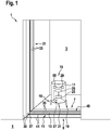
- Fig. 1 shows an elevator arrangement 1 with an elevator car 3 being stopped at a landing 5 at one of multiple floors in a building.
- the elevator car 3 may be closed with an elevator door 31 having for example two elevator door blades 33 which are guided by elevator door rails 35.
- an access to the elevator car 3 may additionally be closed with a landing door 37 having for example two landing door blades 39 which are guided by landing door rails 41.
- a ground surface of the elevator car 3 forms a car sill 7, whereas a ground surface of the landing 5 forms a landing sill 9.
- a step 49 may be formed between the car sill 7 and the landing sill 9 at a transition area 11 where a gap 13 extends between the car sill 7 and the landing sill 9.
- step 49 has a substantial height, it may form an obstacle for passengers entering or exiting the elevator car 3.
- the height of the step 49 was determined by a technician in order to then suitably align the elevator car 3 with the landing 5.
- a specific robot 15 which is configured for executing a method for determining the height of an elevator step 49 in an elevator arrangement 1.
- the robot 15 comprises a support structure 17 such as a housing. At the support structure 17, at least two drive wheels 19 are fixed in a rotatable manner. In the example shown, the robot 15 comprises exactly two drive wheels 19. The drive wheels 19 are arranged at opposite lateral sides of the support structure 17. Each drive wheel 19 is fixed to the support structure 17 at a fixed location relative to the support structure 17.
- the robot 15 comprises additional stabiliser wheels 21 which shall prevent the support structure 17 from excessively inclining.
- one stabiliser wheel 21 is arranged at a front side and another stabiliser wheel 21 is arranged at a rear side of the support structure 17.
- Each stabiliser wheel 21 is fixed to the support structure 17 such that it may be rotated while additionally being vertically displaceable relative to the support structure 17.
- the robot 15 comprises a mobilisation unit 23.
- the mobilisation unit 23 may comprise motors or other actuators for driving each of the drive wheels 19.
- each drive wheel 19 may be driven independent from the other drive wheel 19.
- the robot 15 may be displaced in linear motions as well as in curved or rotating motions along a ground surface within the elevator car 3 and the landing 5.
- An operation of the mobilisation unit 23 is controlled by a controller 25.
- the controller 25 may control displacing the robot 15 within accessible areas within the building by instructing the mobilisation unit 23.
- the controller 25 may for example receive navigation data provided by a navigation unit 29.
- Such navigation data may include information about a current position of the robot 15 within the building as well as information about the accessible areas within the building.
- the robot 15 comprises a cliff sensor 27.
- the cliff sensor 27 is configured for detecting a cliff at the ground surface underneath the cliff sensor 27.
- the cliff sensor 27 may be configured for determining a current distance to this ground surface and the cliff sensor 27 may detect the cliff upon detecting an occurrence of a sudden substantial difference in such distance.
- the cliff sensor 27 may for example comprise a light emitter or, more specifically, a laser emitter for emitting light pulses and a light detector for detecting the light pulses upon being reflected at a target such as the ground surface.
- the cliff sensor 27 is fixed to the support structure 17 at a predetermined position with respect to the positions of the drive wheels 19. Accordingly, upon detecting a cliff with the cliff sensor 27, a current position of the drive wheels 19 with respect to this cliff may be precisely known.
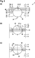
- Figs. 2(a) - (c) visualise schematic top views of the robot 15 in the elevator arrangement 1 during a sequence of method steps with which the robot 15 may determine the height of the elevator step 49 between the car sill 7 of the elevator car 3 and the landing sill 9 of the landing 5.
- Fig. 3 shows a side view of a situation in which the robot 15 has been displaced to a position on top of the elevator step 49 such as to enable measuring the height h of the elevator step 49.
- the robot 15 is first displaced towards the transition area 11, i.e. in a direction towards the landing 5.
- the robot 15 may originally be located outside the elevator car, i.e. at the landing 5, and may then be displaced towards the transition area 11, i.e. in a direction towards the elevator car 3.
- the robot 15 Upon approaching and reaching the transition area 11, the robot 15 is displaced such that at least a portion of the robot crosses the gap 13 between the car sill 7 and the landing sill 9. For example, as shown in Fig. 2(a) , a front side at which the front sided stabilisation wheel 21 is fixed, may cross the gap 13. The robot 15 is further displaced until reaching a first position at which the cliff sensor 27 detects the gap 13, as shown in Fig. 2(a) .
- the cliff sensor 27 may be arranged at the robot 15 such as to form an outermost portion at a circumference of the robot 15, in particularly in displacement direction of the robot.
- the cliff sensor 27 itself is the portion of the robot 15 which crosses the gap 13, thereby detecting the gap 13 underneath itself while the robot 15 has already reached its first position.
- the controller 25 may know that the "cliff" detected in such situation by the cliff sensor 27 is in fact no edge of a step of stairs or an edge at a lateral limit of the landing 5 but is the gap 13 extending between the landing sill 9 and the car sill 7. Based on this knowledge, the controller 25 may decide to further displace the robot 15. Particularly, the robot 15 may be further displaced in a linear motion direction 51 towards the landing 5, preferably in a direction being rectangular to an extension direction of the gap 13. Therein, the robot 15 may preferably be displaced by a distance which corresponds to the pre-known distance d between the cliff sensor 27 and a virtual line 57 connecting the drive wheels 19. Accordingly, the robot arrives at a position, shown in Fig. 2(b) , where both of its drive wheels 19 are arranged at or close to the gap 13.
- the robot 15 may be displaced to a final configuration referred to as second position, as shown in Fig. 2(c) and Fig. 3 , where one drive wheel 19' of its two drive wheels 19 stands on the landing sill 9 whereas the other drive wheel 19" of the two drive wheels 19 stands on the car sill 7.
- displacing is established by turning the robot 15 around a vertical rotation axis 45 in a rotation direction 53 by approximately 90°.
- the robot 15 is positioned and oriented such that the virtual line 57 connecting both drive wheels 19 extends in a direction being rectangular to an extension direction of the gap 13.
- a sum of a distance from the landing-side drive wheel 19' to the gap 13 and a distance from the car-side drive wheel 19" to the gap 13 is at a maximum. Furthermore, in the example shown, the positions of both drive wheels 19 are approximately symmetric with respect to the gap 13, i.e. both mentioned distances are equal.
- the process of displacing the robot 15 from the first position, as shown in Fig. 2(a) , to the second position, as shown in Fig. 2(c) is established taking into account the predetermined relative position of the cliff sensor 27 with respect to the two drive wheels 19 of the robot 15.
- this knowledge may be used for suitably and precisely displacing the robot 15 from the first position, where its cliff sensor 17 detects the gap 13, to the final configuration at the second position, where both of the drive wheels 19 are standing at opposite sides of the gap 13, preferably in a symmetric arrangement.
- the tilt angle 47 of the support structure 17 of the robot 15 may be measured.
- Such tilt angle 47 is established between the vertical axis 45 of the robot and an absolute vertical axis 43 corresponding to a gravity direction.
- the tilt angle 47 may be measured using an acceleration sensor 55 included in the robot 15.
- Such acceleration sensor 55 may serve as an orientation sensor.
- the height h of the step 49 may be determined based on the measured tilt angle 47 and taking into account the relative positions of the two drive wheels 19 with respect to the gap 13. Specifically, the height h of the step 49 may the calculated based on the measured tilt angle 47 and the known lateral distance of the drive wheels 19 from the gap 13.
- the method and the robot 15 proposed herein allow determining the height h of the step 49 in a highly automatic manner and with a high precision and reliability.
- the robot 15 may only require hardware which is already present for other purposes.
- the cliff sensor 27 may be used for precisely positioning the robot 15 within the transition area 11, i.e. relative to the gap 13, such cliff sensor 27 being generally provided for such types of robot 15 for other purposes, anyway.
- the elevator cabin should be marked on a map that is used by the robot to navigate inside the building, so that the robot may use the cliff sensor just to refine its position on the elevator step. At least a point inside the cabin should be recorded. Afterwards, the robot moves towards the cabin until it perceives a cliff (e.g. >10 cm), corresponding to the gap between the floor and the cabin. At that point, knowing the distance between its centre and the cliff sensor, the robot moves forward by this distance and then performs a 90° rotation to have one lateral wheel in the cabin and one still on the floor. At this point, the levelling can be computed with the orientation sensor.
- a cliff e.g. >10 cm
Landscapes
- Engineering & Computer Science (AREA)
- Automation & Control Theory (AREA)
- Computer Networks & Wireless Communication (AREA)
- Manipulator (AREA)
Priority Applications (1)
| Application Number | Priority Date | Filing Date | Title |
|---|---|---|---|
| EP20159906.5A EP3872015A1 (de) | 2020-02-27 | 2020-02-27 | Verfahren und roboter zur bestimmung einer höhe einer aufzugsstufe in einer aufzugsanordnung |
Applications Claiming Priority (1)
| Application Number | Priority Date | Filing Date | Title |
|---|---|---|---|
| EP20159906.5A EP3872015A1 (de) | 2020-02-27 | 2020-02-27 | Verfahren und roboter zur bestimmung einer höhe einer aufzugsstufe in einer aufzugsanordnung |
Publications (1)
| Publication Number | Publication Date |
|---|---|
| EP3872015A1 true EP3872015A1 (de) | 2021-09-01 |
Family
ID=69742835
Family Applications (1)
| Application Number | Title | Priority Date | Filing Date |
|---|---|---|---|
| EP20159906.5A Withdrawn EP3872015A1 (de) | 2020-02-27 | 2020-02-27 | Verfahren und roboter zur bestimmung einer höhe einer aufzugsstufe in einer aufzugsanordnung |
Country Status (1)
| Country | Link |
|---|---|
| EP (1) | EP3872015A1 (de) |
Cited By (4)
| Publication number | Priority date | Publication date | Assignee | Title |
|---|---|---|---|---|
| CN117645215A (zh) * | 2022-09-05 | 2024-03-05 | 株式会社日立大厦系统 | 电梯系统以及电梯控制方法 |
| JP7567077B1 (ja) | 2024-01-17 | 2024-10-15 | 東芝エレベータ株式会社 | エレベータ自律移動体連携システム |
| JP7625752B1 (ja) | 2024-06-12 | 2025-02-03 | 東芝エレベータ株式会社 | エレベータ自律移動体連携システム |
| CN120024767A (zh) * | 2025-02-27 | 2025-05-23 | 上海三菱电梯有限公司 | 电梯平层误差检测方法 |
Citations (3)
| Publication number | Priority date | Publication date | Assignee | Title |
|---|---|---|---|---|
| JP2005089046A (ja) * | 2003-09-16 | 2005-04-07 | Matsushita Electric Works Ltd | 自律移動車両におけるエレベータ制御システム |
| WO2007047510A2 (en) * | 2005-10-14 | 2007-04-26 | Aethon, Inc. | Robotic inventory management |
| WO2018198224A1 (ja) | 2017-04-26 | 2018-11-01 | 三菱電機株式会社 | エレベーターの段差点検装置 |
-
2020
- 2020-02-27 EP EP20159906.5A patent/EP3872015A1/de not_active Withdrawn
Patent Citations (3)
| Publication number | Priority date | Publication date | Assignee | Title |
|---|---|---|---|---|
| JP2005089046A (ja) * | 2003-09-16 | 2005-04-07 | Matsushita Electric Works Ltd | 自律移動車両におけるエレベータ制御システム |
| WO2007047510A2 (en) * | 2005-10-14 | 2007-04-26 | Aethon, Inc. | Robotic inventory management |
| WO2018198224A1 (ja) | 2017-04-26 | 2018-11-01 | 三菱電機株式会社 | エレベーターの段差点検装置 |
Cited By (6)
| Publication number | Priority date | Publication date | Assignee | Title |
|---|---|---|---|---|
| CN117645215A (zh) * | 2022-09-05 | 2024-03-05 | 株式会社日立大厦系统 | 电梯系统以及电梯控制方法 |
| JP7567077B1 (ja) | 2024-01-17 | 2024-10-15 | 東芝エレベータ株式会社 | エレベータ自律移動体連携システム |
| JP2025111068A (ja) * | 2024-01-17 | 2025-07-30 | 東芝エレベータ株式会社 | エレベータ自律移動体連携システム |
| JP7625752B1 (ja) | 2024-06-12 | 2025-02-03 | 東芝エレベータ株式会社 | エレベータ自律移動体連携システム |
| JP2025186748A (ja) * | 2024-06-12 | 2025-12-24 | 東芝エレベータ株式会社 | エレベータ自律移動体連携システム |
| CN120024767A (zh) * | 2025-02-27 | 2025-05-23 | 上海三菱电梯有限公司 | 电梯平层误差检测方法 |
Similar Documents
| Publication | Publication Date | Title |
|---|---|---|
| US10266097B2 (en) | Traveling vehicle and method of controlling the traveling vehicle | |
| JP6258626B2 (ja) | 自律移動装置およびその制御方法 | |
| US11913775B2 (en) | Intra-hoistway measurement system | |
| JP4224029B2 (ja) | 移動ロボット | |
| US10362917B2 (en) | Cleaning robot | |
| AU2014357957B2 (en) | Cleaning robot and control method thereof | |
| JP2006146376A (ja) | 自立移動ロボット及び移動不能領域検出方法 | |
| CN103086215B (zh) | 层间间距调整式双层电梯 | |
| JPH0218295A (ja) | コンテナクレーン装置並びにコンテナクレーン装置の運転法 | |
| JP2017128440A (ja) | エレベーター用点検装置及びエレベーター用点検システム | |
| JP5124266B2 (ja) | 階段昇降機 | |
| JP2005216022A (ja) | 自律走行ロボットクリーナー | |
| CN105173952B (zh) | 电梯的控制装置和电梯的控制方法 | |
| JP2008179432A (ja) | エレベータの位置検出装置 | |
| JP2005089046A (ja) | 自律移動車両におけるエレベータ制御システム | |
| JP5481513B2 (ja) | エレベータ | |
| JP4869790B2 (ja) | エレベータのかご位置検出装置 | |
| KR20020080900A (ko) | 로봇 청소기의 장애물 감지 장치 및 그 방법 | |
| CN120024767A (zh) | 电梯平层误差检测方法 | |
| EP4299499A1 (de) | Treppenliftvorrichtung, der einen kollisionsverhinderer umfasst, sowie verfahren zur kollisionsverhinderung und verwendung | |
| KR102706973B1 (ko) | 자기센서를 이용한 위치 검출 시스템 및 방법 | |
| JP2020198048A (ja) | 車両制御装置及び車両制御方法 | |
| KR102182981B1 (ko) | 엘리베이터 카 위치 검출 시스템 | |
| US20240083712A1 (en) | Elevator landing control system | |
| JP2008129899A (ja) | 自走式移動体 |
Legal Events
| Date | Code | Title | Description |
|---|---|---|---|
| PUAI | Public reference made under article 153(3) epc to a published international application that has entered the european phase |
Free format text: ORIGINAL CODE: 0009012 |
|
| STAA | Information on the status of an ep patent application or granted ep patent |
Free format text: STATUS: THE APPLICATION HAS BEEN PUBLISHED |
|
| AK | Designated contracting states |
Kind code of ref document: A1 Designated state(s): AL AT BE BG CH CY CZ DE DK EE ES FI FR GB GR HR HU IE IS IT LI LT LU LV MC MK MT NL NO PL PT RO RS SE SI SK SM TR |
|
| STAA | Information on the status of an ep patent application or granted ep patent |
Free format text: STATUS: THE APPLICATION IS DEEMED TO BE WITHDRAWN |
|
| 18D | Application deemed to be withdrawn |
Effective date: 20220302 |