EP3872980A1 - Fonction d'équilibre de puissance contre les délestages accidentels - Google Patents
Fonction d'équilibre de puissance contre les délestages accidentels Download PDFInfo
- Publication number
- EP3872980A1 EP3872980A1 EP21157286.2A EP21157286A EP3872980A1 EP 3872980 A1 EP3872980 A1 EP 3872980A1 EP 21157286 A EP21157286 A EP 21157286A EP 3872980 A1 EP3872980 A1 EP 3872980A1
- Authority
- EP
- European Patent Office
- Prior art keywords
- power
- load
- target generator
- target
- generator
- Prior art date
- Legal status (The legal status is an assumption and is not a legal conclusion. Google has not performed a legal analysis and makes no representation as to the accuracy of the status listed.)
- Granted
Links
Images


Classifications
-
- H—ELECTRICITY
- H02—GENERATION; CONVERSION OR DISTRIBUTION OF ELECTRIC POWER
- H02P—CONTROL OR REGULATION OF ELECTRIC MOTORS, ELECTRIC GENERATORS OR DYNAMO-ELECTRIC CONVERTERS; CONTROLLING TRANSFORMERS, REACTORS OR CHOKE COILS
- H02P9/00—Arrangements for controlling electric generators for the purpose of obtaining a desired output
-
- G—PHYSICS
- G01—MEASURING; TESTING
- G01R—MEASURING ELECTRIC VARIABLES; MEASURING MAGNETIC VARIABLES
- G01R31/00—Arrangements for testing electric properties; Arrangements for locating electric faults; Arrangements for electrical testing characterised by what is being tested not provided for elsewhere
- G01R31/34—Testing dynamo-electric machines
Definitions
- the present invention relates to the technical of power engineering, and in particular relates to a generator load state detection method and device and a computer-readable medium.
- a generator is a machine which can convert energy in other forms into electric energy.
- the power receiving system serving as the load of the generator is connected to the generator with cables, the generator transmits the electric energy to the power receiving system through the cables, and the power receiving system utilizes or retransmits the received electric energy.
- the generator in the power transmission system has two different control modes: load control mode and speed control mode.
- the generator in load control mode is responsible for steadily outputting a power
- the generator in speed control mode is responsible for adjusting the output power according to the load.
- the generator For the generator running in load control mode, when a fault of the power receiving system causes an unexpected interruption of the generator load, the generator will still run in load control mode because the generator is unable to obtain a response to the interruption of load. However, since the load power output by the generator is reduced, the generator will increase the rotational speed, expecting to achieve preset target output power. In this case, the power and the rotational speed of the generator are both increased. When the rotational speed of the generator exceeds a preset speed threshold, the over-speed protection function is triggered and the power and the rotational speed of the generator are both reduced. After the rotational speed of the generator is so reduced that the over-speed protection function is terminated, the generator will increase the rotational speed, expecting to achieve the target output power.
- the generator load state detection method and device and the computer-readable medium provided by the present invention for this reason can accurately detect whether the load of a generator is unexpectedly interrupted.
- the embodiments of the present invention provide a generator load state detection method, which comprises:
- acquiring the load power of a target generator comprises:
- determining the load state of the target generator according to the power imbalance value comprises:
- condition 2 comprises: determining whether the target generator changes from the normal running state to the low power state and whether the time the target generator maintains in the low power state exceeds a preset time threshold.
- the method further comprises:
- condition 5 comprises: determining whether a negative sequence voltage or a zero sequence voltage happens to the output end of the target generator, and if Yes, determining that a fault happens to the target generator.
- condition 4 comprises:
- the generator load state detection method further comprises: sending the indication information if the determination results of conditions 3, 4 and 5 are all No.
- a generator load state detection device which comprises:
- the load power acquisition module comprises:
- the load state detection module is used to acquire the determination results of the following two conditions and determine that an unexpected interruption happens to the target generator if the determination results of the following two conditions are both Yes; condition 1: determine whether the power imbalance value is greater than a power balance threshold; condition 2: determine whether the target generator changes from a normal running state to a low load power state.
- the load state detection module is used to determine whether the target generator changes from the normal running state to the low power state and whether the time the target generator maintains in the low power state exceeds a preset time threshold when acquiring the determination result of condition 2.
- the generator load state detection device further comprises:
- condition determination module is used to determine whether a negative sequence voltage or a zero sequence voltage happens to the output end of the target generator when acquiring the determination result of condition 5, and if Yes, determine that a fault happens to the target generator.
- the condition determination module is used to determine whether a disconnection happens to at least one of the following circuits: voltage measuring circuit and current measuring circuit when acquiring the determination result of condition 4, and to determine that the signal acquisition function of the target generator is abnormal if the determination result is Yes, wherein the voltage measuring circuit is used to determine the positive sequence voltage of the output end of the target generator, the current measuring circuit is used to determine the positive sequence current of the output end of the target generator, and the positive sequence voltage and the positive sequence current are used to determine the load power.
- condition determination module is used to send the indication information when the acquired determination results of conditions 3, 4 and 5 are all No.
- the embodiments of the present invention further provide another generator load state detection device, which comprises at least one memory and at least one processor, wherein the at least one memory is used to store a machine-readable program; the at least one processor is used to invoke the machine-readable program to execute the method provided by the first aspect or provided by any possible implementation mode of the first aspect.
- the embodiments of the present invention further provide a computer-readable medium.
- Computer instructions are stored in the computer-readable medium.
- the processor executes the method provided by the first aspect or any possible implementation mode of the first aspect.
- the load power is used to represent the actual output power of a target generator
- the target output power is used to represent the power required by the target generator to output in load control mode
- the difference between the load power and the target output power is calculated as a power imbalance value after the load power and the target output power of the target generator are acquired. Since the load power of the target generator in the case of no unexpected load interruption of the generator is close to the target output power and the load power is greatly different from the target output power in the case of an unexpected load interruption of the generator, an unexpected load interruption of the target generator can be determined according to the power imbalance value.
- an unexpected load interruption of the target generator is determined according to the power imbalance value, it is unnecessary to compare a plurality of parameter thresholds with acquired parameter values, avoiding an inaccurate load state detection of the target generator caused by inaccurate determinations of parameter thresholds. Thus, an unexpected load interruption of the target generator can be determined more accurately.
- the load power is used to represent the actual output power of a target generator
- the target output power is used to represent the power required by the target generator to output in load control mode.
- the difference between the load power and the target output power is determined as a power imbalance value.
- the load power of the target generator in the case of no unexpected load interruption of the generator is close to the target output power and the load power is greatly different from the target output power in the case of an unexpected load interruption of the generator.
- an unexpected load interruption of the target generator can be determined according to the power imbalance value. Since the accurate load power and target output power can be obtained, it is unnecessary to determine a great number of parameter thresholds for comparisons. Thus, an unexpected load interruption of the target generator can accurately be detected according to the calculated power imbalance value.
- the embodiments of the present invention provide a generator load state detection method and the method comprises the following steps:
- the load power is used to represent the actual output power of a target generator
- the target output power is used to represent the power required by the target generator to output in load control mode
- the difference between the load power and the target output power is calculated as a power imbalance value after the load power and the target output power of the target generator are acquired. Since the load power of the target generator in the case of no unexpected load interruption of the generator is close to the target output power and the load power is greatly different from the target output power in the case of an unexpected load interruption of the generator, an unexpected load interruption of the target generator can be determined according to the power imbalance value.
- an unexpected load interruption of the target generator is determined according to the power imbalance value, it is unnecessary to compare a plurality of parameter thresholds with acquired parameter values, avoiding an inaccurate load state detection of the target generator caused by inaccurate determinations of parameter thresholds. Thus, an unexpected load interruption of the target generator can be determined more accurately.
- the load states of the target generator include unexpected load interruption and no unexpected load interruption.
- An unexpected load interruption means that a load interruption happens before the target generator obtains the corresponding instruction or feedback, that is to say, the load already stops fetching electric energy, but the target generator does not know a load interruption and still produces electric energy in load control mode.
- No unexpected load interruption means that no load interruption of the target generator happens or the target generator already obtains the corresponding instruction or feedback before a load interruption happens, that is to say, the load normally fetches electric energy from the target generator or the target generator knows a load interruption and the load already stops fetching electric energy.
- the target generator when the target generator is in load control mode, the target generator will steadily output a power according to the target output power under the control of the control system, and normally, the load power and the target output power of the target generator will not fluctuate greatly. Only in this case, an unexpected load interruption of the target generator can be determined according to the difference between the load power and the target output power. If the target generator is in speed control mode, the control system in the power plant will adjust the target output power of the generator in real time according to the load of the power system. Therefore, the generator in speed control mode is unable to determine an unexpected load interruption according to the difference between the load power and the target output power.
- a single line is usually connected between the target generator and a load, and the target generator is connected to only one load, that is to say, only a set of cables transmitting electric energy is included between the target generator and the load.
- the target generator transmits electric energy to the load through the set of cables.
- the target generator is unable to transmit electric energy to the load, or when any outgoing line of the set of cables is disconnected, the target generator is unable to transmit electric energy to the load, either.
- the load is interrupted, the electric energy output by the target generator is unable to reach the load.
- the generator is connected to a plurality of loads or the generator is connected to a load through a plurality of sets of cables, when one load is interrupted or a set of cables is disconnected, the generator can still transmit electric energy to other loads or transmits electric energy through other cables. In this case, a little difference exists between the load power and the target output power, and therefore, it is hard to detect whether a load of the generator is interrupted according to the power imbalance value.
- the target output power of the target generator when the target output power of the target generator is acquired, the target output power is usually a fixed value or a slowly-changing value since the target generator is in load control mode. Therefore, the target output power can be acquired from the control system of the generator according to the preset data acquisition period.
- the target output power of the target generator may be acquired from the control system of the power plant by a 4-20 mA transformer.
- the target output power of the target generator can be stored in advance, and when it is necessary to calculate the power imbalance value, the target output power stored in advance can directly be read, without any necessity of acquiring the target output power of the target generator from the control system of the generator in real time or periodically.
- the positive sequence voltage and positive sequence current of the output end of the target generator can be acquired, and then the load power of the target generator can be determined according to the acquired positive sequence voltage and positive sequence current.
- the method of acquiring the load power of the target generator may comprise the following steps:
- the positive sequence voltage and positive sequence current of the output end of the target generator are determined, and then the load power of the target generator can be calculated according the real parts and imaginary parts of the positive sequence voltage and the positive sequence current.
- the calculation of the load power of the target generator only by determining the positive sequence voltage and the positive sequence current guarantees the convenience of acquiring the load power.
- the calculation of the load power of the target generator according to the positive sequence voltage and the positive sequence current guarantees the accuracy of the calculated load power and then guarantees the accuracy of the detection of the load state of the target generator.
- the positive sequence voltage of the output end of the target generator may be obtained by calculating the voltages measured by a potential transformer (PT), and the positive sequence current of the output end of the target generator may be obtained by calculating the currents measured by a current transformer (CT).
- PT potential transformer
- CT current transformer
- the positive sequence voltage and the positive sequence current of the output end of the target generator may be measured by other types of transformers or measuring circuits.
- step 104 of determining the load state of the target generator according to the power imbalance value may be realized in the following way:
- condition 1 During the normal electric energy transmission of the target generator to the load, the target generator transmits electric energy according to the given target output power under the control of the control system of the generator, and the load power of the target generator is close to the target output power. In this case, the power imbalance value is small.
- the load of the target generator is unexpectedly interrupted, the target output power of the target generator remains unchanged, while the load power of the target generator is reduced greatly. In this case, the power imbalance value is large.
- a power balance threshold may be preset and the power imbalance value may be compared with the power balance threshold.
- An unexpected load interruption of the target generator possibly happens when the power imbalance value is greater than the power balance threshold, that is to say, the power imbalance value being greater than the power balance threshold is one of the basic conditions for an unexpected load interruption of the target generator.
- the power imbalance value is used to measure the difference between the target output power and the load power. Therefore, the absolute value of the difference between the target output power and the load power may be determined as a power imbalance value.
- the power imbalance value may be determined according to the rated power of the target generator, and may be 30% of the rated power, for example.
- the load power of the target generator is reduced so greatly that the load power of the target generator is less than the corresponding threshold and the target generator changes from a normal running state to a low load power state.
- the normal running state refers to a state in which the target generator runs normally.
- a threshold may be preset and if the load power is greater than the threshold, it is considered that the target generator is in the normal running state. Details are omitted.
- a low load power state refers to a state in which the target generator runs at a low load power, that is to say, the load power of the target generator is less than a certain threshold.
- An unexpected load interruption of the target generator will cause the target generator to change to the low load power state.
- a load fluctuation of the target generator or other reasons may also cause the target generator to change to the low load power state.
- the low load power state caused by a load fluctuation or other reasons is temporary, that is to say, after the load power of the target generator is temporarily less than the corresponding threshold, it will return to the normal level.
- the low load power state caused by an unexpected load interruption of the target generator is continuous, that is say, after the load of the target generator is unexpectedly interrupted, and the load power of the target generator will continuously be less than the corresponding threshold.
- the low load power state caused by a load fluctuation and other reasons can be ruled out according to whether the time the target generator maintains in the low load power state is greater than a preset time threshold, and the accuracy of the detection of the load state of the target generator can be guaranteed. That is say, after the target generator runs from the normal running state to the low load power state and the low load power state is maintained for a period of time, it is determined that the target generator changes from the normal running state to the low load power state.
- an unexpected load interruption can finally be determined. For example, after determining the power imbalance value is continuously greater than the power balance threshold, determine the determination result of condition 1 is Yes, or after determining the target generator changes from the normal running state to the low load power state and the time the target generator maintains in the low load power state is exceeds a preset time threshold, determine the result of condition 2 is Yes.
- Figs. 4 and 5 show the trend of the changes of the load power and frequency of the target generator after an unexpected load interruption and the trend of the changes of the load power and frequency of the target generator in load control mode, respectively.
- the trend of the changes of the load power and frequency of the target generator after an unexpected load interruption and the trend of the changes of the load power and frequency of the target generator running normally in load control mode are described respectively below.
- the load power decreases from PL1 to PL2, as indicated by arrow 1; later, the load power increases according to the new power frequency characteristic curve (PL2) to expect to reach a new balance state (the intersection point of PL2 with PG is the new balance state point and PG represents the characteristic curve of the target output frequency), as indicated by arrow 2; after the rotational speed of the target generator exceeds the speed threshold, the over-speed control function takes effect, the rotational speed of the target generator is reduced, and the load power and frequency of the target generator are both reduced, as indicated by arrow 3; after the rotational speed of the target generator is reduced to the speed threshold for ending over-speed control, the target generator again increases the load power in load control mode, as indicated by arrow 2; thus the steps indicated by arrows 2 and 3 are alternately and cyclically performed, causing oscillations of the target generator.
- PL2 new power frequency characteristic curve
- the load power increases according to the new power frequency characteristic curve (PL2), as indicated by arrow 2, because the control system of the generator is unable to respond in time.
- the generator in speed control mode in the power supply system reduces the load power because of too high a rated frequency
- the target generator in load control mode will increase the load power. Since the output load power is still less than the target output power, the frequency of the target generator is continuously but very slowly increased, as indicated by arrow 3.
- the load power of the target generator is equal to the target output power at point A, the frequency of the target generator exceeds the rated frequency.
- the generator in speed control mode in the power supply system will still reduce the output load power because of too high a rated frequency, and therefore, the target generator in load control mode will continue to increase the output load power. However, since the output load power is higher than the target output power, the frequency of the target generator starts to decrease, as indicated by arrow 4. Finally, the output load power of the target generator returns to PG (fn) and the frequency of the target generator returns to the rated frequency to satisfy the previous power balance state again.
- corresponding indication information will be sent to other components and the other components may perform corresponding operations after receiving the indication information, for example, send trip information to the switch of the target generator so that the switch is tripped.
- the signal acquisition function of the generator is abnormal or the target generator itself is faulty, even if the determination results of conditions 1 and 2 are both Yes in some case, no unexpected load interruption actually happens.
- Step 301 acquire the determination results of the following conditions and determine whether to send information indicating that an unexpected load interruption happens to the target generator according to the determination results. If at least one of the determination results is Yes, go to step 302, and otherwise go to step 303.
- condition 3 determine whether a system oscillation happens to the system where the target generator is located;
- condition 4 determine whether the signal acquisition function of the target generator is abnormal;
- condition 5 determine whether a fault happens to the target generator.
- condition 3 determine whether a system oscillation is detected. How to detect a system oscillation belongs to the prior art and is not described again here.
- condition 4 determine whether a fault happens to at least one of the following circuits: voltage measuring circuit and current measuring circuit, wherein the voltage measuring circuit is used to determine the positive sequence voltage of the output end of the target generator, the current measuring circuit is used to determine the positive sequence current of the output end of the target generator, and the positive sequence voltage and the positive sequence current are used to determine the load power; determine that the signal acquisition function of the target generator is abnormal if the determination result is Yes.
- condition 5 determine whether a negative sequence voltage or a zero sequence voltage happens to the output end of the target generator, and if Yes, determine that a fault happens to the target generator. How to acquire the negative sequence voltage or zero sequence voltage of the output end of the target generator belongs to the prior art and is not described again here.
- the load power of the target generator may continuously be less than the corresponding power threshold, that is to say, the power imbalance value is greater than the power balance threshold and the time the target generator runs in the low load state is greater than the time threshold. Since the power imbalance value is determined according to the parameters acquired from the target generator, for example, according to the positive sequence voltage and positive sequence current acquired from the output end of the target generator, if the signal acquisition function of the target generator is abnormal, the acquired parameters used to determine the power imbalance value are inaccurate. Therefore, the power imbalance value determined according to the acquired parameters is also inaccurate, thus causing the acquired power imbalance value to be greater than the power balance threshold and the time the target generator runs in the low power state to be greater than the time threshold. However, the load power of the target generator is actually no less than the corresponding power threshold.
- Step 302 Forbid sending indication information.
- Step 303 Send indication information to the external device.
- the accuracy of the determination of an unexpected load interruption of the target generator can be improved and mis-operations can be avoided.
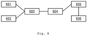
- a generator load state detection device which comprises:
- the load power acquisition module 601 may be used to perform step 101 in the embodiment of the above-mentioned method
- the target power acquisition module 602 may be used to perform step 102 in the embodiment of the above-mentioned method
- the parameter calculation module 603 may be used to perform step 103 in the embodiment of the above-mentioned method
- the load state detection module 604 may be used to perform step 104 in the embodiment of the above-mentioned method.
- the load power acquisition module 601 comprises:
- the information acquisition unit 6011 may be used to perform step 201 in the embodiment of the above-mentioned method
- the management and calculation unit 6012 may be used to perform step 202 in the embodiment of the above-mentioned method.
- the load state detection module 604 is used to acquire the determination results of the following two conditions and determine that an unexpected interruption happens to the target generator if the determination results of the following two conditions are both Yes; condition 1: determine whether the power imbalance value is greater than a power balance threshold; condition 2: determine whether the target generator changes from a normal running state to a low load power state.
- the load state detection module 604 is used to determine whether the target generator changes from the normal running state to the low power state and whether the time the target generator maintains in the low power state exceeds a preset time threshold when acquiring the determination result of condition 2.
- the generator load state detection device further comprises:
- condition determination module 605 may be used to perform steps 301 and 303 in the embodiments of the above-mentioned method
- the information interception module 606 may be used to perform step 302 in the embodiment of the above-mentioned method.
- condition determination module 605 is used to determine whether a negative sequence voltage or a zero sequence voltage happens to the output end of the target generator when acquiring the determination result of condition 5, and determine that a fault happens to the target generator if the determination result is Yes.
- the condition determination module 605 is used to determine whether a disconnection happens to at least one of the following circuits: voltage measuring circuit and current measuring circuit when acquiring the determination result of condition 4, and determine that the signal acquisition function of the target generator is abnormal if the termination result is Yes, wherein the voltage measuring circuit is used to determine the positive sequence voltage of the output end of the target generator, the current measuring circuit is used to determine the positive sequence current of the output end of the target generator, and the positive sequence voltage and the positive sequence current are used to determine the load power.
- condition determination module 605 is used to send indication information when the acquired determination results of conditions 3, 4 and 5 are all No.
- generator load state detection device provided in the embodiments of the present invention and the generator load state detection method provided in the above-mentioned embodiments are both based on the conception of one invention.
- specific interactions between the modules and units in the generator load state detection device refer to the description in the above-mentioned method embodiments. These interactions will not be described again here.
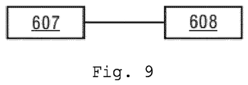
- the embodiments of the present invention provide a generator load state detection device, which comprises at least one memory 607 and at least one processor 608, wherein the at least one storage 607 is used to store a machine-readable program, and the at least one processor 608 is used to invoke machine-readable program stored in the at least one memory 607 to perform the generator load state detection method provided in the above-mentioned embodiments.
- the present invention further provides a computer-readable medium, which stores instructions used to allow a machine to execute the generator load state detection method described in this document.
- a system or device equipped with a storage medium can be provided.
- Software program codes which can realize the function in any of above-mentioned embodiments are stored in the storage medium and the computer (or CPU or MPU) of the system or device can read and execute the program codes stored in the storage medium.
- program codes read from the storage medium themselves can realize the function in any of the above-mentioned embodiments. Therefore, program codes and the storage medium where program codes are stored constitute a part of the present invention.
- Embodiments of the storage medium used to provide program codes include a floppy disk, hard disk, magneto-optical disk, compact disk (for example, compact disk read-only memory (CD-ROM)), compact disk - recordable (CD-R), compact disk - rewritable (CD-RW), digital video disk - read only memory (DVD-ROM), digital versatile disk - random access memory (DVD-RAM), digital versatile disk plus rewritable (DVD+RW), magnetic tape, non-volatile memory card, and read-only memory (ROM).
- the program codes may be downloaded from the server computer over a communication network.
- hardware modules can mechanically or electrically be realized.
- a hardware module can comprise a permanent dedicated circuit or logic (for example, special processor, FPGA, or ASIC) to complete the corresponding operations.
- a hardware module can further comprise a programmable logic or circuit (for example, a general processor or other programmable processor) and can complete the corresponding operations through temporary software setting.
- the specific implementation mode mechanical mode, or dedicated permanent circuit, or circuit which is temporarily set
Landscapes
- Physics & Mathematics (AREA)
- General Physics & Mathematics (AREA)
- Engineering & Computer Science (AREA)
- Power Engineering (AREA)
- Control Of Eletrric Generators (AREA)
Applications Claiming Priority (1)
| Application Number | Priority Date | Filing Date | Title |
|---|---|---|---|
| CN202010098947.6A CN113341316A (zh) | 2020-02-18 | 2020-02-18 | 发电机负载状态检测方法、装置和计算机可读介质 |
Publications (2)
| Publication Number | Publication Date |
|---|---|
| EP3872980A1 true EP3872980A1 (fr) | 2021-09-01 |
| EP3872980B1 EP3872980B1 (fr) | 2023-04-05 |
Family
ID=74661266
Family Applications (1)
| Application Number | Title | Priority Date | Filing Date |
|---|---|---|---|
| EP21157286.2A Active EP3872980B1 (fr) | 2020-02-18 | 2021-02-16 | Fonction d'équilibre de puissance contre les délestages accidentels |
Country Status (2)
| Country | Link |
|---|---|
| EP (1) | EP3872980B1 (fr) |
| CN (1) | CN113341316A (fr) |
Cited By (5)
| Publication number | Priority date | Publication date | Assignee | Title |
|---|---|---|---|---|
| CN115051416A (zh) * | 2022-08-16 | 2022-09-13 | 阿里巴巴(中国)有限公司 | 数据处理方法、发电方法、装置和云设备 |
| CN115327406A (zh) * | 2022-08-02 | 2022-11-11 | 国网江苏省电力有限公司电力科学研究院 | 电池模组在线故障检测方法、装置、存储器及计算设备 |
| CN117028127A (zh) * | 2023-07-26 | 2023-11-10 | 华能澜沧江水电股份有限公司 | 水轮机甩负荷判断方法、判断装置、电子设备和存储介质 |
| CN117811313A (zh) * | 2023-12-29 | 2024-04-02 | 江苏速豹动力科技有限公司 | 运载工具电源控制方法、装置及运载工具 |
| CN119686901A (zh) * | 2025-01-22 | 2025-03-25 | 湖南华意项目管理有限公司 | 一种水电站的控制方法及相关设备 |
Families Citing this family (2)
| Publication number | Priority date | Publication date | Assignee | Title |
|---|---|---|---|---|
| CN116184188A (zh) * | 2022-11-01 | 2023-05-30 | 三一海洋重工有限公司 | 一种发电机组的负载测试方法、装置、系统及起重机 |
| CN118367622B (zh) * | 2024-06-17 | 2024-09-03 | 东莞市昌晖电气工程有限公司 | 一种电力工程的检测装置和方法 |
Citations (3)
| Publication number | Priority date | Publication date | Assignee | Title |
|---|---|---|---|---|
| JP2009159700A (ja) * | 2007-12-26 | 2009-07-16 | Meidensha Corp | 発電機の出力制御装置および制御方法 |
| EP2423464A1 (fr) * | 2010-08-27 | 2012-02-29 | Siemens Aktiengesellschaft | Procédé destiné au réglage d'un turbogénérateur |
| DE102012211719A1 (de) * | 2012-07-05 | 2014-01-09 | Schaeffler Technologies AG & Co. KG | Elektrisch unterstütztes Fahrrad und Verfahren zum Betreiben eines derartigen Fahrrades |
Family Cites Families (17)
| Publication number | Priority date | Publication date | Assignee | Title |
|---|---|---|---|---|
| JPH0824408B2 (ja) * | 1988-10-04 | 1996-03-06 | 三菱電機株式会社 | 発電機の保護装置 |
| RU2016492C1 (ru) * | 1991-03-28 | 1994-07-15 | Всероссийский теплотехнический научно-исследовательский институт | Способ управления режимом работы турбогенератора для предупреждения перегрузки линий связи турбогенератора с энергосистемой и для определения режима работы |
| JPH0711910A (ja) * | 1993-06-24 | 1995-01-13 | Toshiba Corp | 蒸気タービン制御装置 |
| RU2264688C1 (ru) * | 2004-06-24 | 2005-11-20 | Джус Илья Николаевич | Способ регулирования генератора |
| KR20090128073A (ko) * | 2008-06-10 | 2009-12-15 | 상도전기통신 주식회사 | 부하불평형 경보가 가능한 다기능 차단기 및 그 제어 방법 |
| JP2011185106A (ja) * | 2010-03-05 | 2011-09-22 | Toshiba Corp | 複合サイクル発電プラントおよびその運転方法 |
| JP2012197750A (ja) * | 2011-03-22 | 2012-10-18 | Toshiba Corp | 発電プラントおよび発電プラント運転方法 |
| JP2013141369A (ja) * | 2012-01-05 | 2013-07-18 | Toshiba Corp | パワーロードアンバランス検出装置およびパワーロードアンバランス検出方法 |
| AU2012368224B2 (en) * | 2012-01-31 | 2015-02-26 | Schweitzer Engineering Laboratories, Inc. | Systems and methods for blackout protection |
| US9709964B2 (en) * | 2014-07-11 | 2017-07-18 | Cummins Power Generation Ip, Inc. | Genset power control in power systems |
| CN204556746U (zh) * | 2015-03-24 | 2015-08-12 | 天津师范大学 | 一种网络化智能负载识别装置 |
| DE102016110188A1 (de) * | 2016-06-02 | 2017-12-07 | Rwe International Se | Verfahren zum Betreiben eines elektrischen Verteilnetzes |
| EP3474029B1 (fr) * | 2016-06-21 | 2022-03-30 | Mitsubishi Electric Corporation | Dispositif de détection d'anomalie de charge |
| CN106682705B (zh) * | 2017-02-04 | 2019-12-24 | 武汉阿帕科技有限公司 | 负载特性的识别方法及装置 |
| CN107202669A (zh) * | 2017-05-31 | 2017-09-26 | 广东威灵电机制造有限公司 | 负载不平衡检测方法、装置及计算机可读存储介质 |
| CN107797047B (zh) * | 2017-09-27 | 2020-07-17 | 深圳和而泰智能控制股份有限公司 | 负载状态检测方法、装置及电子设备 |
| CN109698653B (zh) * | 2019-02-28 | 2024-01-09 | 苏州科技大学 | 一种基于透射测速的小型汽油发电机调速控制方法 |
-
2020
- 2020-02-18 CN CN202010098947.6A patent/CN113341316A/zh active Pending
-
2021
- 2021-02-16 EP EP21157286.2A patent/EP3872980B1/fr active Active
Patent Citations (3)
| Publication number | Priority date | Publication date | Assignee | Title |
|---|---|---|---|---|
| JP2009159700A (ja) * | 2007-12-26 | 2009-07-16 | Meidensha Corp | 発電機の出力制御装置および制御方法 |
| EP2423464A1 (fr) * | 2010-08-27 | 2012-02-29 | Siemens Aktiengesellschaft | Procédé destiné au réglage d'un turbogénérateur |
| DE102012211719A1 (de) * | 2012-07-05 | 2014-01-09 | Schaeffler Technologies AG & Co. KG | Elektrisch unterstütztes Fahrrad und Verfahren zum Betreiben eines derartigen Fahrrades |
Cited By (5)
| Publication number | Priority date | Publication date | Assignee | Title |
|---|---|---|---|---|
| CN115327406A (zh) * | 2022-08-02 | 2022-11-11 | 国网江苏省电力有限公司电力科学研究院 | 电池模组在线故障检测方法、装置、存储器及计算设备 |
| CN115051416A (zh) * | 2022-08-16 | 2022-09-13 | 阿里巴巴(中国)有限公司 | 数据处理方法、发电方法、装置和云设备 |
| CN117028127A (zh) * | 2023-07-26 | 2023-11-10 | 华能澜沧江水电股份有限公司 | 水轮机甩负荷判断方法、判断装置、电子设备和存储介质 |
| CN117811313A (zh) * | 2023-12-29 | 2024-04-02 | 江苏速豹动力科技有限公司 | 运载工具电源控制方法、装置及运载工具 |
| CN119686901A (zh) * | 2025-01-22 | 2025-03-25 | 湖南华意项目管理有限公司 | 一种水电站的控制方法及相关设备 |
Also Published As
| Publication number | Publication date |
|---|---|
| CN113341316A (zh) | 2021-09-03 |
| EP3872980B1 (fr) | 2023-04-05 |
Similar Documents
| Publication | Publication Date | Title |
|---|---|---|
| EP3872980A1 (fr) | Fonction d'équilibre de puissance contre les délestages accidentels | |
| RU2526844C2 (ru) | Способ и устройство дистанционной защиты от замыканий на землю | |
| JP5497044B2 (ja) | 電力系統における計器用変成器の二次回路を管理する方法及び装置 | |
| US10756571B2 (en) | System and method for stabilizing power system | |
| US7259947B2 (en) | Phase control switching device | |
| US12111359B2 (en) | Method of monitoring joint and contact conditions in an electrical network | |
| US11469589B2 (en) | Zero sequence current based line differential protection solution | |
| US11177645B2 (en) | Systems and methods for improving restricted earth fault protection | |
| US20140002937A1 (en) | Differential protection in electrical power networks | |
| US10797632B2 (en) | Sensitive directional element for generator protection | |
| EP3425767A1 (fr) | Procédé, appareil et support d'informations lisible par ordinateur pour la détection d'îlotage électrique | |
| EP2884291B1 (fr) | Localisation des pannes dans un réseau électrique | |
| US11630145B2 (en) | Intelligent electronic device operation during power swing | |
| CN113363949A (zh) | 一种距离保护方法、装置、计算机设备和存储介质 | |
| CN113067360A (zh) | 一种vsc-lcc混合直流换流器的换相失败抑制方法及系统 | |
| US11114892B2 (en) | Electric power system transducer failure monitor and measurement recovery | |
| WO2022144165A1 (fr) | Détermination de flux résiduel dans un transformateur de courant | |
| US6501631B1 (en) | Method and device for power system protection | |
| CN117559372B (zh) | 小电流接地系统的单相接地保护方法、装置、设备和介质 | |
| US11079255B2 (en) | Angle determination for a generator | |
| KR102435293B1 (ko) | 지능형 전자 장치 | |
| JP7570290B2 (ja) | 接続相推定システム及び接続相推定方法 | |
| CN119044872B (zh) | 一种励磁pt慢熔判别方法 | |
| US20250020735A1 (en) | Method of determining fault of power system | |
| RU192061U1 (ru) | Устройство контроля количества и продолжительности отключений и отклонения напряжения в электрических сетях 0,38 кВ |
Legal Events
| Date | Code | Title | Description |
|---|---|---|---|
| PUAI | Public reference made under article 153(3) epc to a published international application that has entered the european phase |
Free format text: ORIGINAL CODE: 0009012 |
|
| STAA | Information on the status of an ep patent application or granted ep patent |
Free format text: STATUS: REQUEST FOR EXAMINATION WAS MADE |
|
| 17P | Request for examination filed |
Effective date: 20210216 |
|
| AK | Designated contracting states |
Kind code of ref document: A1 Designated state(s): AL AT BE BG CH CY CZ DE DK EE ES FI FR GB GR HR HU IE IS IT LI LT LU LV MC MK MT NL NO PL PT RO RS SE SI SK SM TR |
|
| RBV | Designated contracting states (corrected) |
Designated state(s): AL AT BE BG CH CY CZ DE DK EE ES FI FR GB GR HR HU IE IS IT LI LT LU LV MC MK MT NL NO PL PT RO RS SE SI SK SM TR |
|
| GRAP | Despatch of communication of intention to grant a patent |
Free format text: ORIGINAL CODE: EPIDOSNIGR1 |
|
| STAA | Information on the status of an ep patent application or granted ep patent |
Free format text: STATUS: GRANT OF PATENT IS INTENDED |
|
| INTG | Intention to grant announced |
Effective date: 20221115 |
|
| GRAS | Grant fee paid |
Free format text: ORIGINAL CODE: EPIDOSNIGR3 |
|
| GRAA | (expected) grant |
Free format text: ORIGINAL CODE: 0009210 |
|
| STAA | Information on the status of an ep patent application or granted ep patent |
Free format text: STATUS: THE PATENT HAS BEEN GRANTED |
|
| AK | Designated contracting states |
Kind code of ref document: B1 Designated state(s): AL AT BE BG CH CY CZ DE DK EE ES FI FR GB GR HR HU IE IS IT LI LT LU LV MC MK MT NL NO PL PT RO RS SE SI SK SM TR |
|
| REG | Reference to a national code |
Ref country code: GB Ref legal event code: FG4D |
|
| REG | Reference to a national code |
Ref country code: DE Ref legal event code: R096 Ref document number: 602021001785 Country of ref document: DE |
|
| REG | Reference to a national code |
Ref country code: CH Ref legal event code: EP |
|
| REG | Reference to a national code |
Ref country code: AT Ref legal event code: REF Ref document number: 1559012 Country of ref document: AT Kind code of ref document: T Effective date: 20230415 |
|
| REG | Reference to a national code |
Ref country code: IE Ref legal event code: FG4D |
|
| REG | Reference to a national code |
Ref country code: LT Ref legal event code: MG9D |
|
| REG | Reference to a national code |
Ref country code: NL Ref legal event code: MP Effective date: 20230405 |
|
| REG | Reference to a national code |
Ref country code: AT Ref legal event code: MK05 Ref document number: 1559012 Country of ref document: AT Kind code of ref document: T Effective date: 20230405 |
|
| PG25 | Lapsed in a contracting state [announced via postgrant information from national office to epo] |
Ref country code: NL Free format text: LAPSE BECAUSE OF FAILURE TO SUBMIT A TRANSLATION OF THE DESCRIPTION OR TO PAY THE FEE WITHIN THE PRESCRIBED TIME-LIMIT Effective date: 20230405 |
|
| PG25 | Lapsed in a contracting state [announced via postgrant information from national office to epo] |
Ref country code: SE Free format text: LAPSE BECAUSE OF FAILURE TO SUBMIT A TRANSLATION OF THE DESCRIPTION OR TO PAY THE FEE WITHIN THE PRESCRIBED TIME-LIMIT Effective date: 20230405 Ref country code: PT Free format text: LAPSE BECAUSE OF FAILURE TO SUBMIT A TRANSLATION OF THE DESCRIPTION OR TO PAY THE FEE WITHIN THE PRESCRIBED TIME-LIMIT Effective date: 20230807 Ref country code: NO Free format text: LAPSE BECAUSE OF FAILURE TO SUBMIT A TRANSLATION OF THE DESCRIPTION OR TO PAY THE FEE WITHIN THE PRESCRIBED TIME-LIMIT Effective date: 20230705 Ref country code: ES Free format text: LAPSE BECAUSE OF FAILURE TO SUBMIT A TRANSLATION OF THE DESCRIPTION OR TO PAY THE FEE WITHIN THE PRESCRIBED TIME-LIMIT Effective date: 20230405 Ref country code: AT Free format text: LAPSE BECAUSE OF FAILURE TO SUBMIT A TRANSLATION OF THE DESCRIPTION OR TO PAY THE FEE WITHIN THE PRESCRIBED TIME-LIMIT Effective date: 20230405 |
|
| PG25 | Lapsed in a contracting state [announced via postgrant information from national office to epo] |
Ref country code: RS Free format text: LAPSE BECAUSE OF FAILURE TO SUBMIT A TRANSLATION OF THE DESCRIPTION OR TO PAY THE FEE WITHIN THE PRESCRIBED TIME-LIMIT Effective date: 20230405 Ref country code: PL Free format text: LAPSE BECAUSE OF FAILURE TO SUBMIT A TRANSLATION OF THE DESCRIPTION OR TO PAY THE FEE WITHIN THE PRESCRIBED TIME-LIMIT Effective date: 20230405 Ref country code: LV Free format text: LAPSE BECAUSE OF FAILURE TO SUBMIT A TRANSLATION OF THE DESCRIPTION OR TO PAY THE FEE WITHIN THE PRESCRIBED TIME-LIMIT Effective date: 20230405 Ref country code: LT Free format text: LAPSE BECAUSE OF FAILURE TO SUBMIT A TRANSLATION OF THE DESCRIPTION OR TO PAY THE FEE WITHIN THE PRESCRIBED TIME-LIMIT Effective date: 20230405 Ref country code: IS Free format text: LAPSE BECAUSE OF FAILURE TO SUBMIT A TRANSLATION OF THE DESCRIPTION OR TO PAY THE FEE WITHIN THE PRESCRIBED TIME-LIMIT Effective date: 20230805 Ref country code: HR Free format text: LAPSE BECAUSE OF FAILURE TO SUBMIT A TRANSLATION OF THE DESCRIPTION OR TO PAY THE FEE WITHIN THE PRESCRIBED TIME-LIMIT Effective date: 20230405 Ref country code: GR Free format text: LAPSE BECAUSE OF FAILURE TO SUBMIT A TRANSLATION OF THE DESCRIPTION OR TO PAY THE FEE WITHIN THE PRESCRIBED TIME-LIMIT Effective date: 20230706 Ref country code: AL Free format text: LAPSE BECAUSE OF FAILURE TO SUBMIT A TRANSLATION OF THE DESCRIPTION OR TO PAY THE FEE WITHIN THE PRESCRIBED TIME-LIMIT Effective date: 20230405 |
|
| PG25 | Lapsed in a contracting state [announced via postgrant information from national office to epo] |
Ref country code: FI Free format text: LAPSE BECAUSE OF FAILURE TO SUBMIT A TRANSLATION OF THE DESCRIPTION OR TO PAY THE FEE WITHIN THE PRESCRIBED TIME-LIMIT Effective date: 20230405 |
|
| REG | Reference to a national code |
Ref country code: DE Ref legal event code: R097 Ref document number: 602021001785 Country of ref document: DE |
|
| PG25 | Lapsed in a contracting state [announced via postgrant information from national office to epo] |
Ref country code: SK Free format text: LAPSE BECAUSE OF FAILURE TO SUBMIT A TRANSLATION OF THE DESCRIPTION OR TO PAY THE FEE WITHIN THE PRESCRIBED TIME-LIMIT Effective date: 20230405 |
|
| PG25 | Lapsed in a contracting state [announced via postgrant information from national office to epo] |
Ref country code: SM Free format text: LAPSE BECAUSE OF FAILURE TO SUBMIT A TRANSLATION OF THE DESCRIPTION OR TO PAY THE FEE WITHIN THE PRESCRIBED TIME-LIMIT Effective date: 20230405 Ref country code: SK Free format text: LAPSE BECAUSE OF FAILURE TO SUBMIT A TRANSLATION OF THE DESCRIPTION OR TO PAY THE FEE WITHIN THE PRESCRIBED TIME-LIMIT Effective date: 20230405 Ref country code: RO Free format text: LAPSE BECAUSE OF FAILURE TO SUBMIT A TRANSLATION OF THE DESCRIPTION OR TO PAY THE FEE WITHIN THE PRESCRIBED TIME-LIMIT Effective date: 20230405 Ref country code: EE Free format text: LAPSE BECAUSE OF FAILURE TO SUBMIT A TRANSLATION OF THE DESCRIPTION OR TO PAY THE FEE WITHIN THE PRESCRIBED TIME-LIMIT Effective date: 20230405 Ref country code: DK Free format text: LAPSE BECAUSE OF FAILURE TO SUBMIT A TRANSLATION OF THE DESCRIPTION OR TO PAY THE FEE WITHIN THE PRESCRIBED TIME-LIMIT Effective date: 20230405 Ref country code: CZ Free format text: LAPSE BECAUSE OF FAILURE TO SUBMIT A TRANSLATION OF THE DESCRIPTION OR TO PAY THE FEE WITHIN THE PRESCRIBED TIME-LIMIT Effective date: 20230405 |
|
| PLBE | No opposition filed within time limit |
Free format text: ORIGINAL CODE: 0009261 |
|
| STAA | Information on the status of an ep patent application or granted ep patent |
Free format text: STATUS: NO OPPOSITION FILED WITHIN TIME LIMIT |
|
| 26N | No opposition filed |
Effective date: 20240108 |
|
| PG25 | Lapsed in a contracting state [announced via postgrant information from national office to epo] |
Ref country code: SI Free format text: LAPSE BECAUSE OF FAILURE TO SUBMIT A TRANSLATION OF THE DESCRIPTION OR TO PAY THE FEE WITHIN THE PRESCRIBED TIME-LIMIT Effective date: 20230405 |
|
| PG25 | Lapsed in a contracting state [announced via postgrant information from national office to epo] |
Ref country code: SI Free format text: LAPSE BECAUSE OF FAILURE TO SUBMIT A TRANSLATION OF THE DESCRIPTION OR TO PAY THE FEE WITHIN THE PRESCRIBED TIME-LIMIT Effective date: 20230405 |
|
| PG25 | Lapsed in a contracting state [announced via postgrant information from national office to epo] |
Ref country code: MC Free format text: LAPSE BECAUSE OF FAILURE TO SUBMIT A TRANSLATION OF THE DESCRIPTION OR TO PAY THE FEE WITHIN THE PRESCRIBED TIME-LIMIT Effective date: 20230405 |
|
| REG | Reference to a national code |
Ref country code: CH Ref legal event code: PL |
|
| PG25 | Lapsed in a contracting state [announced via postgrant information from national office to epo] |
Ref country code: LU Free format text: LAPSE BECAUSE OF NON-PAYMENT OF DUE FEES Effective date: 20240216 |
|
| PG25 | Lapsed in a contracting state [announced via postgrant information from national office to epo] |
Ref country code: CH Free format text: LAPSE BECAUSE OF NON-PAYMENT OF DUE FEES Effective date: 20240229 |
|
| PG25 | Lapsed in a contracting state [announced via postgrant information from national office to epo] |
Ref country code: LU Free format text: LAPSE BECAUSE OF NON-PAYMENT OF DUE FEES Effective date: 20240216 Ref country code: CH Free format text: LAPSE BECAUSE OF NON-PAYMENT OF DUE FEES Effective date: 20240229 |
|
| PG25 | Lapsed in a contracting state [announced via postgrant information from national office to epo] |
Ref country code: BG Free format text: LAPSE BECAUSE OF FAILURE TO SUBMIT A TRANSLATION OF THE DESCRIPTION OR TO PAY THE FEE WITHIN THE PRESCRIBED TIME-LIMIT Effective date: 20230405 |
|
| PG25 | Lapsed in a contracting state [announced via postgrant information from national office to epo] |
Ref country code: BG Free format text: LAPSE BECAUSE OF FAILURE TO SUBMIT A TRANSLATION OF THE DESCRIPTION OR TO PAY THE FEE WITHIN THE PRESCRIBED TIME-LIMIT Effective date: 20230405 |
|
| REG | Reference to a national code |
Ref country code: BE Ref legal event code: MM Effective date: 20240229 |
|
| PG25 | Lapsed in a contracting state [announced via postgrant information from national office to epo] |
Ref country code: BE Free format text: LAPSE BECAUSE OF NON-PAYMENT OF DUE FEES Effective date: 20240229 |
|
| PG25 | Lapsed in a contracting state [announced via postgrant information from national office to epo] |
Ref country code: IE Free format text: LAPSE BECAUSE OF NON-PAYMENT OF DUE FEES Effective date: 20240216 |
|
| PG25 | Lapsed in a contracting state [announced via postgrant information from national office to epo] |
Ref country code: IE Free format text: LAPSE BECAUSE OF NON-PAYMENT OF DUE FEES Effective date: 20240216 Ref country code: BE Free format text: LAPSE BECAUSE OF NON-PAYMENT OF DUE FEES Effective date: 20240229 |
|
| PGFP | Annual fee paid to national office [announced via postgrant information from national office to epo] |
Ref country code: DE Payment date: 20250417 Year of fee payment: 5 |
|
| PG25 | Lapsed in a contracting state [announced via postgrant information from national office to epo] |
Ref country code: CY Free format text: LAPSE BECAUSE OF FAILURE TO SUBMIT A TRANSLATION OF THE DESCRIPTION OR TO PAY THE FEE WITHIN THE PRESCRIBED TIME-LIMIT; INVALID AB INITIO Effective date: 20210216 |
|
| PG25 | Lapsed in a contracting state [announced via postgrant information from national office to epo] |
Ref country code: HU Free format text: LAPSE BECAUSE OF FAILURE TO SUBMIT A TRANSLATION OF THE DESCRIPTION OR TO PAY THE FEE WITHIN THE PRESCRIBED TIME-LIMIT; INVALID AB INITIO Effective date: 20210216 |
|
| PG25 | Lapsed in a contracting state [announced via postgrant information from national office to epo] |
Ref country code: TR Free format text: LAPSE BECAUSE OF FAILURE TO SUBMIT A TRANSLATION OF THE DESCRIPTION OR TO PAY THE FEE WITHIN THE PRESCRIBED TIME-LIMIT Effective date: 20230405 |
|
| PGFP | Annual fee paid to national office [announced via postgrant information from national office to epo] |
Ref country code: GB Payment date: 20260310 Year of fee payment: 6 |
|
| PGFP | Annual fee paid to national office [announced via postgrant information from national office to epo] |
Ref country code: IT Payment date: 20260225 Year of fee payment: 6 |
|
| PGFP | Annual fee paid to national office [announced via postgrant information from national office to epo] |
Ref country code: FR Payment date: 20260213 Year of fee payment: 6 |