EP3874222B1 - Dispositif irritant électronique - Google Patents
Dispositif irritant électronique Download PDFInfo
- Publication number
- EP3874222B1 EP3874222B1 EP19795204.7A EP19795204A EP3874222B1 EP 3874222 B1 EP3874222 B1 EP 3874222B1 EP 19795204 A EP19795204 A EP 19795204A EP 3874222 B1 EP3874222 B1 EP 3874222B1
- Authority
- EP
- European Patent Office
- Prior art keywords
- irritation
- signal modules
- unlocking
- another
- irritation signal
- Prior art date
- Legal status (The legal status is an assumption and is not a legal conclusion. Google has not performed a legal analysis and makes no representation as to the accuracy of the status listed.)
- Active
Links
Images


Classifications
-
- F—MECHANICAL ENGINEERING; LIGHTING; HEATING; WEAPONS; BLASTING
- F41—WEAPONS
- F41A—FUNCTIONAL FEATURES OR DETAILS COMMON TO BOTH SMALLARMS AND ORDNANCE, e.g. CANNONS; MOUNTINGS FOR SMALLARMS OR ORDNANCE
- F41A33/00—Adaptations for training; Gun simulators
- F41A33/02—Light- or radiation-emitting guns ; Light- or radiation-sensitive guns; Cartridges carrying light emitting sources, e.g. laser
-
- F—MECHANICAL ENGINEERING; LIGHTING; HEATING; WEAPONS; BLASTING
- F41—WEAPONS
- F41H—ARMOUR; ARMOURED TURRETS; ARMOURED OR ARMED VEHICLES; MEANS OF ATTACK OR DEFENCE, e.g. CAMOUFLAGE, IN GENERAL
- F41H13/00—Means of attack or defence not otherwise provided for
- F41H13/0043—Directed energy weapons, i.e. devices that direct a beam of high energy content toward a target for incapacitating or destroying the target
- F41H13/005—Directed energy weapons, i.e. devices that direct a beam of high energy content toward a target for incapacitating or destroying the target the high-energy beam being a laser beam
- F41H13/0056—Directed energy weapons, i.e. devices that direct a beam of high energy content toward a target for incapacitating or destroying the target the high-energy beam being a laser beam for blinding or dazzling, i.e. by overstimulating the opponent's eyes or the enemy's sensor equipment
-
- F—MECHANICAL ENGINEERING; LIGHTING; HEATING; WEAPONS; BLASTING
- F41—WEAPONS
- F41H—ARMOUR; ARMOURED TURRETS; ARMOURED OR ARMED VEHICLES; MEANS OF ATTACK OR DEFENCE, e.g. CAMOUFLAGE, IN GENERAL
- F41H13/00—Means of attack or defence not otherwise provided for
- F41H13/0043—Directed energy weapons, i.e. devices that direct a beam of high energy content toward a target for incapacitating or destroying the target
- F41H13/0081—Directed energy weapons, i.e. devices that direct a beam of high energy content toward a target for incapacitating or destroying the target the high-energy beam being acoustic, e.g. sonic, infrasonic or ultrasonic
-
- F—MECHANICAL ENGINEERING; LIGHTING; HEATING; WEAPONS; BLASTING
- F41—WEAPONS
- F41H—ARMOUR; ARMOURED TURRETS; ARMOURED OR ARMED VEHICLES; MEANS OF ATTACK OR DEFENCE, e.g. CAMOUFLAGE, IN GENERAL
- F41H13/00—Means of attack or defence not otherwise provided for
- F41H13/0043—Directed energy weapons, i.e. devices that direct a beam of high energy content toward a target for incapacitating or destroying the target
- F41H13/0087—Directed energy weapons, i.e. devices that direct a beam of high energy content toward a target for incapacitating or destroying the target the high-energy beam being a bright light, e.g. for dazzling or blinding purposes
-
- F—MECHANICAL ENGINEERING; LIGHTING; HEATING; WEAPONS; BLASTING
- F42—AMMUNITION; BLASTING
- F42B—EXPLOSIVE CHARGES, e.g. FOR BLASTING, FIREWORKS, AMMUNITION
- F42B12/00—Projectiles, missiles or mines characterised by the warhead, the intended effect, or the material
- F42B12/02—Projectiles, missiles or mines characterised by the warhead, the intended effect, or the material characterised by the warhead or the intended effect
- F42B12/36—Projectiles, missiles or mines characterised by the warhead, the intended effect, or the material characterised by the warhead or the intended effect for dispensing materials; for producing chemical or physical reaction; for signalling ; for transmitting information
-
- F—MECHANICAL ENGINEERING; LIGHTING; HEATING; WEAPONS; BLASTING
- F42—AMMUNITION; BLASTING
- F42B—EXPLOSIVE CHARGES, e.g. FOR BLASTING, FIREWORKS, AMMUNITION
- F42B27/00—Hand grenades
Definitions
- the present invention relates to an electronic irritation device for emitting optical and/or acoustic irritation signals.
- So-called flash grenades and/or shock grenades are used to irritate people and sensor systems, which are intended to cause brief irritation by emitting high-intensity optical and/or acoustic pulses.
- electronic flash and/or shock grenades are also known, in which the optical or acoustic pulses are generated by electronic emitters which are controlled by a control device are controllable.
- Such electronic irritation devices are for example in EP 3 023 730 A1 and the EP 3 023 731 A1 disclosed.
- an electronic irritation device which has a plurality of irritation signal modules, each with at least one emitter for emitting optical or acoustic irritation signals.
- the irritation signal modules are coupled to one another via a connection device.
- the WO 2016/064851 A1 describes a lighting device which has twelve sides.
- a light signal module is located behind a protective window on each of the twelve sides.
- the light signal modules each contain a lighting element which can be attached by means of a snap connection.
- the electronic irritation device has a plurality of electronic irritation signal modules, each of which has at least one emitter for emitting optical or acoustic irritation signals, and also contains a connection device for coupling the plurality of irritation signal modules to one another and an unlocking device for automatically unlocking the connection device in order to decouple the plurality of irritation signal modules from one another .
- the invention it is proposed to couple several electronic irritation signal modules to one another in order to be able to bring them together in a single irritation device, and then to automatically decouple them from one another by means of an unlocking device in order to distribute them spatially.
- the probability of irritation of one or more persons or one or more sensor systems can be increased by the joint delivery and subsequent distribution of several irritation signal modules, as a result of which an increased distraction effect can be achieved.
- the electronic irritation device of the invention comprises a plurality, i.e. two or more, electronic irritation signal modules.
- the multiple irritation signal modules each have one or more emitters for emitting optical or acoustic irritation signals.
- An irritation signal module can optionally have only optical emitters, only acoustic emitters or both optical emitters and acoustic emitters.
- the plurality of irritation signal modules can be designed to be the same as or different from one another with regard to the type and number of emitters.
- the optical emitters preferably contain electronic lighting means, preferably LEDs or laser diodes or LED arrays or laser arrays, and the acoustic emitters preferably contain electronic sound generators such as piezo sound converters.
- the multiple irritation signal modules are coupled to one another by means of a connecting device, ie combined into one unit in the initial state of the irritation device.
- This unit preferably forms a projectile that can be spent.
- the decoupling of the irritation signal modules, ie the dismantling of the projectile unit takes place automatically by means of an unlocking device in order to Distribute irritation signal modules spatially after the throwing body has been moved, ie after it has been dropped or its impact.
- the irritation device preferably also has at least one activation mechanism for activating the detachment of the plurality of irritation signal modules from one another and at least one control device for actuating the unlocking device immediately upon or a predetermined time after activation by the at least one activation mechanism.
- the at least one activation mechanism preferably has an activation switch, an arming mechanism, a sensor for detecting an operating situation and/or a communication device for receiving an activation command.
- the sensor for detecting an operating situation is preferably selected from a distance sensor for detecting a distance between the irritation signal module or the irritation device and an object, a position sensor (e.g. GPS or GNSS system) and an acceleration sensor for detecting a throw or impact of the irritation device.
- the sensor for detecting an operating situation can be, for example, a corresponding sensor of an irritation signal module or a separate sensor in/on the irritation device.
- the at least one control device for actuating the unlocking device is preferably a respective control device for all irritation signal modules, a master control device for the irritation signal modules or a separate control device for the irritation device.
- the irritation device also has an expansion mechanism for driving the irritation signal modules apart after the connecting device has been unlocked.
- the expansion mechanism preferably comprises a mechanical spring mechanism made of metal or plastic, which is tensioned when the irritation signal modules are coupled, or a gas cartridge which is opened when the connection device is unlocked.
- the connecting device has connecting elements via which the several irritation signal modules are connected to one another, and the unlocking device has unlocking mechanisms for unlocking the connecting elements and releasing the irritation signal modules from one another.
- connection device can have one or more connection elements, each of which connects two or more irritation signal modules to one another.
- the unlocking device can have one or more unlocking mechanisms, each of which can unlock one or more connecting elements of the connecting device.
- the connecting device can have mechanical, electrical or magnetic connecting elements, for example.
- the connecting device has a housing in which the several irritation signal modules are accommodated and which is composed of several housing segments which are connected to one another via connecting elements, and the unlocking device has unlocking mechanisms for unlocking the connecting elements and releasing the housing segments from one another .
- the housing is preferably essentially cylindrical, spherical or cuboid.
- the housing can be composed of two or more housing segments, for example in the form of housing shells.
- the connecting device can have one or more connecting elements, each of which connects two or more housing segments to one another.
- the unlocking device can have one or more unlocking mechanisms, each of which can unlock one or more connecting elements of the connecting device.
- the connecting device has a housing in which the plurality of irritation signal modules are accommodated, and the unlocking device has a mechanism for destroying the housing.
- the housing is preferably essentially cylindrical, spherical or cuboid. For example, destroying the case works explosively.
- the connecting device has a housing which is fragile and breaks when the irritation device is struck, releasing the plurality of irritation signal modules.
- the housing is preferably essentially cylindrical, spherical or cuboid.
- the fragile housing is formed from a brittle plastic, glass or ceramic material, for example.
- the plurality of irritation signal modules each have a control device for activating the at least one emitter and a communication device connected to the control device, so that the control devices of the irritation signal modules can communicate with one another and/or with a higher-level controller in order to activate the emitters of the different Coordinate irritation signal modules.
- Controlling the emitters includes, in particular, setting the amplitude, phase, frequency and pattern of the optical or acoustic pulses.
- At least one of the multiple irritation signal modules has a control device for controlling the at least one emitter and a distance sensor connected to the control device for detecting a distance between the irritation signal module and an object, with the control device being designed to control the at least one emitter of the To control irritation signal module depending on the detected distance to an object.
- Parameters of the pulses such as in particular their amplitudes and frequencies, can be set optimally, for example, on the basis of the detected distance data.
- All of the multiple irritation signal modules are preferably equipped with such a control device and such a distance sensor.
- At least one of the multiple irritation signal modules has an integrated energy store. All of the multiple irritation signal modules preferably have an integrated energy store.
- the energy store is preferably a rechargeable energy store.
- the energy store can be charged without contact (e.g. inductively) or via a connector plug.
- the plurality of irritation signal modules each have a self-destruct device for the self-destruction of the irritation signal module.
- Self-destruction which is preferably triggered by remote control, can prevent an irritation signal module from being taken possession of by third parties and used against oneself.
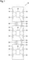
- Fig. 12 shows the basic structure of a first embodiment of an electronic irritation device of the invention.
- the irritation device 10 has several (here: three) electronic irritation signal modules 12 .
- Each of these irritation signal modules 12 contains a plurality of emitters 16, preferably at least one optical emitter 16 and at least one acoustic emitter 16.
- the optical emitters 16 contain electronic light-emitting elements such as LEDs, LED arrays, laser diodes or laser arrays, and the acoustic emitters 16 contain electronic sound generators such as piezo sound transducers.
- each of these irritation signal modules 12 contains a control device 18 which is connected to the emitters 16 for driving the emitters 16 by wire or wirelessly.
- the irritation signal modules 12 are each substantially cylindrical in shape and stacked one on top of the other.
- two of the irritation signal modules 12 are connected to one another via a mechanical or electromagnetic connecting element 32, for example, so that all irritation signal modules 12 are coupled to one another and form a unit that can be deployed as a joint projectile.
- the irritation signal modules 12 are each provided with at least one (eg mechanical and/or electrical) unlocking mechanism 34 with which one of the connecting elements 32 can be unlocked can, so that the irritation signal modules 12 can be detached from one another and thus spatially distributed.
- a mechanical expansion mechanism 36 with a spring made of metal or plastic is also provided between two irritation signal modules 12 .
- these springs are tensioned. If the connecting elements 32 are unlocked and the irritation signal modules 12 are thus detached from one another, the expansion mechanisms 35 press the irritation signal modules 12 apart and thus support and accelerate their spatial distribution.
- FIG 2 shows a more detailed construction of an irritation signal module 12 of FIG 1 .
- the components of the irritation signal module 12 are arranged in/on a module housing 14 .
- the optical/acoustic emitters 16 are positioned on the cylinder circumference of the module housing 14, for example. They are actuated by the control device 18, preferably via an interposed driver 20, in order in particular to adjust the amplitudes, frequencies, phases and signal patterns of the emitted optical/acoustic irritation pulses.
- the control device 18 is also connected to an activation switch 22 and/or an arming mechanism 23, which can be actuated, for example, before the irritation device is ejected.
- the control device 18 preferably contains a timer 24.
- the irritation signal module 12 also has a (e.g. electromagnetic or acoustic or optical) distance sensor 25 for detecting a distance between the irritation signal module 12 and an object, a position sensor 26 for detecting a position of the irritation signal module 12 (e.g by means of a GPS or GNSS system) and/or an acceleration sensor 27 for detecting a throw or an impact of the irritation signal module 12 .
- the irritation signal module 12 optionally also contains a communication device 28.
- the sensors 25, 26, 27 and the communication device 28 are also connected to the control device 18.
- the activation switch 22, the arming mechanism 23, the sensors 25, 26, 27 and the communication device 28 serve as an activation mechanism for activating the control device 18 so that it activates the unlocking mechanism directly upon activation or—with the aid of the timer 24—a predetermined time after activation 34 is actuated to unlock the connecting element 32 in order to release the irritation signal modules 12 from one another.
- irritation signal modules 12 can wait a predetermined period of time after actuation of activation switch 22 or arming mechanism 23, when the object distance detected by distance sensor 25 falls below a predetermined limit value, when irritation device 10 reaches a predetermined position, a predetermined period of time after a release or an impact of the irritation device 10 can be detached from each other.
- the object distance detected by the distance sensor 25 can also be used by the control device 18 to adapt the optical or acoustic irritation signals emitted by the emitters 16 to the object distance.
- the brightness of light pulses can be adjusted to the object distance.
- the communication device 28 can be used to receive an activation signal from a remote control.
- the communication device 28 can be used for communication between the control devices 18 of the irritation signal modules 12 of the irritation device 10 .
- an activation that takes place on an irritation signal module 12 e.g. via an actuation of the arming mechanism 23
- the irritation signals of the emitters 16 of the various irritation signal modules 12 can also be matched to one another.
- the light pulses or sound pulses can be emitted synchronously or in a well-defined pattern.
- the irritation signal module 12 is preferably also equipped with an energy store 30, preferably a rechargeable energy store, for supplying energy to the electronic components of the irritation signal module 12.
- the irritation signal module 12 is optionally also provided with a self-destruct device 48 .
- the self-destruct device 48 can be activated by remote control via the communication device 28 in order to destroy the irritation signal module 12, in particular its control device 18 .
- Fig. 12 shows the basic structure of a second embodiment of an electronic irritation device of the invention. Identical or corresponding components are given the same reference numbers as in 1 Mistake.
- essentially cylindrical irritation signal modules 12 are accommodated in an essentially spherical or cylindrical housing 38 .
- the irritation signal modules 12 are coupled to one another and a unit serving as a projectile is formed.
- the housing 38 is composed of several housing segments 40 in the form of housing shells.
- the housing segments 40 are connected to one another by mechanical or electromagnetic connecting elements 42, for example.
- Mechanical or electrical unlocking mechanisms 44 are also provided in the area of the connecting elements 42, with which the connecting elements 42 can be unlocked and the housing segments 40 can be detached from one another so that the housing 38 opens and the irritation signal module 12 is released.
- the irritation device 10 optionally contains an expansion mechanism 46, for example in the form of a gas cartridge.
- the controller 18 of one of the irritation signal modules 12 is used as the master controller.
- This master controller detects activation by an activation mechanism and then controls the unlocking mechanisms 44 to unlock the connecting elements 42 .
- the activation mechanism can be part of the irritation signal module 12 with the master controller 18 (see above 2 ) or provided separately in / on the housing 38 of the irritation device 10 be. Also, instead of a master control of the control devices 18 of the irritation signal modules 12, a separate control can be provided in the irritation device 10.
- the irritation signal modules 12 of the irritation device 10 of 3 according to 2 be designed.
- a housing 38 which can be destroyed by a mechanism in order to release the irritation signal modules 12 can be used as an embodiment variant of the second exemplary embodiment.
- a housing 38 can be used as a further variant of the second exemplary embodiment, which shatters when it is struck and thus releases the irritation signal module 12 .
- the housing 38 is formed of a brittle material, for example.
Landscapes
- Engineering & Computer Science (AREA)
- General Engineering & Computer Science (AREA)
- Radar, Positioning & Navigation (AREA)
- Remote Sensing (AREA)
- Physics & Mathematics (AREA)
- Acoustics & Sound (AREA)
- Optics & Photonics (AREA)
- Chemical & Material Sciences (AREA)
- Combustion & Propulsion (AREA)
- Toys (AREA)
- Lock And Its Accessories (AREA)
- Burglar Alarm Systems (AREA)
Claims (12)
- Dispositif irritant électronique (10), présentant :plusieurs modules de signal d'irritation (12) qui présentent respectivement au moins un émetteur (16) pour émettre des signaux d'irritation optiques ou acoustiques ;un équipement de liaison (32 ; 38 ; 38, 40, 42) pour coupler les plusieurs modules de signal d'irritation (12) les uns avec les autres ;caractérisé en ce que le dispositif d'irritation électronique (10) présente un équipement de déverrouillage (34 ; 38 ; 44) pour le déverrouillage automatique de l'équipement de liaison (32 ; 38 ; 38, 40, 42) afin de découpler les plusieurs modules de signal d'irritation (12) les uns des autres.
- Dispositif d'irritation selon la revendication 1, qui présente en outre au moins un mécanisme d'activation (22, 25, 26, 27, 28) pour activer le détachement des plusieurs modules de signal d'irritation (12) les uns des autres et au moins un équipement de commande (18) pour actionner l'équipement de déverrouillage (34 ; 44) directement au moment d'une activation par ledit au moins un mécanisme d'activation ou après un délai prédéterminé après celle-ci.
- Dispositif d'irritation selon la revendication 2, dans lequel ledit au moins un mécanisme d'activation (22, 25, 26, 27, 28) présente un commutateur d'activation (22), un mécanisme d'armement (23), un capteur (25, 26, 27) pour détecter une situation de fonctionnement et/ou un équipement de communication (28) pour recevoir une instruction d'activation.
- Dispositif d'irritation selon l'une quelconque des revendications précédentes, qui présente en outre un mécanisme d'expansion (36 ; 46) pour disperser les modules de signal d'irritation (12) après un déverrouillage de l'équipement de liaison (32 ; 38 ; 38, 40, 42).
- Dispositif d'irritation selon l'une quelconque des revendications 1 à 4, dans lequell'équipement de liaison présente des éléments de liaison (32) par lesquels les plusieurs modules de signal d'irritation (12) sont reliés les uns aux autres, etl'équipement de déverrouillage présente des mécanismes de déverrouillage (34) pour déverrouiller les éléments de liaison (32) et détacher les modules de signal d'irritation (12) les uns des autres.
- Dispositif d'irritation selon l'une quelconque des revendications 1 à 4, dans lequell'équipement de liaison présente un boîtier (38) dans lequel sont reçus les plusieurs modules de signal d'irritation (12) et qui est composé de plusieurs segments de boîtier (40) qui sont reliés les uns aux autres par des éléments de liaison (42), etl'équipement de déverrouillage présente des mécanismes de déverrouillage (44) pour déverrouiller les éléments de liaison (42) et détacher les segments de boîtier (40) les uns des autres.
- Dispositif d'irritation selon l'une quelconque des revendications 1 à 4, dans lequell'équipement de liaison présente un boîtier (38) dans lequel sont reçus les plusieurs modules de signal d'irritation (12), etl'équipement de déverrouillage présente un mécanisme pour la destruction du boîtier (38).
- Dispositif d'irritation selon les revendications 1 à 4, dans lequel l'équipement de liaison présente un boîtier (38) qui est fragile et qui se casse en cas d'impact du dispositif d'irritation (10) et libère les plusieurs modules de signal d'irritation (12).
- Dispositif d'irritation selon l'une quelconque des revendications précédentes, dans lequel les plusieurs modules de signal d'irritation (12) présentent respectivement un équipement de commande (18) pour piloter ledit au moins un émetteur (16) et un équipement de communication (28) relié à l'équipement de commande (18) de sorte que les équipements de commande (18) des modules de signal d'irritation (12) peuvent communiquer entre eux et/ou avec une commande de niveau supérieur afin de synchroniser le pilotage des émetteurs (16) des différents modules de signal d'irritation (12).
- Dispositif d'irritation selon l'une quelconque des revendications précédentes, dans lequel au moins l'un des plusieurs modules de signal d'irritation (12) présente un équipement de commande (18) pour piloter ledit au moins un émetteur (16) et un capteur de distance (25) relié à l'équipement de commande (18) pour détecter une distance entre le module de signal d'irritation (12) et un objet, l'équipement de commande (18) étant configuré pour piloter ledit au moins un émetteur (16) du module de signal d'irritation (12) en fonction de la distance détectée par rapport à un objet.
- Dispositif d'irritation selon l'une quelconque des revendications précédentes, dans lequel au moins l'un des plusieurs modules de signal d'irritation (12) présente un accumulateur d'énergie intégré (30).
- Dispositif d'irritation selon l'une quelconque des revendications précédentes, dans lequel les plusieurs modules de signal d'irritation (12) présentent respectivement un équipement d'autodestruction (48) pour l'autodestruction du module de signal d'irritation.
Applications Claiming Priority (2)
| Application Number | Priority Date | Filing Date | Title |
|---|---|---|---|
| DE102018008647.0A DE102018008647A1 (de) | 2018-11-02 | 2018-11-02 | Elektronische Irritationsvorrichtung |
| PCT/EP2019/079436 WO2020089184A1 (fr) | 2018-11-02 | 2019-10-28 | Dispositif irritant électronique |
Publications (3)
| Publication Number | Publication Date |
|---|---|
| EP3874222A1 EP3874222A1 (fr) | 2021-09-08 |
| EP3874222B1 true EP3874222B1 (fr) | 2023-06-07 |
| EP3874222C0 EP3874222C0 (fr) | 2023-06-07 |
Family
ID=68387337
Family Applications (1)
| Application Number | Title | Priority Date | Filing Date |
|---|---|---|---|
| EP19795204.7A Active EP3874222B1 (fr) | 2018-11-02 | 2019-10-28 | Dispositif irritant électronique |
Country Status (4)
| Country | Link |
|---|---|
| US (1) | US11859951B2 (fr) |
| EP (1) | EP3874222B1 (fr) |
| DE (1) | DE102018008647A1 (fr) |
| WO (1) | WO2020089184A1 (fr) |
Families Citing this family (5)
| Publication number | Priority date | Publication date | Assignee | Title |
|---|---|---|---|---|
| DE102018008647A1 (de) * | 2018-11-02 | 2020-05-07 | Diehl Stiftung & Co. Kg | Elektronische Irritationsvorrichtung |
| DE102018128485B4 (de) * | 2018-11-14 | 2022-05-05 | Rheinmetall Waffe Munition Gmbh | Elektronische Zündereinheit für einen Irritationskörper und Irritationskörper |
| DE102019102722A1 (de) * | 2019-02-04 | 2020-08-06 | Ruag Ammotec Gmbh | Geschoss mit einem Kaliber von weniger als 13 mm und System zum Nachverfolgen eines Geschosses |
| US20230106685A1 (en) * | 2019-06-29 | 2023-04-06 | University Of Miami | Lighting system |
| US12025410B2 (en) * | 2021-05-01 | 2024-07-02 | Scott Douglas Southworth | Non-lethal disruption device |
Family Cites Families (16)
| Publication number | Priority date | Publication date | Assignee | Title |
|---|---|---|---|---|
| DE2842797C2 (de) * | 1978-09-30 | 1986-01-23 | Nico-Pyrotechnik Hans-Jürgen Diederichs KG, 2077 Trittau | Wurfkörper |
| US6767108B1 (en) * | 2002-12-10 | 2004-07-27 | The United States Of America As Represented By The Secretary Of The Navy | Non-lethal flash grenade |
| US8113689B2 (en) * | 2007-03-08 | 2012-02-14 | Nanohmics, Inc. | Non-lethal projectile for disorienting adversaries |
| US8726810B2 (en) * | 2012-03-19 | 2014-05-20 | Combined Systems, Inc. | Grenade having safety lever with integrated firing pin retaining clip |
| WO2014066917A1 (fr) * | 2012-10-25 | 2014-05-01 | Lester Ian | Dispositif de sécurité |
| WO2014121480A1 (fr) * | 2013-02-07 | 2014-08-14 | Ma Kali | Grenade infrarouge pour jeu de confrontation de tir laser et système de jeu de confrontation de tir laser |
| US8899156B1 (en) * | 2013-12-17 | 2014-12-02 | STARJET Technologies Co., Ltd | Stun grenade with time delay |
| EP3209927A4 (fr) * | 2014-10-21 | 2018-05-09 | Night Angle Products, LLC | Dispositifs d'éclairage à côtés multiples déployables et procédés d'utilisation associés |
| EP3023730A1 (fr) | 2014-11-20 | 2016-05-25 | Diehl BGT Defence GmbH & Co. Kg | Grenade eblouissante |
| EP3023731A1 (fr) | 2014-11-20 | 2016-05-25 | Diehl BGT Defence GmbH & Co. Kg | Dispositif d'irritation destine a envoyer des signaux d'irritation optiques ou acoustiques sous forme d'impulsion lumineuse et acoustique |
| GB2539421B (en) * | 2015-06-16 | 2021-06-09 | Amtec Less Lethal Systems Inc | Firing mechanism for a grenade, a grenade and a method of operating a grenade |
| US20170116874A1 (en) * | 2015-10-27 | 2017-04-27 | Tdpb Holdings, Llc | Tactical skills development, assessment and reporting system |
| GB2555865A (en) * | 2016-11-15 | 2018-05-16 | Bae Systems Plc | Flash grenade and acoustic module therefor |
| DE102018008647A1 (de) * | 2018-11-02 | 2020-05-07 | Diehl Stiftung & Co. Kg | Elektronische Irritationsvorrichtung |
| DE102018008663B4 (de) * | 2018-11-02 | 2023-09-28 | Diehl Stiftung & Co. Kg | Elektronischer Blendkörper |
| DE102018008662B4 (de) * | 2018-11-02 | 2024-09-26 | Diehl Stiftung & Co. Kg | Verfahren zum Betreiben eines elektronischen Blendkörpers und elektronischer Blendkörper |
-
2018
- 2018-11-02 DE DE102018008647.0A patent/DE102018008647A1/de not_active Withdrawn
-
2019
- 2019-10-28 EP EP19795204.7A patent/EP3874222B1/fr active Active
- 2019-10-28 WO PCT/EP2019/079436 patent/WO2020089184A1/fr not_active Ceased
-
2021
- 2021-05-03 US US17/246,899 patent/US11859951B2/en active Active
Also Published As
| Publication number | Publication date |
|---|---|
| DE102018008647A1 (de) | 2020-05-07 |
| EP3874222A1 (fr) | 2021-09-08 |
| US20210254937A1 (en) | 2021-08-19 |
| WO2020089184A1 (fr) | 2020-05-07 |
| US11859951B2 (en) | 2024-01-02 |
| EP3874222C0 (fr) | 2023-06-07 |
Similar Documents
| Publication | Publication Date | Title |
|---|---|---|
| EP3874222B1 (fr) | Dispositif irritant électronique | |
| EP1832200B1 (fr) | Dispositif et unité de sécurité destinés à la conservation d'une arme de tir | |
| EP3023731A1 (fr) | Dispositif d'irritation destine a envoyer des signaux d'irritation optiques ou acoustiques sous forme d'impulsion lumineuse et acoustique | |
| DE102004025718B4 (de) | Schießanlagensicherung | |
| DE69021174T2 (de) | Einrichtung zur Zündung von Explosivkörpern. | |
| EP3874225B1 (fr) | Corps d'éblouissement électronique | |
| EP2610821B1 (fr) | Procédé de détection d'un élément d'identification pourvu d'un transpondeur optique | |
| DE19619135C2 (de) | Unbemanntes gepanzertes Minenräumfahrzeug | |
| EP2071270B1 (fr) | Dispositif d'allumage en nutation | |
| EP3023730A1 (fr) | Grenade eblouissante | |
| DE19751933A1 (de) | Treibladungshülse | |
| EP3109586A1 (fr) | Projectile destine a intercepter un petit drone | |
| EP3881027B1 (fr) | Unité d'allumage électronique pour une grenade incapacitante et grenade incapacitante | |
| DE102012101037B3 (de) | Wurfanlage, Fahrzeug und Verfahren zum Abschuss eines Wurfkörpers | |
| DE202012002149U1 (de) | Vorrichtung zum Irritieren von Personen oder Personenansammlungen | |
| DE69902704T2 (de) | Mine, insbesondere zur Panzer- oder Fahrzeugbekämpfung, mit Mitteln zur Bestätigung des Vorhandenseins eines Ziels | |
| EP0492299A2 (fr) | Mine comportant un dispositif de pose pour un fil senseur | |
| EP0520176B1 (fr) | Dispositif de déclenchement notamment pour des signaux pyrotechniques | |
| DE19960392A1 (de) | Feuerwerksanlage | |
| DE3936807C1 (en) | Anti-tank mine detonator - with electro-mechanical timer allowing external timing adjustment | |
| DE19626074C1 (de) | Zündsystem zum verzögerten Zünden einer Munition | |
| EP3410058B1 (fr) | Système actif comprenant au moins une charge et au moins une unité de déclenchement | |
| DE2639883A1 (de) | Wurfgranate | |
| EP3183531B1 (fr) | Dispositif de projection | |
| AT393561B (de) | Sicherungsvorrichtung fuer landminen |
Legal Events
| Date | Code | Title | Description |
|---|---|---|---|
| STAA | Information on the status of an ep patent application or granted ep patent |
Free format text: STATUS: UNKNOWN |
|
| STAA | Information on the status of an ep patent application or granted ep patent |
Free format text: STATUS: THE INTERNATIONAL PUBLICATION HAS BEEN MADE |
|
| PUAI | Public reference made under article 153(3) epc to a published international application that has entered the european phase |
Free format text: ORIGINAL CODE: 0009012 |
|
| STAA | Information on the status of an ep patent application or granted ep patent |
Free format text: STATUS: REQUEST FOR EXAMINATION WAS MADE |
|
| 17P | Request for examination filed |
Effective date: 20210429 |
|
| AK | Designated contracting states |
Kind code of ref document: A1 Designated state(s): AL AT BE BG CH CY CZ DE DK EE ES FI FR GB GR HR HU IE IS IT LI LT LU LV MC MK MT NL NO PL PT RO RS SE SI SK SM TR |
|
| DAV | Request for validation of the european patent (deleted) | ||
| DAX | Request for extension of the european patent (deleted) | ||
| GRAP | Despatch of communication of intention to grant a patent |
Free format text: ORIGINAL CODE: EPIDOSNIGR1 |
|
| STAA | Information on the status of an ep patent application or granted ep patent |
Free format text: STATUS: GRANT OF PATENT IS INTENDED |
|
| INTG | Intention to grant announced |
Effective date: 20220601 |
|
| GRAS | Grant fee paid |
Free format text: ORIGINAL CODE: EPIDOSNIGR3 |
|
| GRAA | (expected) grant |
Free format text: ORIGINAL CODE: 0009210 |
|
| STAA | Information on the status of an ep patent application or granted ep patent |
Free format text: STATUS: THE PATENT HAS BEEN GRANTED |
|
| AK | Designated contracting states |
Kind code of ref document: B1 Designated state(s): AL AT BE BG CH CY CZ DE DK EE ES FI FR GB GR HR HU IE IS IT LI LT LU LV MC MK MT NL NO PL PT RO RS SE SI SK SM TR |
|
| REG | Reference to a national code |
Ref country code: GB Ref legal event code: FG4D Free format text: NOT ENGLISH |
|
| REG | Reference to a national code |
Ref country code: CH Ref legal event code: EP Ref country code: AT Ref legal event code: REF Ref document number: 1576298 Country of ref document: AT Kind code of ref document: T Effective date: 20230615 |
|
| REG | Reference to a national code |
Ref country code: DE Ref legal event code: R096 Ref document number: 502019008120 Country of ref document: DE |
|
| U01 | Request for unitary effect filed |
Effective date: 20230607 |
|
| U07 | Unitary effect registered |
Designated state(s): AT BE BG DE DK EE FI FR IT LT LU LV MT NL PT SE SI Effective date: 20230612 |
|
| REG | Reference to a national code |
Ref country code: LT Ref legal event code: MG9D |
|
| PG25 | Lapsed in a contracting state [announced via postgrant information from national office to epo] |
Ref country code: NO Free format text: LAPSE BECAUSE OF FAILURE TO SUBMIT A TRANSLATION OF THE DESCRIPTION OR TO PAY THE FEE WITHIN THE PRESCRIBED TIME-LIMIT Effective date: 20230907 Ref country code: ES Free format text: LAPSE BECAUSE OF FAILURE TO SUBMIT A TRANSLATION OF THE DESCRIPTION OR TO PAY THE FEE WITHIN THE PRESCRIBED TIME-LIMIT Effective date: 20230607 |
|
| U20 | Renewal fee for the european patent with unitary effect paid |
Year of fee payment: 5 Effective date: 20231018 |
|
| PG25 | Lapsed in a contracting state [announced via postgrant information from national office to epo] |
Ref country code: RS Free format text: LAPSE BECAUSE OF FAILURE TO SUBMIT A TRANSLATION OF THE DESCRIPTION OR TO PAY THE FEE WITHIN THE PRESCRIBED TIME-LIMIT Effective date: 20230607 Ref country code: HR Free format text: LAPSE BECAUSE OF FAILURE TO SUBMIT A TRANSLATION OF THE DESCRIPTION OR TO PAY THE FEE WITHIN THE PRESCRIBED TIME-LIMIT Effective date: 20230607 Ref country code: GR Free format text: LAPSE BECAUSE OF FAILURE TO SUBMIT A TRANSLATION OF THE DESCRIPTION OR TO PAY THE FEE WITHIN THE PRESCRIBED TIME-LIMIT Effective date: 20230908 |
|
| PG25 | Lapsed in a contracting state [announced via postgrant information from national office to epo] |
Ref country code: SK Free format text: LAPSE BECAUSE OF FAILURE TO SUBMIT A TRANSLATION OF THE DESCRIPTION OR TO PAY THE FEE WITHIN THE PRESCRIBED TIME-LIMIT Effective date: 20230607 |
|
| PG25 | Lapsed in a contracting state [announced via postgrant information from national office to epo] |
Ref country code: IS Free format text: LAPSE BECAUSE OF FAILURE TO SUBMIT A TRANSLATION OF THE DESCRIPTION OR TO PAY THE FEE WITHIN THE PRESCRIBED TIME-LIMIT Effective date: 20231007 |
|
| PG25 | Lapsed in a contracting state [announced via postgrant information from national office to epo] |
Ref country code: SM Free format text: LAPSE BECAUSE OF FAILURE TO SUBMIT A TRANSLATION OF THE DESCRIPTION OR TO PAY THE FEE WITHIN THE PRESCRIBED TIME-LIMIT Effective date: 20230607 Ref country code: SK Free format text: LAPSE BECAUSE OF FAILURE TO SUBMIT A TRANSLATION OF THE DESCRIPTION OR TO PAY THE FEE WITHIN THE PRESCRIBED TIME-LIMIT Effective date: 20230607 Ref country code: RO Free format text: LAPSE BECAUSE OF FAILURE TO SUBMIT A TRANSLATION OF THE DESCRIPTION OR TO PAY THE FEE WITHIN THE PRESCRIBED TIME-LIMIT Effective date: 20230607 Ref country code: IS Free format text: LAPSE BECAUSE OF FAILURE TO SUBMIT A TRANSLATION OF THE DESCRIPTION OR TO PAY THE FEE WITHIN THE PRESCRIBED TIME-LIMIT Effective date: 20231007 Ref country code: CZ Free format text: LAPSE BECAUSE OF FAILURE TO SUBMIT A TRANSLATION OF THE DESCRIPTION OR TO PAY THE FEE WITHIN THE PRESCRIBED TIME-LIMIT Effective date: 20230607 |
|
| PG25 | Lapsed in a contracting state [announced via postgrant information from national office to epo] |
Ref country code: PL Free format text: LAPSE BECAUSE OF FAILURE TO SUBMIT A TRANSLATION OF THE DESCRIPTION OR TO PAY THE FEE WITHIN THE PRESCRIBED TIME-LIMIT Effective date: 20230607 |
|
| REG | Reference to a national code |
Ref country code: DE Ref legal event code: R097 Ref document number: 502019008120 Country of ref document: DE |
|
| PLBE | No opposition filed within time limit |
Free format text: ORIGINAL CODE: 0009261 |
|
| STAA | Information on the status of an ep patent application or granted ep patent |
Free format text: STATUS: NO OPPOSITION FILED WITHIN TIME LIMIT |
|
| 26N | No opposition filed |
Effective date: 20240308 |
|
| PG25 | Lapsed in a contracting state [announced via postgrant information from national office to epo] |
Ref country code: MC Free format text: LAPSE BECAUSE OF FAILURE TO SUBMIT A TRANSLATION OF THE DESCRIPTION OR TO PAY THE FEE WITHIN THE PRESCRIBED TIME-LIMIT Effective date: 20230607 |
|
| REG | Reference to a national code |
Ref country code: CH Ref legal event code: PL |
|
| PG25 | Lapsed in a contracting state [announced via postgrant information from national office to epo] |
Ref country code: CH Free format text: LAPSE BECAUSE OF NON-PAYMENT OF DUE FEES Effective date: 20231031 |
|
| PG25 | Lapsed in a contracting state [announced via postgrant information from national office to epo] |
Ref country code: CH Free format text: LAPSE BECAUSE OF NON-PAYMENT OF DUE FEES Effective date: 20231031 |
|
| PG25 | Lapsed in a contracting state [announced via postgrant information from national office to epo] |
Ref country code: IE Free format text: LAPSE BECAUSE OF NON-PAYMENT OF DUE FEES Effective date: 20231028 |
|
| PG25 | Lapsed in a contracting state [announced via postgrant information from national office to epo] |
Ref country code: IE Free format text: LAPSE BECAUSE OF NON-PAYMENT OF DUE FEES Effective date: 20231028 |
|
| U20 | Renewal fee for the european patent with unitary effect paid |
Year of fee payment: 6 Effective date: 20241003 |
|
| PG25 | Lapsed in a contracting state [announced via postgrant information from national office to epo] |
Ref country code: CY Free format text: LAPSE BECAUSE OF FAILURE TO SUBMIT A TRANSLATION OF THE DESCRIPTION OR TO PAY THE FEE WITHIN THE PRESCRIBED TIME-LIMIT; INVALID AB INITIO Effective date: 20191028 |
|
| PG25 | Lapsed in a contracting state [announced via postgrant information from national office to epo] |
Ref country code: HU Free format text: LAPSE BECAUSE OF FAILURE TO SUBMIT A TRANSLATION OF THE DESCRIPTION OR TO PAY THE FEE WITHIN THE PRESCRIBED TIME-LIMIT; INVALID AB INITIO Effective date: 20191028 |
|
| U20 | Renewal fee for the european patent with unitary effect paid |
Year of fee payment: 7 Effective date: 20251020 |
|
| PG25 | Lapsed in a contracting state [announced via postgrant information from national office to epo] |
Ref country code: TR Free format text: LAPSE BECAUSE OF FAILURE TO SUBMIT A TRANSLATION OF THE DESCRIPTION OR TO PAY THE FEE WITHIN THE PRESCRIBED TIME-LIMIT Effective date: 20230607 |
|
| PGFP | Annual fee paid to national office [announced via postgrant information from national office to epo] |
Ref country code: GB Payment date: 20251022 Year of fee payment: 7 |