EP3875143B1 - System zur energieversorgung einer implantierbaren medizinischen vorrichtung - Google Patents
System zur energieversorgung einer implantierbaren medizinischen vorrichtung Download PDFInfo
- Publication number
- EP3875143B1 EP3875143B1 EP20215955.4A EP20215955A EP3875143B1 EP 3875143 B1 EP3875143 B1 EP 3875143B1 EP 20215955 A EP20215955 A EP 20215955A EP 3875143 B1 EP3875143 B1 EP 3875143B1
- Authority
- EP
- European Patent Office
- Prior art keywords
- coil
- energy
- implanted
- medical device
- patient
- Prior art date
- Legal status (The legal status is an assumption and is not a legal conclusion. Google has not performed a legal analysis and makes no representation as to the accuracy of the status listed.)
- Active
Links
Images






Classifications
-
- A—HUMAN NECESSITIES
- A61—MEDICAL OR VETERINARY SCIENCE; HYGIENE
- A61N—ELECTROTHERAPY; MAGNETOTHERAPY; RADIATION THERAPY; ULTRASOUND THERAPY
- A61N1/00—Electrotherapy; Circuits therefor
- A61N1/18—Applying electric currents by contact electrodes
- A61N1/32—Applying electric currents by contact electrodes alternating or intermittent currents
- A61N1/36—Applying electric currents by contact electrodes alternating or intermittent currents for stimulation
- A61N1/372—Arrangements in connection with the implantation of stimulators
- A61N1/378—Electrical supply
- A61N1/3787—Electrical supply from an external energy source
-
- A—HUMAN NECESSITIES
- A61—MEDICAL OR VETERINARY SCIENCE; HYGIENE
- A61N—ELECTROTHERAPY; MAGNETOTHERAPY; RADIATION THERAPY; ULTRASOUND THERAPY
- A61N1/00—Electrotherapy; Circuits therefor
- A61N1/18—Applying electric currents by contact electrodes
- A61N1/32—Applying electric currents by contact electrodes alternating or intermittent currents
- A61N1/36—Applying electric currents by contact electrodes alternating or intermittent currents for stimulation
- A61N1/372—Arrangements in connection with the implantation of stimulators
- A61N1/37211—Means for communicating with stimulators
- A61N1/37217—Means for communicating with stimulators characterised by the communication link, e.g. acoustic or tactile
- A61N1/37223—Circuits for electromagnetic coupling
-
- H—ELECTRICITY
- H02—GENERATION; CONVERSION OR DISTRIBUTION OF ELECTRIC POWER
- H02J—ELECTRIC POWER NETWORKS; CIRCUIT ARRANGEMENTS OR SYSTEMS FOR SUPPLYING OR DISTRIBUTING ELECTRIC POWER; SYSTEMS FOR STORING ELECTRIC ENERGY
- H02J50/00—Circuit arrangements or systems for wireless supply or distribution of electric power
- H02J50/10—Circuit arrangements or systems for wireless supply or distribution of electric power using inductive coupling
-
- H—ELECTRICITY
- H02—GENERATION; CONVERSION OR DISTRIBUTION OF ELECTRIC POWER
- H02J—ELECTRIC POWER NETWORKS; CIRCUIT ARRANGEMENTS OR SYSTEMS FOR SUPPLYING OR DISTRIBUTING ELECTRIC POWER; SYSTEMS FOR STORING ELECTRIC ENERGY
- H02J7/00—Circuit arrangements for charging or discharging batteries or for supplying loads from batteries
- H02J7/40—Circuit arrangements for charging or discharging batteries or for supplying loads from batteries characterised by the exchange of charge or discharge related data
- H02J7/42—Circuit arrangements for charging or discharging batteries or for supplying loads from batteries characterised by the exchange of charge or discharge related data with electronic devices having internal batteries, e.g. mobile phones
-
- A—HUMAN NECESSITIES
- A61—MEDICAL OR VETERINARY SCIENCE; HYGIENE
- A61N—ELECTROTHERAPY; MAGNETOTHERAPY; RADIATION THERAPY; ULTRASOUND THERAPY
- A61N1/00—Electrotherapy; Circuits therefor
- A61N1/18—Applying electric currents by contact electrodes
- A61N1/32—Applying electric currents by contact electrodes alternating or intermittent currents
- A61N1/36—Applying electric currents by contact electrodes alternating or intermittent currents for stimulation
- A61N1/372—Arrangements in connection with the implantation of stimulators
- A61N1/37211—Means for communicating with stimulators
- A61N1/37217—Means for communicating with stimulators characterised by the communication link, e.g. acoustic or tactile
- A61N1/37223—Circuits for electromagnetic coupling
- A61N1/37229—Shape or location of the implanted or external antenna
-
- H—ELECTRICITY
- H01—ELECTRIC ELEMENTS
- H01F—MAGNETS; INDUCTANCES; TRANSFORMERS; SELECTION OF MATERIALS FOR THEIR MAGNETIC PROPERTIES
- H01F38/00—Adaptations of transformers or inductances for specific applications or functions
- H01F38/14—Inductive couplings
-
- H—ELECTRICITY
- H02—GENERATION; CONVERSION OR DISTRIBUTION OF ELECTRIC POWER
- H02J—ELECTRIC POWER NETWORKS; CIRCUIT ARRANGEMENTS OR SYSTEMS FOR SUPPLYING OR DISTRIBUTING ELECTRIC POWER; SYSTEMS FOR STORING ELECTRIC ENERGY
- H02J2105/00—Networks for supplying or distributing electric power characterised by their spatial reach or by the load
- H02J2105/40—Networks for supplying or distributing electric power characterised by their spatial reach or by the load characterised by the loads connecting to the networks or being supplied by the networks
- H02J2105/46—Medical devices, medical implants or life supporting devices
Definitions
- the present invention relates to medical implants, and, more particularly, to an improved coil for supplying energy or control signals to, or information from, a medical device implanted in a human or animal patient's body.
- Medical devices are implanted in humans or animals for many reasons. Some of these devices are used to monitor one or more bodily functions. Other devices are used to stimulate or out rightly control bodily functions. Often, the medical devices will include some kind of communications circuit for receiving signals used to power and/or control the devices, or for sending outside a patient's body information about the medical device or bodily functions monitored or controlled by the device. Typically, medical devices are powered by an electric power supply, such as a battery, that provides the voltage and current needed for their operation.
- an electric power supply such as a battery
- Medical devices are often intended to be implanted in a patient's body for many years, and in some instances, for the rest of a patient's life.
- the power supplies used to power these long-term medical devices are implanted in a patient at a location that permits easy access from outside the patient's body for recharging or replacement of the power supply.
- these power supplies are recharged by energy drawn from an alternating magnetic field transmitted from outside of a patient's body to inside of the patient's body using a pair of coils.
- the pair of coils includes a first coil that is part of a transmitter that generates the alternating magnetic field and a second coil that is part of a receiver that is also implanted in a patient's body.
- the second coil implanted in a patient's body may be connected directly to a power supply or a medical device implanted in the patient.
- the second coil is often implanted subcutaneously in a patient to permit easy access to it from outside of the patient's body, there is a risk that the second coil, over time, may become intermittently inoperable, or even completely fail, because movements of the patient over time cause the secondary coil to break.
- WO2009051539 A1 shows a method and system for supplying energy to an electrically operable, medical device implanted in a patient.
- US2007/0287969 A1 shows a microinfusion device including coils or antennas disposed proximate to a ring-shaped reservoir to provide/ receive signals from an external transmitter to a dose controller to control dosing of a drug through a microcatheter.
- US 6 542 777 shows a spiral shield for a flexible high-Q implantable inductively coupled device.
- US2006/0206170 A1 shows an implantable medical apparatus having an omnidirectional antenna for receiving radio frequency signals.
- the present invention provides a medical implant according to claim 1 and a system according to claim 12 comprising said medical implant.
- Preferred embodiments are defined by the dependent claims.
- the present disclosure is directed to an improved coil for supplying energy or control signals to, or providing information from, a medical device implanted in a human or animal patient where the medical device is used to monitor one or more bodily functions or to stimulate or out rightly control one or more bodily functions.
- the coil is implanted in a patient at a location that permits easy access to the coil from outside of the patient's body.
- the coil is implanted subcutaneously in a patient at a suitable location for such easy access.
- the coil can be connected to an implanted control device which, in turn, is connected to an implanted power supply connected to an implanted medical device, or directly to the implanted medical device.
- the coil can be connected to the implanted power supply connected to the medical device, or directly to the implanted medical device.
- the implanted coil is preferably connected to an implanted control device that is a receiver which, in turn, is connected to the implanted medical device.
- the implanted coil also transmits information from the implanted medical device
- the coil is preferably connected to an implanted control device that is a transceiver which, in turn, is connected to the implanted medical device.
- the transceiver functions to receive control signals received by the coil and to provide informational signals to the coil for transmission outside of the patient's body.
- the implanted coil which performs the foregoing communications functions, is wound from a wire that is formed into a plurality of smaller diameter coils connected in series.
- the smaller diameter coils are caused to be positioned perpendicular to the longitudinal axis of the larger implanted coil.
- the wire used to form the implanted coil is a helically-shaped wire that is very resilient, and, thus, capable of handling, without the risk of breaking, even extreme movements of a patient in whom it is implanted.
- coil refers to an arrangement having at least one winding.
- the internal area of the coil as seen from one end thereof.
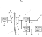
- Fig. 1 is a schematic diagram of a system 1 using the improved coil 32 of the present invention to supply energy or control signals to, or information from, a medical device 10 implanted in a human or animal patient's body.
- Fig. 1 shows the basic parts of the system 1. All parts placed to the left of the patient's skin 4 are located outside of the patient's body and all parts placed to the right of the skin 4 are implanted in the patient's body.
- the system 1 includes a pair of coils 22 and 32 that function as inductively coupled electrical conductors forming a transformer like circuit for the purpose of transferring alternating electrical energy signals into and out of a patient's body that supply energy or control signals to, or information from, the medical device 10 implanted in the patient's body 6.
- a transformer is an electrical device that transfers electrical energy from one circuit to another circuit through inductively coupled electrical conductors formed into coils.
- An alternating current in a first winding or circuit of the transformer, often called the primary circuit creates an alternating magnetic field, which induces an alternating voltage in a second winding or circuit of the transformer, often called the secondary circuit.
- An electric charge then flows in the secondary winding or circuit to a load circuit connected to the secondary circuit, so as to transfer energy from the primary circuit through the secondary circuit to the load circuit connected into secondary circuit.
- the system 1 includes an external control unit 20 located outside of the patient's body.
- the external control unit 20 is comprised of a generator for generating an alternating electromagnetic signal, a modulator circuit and a power amplifier.
- the external control unit 20 may include a microprocessor for generating control signals to be sent to the implanted medical device 10.
- the microprocessor is capable of switching the generator on and off and of controlling the modulator circuit to modulate signals generated by the generator to send control information to the implanted medical device 10 via the power amplifier and a transmitting coil 22 connected to the power amplifier in the external control unit 20.
- the external control unit 20 is a transceiver that functions to both transmit control signals to the implanted medical device 10 and receive information signals from the implanted medical device 10
- the external control unit 20 also includes a demodulator that is also connected to external coil 22, which receives the information sent from the implanted medical device 10.
- the demodulator demodulates information signals received by the external coil 22 so as to strip out the information sent from the implanted medical device 10.
- information will relate to bodily functions being monitored by the implanted medical device or the results of bodily functions controlled by the implanted medical device.
- Implanted in the patient's body is an implanted control unit 30, which is connected to the implanted coil 32.
- the implanted control unit 30 will include a rectifier circuit for converting alternating signals received by the coil 32 into a direct current signal that is suitable for either powering the operation of the implanted medical device 10 or charging an implanted rechargeable energizer unit 34 that powers the operation of the implanted medical device 10.
- the implanted control unit 30 will be further comprised of a demodulator and a microprocessor.
- the demodulator demodulates signals sent from the external control unit 20.
- the microprocessor receives the demodulated signal and sends control signals via a control line 33 to the implanted medical device to control its operation.
- the implanted control unit 30 is a transceiver that functions to both receive control signals from the external control unit 20 and transmit information from the implanted medical device 10
- the implanted control unit 30 will also include a generator for generating an alternating electromagnetic signal, a modulator circuit for modulating the generated alternating electromagnetic signal and a power amplifier connected to the implanted coil 32.
- the microprocessor is capable of switching the generator on and off and of controlling the modulation circuit to modulate the signals generated by the generator to send information from the implanted medical device 10 via the power amplifier and implanted coil 32 connected to the power amplifier to the external control unit 20.
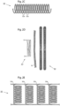
- Fig. 2A is a schematic sectional diagram of the implanted coil 32 of the present invention implanted inside a patient's body and another coil 22 inductively coupled to the implanted coil 32 that is located outside of the patient's body and separated by the patient's skin 4.
- Fig. 2B is a plan view of the implanted coil 32 as seen in the direction from outside the patient.
- the coil comprises one single large winding, the ends of which are connected to the medical implant.
- the implanted coil 32 is formed from a wire that is formed into a plurality of smaller diameter coils or windings 32a that are connected in series.
- the wire is wound to form the implanted coil 32, the smaller diameter coils or windings 32a are caused to be positioned substantially perpendicular to the longitudinal axis of implanted coil 32.
- the wire is a helically-shaped wire that is very resilient, and, thus, capable of handling even extreme movements of a patient 2 in whom it is implanted without the risk of breaking.
- Fig. 2D is a diagram similar to that of Fig. 2A but showing an implanted coil 32 comprising a plurality of large windings, in the shown embodiment two large windings, each of the large windings being made up of a plurality of small diameter coils or windings.
- Fig. 2E is a detailed view of another embodiment of the coil shown in Fig. 2B , wherein the implanted coil 32 comprises a plurality of coils connected in parallel.
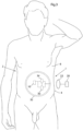
- Fig. 3 is a schematic diagram showing the implanted coil 32 of Figs. 2A-2D and the system 1 of Fig. 1 implanted in the body 6 of a human patient 2.
- the implanted coil 32 is implanted in the body 6 of patient 2 at a location that permits easy access to the coil 32 from outside of the patient's body 6.
- the coil 32 is implanted subcutaneously in the skin 4 of the patient 2 at a location for such easy access.
- the implanted control unit 30 and the rechargeable energizer unit 34 are also located at an easy access location within the body 6 of the patient 2 and then connected by one or more wires to the implanted medical device 10.
- the implanted coil 32 can take an irregular shape, adapting to the patient's body. Therefore, the implanted coil 32 can be made very large, preferably much larger than the external coil 22, and covering a large portion of the patient. This could allow for charging for example when the patient is in bed if an external coil 22 is provided in the bed structure.
- the implanted coil can be implanted either in the stomach area or the back area of the patient.
- Figs. 1 , 2A -2D and 3 are not intended to depict a particular orientation of the external coil 22 and/or the implanted coil 32 with respect to a patient with whom these devices are used. Rather, it should be noted that either or both of these devices can be oriented horizontally, vertically or otherwise with respect to a patient to accommodate the needs of a particular application in which these devices are used.
- the coil winding itself could be done any one of many different ways. Preferably, the coil winding is compact with the windings concentrated in a small transversal area. A core could also be used with the coil, but it is not required. If such a coil were to be implanted in a patient with a substantially horizontal orientation vis-à-vis the substantially vertical orientation of the patient, when standing, the coil would preferably be very low in subcutaneous height, thereby avoiding protruding material under the skin.
- Fig. 4 shows a schematic view of an exemplary medical system 1.
- the medical system 1 comprises parts intended for implantation in a patient as well as external parts intended to be used outside of the body of the patient in whom the internal parts are implanted.
- Fig. 4 shows the skin of a patient symbolically with a line "4", in order to show how the system is divided into external and internal parts.
- the external parts comprise an external energy source 11 equipped with a primary external coil 22 for transmitting energy wirelessly by means of induction to an internal energy receiver 31.
- a control unit 20 for controlling, inter alia, the external energy source 20 and its function.
- the internal parts of the system 1 comprise a medical device 10, the internal energy receiver 31 and an internal control unit 30.
- the medical device 10 is electrically powered, and as indicated by the name, the purpose of the internal energy receiver 31 is to receive energy and to supply that energy to the medical device 10.
- the energy which the energy receiver 31 receives for the medical device is received wirelessly, by means of induction, for which reason the energy receiver is equipped with a secondary implanted coil 32 for receiving such energy.
- a purpose of the internal control unit 30 is to control the internal parts.
- the internal control unit 30 is arranged to wirelessly transmit feedback information regarding, for example, the transfer of energy to the internal energy receiver 31, and as indicated in Fig. 4 , the feedback information is based on or relates to a first and a second parameter, P1, P2.
- the invention is applicable to a large number of implantable medical devices, for which reason the medical device is only referred to by the generic term" medical device".
- implantable electrically powered medical devices in which the present invention can be applied are devices which aid patients who suffer from urinary dysfunction, intestinal dysfunction, infertility, impotence, vascular and heart related diseases, reflux disease, obesity etc.
- the invention can also be used to assist patients with food passageway correlated devices, implanted drug delivery, drainage, etc.
- a purpose of the present disclosure is to enable a more rapid adjustment of the energy which is transferred to the implanted medical device 10, so that the energy which is transferred better corresponds to the needs of the medical device 10.
- the system 1 is arranged to determine the feedback information based on or relating to the first and second parameters P1, P2.
- the system 1 is arranged to determine a balance between the amount of energy received in the energy receiver and the amount of energy used by the medical device, and to determine the first parameter P1 being based on this energy balance over a certain amount of time.
- the energy balance can either be specified as the balance between the total amount of energy received in the energy receiver and the amount of energy used by the medical device or as the balance between the rate of energy received in the energy receiver and the rate of energy used by the medical device.
- the amount of time over which the balance is determined is a design parameter which is adapted to the specific needs of each system and application, and may thus vary, but is suitably in the range of 50-200 ms, although the disclosure covers any range of time.
- the amount of time over which the balance is determined is suitably chosen to coincide with the feedback information, which is thus also suitably transmitted at intervals of 50-200 ms, or more often or more seldom.
- the second parameter, P2 is based on information which relates to a coupling factor between the external coil 22 and the implanted coil 32.
- the intervals of time at which this coupling factor is determined is a design parameter which is adapted to the specific needs of each system and application, and may thus vary.
- the coupling factor can also be used as a calibration parameter which is determined much more rarely than the energy balance or it may also be simultaneously controlled.
- the second parameter P2 will normally not change since it is related to the coupling factor, if the external coil is kept stationary.
- the system 1 is adapted to take into account at least both the first P1 and the second P2 parameter in order to determine the amount of energy which should be transmitted by the external energy source 11, which will enable a rapid adjustment of said energy balance.
- the manner in which the system takes these parameters into account can vary, but a number of ways will be described below.
- the energy balance mentioned previously is determined by the internal control unit 30, suitably by means of a processor in cooperation with a memory in the control unit, by means of retrieving the data necessary for establishing the balance over the period of time in question.
- the processor checks the energy received by the energy receiver and the energy consumed by the medical device, and determines the balance.
- the second parameter P2 is also determined by the internal control unit 30, suitably by the processor and the memory mentioned above.
- the second parameter P2 relates to the coupling factor between the external coil 22 in the external energy source 20 and the implanted coil 32 in the internal energy receiver 31, suitably as seen over a certain interval of time.
- the second parameter P2 is the coupling factor.
- the internal control unit 30 needs information from the external control unit 20 in order to determine the coupling factor. This information is supplied to the internal control unit 30, suitably wirelessly, by the external control unit 20, and the internal control unit 30 then determines the coupling factor.
- the internal control unit When the internal control unit has the coupling factor and the balance, it has both of the parameters P1 and P2, and can then determine the amount of energy which should be transmitted by the external energy source 20 in order to achieve an adjustment of the energy balance towards a desired figure. For example, if the desired figure for the balance is 98%, and the balance has been determined to be 85%, an increase is necessary. If the coupling factor has been determined to be ideal, i.e. 100%, the necessary increase is less than it would have been with a coupling factor of, for example, 50%.
- the internal control unit arrives at a conclusion regarding the "sign" of a change in the amount of energy which should be transmitted, so that an increase has a positive sign, "+”, a decrease has a negative sign, "-”, and a "steady state” is without sign.
- the change (if any) is then transmitted to the external control unit 20 as a combination of a sign and a number signifying a percentage, e.g. "+15", "-30", "0", etc, where they are interpreted and acted upon correspondingly by the external control unit 20.
- the internal control unit 30 is thus arranged to transmit information wirelessly to the external control unit 20, suitably by means of radio transmission, although other means of wireless transmission can also be used as, for example, ultrasound.
- the feedback information comprises information comprising or relating to the amount of energy which should be transmitted by the external energy source.
- the system is adapted to use the second and third parameters for determining the amount of energy which should be transmitted by the external energy source, and to use the first parameter during operation of the system in order to determine the amount of energy which should be transmitted by the external energy source during operation of the system.
- the second and third parameters are used when initializing the system, for example when turning the system on, in conjunction with which the necessary energy level needs to be established, which may also need to be done at sparse intervals during operation of the system.
- the first parameter is used to regulate the energy level, i.e. to see to it that the energy transmitted during operation of the system is on the level which has been established using the second and third parameters, so that the first parameter is used in order to "tune" the transmission of energy during operation of the system.
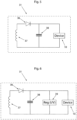
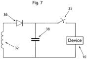
- the system comprises a capacitor 38 coupled to the implanted coil 32.
- the capacitor 38 is suitably arranged in the energy receiver 31, and is arranged in parallel with the implanted coil 32.
- the secondary coil is connected to the medical device 10 via a half wave rectifier, here shown as a diode 36, and the capacitor 38 is connected in parallel to the implanted coil 32 with the half wave rectifier between the capacitor and the implanted coil 32.
- the system is arranged to determine the total amount of energy, "E", stored in the capacitor 38, and the third parameter P3 comprises or is based on the total amount of energy, "E", stored in the capacitor, and the system is adapted to take into account the third parameter P3 in order to determine the amount of energy which should be transmitted by the external energy source. For example, if E is above a certain threshold value, this could be taken by the internal control unit 30 as an indication that the amount of energy to be transferred could be lowered or at least maintained at the same level, and if E is below the threshold value, this could be seen by the internal control unit 30 as an indication that the amount of energy to e transferred should be increased. Thus, it is suitably the internal control unit 30 that monitors the level of energy stored in the capacitor 38, and determines the third parameter P3.
- the medical device 10 also comprises a regulator 39 either a current regulator or a voltage regulator, which is thus arranged to keep a current or a voltage in the medical device constant.
- the system is arranged to determine a difference between an input voltage/current to the voltage/current regulator and the voltage or current which the regulator is arranged to keep constant.
- the system bases the feedback information from the internal control unit to the external control unit on a third parameter P3 parameter which comprises or is based on this voltage/current difference.
- the system is thus adapted to also take into account the "regulator" parameter P3 when determining the amount of energy which should be transmitted by the external energy source.
- the regulator 39 is a voltage regulator arranged to measure the voltage V over the medical device 10, as an alternative to which it can also be a current regulator arranged to measure the current I to the medical device 10.
- the system will further comprise an indicator in the external energy source, adapted to indicate a level of the coupling factor between the external coil 22 and the internal implanted coil 32.
- the same or another indicator in the external energy source is suitably used for indicating an optimal placement of the external coil 22 in relation to the implanted coil 32 in order to optimize the coupling factor.
- energy receiver comprises a switch 35 which is adapted to switch a connection between the implanted coil 32 and the medical device 10 on and off, in order to enable the system to measure the coupling factor when the connection is off.
- the internal control unit 30 handles the control of the switch 35.
- the energy receiver 31 comprises an electronic component which is connected to the secondary coil for preventing the flow of electrical current between the implanted coil 32 and the medical device 10 during measurement of parameters, for example parameters related to related to the coupling factor.
- these measurements are suitably carried out by the internal control unit 30, and the electronic component is the diode 36 which has been described previously.
- measurements can be carried out either when the diode is biased by the voltage caused by the inductive voltage over the implanted coil 32, or the control unit can cause the diode to be biased to block current to the medical device 10. If the diode 36 "blocks" the connection between the implanted coil 32 and the medical device 10, the implanted coil 32 will be substantially without an electrical load when the coupling factor is measured, which is beneficial for obtaining a good measurement result.
- the external energy source 20 comprises an electronic circuit (not shown) for comparing the feedback information with the amount of energy transmitted by the external energy source. Also, alternatively, this electronic circuit may be comprised in the control unit 20.
- the system also comprises an internal control unit, preferably the internal control unit 30, which is adapted to determine the energy balance between the energy received by the energy receiver 31 and the energy used by the medical device 10; in this embodiment the system also comprises an external control unit such as the control unit 20 which is adapted to calibrate the transmission of wireless energy from the external energy source 11 using feedback information.
- an internal control unit preferably the internal control unit 30, which is adapted to determine the energy balance between the energy received by the energy receiver 31 and the energy used by the medical device 10
- the system also comprises an external control unit such as the control unit 20 which is adapted to calibrate the transmission of wireless energy from the external energy source 11 using feedback information.
- the system comprises at least one energy stabilizing unit in or connected to the medical device 10, arranged to stabilize received energy prior to use by the medical device 10.
- Fig. 8a another view of a chargeable medical system is depicted.
- the system comprises an implanted coil 32 implanted in a patient.
- the implanted coil 32 is adapted to receive wireless energy from an external coil 22 through the skin 4 of the patient in accordance with the above.
- the internal charger is connected to an internal energy supply such as a battery 30.
- the internal energy supply supplies energy used for driving an implanted medical device 10.
- the implanted medical device 10 can be operated using a mechanically or hydraulically controlled control device.
- the implanted medical device can be adapted to mechanically or hydraulically adjust a member 108 located in conjunction with a blood vessel 112 or some other internal organ 112 for controlling the flow in the vessel or organ 112.
- the member 108 is mechanically or hydraulically adjusted to a generally closed position.
- FIG. 8b another view of the chargeable medical device 10 is depicted.
- the view in Fig. 8b corresponds the view in Fig. 8a but with the member 108 mechanically or hydraulically adjusted to a generally open position.
- Fig. 9 a view further illustrating the operation of a charger system as described herein.
- the external control unit 20 is moved of the skin of the patient.
- the optimal position for charging the implanted medical device is selected. The operation is further described below in conjunction with Fig. 10 .
- Fig. 10 a flow chart illustrating steps performed when using the system as described herein in order to find an optimal position for charging an internal charger for supplying power to an implanted medical device.
- the external charger is turned on.
- the charger runs through a calibration procedure for producing a response from the internal charger.
- the user starts to move the external charger over the skin of the patient.
- the user receives feedback information from the system enabling the user to move the external charger to a more favorable position.
- the charger indicates that in a step 609 and the procedure ends in a step 611.
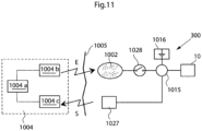
- Fig. 11 another view of an implanted chargeable medical device 10 is depicted.
- the patient's skin is indicated by a vertical line 1005.
- the internal charger in the form of an energy receiver comprises an energy-transforming device 1002 located inside the patient.
- the energy receiver such as a coil can preferably be located just beneath the patient's skin 1005.
- the implanted energy-transforming device 1002 may be placed in the abdomen, thorax, muscle fascia (e.g. in the abdominal wall), subcutaneously, or at any other suitable location.
- the implanted energy-transforming device 1002 is adapted to receive wireless energy E transmitted from an external energy-source 1004a, in particular an external charger such as a coil provided in an external energy-transmission device 1004 located outside the patient's skin 1005 in the vicinity of the implanted energy-transforming device 1002.
- an external charger such as a coil provided in an external energy-transmission device 1004 located outside the patient's skin 1005 in the vicinity of the implanted energy-transforming device 1002.
- the wireless energy E may generally be transferred by means of any suitable Transcutaneous Energy Transfer (TET) device, such as a device including a primary coil arranged in the external energy source 1004a and an adjacent secondary coil arranged in the implanted energy-transforming device 1002.
- TET Transcutaneous Energy Transfer
- TET Transcutaneous Energy Transfer
- the present disclosure is generally not limited to any particular energy transfer technique, TET devices or energy sources, and any kind of wireless energy may be used.
- the amount of energy received by the implanted energy receiver may be compared with the energy used by the implanted components of the apparatus.
- the term "energy used” is then understood to include also energy stored by implanted components of the apparatus.
- a control device includes an external control unit 1004b that controls the external energy source 1004a based on the determined energy balance to regulate the amount of transferred energy. In order to transfer the correct amount of energy, the energy balance and the required amount of energy is determined by means of a determination device including an implanted internal control unit 1015 connected between a switch 1026 and an implanted medical device 10.
- the internal control unit 1015 may thus be arranged to receive various measurements obtained by suitable sensors or the like, not shown, measuring certain characteristics of the implanted medical device 10, somehow reflecting the required amount of energy needed for proper operation of the implanted medical device 10.
- the current condition of the patient may also be detected by means of suitable measuring devices or sensors, in order to provide parameters reflecting the patient's condition.
- characteristics and/or parameters may be related to the current state of the implanted medical device, such as power consumption, operational mode and temperature, as well as the patient's condition reflected by parameters such as; body temperature, blood pressure, heartbeats and breathing.
- Other kinds of physical parameters of the patient and functional parameters of the device are described elsewhere.
- an energy source in the form of an accumulator 1016 may optionally be connected to the implanted energy-transforming device 1002 via the control unit 1015 for accumulating received energy for later use by the implanted medical device.
- characteristics of such an accumulator also reflecting the required amount of energy, may be measured as well.
- the accumulator may be replaced by a rechargeable battery, and the measured characteristics may be related to the current state of the battery, any electrical parameter such as energy consumption voltage, temperature, etc. In order to provide sufficient voltage and current to the implanted medical device 10, and also to avoid excessive heating, it is clearly understood that the battery should be charged optimally by receiving a correct amount of energy from the implanted energy-transforming device 1002, i.e. not too little or too much.
- the accumulator may also be a capacitor with corresponding characteristics.
- battery characteristics may be measured on a regular basis to determine the current state of the battery, which then may be stored as state information in a suitable storage means in the internal control unit 1015.
- state information in a suitable storage means in the internal control unit 1015.
- the internal control unit 1015 of the determination device is adapted to determine the energy balance and/or the currently required amount of energy, (either energy per time unit or accumulated energy) based on measurements made by the above-mentioned sensors or measuring devices of the implantable medical device 10, or the patient, or an implanted energy source if used, or any combination thereof.
- the internal control unit 1015 can further be connected to an internal signal transmitter 1027, arranged to transmit a control signal reflecting the determined required amount of energy, to an external signal receiver 1004c connected to the external control unit 1004b. The amount of energy transmitted from the external energy source 1004a may then be regulated in response to the received control signal.
- the determination device may include the external control unit 1004b.
- sensor measurements can be transmitted directly to the external control unit 1004b wherein the energy balance and/or the currently required amount of energy can be determined by the external control unit 1004b, thus integrating the above-described function of the internal control unit 1015 in the external control unit 1004b.
- the internal control unit 1015 can be omitted and the sensor measurements are supplied directly to the internal signal transmitter 1027 which sends the measurements over to an external signal receiver 1004c and the external control unit 1004b. The energy balance and the currently required amount of energy can then be determined by the external control unit 1004b based on those sensor measurements.
- the system in accordance with the arrangement depicted in Fig. 11 employs the feed back of information indicating the required energy, which is more efficient than previous solutions because it is based on the actual use of energy that is compared to the received energy, e.g. with respect to the amount of energy, the energy difference, or the energy receiving rate as compared to the energy rate used by implanted energy consuming components of the apparatus.
- the apparatus may use the received energy either for consuming or for storing the energy in an implanted energy source or the like.
- the different parameters discussed above would thus be used if relevant and needed and then as a tool for determining the actual energy balance. However, such parameters may also be needed per se for any actions taken internally to specifically operate the apparatus.
- the internal signal transmitter 1027 and the external signal receiver 1004c may be implemented as separate units using suitable signal transfer means, such as radio, IR (Infrared) or ultrasonic signals.
- suitable signal transfer means such as radio, IR (Infrared) or ultrasonic signals.
- the internal signal transmitter 1027 and the external signal receiver 1004c may be integrated in the implanted energy-transforming device 1002 and the external energy source 1004a, respectively, so as to convey control signals in a reverse direction relative to the energy transfer, basically using the same transmission technique.
- the control signals may be modulated with respect to frequency, phase or amplitude.
- the feedback information may be transferred either by a separate communication system including receivers and transmitters or may be integrated in the energy system.
- an integrated information feedback and energy system comprises an implantable internal energy receiver for receiving wireless energy, the energy receiver having an internal first coil and a first electronic circuit connected to the first coil, and an external energy transmitter for transmitting wireless energy, the energy transmitter having an external second coil and a second electronic circuit connected to the second coil.
- the external second coil of the energy transmitter transmits wireless energy which is received by the first coil of the energy receiver.
- This system further comprises a power switch for switching the connection of the internal first coil to the first electronic circuit on and off, such that feedback information related to the charging of the first coil is received by the external energy transmitter in the form of an impedance variation in the load of the external second coil, when the power switch switches the connection of the internal first coil to the first electronic circuit on and off.
- the switch 1026 can either be separate and controlled by the internal control unit 1015, or integrated in the internal control unit 1015. It should be understood that the switch 1026 can be implemented by any type of suitable device such as a transistor, MCU, MCPU, ASIC FPGA or a DA converter or any other electronic component or circuit that may switch the power on and off.
- the energy supply arrangement illustrated in Fig. 7 may be operated in the following manner.
- the energy balance is first determined by the internal control unit 1015 of the determination device.
- a control signal reflecting the required amount of energy is also created by the internal control unit 1015, and the control signal is transmitted from the internal signal transmitter 1027 to the external signal receiver 1004c.
- the energy balance can be determined by the external control unit 1004b instead depending on the implementation, as mentioned above.
- the control signal may carry measurement results from various sensors.
- the amount of energy emitted from the external energy source 1004a can then be regulated by the external control unit 1004b, based on the determined energy balance, e.g. in response to the received control signal. This process may be repeated intermittently at certain intervals during ongoing energy transfer, or may be executed on a more or less continuous basis during the energy transfer.
- the amount of transferred energy can generally be regulated by adjusting various transmission parameters in the external energy source 1004a, such as voltage, current, amplitude, wave frequency and pulse characteristics.
- the system as described herein above may also be used to obtain information about the coupling factors between the coils in a TET system even to calibrate the system both to find an optimal place for the external coil in relation to the internal coil and to optimize energy transfer. Simply comparing in this case the amount of energy transferred with the amount of energy received. For example if the external coil is moved the coupling factor may vary and correctly displayed movements could cause the external coil to find the optimal place for energy transfer.
- the external coil is adapted to calibrate the amount of transferred energy to achieve the feedback information in the determination device, before the coupling factor is maximized.
- the energy system comprises an implantable internal energy receiver for receiving wireless energy, the energy receiver having an internal first coil and a first electronic circuit connected to the first coil, and an external energy transmitter for transmitting wireless energy, the energy transmitter having an external second coil and a second electronic circuit connected to the second coil.
- the external second coil of the energy transmitter transmits wireless energy which is received by the first coil of the energy receiver.
- This system further comprises a feedback device for communicating out the amount of energy received in the first coil as a feedback information
- the second electronic circuit includes a determination device for receiving the feedback information and for comparing the amount of transferred energy by the second coil with the feedback information related to the amount of energy received in the first coil to obtain the coupling factor between the first and second coils.
- the energy transmitter may regulate the transmitted energy in response to the obtained coupling factor.
- Fig. 12 illustrates different examples for how received energy can be supplied to and used by the implantable medical device 10.
- an internal energy receiver 1002 receives wireless energy E from an external energy source 1004a which is controlled by a transmission control unit 1004b.
- the internal energy receiver 1002 may comprise a constant voltage circuit, indicated as a dashed box “constant V" in the figure, for supplying energy at constant voltage to the implantable medical device 10.
- the internal energy receiver 1002 may further comprise a constant current circuit, indicated as a dashed box "constant C" in the figure, for supplying energy at constant current to the implantable medical device 10.
- the implantable medical device 10 can comprise an energy consuming part 10a for example a motor, a pump, a restriction device, or any other medical appliance that requires energy for its electrical operation.
- the implantable medical device 10 may further comprise an energy storage device 10b for storing energy supplied from the internal energy receiver 1002.
- the supplied energy may be directly consumed by the energy consuming part 10a, or stored by the energy storage device 10b, or the supplied energy may be partly consumed and partly stored.
- the implantable medical device 10 may further comprise an energy stabilizing unit 10c for stabilizing the energy supplied from the internal energy receiver 1002.
- the energy may be supplied in a fluctuating manner such that it may be necessary to stabilize the energy before consumed or stored.
- the energy supplied from the internal energy receiver 1002 may further be accumulated and/or stabilized by a separate energy stabilizing unit 1028 located outside the implantable medical device 10, before being consumed and/or stored by the implantable medical device 10.
- the energy stabilizing unit 1028 may be integrated in the internal energy receiver 1002.
- the energy stabilizing unit 1028 may comprise a constant voltage circuit and/or a constant current circuit.
- Fig. 13 schematically shows an energy balance measuring circuit of one of the proposed designs of the system for controlling transmission of wireless energy, or energy balance control system.
- the circuit has an output signal centered on 2.5V and proportionally related to the energy imbalance. The derivative of this signal shows if the value goes up and down and how fast such a change takes place. If the amount of received energy is lower than the energy used by implanted components of the device, more energy is transferred and thus charged into the energy source.
- the output signal from the circuit is typically feed to an A/D converter and converted into a digital format. The digital information can then be sent to the external energy-transmission device allowing it to adjust the level of the transmitted energy.
- Another possibility is to have a completely analog system that uses comparators comparing the energy balance level with certain maximum and minimum thresholds sending information to external energy-transmission device if the balance drifts out of the max/min window.
- the schematic Fig. 13 shows a circuit implementation for a system that transfers energy to the implanted energy components of the device from outside of the patient's body using inductive energy transfer.
- An inductive energy transfer system typically uses an external transmitting coil and an internal receiving coil.
- the receiving coil, L1 is included and the transmitting parts of the system are excluded.
- Fig. 13 the symbols Y1, Y2, Y3 and so on symbolize test points within the circuit.
- the components in the diagram and their respective values are values that work in this particular implementation which of course is only one of an infinite number of possible design solutions.
- Energy to power the circuit is received by the energy receiving coil L1.
- Energy to implanted components is transmitted in this particular case at a frequency of 25 kHz.
- the energy balance output signal is present at test point Y1.
- the examples described above identify a method and a system for controlling transmission of wireless energy to implanted energy consuming components of an electrically powered implantable medical device.
- a method which is not part of the present invention is thus provided for controlling transmission of wireless energy supplied to implanted energy consuming components of a device as described above.
- the wireless energy E is transmitted from an external energy source located outside the patient and is received by an internal energy receiver located inside the patient, the internal energy receiver being connected to the implanted energy consuming components of the device for directly or indirectly supplying received energy thereto.
- An energy balance is determined between the energy received by the internal energy receiver and the energy used for the device.
- the transmission of wireless energy E from the external energy source is then controlled based on the determined energy balance.
- the wireless energy may be transmitted inductively from a primary coil in the external energy source to a secondary coil in the internal energy receiver.
- a change in the energy balance may be detected to control the transmission of wireless energy based on the detected energy balance change.
- a difference may also be detected between energy received by the internal energy receiver and energy used for the medical device, to control the transmission of wireless energy based on the detected energy difference.
- the amount of transmitted wireless energy may be decreased if the detected energy balance change implies that the energy balance is increasing, or vice versa.
- the decrease/increase of energy transmission may further correspond to a detected change rate.
- the amount of transmitted wireless energy may further be decreased if the detected energy difference implies that the received energy is greater than the used energy, or vice versa.
- the decrease/increase of energy transmission may then correspond to the magnitude of the detected energy difference.
- the energy used for the medical device may be consumed to operate the medical device, and/or stored in at least one energy storage device of the medical device.
- the energy may be transmitted for consumption and storage according to a transmission rate per time unit which is determined based on said parameters.
- the total amount of transmitted energy may also be determined based on said parameters.
- the integral may be determined for a monitored voltage and/or current related to the energy balance.
- the derivative When the derivative is determined over time of a measured electrical parameter related to the amount of consumed and/or stored energy, the derivative may be determined for a monitored voltage and/or current related to the energy balance.
- the transmission of wireless energy from the external energy source may be controlled by applying to the external energy source electrical pulses from a first electric circuit to transmit the wireless energy, the electrical pulses having leading and trailing edges, varying the lengths of first time intervals between successive leading and trailing edges of the electrical pulses and/or the lengths of second time intervals between successive trailing and leading edges of the electrical pulses, and transmitting wireless energy, the transmitted energy generated from the electrical pulses having a varied power, the varying of the power depending on the lengths of the first and/or second time intervals.
- the frequency of the electrical pulses may be substantially constant when varying the first and/or second time intervals.
- the electrical pulses may remain unchanged, except for varying the first and/or second time intervals.
- the amplitude of the electrical pulses may be substantially constant when varying the first and/or second time intervals. Further, the electrical pulses may be varied by only varying the lengths of first time intervals between successive leading and trailing edges of the electrical pulses.
- a train of two or more electrical pulses may be supplied in a row, wherein when applying the train of pulses, the train having a first electrical pulse at the start of the pulse train and having a second electrical pulse at the end of the pulse train, two or more pulse trains may be supplied in a row, wherein the lengths of the second time intervals between successive trailing edge of the second electrical pulse in a first pulse train and leading edge of the first electrical pulse of a second pulse train are varied.
- the electrical pulses When applying the electrical pulses, the electrical pulses may have a substantially constant current and a substantially constant voltage.
- the electrical pulses may also have a substantially constant current and a substantially constant voltage. Further, the electrical pulses may also have a substantially constant frequency.
- the electrical pulses within a pulse train may likewise have a substantially constant frequency.
- the circuit formed by the first electric circuit and the external energy source may have a first characteristic time period or first time constant, and when effectively varying the transmitted energy, such frequency time period may be in the range of the first characteristic time period or time constant or shorter.
- a system comprising a device as described above is thus also provided for controlling transmission of wireless energy supplied to implanted energy consuming components of the device.
- the system comprises a control device for controlling the transmission of wireless energy from an energy-transmission device, and an implantable internal energy receiver for receiving the transmitted wireless energy, the internal energy receiver being connected to implantable energy consuming components of the device for directly or indirectly supplying received energy thereto.
- the system further comprises a determination device adapted to determine an energy balance between the energy received by the internal energy receiver and the energy used for the implantable energy consuming components of the device, wherein the control device controls the transmission of wireless energy from the external energy-transmission device, based on the energy balance determined by the determination device.
- system may comprise any of the following:
- the device as described herein can be implanted in a patient using some suitable surgical procedure as depicted in Fig. 14 .
- the device can be implanted by inserting a needle or a tube like instrument into the patient's abdominal cavity, step 1201.
- a step 1203 a part of the patient's body with gas using the needle or tube like instrument thereby expanding said abdominal cavity.
- a step 1205 at least two laparoscopic trocars are placed in the cavity.
- a camera is inserted through one of the laparoscopic trocars into the cavity.
- a step 1209 at least one dissecting tool is inserted through one of said at least two laparoscopic trocars.
- An area where the device is to be placed is then dissected in a step 1211.
- the device is then placed in the area in a step 1213, and the device is enabled in a step 1215.
- the device can be implanted by a procedure depicted in Fig. 15 .
- a needle or a tube like instrument is inserted into the patient's thoraxial cavity.
- a part of the patient's body with gas using the needle or tube like instrument to fill and thereby expanding the thoraxial cavity.
- at least two laparoscopic trocars are placed in said cavity in a step 1305
- a camera is inserted through one of the laparoscopic trocars into the cavity.
- at least one dissecting tool is inserted through one of said at least two laparoscopic trocars.
- An area is then dissected in a step 1311.
- the device is then placed in the area in a step 1313, and the device is enabled in a step 1315.
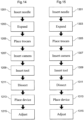
- the device can be implanted by a procedure depicted in Fig. 16 .
- a procedure depicted in Fig. 16 First in a step 1401, the skin in the abdominal or thoraxial wall of the mammal patient is cut. Next, in a step 1403 an area is dissected. Next, the device is then placed in the area in a step 1405, and the device is enabled in a step 1407.
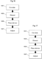
- the device can be implanted by a procedure depicted in Fig. 17 .
- the device is then placed in the area in a step 1505, and the pressure that the device is enabled in a step 1507.
Landscapes
- Engineering & Computer Science (AREA)
- Health & Medical Sciences (AREA)
- General Health & Medical Sciences (AREA)
- Animal Behavior & Ethology (AREA)
- Veterinary Medicine (AREA)
- Public Health (AREA)
- Physics & Mathematics (AREA)
- Biomedical Technology (AREA)
- Nuclear Medicine, Radiotherapy & Molecular Imaging (AREA)
- Radiology & Medical Imaging (AREA)
- Life Sciences & Earth Sciences (AREA)
- Power Engineering (AREA)
- Acoustics & Sound (AREA)
- Electromagnetism (AREA)
- Computer Networks & Wireless Communication (AREA)
- Electrotherapy Devices (AREA)
- Prostheses (AREA)
Claims (15)
- Medizinisches Implantat, umfassend:eine erste Spule (32), die aus einem Draht gewunden ist und ausgestaltet ist, um drahtlose Energie oder drahtlose Kommunikation zu empfangen, wobei die erste Spule einen ersten Durchmesser aufweist,der eine Vielzahl großer Windungen umfasst, die um eine Längsachse gewunden sind, wobei jede große Windung eine Vielzahl von dritten Spulen umfasst,die in Reihe oder parallel verbunden sind, wobei jede dritte Spule einen Durchmesser aufweist, der kleiner als der erste Durchmesser ist.
- Medizinisches Implantat nach Anspruch 1, wobei die dritten Spulen jeweils eine Zentralachse haben, die senkrecht zu der Längsachse ist.
- Medizinisches Implantat nach dem vorhergehenden Anspruch, des Weiteren umfassend:eine interne Energieversorgung, um eine medizinische Vorrichtung, die in einen Patienten implantiert ist, mit Energie zu versorgen,wobei die erste Spule in der internen Ladeeinrichtung enthalten ist und ausgestaltet ist, um die interne Energieversorgung zu laden.
- Medizinisches Implantat nach dem vorhergehenden Anspruch, des Weiteren umfassend:
eine erste Steuereinheit (30), die, wenn sie in den Körper des Patienten implantiert ist, mit der ersten Spule verbunden ist, um den Empfang von Energie oder drahtloser Kommunikation von der ersten Spule zu steuern. - Medizinisches Implantat nach einem der vorhergehenden Ansprüche, wobei der helixförmige Draht für mindestens eines der folgenden eingerichtet ist:• zum Winden in kompakter Weise, wie ein Rohr,• zur Verwendung zum Winden der Vielzahl großer Windungen der ersten Spule, und• zum Bewirken, dass die erste Spule flexibel ist.
- Medizinisches Implantat nach einem der vorhergehenden Ansprüche, wobei die erste Spule eingerichtet ist, um subkutan platziert zu werden.
- Medizinisches Implantat nach einem der vorhergehenden Ansprüche, wobei eine in der ersten Spule induzierte Wechselspannung bewirkt, dass eine elektrische Ladung in der ersten Spule an eine Lastschaltung fließt, die mit der ersten Spule verbunden ist, um so Energie von einer externen zweiten Spule durch die erste Spule hindurch an die mit der ersten Spule verbundene Lastschaltung zu übertragen, wobei die Lastschaltung des Weiteren aus mindestens einem der folgenden zusammengesetzt ist:• einer Energieversorgung, die, wenn sie in den Körper des Patienten implantiert ist, die implantierte medizinische Vorrichtung mit Energie versorgt,• der medizinischen Vorrichtung, die von der ersten Spule direkt mit Energie versorgt wird, wenn sie in den Körper des Patienten implantiert ist,• der ersten Steuereinheit, die, wenn sie in den Körper des Patienten implantiert ist, die implantierte medizinische Vorrichtung mit Steuersignalen versorgt,• der ersten Steuereinheit, die, wenn sie in den Körper des Patienten implantiert ist, Informationssignale von der implantierten medizinischen Vorrichtung empfängt.
- Medizinisches Implantat nach einem der vorhergehenden Ansprüche, wobei die erste Spule des Weiteren ausgestaltet ist, um Steuersignale zu empfangen, wobei die Steuersignale mindestens eines der folgenden betreffen:• Körperfunktionen, die von der medizinischen Vorrichtung überwacht werden, oder Körperfunktionen, die von der medizinischen Vorrichtung gesteuert werden, und• funktionale Parameter der medizinischen Vorrichtung, die durch die medizinische Vorrichtung überwacht werden, oder funktionale Parameter der medizinischen Vorrichtung, die durch die medizinische Vorrichtung gesteuert werden.
- Medizinisches Implantat nach einem der vorhergehenden Ansprüche, wobei die erste Spule des Weiteren ausgestaltet ist, um Informationssignale zu empfangen, wobei die Informationssignale mindestens eines der folgenden betreffen:• Körperfunktionen, die von der implantierten medizinischen Vorrichtung überwacht werden, oder Körperfunktionen, die von der implantierten medizinischen Vorrichtung gesteuert werden, und• funktionale Parameter der medizinischen Vorrichtung, die durch die medizinische Vorrichtung überwacht werden, oder funktionale Parameter der medizinischen Vorrichtung, die durch die medizinische Vorrichtung gesteuert werden.
- Medizinisches Implantat nach Anspruch 4, wobei die erste Steuereinheit aus einem Generator zum Generieren eines alternierenden elektromagnetischen Signals, einem Leistungsverstärker, einer Modulatorschaltung und einem Mikroprozessor zum Steuern der Modulatorschaltung zusammengesetzt ist, um dadurch Informationssignale zu generieren, die von der medizinischen Vorrichtung gesendet werden sollen, wobei der Mikroprozessor den Generator und die Modulatorschaltung steuert, um Signale zu modulieren, die von dem Generator generiert wurden, um dadurch Körperinformationen von der medizinischen Vorrichtung über den Leistungsverstärker und die zweite Spule, die mit dem Leistungsverstärker verbunden ist, an eine externe zweite Steuereinheit zu senden
- Medizinisches Implantat nach einem der vorhergehenden Ansprüche, wobei die erste Steuereinheit des Weiteren eine Demodulatorschaltung umfasst, die mit der ersten Spule verbunden ist und Steuersignale demoduliert, die durch die erste Spule empfangen wurden, um so Steuerinformationen, die von der zweiten Steuereinheit gesendet wurden, zu entfernen.
- System zum Versorgen eines Implantats mit Energie, wenn dieses in einen Säugerpatienten implantiert ist, umfassend:das medizinische Implantat nach dem vorhergehenden Anspruch, undeine zweite Spule (22) extern zu dem Körper des Patienten, welche die drahtlose Energie an die erste Spule überträgt, wenn diese in den Körper des Patienten implantiert ist, undeine zweite Steuereinheit (20), die sich außerhalb des Körpers des Patienten befindet und mit der zweiten Spule verbunden ist und Energie zur Übertragung an die erste Spule generiert.
- System nach Anspruch 12, wobei die zweite Steuereinheit des Weiteren aus einer Demodulatorschaltung zusammengesetzt ist, die mit der zweiten Spule verbunden ist und Informationssignale demoduliert, die durch die zweite Spule empfangen wurden, um so Körperinformationen, die von der medizinischen Vorrichtung gesendet wurden, zu entfernen.
- System nach Anspruch 13, wobei ein durch die zweite Steuereinheit generiertes alternierendes Signal ein Wechselstrom ist, der durch die zweite Spule fließt, und wobei die durch die erste Spule empfangene drahtlose Energie ein magnetisches Wechselfeld ist, das durch den in der zweiten Spule fließenden Wechselstrom erzeugt wird, und das eine Wechselspannung in der ersten Spule induziert.
- Medizinisches Implantat nach Anspruch 13 oder 14, wobei die zweite Steuereinheit aus einem Generator zum Generieren eines alternierenden elektromagnetischen Signals, einem Leistungsverstärker, einer Modulatorschaltung und einem Mikroprozessor zum Steuern der Modulatorschaltung zusammengesetzt ist, um dadurch die Steuersignale zu generieren, die zu der medizinischen Vorrichtung gesendet werden sollen, wobei der Mikroprozessor den Generator und die Modulatorschaltung steuert, um Signale zu modulieren, die von dem Generator generiert wurden, um dadurch Steuerinformationen über den Leistungsverstärker und die zweite Spule, die mit dem Leistungsverstärker verbunden ist, an die medizinische Vorrichtung zu senden.
Applications Claiming Priority (7)
| Application Number | Priority Date | Filing Date | Title |
|---|---|---|---|
| US19336808P | 2008-11-21 | 2008-11-21 | |
| SE0900636 | 2009-05-11 | ||
| US21322509P | 2009-05-19 | 2009-05-19 | |
| US21380509P | 2009-07-17 | 2009-07-17 | |
| SE0901002 | 2009-07-17 | ||
| EP09827812.0A EP2385860B1 (de) | 2008-11-21 | 2009-11-23 | System zur energieversorgung einer implantierbaren medizinischen vorrichtung |
| PCT/SE2009/000501 WO2010059097A1 (en) | 2008-11-21 | 2009-11-23 | System, method and apparatus f or supplying energy to an implantable medical device |
Related Parent Applications (1)
| Application Number | Title | Priority Date | Filing Date |
|---|---|---|---|
| EP09827812.0A Division EP2385860B1 (de) | 2008-11-21 | 2009-11-23 | System zur energieversorgung einer implantierbaren medizinischen vorrichtung |
Publications (3)
| Publication Number | Publication Date |
|---|---|
| EP3875143A1 EP3875143A1 (de) | 2021-09-08 |
| EP3875143C0 EP3875143C0 (de) | 2023-06-07 |
| EP3875143B1 true EP3875143B1 (de) | 2023-06-07 |
Family
ID=42198348
Family Applications (2)
| Application Number | Title | Priority Date | Filing Date |
|---|---|---|---|
| EP20215955.4A Active EP3875143B1 (de) | 2008-11-21 | 2009-11-23 | System zur energieversorgung einer implantierbaren medizinischen vorrichtung |
| EP09827812.0A Active EP2385860B1 (de) | 2008-11-21 | 2009-11-23 | System zur energieversorgung einer implantierbaren medizinischen vorrichtung |
Family Applications After (1)
| Application Number | Title | Priority Date | Filing Date |
|---|---|---|---|
| EP09827812.0A Active EP2385860B1 (de) | 2008-11-21 | 2009-11-23 | System zur energieversorgung einer implantierbaren medizinischen vorrichtung |
Country Status (4)
| Country | Link |
|---|---|
| US (1) | US8862241B2 (de) |
| EP (2) | EP3875143B1 (de) |
| ES (1) | ES2951139T3 (de) |
| WO (1) | WO2010059097A1 (de) |
Families Citing this family (54)
| Publication number | Priority date | Publication date | Assignee | Title |
|---|---|---|---|---|
| AU2002952691A0 (en) | 2002-11-15 | 2002-11-28 | Sunshine Heart Company Pty Ltd | Heart assist device utilising aortic deformation |
| ES2561354T3 (es) | 2003-10-31 | 2016-02-25 | Sunshine Heart Company Pty Ltd | Sistema de control de sincronización |
| WO2009048386A1 (en) * | 2007-10-12 | 2009-04-16 | Milux Holding Sa | An ostomy accessory |
| MX2010004087A (es) | 2007-10-16 | 2010-08-11 | Milux Holding Sa | Metodo y aparato para suministrar energia a un dispositivo medico. |
| WO2009051538A1 (en) * | 2007-10-16 | 2009-04-23 | Milux Holding Sa | A method and apparatus for supplying energy to a medical device |
| BRPI0819622B8 (pt) * | 2007-11-27 | 2021-06-22 | Implantica Patent Ltd | controle de transferência de energia adaptado para um sistema de dispositivo médico |
| WO2010042052A1 (en) | 2008-10-10 | 2010-04-15 | Milux Holding S.A. | Method and apparatus for supplying energy to an implant |
| US9259583B2 (en) | 2009-07-17 | 2016-02-16 | Peter Forsell | Coil system |
| CA2805339C (en) | 2009-07-17 | 2020-12-22 | Milux Holding S.A. | An improved medical system comprising implants |
| US9107684B2 (en) * | 2010-03-05 | 2015-08-18 | Covidien Lp | System and method for transferring power to intrabody instruments |
| US20110270331A1 (en) | 2010-04-02 | 2011-11-03 | Sunshine Heart Company Pty Ltd | Combination heart assist systems, methods, and devices |
| WO2013009881A2 (en) | 2011-07-11 | 2013-01-17 | Vascor, Inc. | Transcutaneous power transmission and communication for implanted heart assist and other devices |
| US8700175B2 (en) * | 2011-07-19 | 2014-04-15 | Greatbatch Ltd. | Devices and methods for visually indicating the alignment of a transcutaneous energy transfer device over an implanted medical device |
| US9343224B2 (en) * | 2011-08-19 | 2016-05-17 | Leviticus Cardio Ltd. | Coplanar energy transfer |
| US10543303B2 (en) | 2013-11-08 | 2020-01-28 | Leviticus Cardio Ltd. | Batteries for use in implantable medical devices |
| US9793579B2 (en) | 2013-11-08 | 2017-10-17 | Leviticus Cardio Ltd. | Batteries for use in implantable medical devices |
| US9186520B2 (en) | 2012-01-16 | 2015-11-17 | Boston Scientific Neuromodulation Corporation | Automatic on-off charger for an implantable medical device |
| CN104487131A (zh) * | 2012-03-13 | 2015-04-01 | 阳光心脏有限公司 | 关于无线电力传输的方法系统和设备 |
| JP6066259B2 (ja) * | 2012-04-06 | 2017-01-25 | 学校法人東京理科大学 | 体内局所加温装置 |
| KR101950688B1 (ko) * | 2012-07-09 | 2019-02-21 | 삼성전자주식회사 | 무선 전력 송신기 및 그 제어 방법 |
| US9225190B2 (en) | 2012-09-07 | 2015-12-29 | Manufacturers And Traders Trust Company | Implant current controlled battery charging based on temperature |
| US9142989B2 (en) | 2012-09-07 | 2015-09-22 | Greatbatch Ltd. | Method of minimizing interruptions to implantable medical device recharging |
| US9209634B2 (en) | 2012-09-07 | 2015-12-08 | Greatbatch Ltd. | Method of improving battery recharge efficiency by statistical analysis |
| DE102013100175A1 (de) * | 2013-01-09 | 2014-07-10 | Epcos Ag | Spulenanordnung zum Induzieren und Bereitstellen einer Spannung zum Aufladen eines Ladungsspeichers |
| JP6553623B2 (ja) | 2013-09-16 | 2019-07-31 | ザ ボード オブ トラスティーズ オブ ザ レランド スタンフォード ジュニア ユニバーシティー | 電磁エネルギー生成のための多素子カプラ |
| EP3753517B1 (de) | 2014-05-18 | 2022-05-11 | Neuspera Medical Inc. | Mittelfeldkoppler |
| US20160336813A1 (en) | 2015-05-15 | 2016-11-17 | NeuSpera Medical Inc. | Midfield coupler |
| DE102014118040B4 (de) * | 2014-12-05 | 2017-08-24 | Fraunhofer-Gesellschaft zur Förderung der angewandten Forschung e.V. | Regelschaltung für eine Basisstation zum Übertragen einer Energie auf einen Empfänger mittels eines elektrischen Schwingkreises, Auswerteeinrichtung, Verfahren und Computerprogramm |
| US9876386B2 (en) | 2015-04-29 | 2018-01-23 | Fp Wireless Llc | Wirelessly powered door lock systems and methods |
| US10135288B2 (en) | 2015-04-29 | 2018-11-20 | Fp Wireless Llc | Electronic control module and driver module for controlling an electronic lock module |
| US20160322847A1 (en) | 2015-04-29 | 2016-11-03 | Fp Wireless Llc | Wireless Battery Charging Systems And Methods |
| GB201513596D0 (en) | 2015-07-31 | 2015-09-16 | Univ Ulster The | Transcutaneous energy transfer systems and methods |
| US10049517B2 (en) | 2016-01-27 | 2018-08-14 | FP Wireless, LLC | Wirelessly charged electronic lock with open/closed status reporting |
| USD876628S1 (en) | 2016-07-20 | 2020-02-25 | Nyxoah S.A. | Medical implant |
| USD988519S1 (en) | 2016-09-12 | 2023-06-06 | Nyxoah S.A. | Patch |
| US11707623B2 (en) | 2017-02-28 | 2023-07-25 | Nyxoah S.A. | Surgical implant system |
| US10980689B2 (en) | 2017-07-14 | 2021-04-20 | Stryker Corporation | Patient support apparatuses with personal electronic device charging |
| US11394252B2 (en) | 2017-10-24 | 2022-07-19 | Stryker Corporation | Power transfer system with patient support apparatus and power transfer device to transfer power to the patient support apparatus |
| US10910888B2 (en) | 2017-10-24 | 2021-02-02 | Stryker Corporation | Power transfer system with patient transport apparatus and power transfer device to transfer power to the patient transport apparatus |
| US11389357B2 (en) | 2017-10-24 | 2022-07-19 | Stryker Corporation | Energy storage device management for a patient support apparatus |
| US11139666B2 (en) | 2017-10-24 | 2021-10-05 | Stryker Corporation | Energy harvesting and propulsion assistance techniques for a patient support apparatus |
| US10797524B2 (en) | 2017-10-24 | 2020-10-06 | Stryker Corporation | Techniques for power transfer through wheels of a patient support apparatus |
| KR102387573B1 (ko) * | 2017-12-12 | 2022-04-18 | 삼성전자주식회사 | 내부 장치, 외부 장치, 사용자 단말 및 전자 장치 및 이들의 동작 방법 |
| US11241582B2 (en) * | 2018-05-22 | 2022-02-08 | Medtronic, Inc. | Externally powered implantable stimulator |
| CN108744274B (zh) * | 2018-06-15 | 2021-07-16 | 常州瑞神安医疗器械有限公司 | 一种磁感应控制的体内植入医疗装置控制系统 |
| US11056267B2 (en) * | 2018-06-28 | 2021-07-06 | Medtronic, Inc. | Receive coil configurations for implantable medical device |
| US10821292B2 (en) | 2018-06-28 | 2020-11-03 | Medtronic, Inc. | Multi-axis coil for implantable medical device |
| US11045658B2 (en) * | 2018-06-28 | 2021-06-29 | Medtronic, Inc. | Receive coil configurations for implantable medical device |
| US11490813B2 (en) * | 2019-06-25 | 2022-11-08 | St. Jude Medical Luxembourg Holdings Ii S.A.R.L. (“Sjm Lux 11”) | Method and system for managing energy transfer between a passive implanted medical device and external device |
| US11063479B1 (en) | 2020-04-07 | 2021-07-13 | Medtronic, Inc. | Method of detecting presence of implanted power transfer coil |
| EP4016797A1 (de) * | 2020-12-15 | 2022-06-22 | Capri Medical Limited | Systeme zur drahtlosen stromübertragung für eine implantierbare medizinische vorrichtung |
| US12403318B2 (en) | 2021-11-24 | 2025-09-02 | Medtronic, Inc. | Ceramic enclosure for rechargeable medical devices |
| KR20230108891A (ko) | 2022-01-12 | 2023-07-19 | 삼성전자주식회사 | 생체 삽입형 기기 및 외부 기기 및 이들의 동작 방법 |
| WO2024064971A2 (en) * | 2022-09-21 | 2024-03-28 | Blink Energy Ltd. | Ocular system with enhanced inductive coupling |
Family Cites Families (25)
| Publication number | Priority date | Publication date | Assignee | Title |
|---|---|---|---|---|
| DE3506721A1 (de) * | 1985-02-26 | 1986-08-28 | Hortmann GmbH, 7449 Neckartenzlingen | Uebertragungssystem fuer implantierte hoerprothesen |
| US5314453A (en) | 1991-12-06 | 1994-05-24 | Spinal Cord Society | Position sensitive power transfer antenna |
| US5853418A (en) * | 1995-06-30 | 1998-12-29 | Target Therapeutics, Inc. | Stretch resistant vaso-occlusive coils (II) |
| US7107103B2 (en) * | 1997-02-26 | 2006-09-12 | Alfred E. Mann Foundation For Scientific Research | Full-body charger for battery-powered patient implantable device |
| US6231516B1 (en) * | 1997-10-14 | 2001-05-15 | Vacusense, Inc. | Endoluminal implant with therapeutic and diagnostic capability |
| US6067991A (en) * | 1998-08-13 | 2000-05-30 | Forsell; Peter | Mechanical food intake restriction device |
| US6464628B1 (en) * | 1999-08-12 | 2002-10-15 | Obtech Medical Ag | Mechanical anal incontinence |
| WO2001037926A1 (en) | 1999-11-22 | 2001-05-31 | Abiomed, Inc. | Apparatus for transferring energy across a boundary |
| DE60110747T2 (de) * | 2000-02-10 | 2006-02-23 | Potencia Medical Ag | Mechanische vorrichtung zur impotenzbehandlung |
| WO2001045486A2 (en) * | 2000-02-11 | 2001-06-28 | Potencia Medical Ag | Urinary incontinence treatment apparatus |
| US6456883B1 (en) | 2000-04-26 | 2002-09-24 | Medtronic, Inc. | Apparatus and method for allowing immediate retrieval for information and identification from an implantable medical device having a depleted power source |
| US7158832B2 (en) * | 2000-09-27 | 2007-01-02 | Cvrx, Inc. | Electrode designs and methods of use for cardiovascular reflex control devices |
| US6542777B1 (en) * | 2001-01-19 | 2003-04-01 | Advanced Bionics Corporation | Spiral shield for a flexible high-Q implantable inductively coupled device |
| US6937894B1 (en) | 2001-11-08 | 2005-08-30 | Pacesetter, Inc. | Method of recharging battery for an implantable medical device |
| AU2003208901A1 (en) * | 2002-02-01 | 2003-09-02 | The Cleveland Clinic Foundation | Microinfusion device |
| US20050154426A1 (en) | 2002-05-09 | 2005-07-14 | Boveja Birinder R. | Method and system for providing therapy for neuropsychiatric and neurological disorders utilizing transcranical magnetic stimulation and pulsed electrical vagus nerve(s) stimulation |
| JP3731881B2 (ja) * | 2002-05-23 | 2006-01-05 | 有限会社ティーエム | 人工臓器用非侵襲式充電システム、並びにこのシステムに用いる蓄電装置、および給電装置 |
| US20050065501A1 (en) | 2003-09-23 | 2005-03-24 | Scimed Life Systems, Inc. | Energy activated vaso-occlusive devices |
| DE10353943B4 (de) | 2003-11-18 | 2013-01-03 | Deutsches Zentrum für Luft- und Raumfahrt e.V. | Anordnung zur drahtlosen Energieübertragung an eine implantierte Einrichtung |
| US7647109B2 (en) * | 2004-10-20 | 2010-01-12 | Boston Scientific Scimed, Inc. | Leadless cardiac stimulation systems |
| US7532932B2 (en) | 2005-03-08 | 2009-05-12 | Kenergy, Inc. | Implantable medical apparatus having an omnidirectional antenna for receiving radio frequency signals |
| US7749265B2 (en) | 2005-10-05 | 2010-07-06 | Kenergy, Inc. | Radio frequency antenna for a wireless intravascular medical device |
| US20070191816A1 (en) | 2006-02-13 | 2007-08-16 | Boston Scientific Scimed, Inc. | Radio frequency induced drug elution |
| US9452296B2 (en) * | 2007-10-16 | 2016-09-27 | Peter Forsell | Method and system for controlling supply of energy to an implantable medical device |
| US9259583B2 (en) * | 2009-07-17 | 2016-02-16 | Peter Forsell | Coil system |
-
2009
- 2009-11-23 ES ES20215955T patent/ES2951139T3/es active Active
- 2009-11-23 EP EP20215955.4A patent/EP3875143B1/de active Active
- 2009-11-23 US US13/130,634 patent/US8862241B2/en active Active
- 2009-11-23 WO PCT/SE2009/000501 patent/WO2010059097A1/en not_active Ceased
- 2009-11-23 EP EP09827812.0A patent/EP2385860B1/de active Active
Also Published As
| Publication number | Publication date |
|---|---|
| ES2951139T3 (es) | 2023-10-18 |
| EP3875143C0 (de) | 2023-06-07 |
| WO2010059097A1 (en) | 2010-05-27 |
| EP2385860B1 (de) | 2021-01-06 |
| EP2385860A1 (de) | 2011-11-16 |
| US20110301668A1 (en) | 2011-12-08 |
| EP2385860A4 (de) | 2012-10-17 |
| US8862241B2 (en) | 2014-10-14 |
| EP3875143A1 (de) | 2021-09-08 |
Similar Documents
| Publication | Publication Date | Title |
|---|---|---|
| EP3875143B1 (de) | System zur energieversorgung einer implantierbaren medizinischen vorrichtung | |
| US20110278948A1 (en) | System for supplying energy | |
| US20250032236A1 (en) | Implantable device for internal urinary control | |
| US8463394B2 (en) | Method and apparatus for supplying energy to a medical device | |
| EP2349079B1 (de) | Aufladegerät für ein implantat | |
| JP6030738B2 (ja) | 反射インピーダンス変調を使用する埋込可能医療デバイスシステム内の充電器アラインメント | |
| AU2023201464A1 (en) | Method And Apparatus For Supplying Energy To An Implant | |
| EP2346437B1 (de) | Zubehör für ein implantat | |
| JP2020121179A (ja) | 哺乳類患者の尿閉を治療するシステム | |
| CN107376121B (zh) | 具有发射功率自适应调节功能的经皮无线充电系统和方法 | |
| JPH11506646A (ja) | 埋込み可能な医療装置のための経皮膚エネルギ伝送回路 | |
| WO2010042056A1 (en) | Charger for implant with means for indicating alignment between charger and implant | |
| US20190070421A1 (en) | Supercapacitor-Powered Charger and Implantable Medical Device | |
| CN206364522U (zh) | 一种无线充电装置及其骶神经刺激系统 | |
| US10951061B2 (en) | Method and system for controlling supply of energy to an implantable medical device | |
| US20250010082A1 (en) | Implantable pulse generator | |
| US20260053362A1 (en) | Charger for implant |
Legal Events
| Date | Code | Title | Description |
|---|---|---|---|
| PUAI | Public reference made under article 153(3) epc to a published international application that has entered the european phase |
Free format text: ORIGINAL CODE: 0009012 |
|
| STAA | Information on the status of an ep patent application or granted ep patent |
Free format text: STATUS: THE APPLICATION HAS BEEN PUBLISHED |
|
| AC | Divisional application: reference to earlier application |
Ref document number: 2385860 Country of ref document: EP Kind code of ref document: P |
|
| AK | Designated contracting states |
Kind code of ref document: A1 Designated state(s): AT BE BG CH CY CZ DE DK EE ES FI FR GB GR HR HU IE IS IT LI LT LU LV MC MK MT NL NO PL PT RO SE SI SK SM TR |
|
| STAA | Information on the status of an ep patent application or granted ep patent |
Free format text: STATUS: REQUEST FOR EXAMINATION WAS MADE |
|
| 17P | Request for examination filed |
Effective date: 20220309 |
|
| RBV | Designated contracting states (corrected) |
Designated state(s): AT BE BG CH CY CZ DE DK EE ES FI FR GB GR HR HU IE IS IT LI LT LU LV MC MK MT NL NO PL PT RO SE SI SK SM TR |
|
| GRAP | Despatch of communication of intention to grant a patent |
Free format text: ORIGINAL CODE: EPIDOSNIGR1 |
|
| STAA | Information on the status of an ep patent application or granted ep patent |
Free format text: STATUS: GRANT OF PATENT IS INTENDED |
|
| RIC1 | Information provided on ipc code assigned before grant |
Ipc: H01F 38/14 20060101ALN20220614BHEP Ipc: H02J 7/00 20060101ALI20220614BHEP Ipc: H02J 50/10 20160101ALI20220614BHEP Ipc: A61N 1/378 20060101ALI20220614BHEP Ipc: A61N 1/372 20060101ALI20220614BHEP Ipc: A61N 1/375 20060101AFI20220614BHEP |
|
| INTG | Intention to grant announced |
Effective date: 20220713 |
|
| GRAJ | Information related to disapproval of communication of intention to grant by the applicant or resumption of examination proceedings by the epo deleted |
Free format text: ORIGINAL CODE: EPIDOSDIGR1 |
|
| STAA | Information on the status of an ep patent application or granted ep patent |
Free format text: STATUS: REQUEST FOR EXAMINATION WAS MADE |
|
| INTC | Intention to grant announced (deleted) | ||
| RIC1 | Information provided on ipc code assigned before grant |
Ipc: H01F 38/14 20060101ALN20221123BHEP Ipc: H02J 7/00 20060101ALI20221123BHEP Ipc: H02J 50/10 20160101ALI20221123BHEP Ipc: A61N 1/378 20060101ALI20221123BHEP Ipc: A61N 1/372 20060101ALI20221123BHEP Ipc: A61N 1/375 20060101AFI20221123BHEP |
|
| GRAP | Despatch of communication of intention to grant a patent |
Free format text: ORIGINAL CODE: EPIDOSNIGR1 |
|
| STAA | Information on the status of an ep patent application or granted ep patent |
Free format text: STATUS: GRANT OF PATENT IS INTENDED |
|
| RIC1 | Information provided on ipc code assigned before grant |
Ipc: H01F 38/14 20060101ALN20221129BHEP Ipc: H02J 7/00 20060101ALI20221129BHEP Ipc: H02J 50/10 20160101ALI20221129BHEP Ipc: A61N 1/378 20060101ALI20221129BHEP Ipc: A61N 1/372 20060101ALI20221129BHEP Ipc: A61N 1/375 20060101AFI20221129BHEP |
|
| INTG | Intention to grant announced |
Effective date: 20230102 |
|
| GRAS | Grant fee paid |
Free format text: ORIGINAL CODE: EPIDOSNIGR3 |
|
| GRAA | (expected) grant |
Free format text: ORIGINAL CODE: 0009210 |
|
| STAA | Information on the status of an ep patent application or granted ep patent |
Free format text: STATUS: THE PATENT HAS BEEN GRANTED |
|
| AC | Divisional application: reference to earlier application |
Ref document number: 2385860 Country of ref document: EP Kind code of ref document: P |
|
| AK | Designated contracting states |
Kind code of ref document: B1 Designated state(s): AT BE BG CH CY CZ DE DK EE ES FI FR GB GR HR HU IE IS IT LI LT LU LV MC MK MT NL NO PL PT RO SE SI SK SM TR |
|
| REG | Reference to a national code |
Ref country code: GB Ref legal event code: FG4D |
|
| REG | Reference to a national code |
Ref country code: CH Ref legal event code: EP Ref country code: AT Ref legal event code: REF Ref document number: 1573141 Country of ref document: AT Kind code of ref document: T Effective date: 20230615 |
|
| REG | Reference to a national code |
Ref country code: DE Ref legal event code: R096 Ref document number: 602009064882 Country of ref document: DE |
|
| U01 | Request for unitary effect filed |
Effective date: 20230630 |
|
| U07 | Unitary effect registered |
Designated state(s): AT BE BG DE DK EE FI FR IT LT LU LV MT NL PT SE SI Effective date: 20230710 |
|
| REG | Reference to a national code |
Ref country code: LT Ref legal event code: MG9D |
|
| REG | Reference to a national code |
Ref country code: ES Ref legal event code: FG2A Ref document number: 2951139 Country of ref document: ES Kind code of ref document: T3 Effective date: 20231018 |
|
| PG25 | Lapsed in a contracting state [announced via postgrant information from national office to epo] |
Ref country code: NO Free format text: LAPSE BECAUSE OF FAILURE TO SUBMIT A TRANSLATION OF THE DESCRIPTION OR TO PAY THE FEE WITHIN THE PRESCRIBED TIME-LIMIT Effective date: 20230907 |
|
| U20 | Renewal fee for the european patent with unitary effect paid |
Year of fee payment: 15 Effective date: 20231013 |
|
| PG25 | Lapsed in a contracting state [announced via postgrant information from national office to epo] |
Ref country code: HR Free format text: LAPSE BECAUSE OF FAILURE TO SUBMIT A TRANSLATION OF THE DESCRIPTION OR TO PAY THE FEE WITHIN THE PRESCRIBED TIME-LIMIT Effective date: 20230607 Ref country code: GR Free format text: LAPSE BECAUSE OF FAILURE TO SUBMIT A TRANSLATION OF THE DESCRIPTION OR TO PAY THE FEE WITHIN THE PRESCRIBED TIME-LIMIT Effective date: 20230908 |
|
| PG25 | Lapsed in a contracting state [announced via postgrant information from national office to epo] |
Ref country code: SK Free format text: LAPSE BECAUSE OF FAILURE TO SUBMIT A TRANSLATION OF THE DESCRIPTION OR TO PAY THE FEE WITHIN THE PRESCRIBED TIME-LIMIT Effective date: 20230607 |
|
| PG25 | Lapsed in a contracting state [announced via postgrant information from national office to epo] |
Ref country code: IS Free format text: LAPSE BECAUSE OF FAILURE TO SUBMIT A TRANSLATION OF THE DESCRIPTION OR TO PAY THE FEE WITHIN THE PRESCRIBED TIME-LIMIT Effective date: 20231007 |
|
| PG25 | Lapsed in a contracting state [announced via postgrant information from national office to epo] |
Ref country code: SM Free format text: LAPSE BECAUSE OF FAILURE TO SUBMIT A TRANSLATION OF THE DESCRIPTION OR TO PAY THE FEE WITHIN THE PRESCRIBED TIME-LIMIT Effective date: 20230607 Ref country code: SK Free format text: LAPSE BECAUSE OF FAILURE TO SUBMIT A TRANSLATION OF THE DESCRIPTION OR TO PAY THE FEE WITHIN THE PRESCRIBED TIME-LIMIT Effective date: 20230607 Ref country code: RO Free format text: LAPSE BECAUSE OF FAILURE TO SUBMIT A TRANSLATION OF THE DESCRIPTION OR TO PAY THE FEE WITHIN THE PRESCRIBED TIME-LIMIT Effective date: 20230607 Ref country code: IS Free format text: LAPSE BECAUSE OF FAILURE TO SUBMIT A TRANSLATION OF THE DESCRIPTION OR TO PAY THE FEE WITHIN THE PRESCRIBED TIME-LIMIT Effective date: 20231007 Ref country code: CZ Free format text: LAPSE BECAUSE OF FAILURE TO SUBMIT A TRANSLATION OF THE DESCRIPTION OR TO PAY THE FEE WITHIN THE PRESCRIBED TIME-LIMIT Effective date: 20230607 |
|
| PGFP | Annual fee paid to national office [announced via postgrant information from national office to epo] |
Ref country code: CH Payment date: 20231201 Year of fee payment: 15 |
|
| PG25 | Lapsed in a contracting state [announced via postgrant information from national office to epo] |
Ref country code: PL Free format text: LAPSE BECAUSE OF FAILURE TO SUBMIT A TRANSLATION OF THE DESCRIPTION OR TO PAY THE FEE WITHIN THE PRESCRIBED TIME-LIMIT Effective date: 20230607 |
|
| REG | Reference to a national code |
Ref country code: DE Ref legal event code: R097 Ref document number: 602009064882 Country of ref document: DE |
|
| PLBE | No opposition filed within time limit |
Free format text: ORIGINAL CODE: 0009261 |
|
| STAA | Information on the status of an ep patent application or granted ep patent |
Free format text: STATUS: NO OPPOSITION FILED WITHIN TIME LIMIT |
|
| 26N | No opposition filed |
Effective date: 20240308 |
|
| PG25 | Lapsed in a contracting state [announced via postgrant information from national office to epo] |
Ref country code: MC Free format text: LAPSE BECAUSE OF FAILURE TO SUBMIT A TRANSLATION OF THE DESCRIPTION OR TO PAY THE FEE WITHIN THE PRESCRIBED TIME-LIMIT Effective date: 20230607 |
|
| PG25 | Lapsed in a contracting state [announced via postgrant information from national office to epo] |
Ref country code: MC Free format text: LAPSE BECAUSE OF FAILURE TO SUBMIT A TRANSLATION OF THE DESCRIPTION OR TO PAY THE FEE WITHIN THE PRESCRIBED TIME-LIMIT Effective date: 20230607 |
|
| REG | Reference to a national code |
Ref country code: IE Ref legal event code: MM4A |
|
| PG25 | Lapsed in a contracting state [announced via postgrant information from national office to epo] |
Ref country code: IE Free format text: LAPSE BECAUSE OF NON-PAYMENT OF DUE FEES Effective date: 20231123 |
|
| PG25 | Lapsed in a contracting state [announced via postgrant information from national office to epo] |
Ref country code: IE Free format text: LAPSE BECAUSE OF NON-PAYMENT OF DUE FEES Effective date: 20231123 |
|
| U20 | Renewal fee for the european patent with unitary effect paid |
Year of fee payment: 16 Effective date: 20241016 |
|
| REG | Reference to a national code |
Ref country code: CH Ref legal event code: PL |
|
| REG | Reference to a national code |
Ref country code: CH Ref legal event code: PL |
|
| PG25 | Lapsed in a contracting state [announced via postgrant information from national office to epo] |
Ref country code: CH Free format text: LAPSE BECAUSE OF NON-PAYMENT OF DUE FEES Effective date: 20241130 |
|
| PG25 | Lapsed in a contracting state [announced via postgrant information from national office to epo] |
Ref country code: CY Free format text: LAPSE BECAUSE OF FAILURE TO SUBMIT A TRANSLATION OF THE DESCRIPTION OR TO PAY THE FEE WITHIN THE PRESCRIBED TIME-LIMIT; INVALID AB INITIO Effective date: 20091123 |
|
| PG25 | Lapsed in a contracting state [announced via postgrant information from national office to epo] |
Ref country code: HU Free format text: LAPSE BECAUSE OF FAILURE TO SUBMIT A TRANSLATION OF THE DESCRIPTION OR TO PAY THE FEE WITHIN THE PRESCRIBED TIME-LIMIT; INVALID AB INITIO Effective date: 20091123 |
|
| U20 | Renewal fee for the european patent with unitary effect paid |
Year of fee payment: 17 Effective date: 20251016 |
|
| PG25 | Lapsed in a contracting state [announced via postgrant information from national office to epo] |
Ref country code: TR Free format text: LAPSE BECAUSE OF FAILURE TO SUBMIT A TRANSLATION OF THE DESCRIPTION OR TO PAY THE FEE WITHIN THE PRESCRIBED TIME-LIMIT Effective date: 20230607 |
|
| PGFP | Annual fee paid to national office [announced via postgrant information from national office to epo] |
Ref country code: GB Payment date: 20251016 Year of fee payment: 17 |
|
| PGFP | Annual fee paid to national office [announced via postgrant information from national office to epo] |
Ref country code: ES Payment date: 20251201 Year of fee payment: 17 |