EP3875191A1 - Spannklauenführungsstruktur und spannklaueneinführungsverfahren - Google Patents
Spannklauenführungsstruktur und spannklaueneinführungsverfahren Download PDFInfo
- Publication number
- EP3875191A1 EP3875191A1 EP19877946.4A EP19877946A EP3875191A1 EP 3875191 A1 EP3875191 A1 EP 3875191A1 EP 19877946 A EP19877946 A EP 19877946A EP 3875191 A1 EP3875191 A1 EP 3875191A1
- Authority
- EP
- European Patent Office
- Prior art keywords
- claw
- guide
- attachment groove
- chuck
- space
- Prior art date
- Legal status (The legal status is an assumption and is not a legal conclusion. Google has not performed a legal analysis and makes no representation as to the accuracy of the status listed.)
- Pending
Links
- 210000000078 claw Anatomy 0.000 title claims abstract description 110
- 238000012966 insertion method Methods 0.000 title claims description 5
- 238000004891 communication Methods 0.000 claims abstract description 6
- 230000001105 regulatory effect Effects 0.000 claims description 12
- 238000003780 insertion Methods 0.000 claims description 4
- 230000037431 insertion Effects 0.000 claims description 4
- 238000012986 modification Methods 0.000 description 10
- 230000004048 modification Effects 0.000 description 10
- 238000000034 method Methods 0.000 description 3
- 230000002452 interceptive effect Effects 0.000 description 1
Images




Classifications
-
- B—PERFORMING OPERATIONS; TRANSPORTING
- B23—MACHINE TOOLS; METAL-WORKING NOT OTHERWISE PROVIDED FOR
- B23B—TURNING; BORING
- B23B31/00—Chucks; Expansion mandrels; Adaptations thereof for remote control
- B23B31/02—Chucks
- B23B31/10—Chucks characterised by the retaining or gripping devices or their immediate operating means
- B23B31/102—Jaws, accessories or adjustment means
-
- B—PERFORMING OPERATIONS; TRANSPORTING
- B23—MACHINE TOOLS; METAL-WORKING NOT OTHERWISE PROVIDED FOR
- B23B—TURNING; BORING
- B23B31/00—Chucks; Expansion mandrels; Adaptations thereof for remote control
- B23B31/02—Chucks
- B23B31/10—Chucks characterised by the retaining or gripping devices or their immediate operating means
- B23B31/12—Chucks with simultaneously-acting jaws, whether or not also individually adjustable
- B23B31/16—Chucks with simultaneously-acting jaws, whether or not also individually adjustable moving radially
-
- B—PERFORMING OPERATIONS; TRANSPORTING
- B23—MACHINE TOOLS; METAL-WORKING NOT OTHERWISE PROVIDED FOR
- B23B—TURNING; BORING
- B23B31/00—Chucks; Expansion mandrels; Adaptations thereof for remote control
- B23B31/02—Chucks
- B23B31/39—Jaw changers
-
- B—PERFORMING OPERATIONS; TRANSPORTING
- B23—MACHINE TOOLS; METAL-WORKING NOT OTHERWISE PROVIDED FOR
- B23B—TURNING; BORING
- B23B2231/00—Details of chucks, toolholder shanks or tool shanks
- B23B2231/32—Guideways for jaws
-
- Y—GENERAL TAGGING OF NEW TECHNOLOGICAL DEVELOPMENTS; GENERAL TAGGING OF CROSS-SECTIONAL TECHNOLOGIES SPANNING OVER SEVERAL SECTIONS OF THE IPC; TECHNICAL SUBJECTS COVERED BY FORMER USPC CROSS-REFERENCE ART COLLECTIONS [XRACs] AND DIGESTS
- Y10—TECHNICAL SUBJECTS COVERED BY FORMER USPC
- Y10T—TECHNICAL SUBJECTS COVERED BY FORMER US CLASSIFICATION
- Y10T279/00—Chucks or sockets
- Y10T279/19—Radially reciprocating jaws
- Y10T279/1986—Jaws
- Y10T279/1993—Jaws with means to facilitate jaw removal
Definitions
- the present invention relates to a chuck-claw guide structure for guiding a claw to be inserted into an attachment groove provided in a chuck body, and a chuck-claw insertion method for inserting a claw into an attachment groove.
- the aforementioned chuck-claw guide structure is provided to be adapted to an attachment groove provided in a chuck body.
- a claw to be replaced is guided to the attachment groove by means of the guide structure so as to be inserted thereinto.
- a positioning plate is installed on a base of a machine tool disposed on an outer circumferential side of a chuck.
- a jaw holder in which a jaw to be replaced is fitted is firstly attached to the positioning plate.
- an attachment position of the jaw holder of the positioning plate and the attachment groove of the claw of the chuck are aligned with each other. Thereafter, the jaw is moved toward the attachment groove of the chuck along a slide rail of the jaw holder.
- Patent Document 1 JP6185293B
- Patent Document 1 has a problem in that it takes a long time to adjust the alignment of the attachment position of the jaw holder attached to the positioning plate and a jaw attachment groove of the chuck, because the positioning plate and the chuck are distant from each other and/or the base of the machine tool is inclined.
- the object of the present invention is to provide a chuck-claw guide structure and a chuck-claw insertion method that enable a claw to be replaced to be quickly moved toward an attachment groove.
- the present invention provides a chuck-claw guide structure for guiding a claw to be inserted into an attachment groove provided in a chuck body, comprising:
- a plurality of the regulation parts may be provided in the guide space at positions different from each other in an insertion direction of the claw.
- the regulation part may have a curved surface that is convex toward an inside of the guide space.
- the guide-space delimiting part may have a sidewall surface that is located more outside in the guide space than a distal end of the regulation part to define the guide space.
- the aforementioned chuck-claw guide structure may further comprise a regulation support part movably provided on the guide-space delimiting part, and configured to support the regulation part.
- the regulation support part may be threadedly engaged with the guide-space delimiting part.
- the present invention provides a chuck-claw insertion method for inserting a claw into an attachment groove provided in a chuck body comprising:
- the present invention can quickly move a claw to be replaced toward an attachment groove.
- a chuck 1 is secured to a spindle 50 of a machine tool, such as an NC lathe.
- a chuck body 2 of the chuck 1 has an attachment groove 3 (attachment position), and is configured to clamp a workpiece W by a claw 4 installed in the attachment groove 3.
- a workpiece W is conveyed by a loader 51, which is illustrated as a conveyance apparatus, for example, to the chuck 1.
- the workpiece W clamped by the chuck 1 is processed by moving a cutter holder with cutters (not shown) in front, rear, right and left directions.
- the claw 4 is replaced with another claw by hand or an automatic claw replacement apparatus 60.
- the chuck body 2 comprises a front body 5, and a rear body 6 that closes a rear end surface of the front body 5 by an attachment bolt (not shown).
- An inner space (not shown) is formed inside the front body 5 and the rear body 6 of the chuck body 2.
- the front body 5 has a plurality of (e.g., three) attachment grooves 3 illustrated as attachment positions, for example.
- the attachment grooves 3 are equidistantly disposed in a circumferential direction.
- each attachment groove 3 has a broader bottom part 7 having a T-shaped section, and an upper part 8 narrower than the bottom part 7.
- the attachment groove 3 is formed to extend in a perpendicular direction (radial direction) with respect to a chuck axis line CL.
- the bottom part 7 is a part of the attachment groove 3, which is formed rearward of the upper part 8 to extend radially.
- the upper part 8 is a part of the attachment groove 3, which is formed in front of the bottom part 7 to extend radially.
- the right side in Fig. 2 is referred to as front side
- the left side is referred to as rear side.
- a master jaw 9 is positioned on the front body 5 correspondingly to each attachment groove 3.
- a drive member (not shown) to be meshed with each master jaw 9 is disposed on the chuck axis line CL of the chuck body 2.
- the master jaw 9 is configured to be radially moved along the attachment groove 3 by the movement of the drive member.
- a locking mechanism (not shown) of the chuck body 2 couples a claw 4, which has been guided to the attachment groove 3, and the master jaw 9.
- the claw 4 includes a base jaw 10 having substantially the same cross-sectional shape as that of the attachment groove 3, and a top jaw 12 fixed to a front surface of the base jaw 10 by a plurality of bolts 11. In a state where the claw 4 is attached to the attachment groove 3, the base jaw 10 is inserted in the bottom part 7 and the upper part 8 of the attachment groove 3, and the top jaw 12 is positioned in front of the attachment groove 3.
- a chuck-claw guide mechanism (referrer to simply as guide structure 30 herebelow) is a structure for guiding the claw 4 to be inserted into the attachment groove 3 provided in the aforementioned chuck body 2.
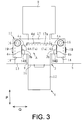
- the guide structure 30 comprises a guide-space delimiting part 15 that delimits a guide space A in communication with the attachment groove 3, and a regulation part 14B provided in the guide space A.
- the guide-space delimiting part 15 has a contact surface 14A that regulates a claw 4 in contact therewith at a position along the attachment groove 3 in a first direction P.
- the regulation part 14B regulates the claw 4 at a position along the attachment groove 3 in a second direction Q different from the first direction P.
- the first direction P corresponds to a direction along the chuck axis line CL
- the second direction Q corresponds to a direction perpendicular to the chuck axis line CL when seen in the radial direction.
- the second direction Q corresponds to the right and left direction in Fig. 3 .
- Such a guide structure 30 is described in more detail.
- an attachment surface 13 is formed on an outer surface of the chuck body 2 at a position corresponding to each attachment groove 3 (outer circumferential position of attachment groove 3).
- the attachment surface 13 has a flat shape.
- the guide-space delimiting part 15 is attached to the attachment surface 13 by bolts 16.
- the guide-space delimiting part 15 includes a rear part 17 positioned rearward of the guide space A, and a projecting part 18 projecting from the rear part 17 toward the front side of the chuck body 2.
- the rear part 17 extends in the second direction Q, and the projecting parts 18 project from both ends of the rear part 17 forward (downward in Fig. 3 ).
- the projecting parts 18 are positioned on both sides of the guide space A in the second direction Q.
- the rear part 17 and the projecting parts 18 delimit the guide space A.
- the rear part 17 of the guide-space delimiting part 15 has the aforementioned contact surfaces 14A (contact part) with which a guide surface 4a of the claw 4 is brought to be into contact.
- a position of the guide-space delimiting part 15 is adjusted such that the contact surface 14A is aligned with a bottom surface 7a of the bottom part 7 of the attachment groove 3.
- the projecting part 18 on each of the right and left sides has the regulation part 14B (contact part) with which a side surface 4b of the the claw 4 to be replaced is brought to be into contact.
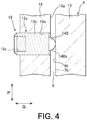
- the regulation part 14B is attached to the projecting part 18 through a regulation support part 19a.
- a set screw 19 which is illustrated as a combination of the regulation part 14B and the regulation support part 19a, for example, is attached to the projecting part 18.
- the regulation support part 19a is movably attached to the projecting part 18, and supports the regulation part 14B.
- the regulation support part 19a is a part of the set screw 19, which is other than the regulation part 14B.
- the regulation part 14B and the regulation support part 19a are integrally formed with each other.
- the regulation support part 19a is threadedly engaged with the projecting part 18.
- the regulation support part 19a includes a threaded part 19b to be threaded engaged with a screw hole 18a formed in the projecting part 18, and a tool fitting part 19c into which a tool (not shown) can be fitted.
- a tool can be inserted into the tool fitting part 19c from outside the guide-space delimiting part 15.
- a distal end part of the set screw 19 is formed as the regulation part 14B.
- the side surface 4b is brought into contact with the regulation part 14B.
- a distal end of the regulation part 14B is adjusted to be aligned with a side surface 7b of the bottom part 7 of the attachment groove 3 when seen in the radial direction.
- positions of the guide surfaces 4a and the side surfaces 4b of the claw 4 inserted in the guide space A can be aligned with the attachment groove 3 by the contact surface 14A and the regulation part 14B of the guide-space delimiting part 15.
- the guide-space delimiting part 15 may have a sidewall surface 15a that is positioned more outside in the guide space A (left side in Fig. 4 ) than the distal end of the regulation part 14B.
- the sidewall surface 15a delimits the guide space A.
- the sidewall surfaces 15a when seen in the radial direction, are formed on both sides (right and left sides in Fig. 3 ) of the guide space A.
- the sidewall surface 15a is positioned more outside (left side in Fig. 4 ) than the side surface 7b of the bottom part 7 of the attachment groove 3 in the second direction Q.
- a plurality of the aforementioned contact surfaces 14A may be provided on the rear part 17 of the guide-space delimiting part 15.
- two contact surfaces 14A are provided on the rear part 17, such that the contact surfaces 14A are located on both ends of the rear part 17 in the second direction Q.
- a rack recess 17a having a rearwardly recessed shape is provided between the two contact surfaces 14A.
- a rack 4d provided between the guide surfaces 4a of the claw 4 can be inserted into the rack recess 17a, so as to prevent the claw 4 from interfering with the guide-space delimiting part 15.
- a plurality of the regulation parts 14B may be provided in the guide space A at positions different form each other in the insertion direction of the claw 4 (radial direction).
- two set screws 19 each including the regulation part 14B are provided on the respective projecting parts 18.
- the two set screws 19 may be located at positions different from each other in a direction along the chuck axis line CL.
- the two set screws 19 each having the regulation part 14B may differ from each other in size.
- the regulation part 14B may have a curved surface 14Ba that is convex toward the inside of the guide space A.
- the curved surface 14Ba may be a part of a spherical surface.
- the side surface 4b of the claw 4 comes into contact with the curved surface 14Ba, so that a position of the side surface 4b is regulated.
- the claw 4 is first inserted into the guide space A of the aforementioned guide structure 30, so that the claw 4 is regulated by the regulation parts 14B to a position along the attachment groove 3 in the first direction P and the second direction Q.
- the claw 4 is lowered from a position above the guide space A to be inserted into the guide space A. Then, the guide surface 4a of the claw 4 comes into contact with the contact surface 14A of the rear part 17 of the guide-space delimiting part 15.
- the claw 4 is further lowered.
- the guide surface 4a of the claw 4 is located at a position along the bottom surface 7a of the bottom part 7 of the attachment groove 3 in the first direction P.
- the side surface 4b of the claw 4 comes into contact with the regulation part 14B of the set screw 19.
- the claw 4 is further lowered. In this manner, the side surface 4b of the claw 4 is located at a position along the side surface 7b of the bottom part 7 of the attachment groove 3 in the first direction P and the second direction Q.
- the claw 4 is moved from the guide space A to the attachment groove 3 so as to be inserted into the attachment groove 3.
- the claw 4 is lowered to a desired position in the attachment groove 3, with the guide surface 4a of the claw 4 being in contact with the contact surface 14A and the side surface 4b of the claw 4 being in contact with the regulation part 14B.
- the claw 4 of the chuck 1 can be inserted into the attachment groove 3 provided in the chuck body 2.
- the claw 4 inserted in the attachment groove 3 and the master jaw 9 are coupled by the locking mechanism (not shown) of the chuck body 2.
- the grasping claw 61 of the automatic claw replacement apparatus 60 is disengaged from the engagement recess 4c of the claw 4, and the grasping claw 61 is pulled up.
- the claw 4 of the chuck 1 is attached to the attachment groove 3 provided in the chuck body 2.
- the guide structure 30 may be attached to the attachment surface 13 of the chuck body 2 before the claw 4 may be inserted into the attachment groove 3 of the chuck body 2, and then the guide structure 30 may be detached from the attachment surface 13, after the claw 4 has been attached to the attachment groove 3.
- the chuck body 2 is provided with the guide-space delimiting part 15 having a plurality of the contact surfaces 14A and the regulation parts 14B with which the claw 4 to be replaced is brought to be into contact, the claw 4 can be moved toward the attachment groove 3 while the claw 4 is in contact with the contact surfaces 14A and the regulation parts 14B.
- a positioning plate and a chuck are distant from each other, it takes a long time to adjust the alignment of an attachment position of a jaw holder attached to the positioning plate and a jaw attachment groove of the chuck.
- positions of the guide surfaces 4a and the side surfaces 4b of the claw to be replaced can be quickly adapted to the attachment groove 3.
- the chuck body 2 with the guide-space delimiting part 15 eliminates the necessity of storing a component for guiding claw (jaw holder) in another place as in conventional case.
- the guide-space delimiting part 15 is attached to the chuck body 2 such that the contact surfaces 14A and the regulation parts 14B can be moved in accordance with the attachment groove 3.
- the movable set screw 19 is provided on the guide-space delimiting part 15, and the claw 4 in contact with the set screw 19 is moved toward the attachment groove 3.
- the claw 4 can be smoothly moved.
- the guide-space delimiting part 15, which delimits the guide space A in communication with the attachment groove 3 provided in the chuck body 2, has the contact surface 14A, and the regulation part 14B is provided in the guide space A.
- the contact surface 14A regulates the claw 4 at a position along the attachment groove 3 in the first direction P
- the regulation part 14B regulates the claw 4 at a position along the attachment groove 3 in the second direction Q.
- a plurality of the regulation parts 14B are provided in the guide space A at positions different from each other in the insertion direction of the claw 4.
- the claw 4 can be inserted from the guide space A into the attachment groove 3.
- the claw 4 to be replaced can be quickly moved toward the attachment groove 3.
- the regulation part 14B has the curved surface 14Ba that is convex toward the inside of the guide space A.
- the side surface 4b of the claw 4 can be easily regulated at a position along the side surface 7b of the attachment groove 3.
- the claw 4 to be replaced can be quickly moved toward the attachment groove 3.
- the guide-space delimiting part 15 has the sidewall surface 15a that is positioned more outside in the guide space A than the distal end of the regulation part 14B to delimit the guide space A.
- the side surface 4b of the claw 4 in the guide space A can be brought into contact with the regulation part 14B, whereby the side surface 4b of the claw 4 can be prevented from contacting the sidewall surface 15a.
- the side surface 4b of the claw 4 can be easily regulated at a position along the side surface 7b of the attachment groove 3, and the claw 4 to be replaced can be quickly moved toward the attachment groove 3.
- the guide-space delimiting part 15 has the regulation support part 19a which is movable and supports the regulation part 14B.
- the regulation support part 19a which is movable and supports the regulation part 14B.
- the regulation support part 19a is threadedly engaged with the guide-space delimiting part 15.
- the regulation support part 19a can be easily moved with respect to the guide-space delimiting part 15, and a position of the regulation part 14B can be easily adjusted to be along the side surface 7b of the attachment groove 3.
- the guide-space delimiting part 15 may be composed of the rear part 17 and one projecting part 18.
- the rear part 17 and this projecting part 18 define the guide space A for guiding a claw 4.
- the rear part 17 may be formed outside the rack 4d of the claw 4 (left side in Fig. 5 ).
- positions of the guide surfaces 4a and the side surfaces 4b of the claw 4 in the guide surface A can be adapted to the attachment groove 3 by the contact surface 14A and the regulation part 14B.
- the guide-space delimiting part 15 may be formed integrally with the chuck body 2.
- an outer circumferential portion of the attachment groove 3 in the chuck body 2 may serve as the guide-space delimiting part 15.
- the contact surface 14A adapted to the bottom surface 7a of the bottom part 7 of the attachment groove 3 is provided on the outer circumferential portion (upper part) of the attachment groove 3.
- the contact surface 14A may be formed continuously to the bottom surface 7a and/or may be coplanar with the bottom surface 7a.
- the regulation support part 19a of the set screw 19 having the regulation part 14B is threadedly engaged with the chuck body 2.
- positions of the guide surfaces 4a and the side surfaces 4b of the claw 4 in the guide surface A can be adapted to the attachment groove 3 by the contact surface 14A and the regulation part 14B.
- a modification example shown in Fig. 7 differs mainly from the modification example shown in Fig. 6 in that no set screw 19 is used.
- the regulation part 14B may be formed as an inclined surface formed by a typical chamfer process.
- the inclined surface may have a chamfer dimension of 2 mm at an angle of 45° with respect to the side surface 7b.
- the claw 4 in contact with the contact surface 14A which is similar to the contact surface 14A shown in Fig. 6 , is regulated by the contact surface 14A at a position along the attachment groove 3 in the first direction P.
- the claw 4 in contact with the regulation part 14B which is formed as the aforementioned inclined surface, is regulated by the regulation part 14B at a position along the attachment groove 3 in the second direction Q.
- the present invention is not limited to the aforementioned embodiment, and a part of the structure thereof can be suitably modified within a range not exceeding from the scope of the present invention.
Landscapes
- Engineering & Computer Science (AREA)
- Mechanical Engineering (AREA)
- Gripping On Spindles (AREA)
Applications Claiming Priority (2)
| Application Number | Priority Date | Filing Date | Title |
|---|---|---|---|
| JP2018203390 | 2018-10-30 | ||
| PCT/JP2019/042268 WO2020090780A1 (ja) | 2018-10-30 | 2019-10-29 | チャックの爪の案内構造およびチャックの爪の挿入方法 |
Publications (2)
| Publication Number | Publication Date |
|---|---|
| EP3875191A1 true EP3875191A1 (de) | 2021-09-08 |
| EP3875191A4 EP3875191A4 (de) | 2022-08-10 |
Family
ID=70463237
Family Applications (1)
| Application Number | Title | Priority Date | Filing Date |
|---|---|---|---|
| EP19877946.4A Pending EP3875191A4 (de) | 2018-10-30 | 2019-10-29 | Spannklauenführungsstruktur und spannklaueneinführungsverfahren |
Country Status (7)
| Country | Link |
|---|---|
| US (1) | US11992885B2 (de) |
| EP (1) | EP3875191A4 (de) |
| JP (1) | JP7068671B2 (de) |
| KR (1) | KR102529473B1 (de) |
| CN (1) | CN113056343B (de) |
| TW (1) | TWI737026B (de) |
| WO (1) | WO2020090780A1 (de) |
Family Cites Families (27)
| Publication number | Priority date | Publication date | Assignee | Title |
|---|---|---|---|---|
| DE656664C (de) | 1938-02-10 | Fritz Helfricht Fa | Auswechselbare, gehaertete und geschliffene Fuehrungsleisten fuer Spannfutterbacken | |
| DE612878C (de) * | 1935-05-07 | Forkardt Paul Kg | Backenfuehrung in Drehbankfuttern | |
| FR492961A (fr) * | 1917-12-10 | 1919-07-26 | Lodovico Boltri | Perfectionnements aux mandrins des machines-outils |
| US1401207A (en) * | 1920-02-18 | 1921-12-27 | Charles F Swissgabel | Chuck |
| US2920896A (en) | 1957-11-06 | 1960-01-12 | Buck Tool Co | Chuck jaw take-up, including a tapered gib |
| DE2104904C3 (de) * | 1971-02-03 | 1974-04-11 | Werkzeugmaschinenfabrik Gildemeister & Co Ag, 4800 Bielefeld | Spannvorrichtung für Drehmaschinen u.dgl. Werkzeugmaschinen mit Schnellwechsel der Aufsatzspannbacken |
| GB8327294D0 (en) | 1983-10-12 | 1983-11-16 | Pratt Int Ltd Burnerd | Jaw changing apparatus |
| DE3345012A1 (de) * | 1983-12-13 | 1985-06-20 | SMW Schneider & Weißhaupt GmbH, 7996 Meckenbeuren | Palette zur aufnahme von aufsatzspannbacken |
| JPS60249513A (ja) * | 1984-05-25 | 1985-12-10 | Howa Mach Ltd | チヤツク爪交換装置 |
| DE3501325A1 (de) * | 1985-01-17 | 1986-07-17 | SMW Schneider & Weißhaupt GmbH, 7996 Meckenbeuren | Spannfutter fuer werkzeugmaschinen |
| DE4029625C1 (de) * | 1990-09-19 | 1992-03-12 | Smw Schneider & Weisshaupt Gmbh, 7996 Meckenbeuren, De | |
| JP3185816B2 (ja) * | 1992-05-15 | 2001-07-11 | 豊和工業株式会社 | チャック爪自動交換装置 |
| US5845912A (en) * | 1996-05-07 | 1998-12-08 | Grupa; Robert J. | Adjustable quick change jaw apparatus |
| KR100641874B1 (ko) * | 2005-10-25 | 2006-11-10 | 주식회사 삼천리기계 | 소프트조우 퀵 체인지 척 |
| KR200405545Y1 (ko) * | 2005-10-26 | 2006-01-10 | 주식회사 삼천리기계 | 소프트조우 퀵 체인지 척 |
| FR2896713B1 (fr) * | 2006-02-02 | 2010-01-22 | Amyot Ets Sa | Mandrin porte-outil pour l'equipement d'une machine tournante |
| DE502006001824D1 (de) * | 2006-03-22 | 2008-11-27 | Smw Autoblok Spannsysteme Gmbh | Membranspannfutter |
| DE102006033396A1 (de) * | 2006-07-13 | 2008-01-17 | Hainbuch Gmbh Spannende Technik | Spannfutter und Verfahren zur Herstellung eines Spannfutters |
| CN103363461A (zh) * | 2012-03-30 | 2013-10-23 | 海洋王照明科技股份有限公司 | 手电筒及其灯筒 |
| KR101248997B1 (ko) * | 2012-08-13 | 2013-04-02 | 칸워크홀딩 주식회사 | 공작물 장착용 척 |
| JP6185293B2 (ja) | 2013-06-10 | 2017-08-23 | 株式会社北川鉄工所 | チャックのジョー自動交換装置 |
| EP2835197B1 (de) * | 2013-08-07 | 2015-12-02 | SMW-AUTOBLOK Spannsysteme GmbH | Spannfutter |
| CN203572407U (zh) * | 2013-11-14 | 2014-04-30 | 内蒙古第一机械集团有限公司 | 对表式弹性深度测量装置 |
| CN103817360B (zh) * | 2014-01-24 | 2016-08-17 | 华南理工大学 | 一种新型柔性四爪卡盘 |
| KR20150072321A (ko) * | 2014-08-20 | 2015-06-29 | 칸워크홀딩 주식회사 | 공작물 장착용 척 |
| CN204696574U (zh) * | 2015-06-12 | 2015-10-07 | 台州市路桥奇精剥线机制造厂 | 手拉剥线机 |
| EP3300821A4 (de) | 2016-05-16 | 2019-03-13 | Synthe Tech Inc. | Spannfutter, abgestufte backe und werkzeugmaschine |
-
2019
- 2019-10-29 US US17/290,622 patent/US11992885B2/en active Active
- 2019-10-29 KR KR1020217011565A patent/KR102529473B1/ko active Active
- 2019-10-29 CN CN201980071906.3A patent/CN113056343B/zh active Active
- 2019-10-29 TW TW108139110A patent/TWI737026B/zh active
- 2019-10-29 EP EP19877946.4A patent/EP3875191A4/de active Pending
- 2019-10-29 JP JP2020553917A patent/JP7068671B2/ja active Active
- 2019-10-29 WO PCT/JP2019/042268 patent/WO2020090780A1/ja not_active Ceased
Also Published As
| Publication number | Publication date |
|---|---|
| TWI737026B (zh) | 2021-08-21 |
| KR102529473B1 (ko) | 2023-05-04 |
| TW202026075A (zh) | 2020-07-16 |
| JPWO2020090780A1 (ja) | 2021-09-02 |
| EP3875191A4 (de) | 2022-08-10 |
| JP7068671B2 (ja) | 2022-05-17 |
| US11992885B2 (en) | 2024-05-28 |
| US20210379674A1 (en) | 2021-12-09 |
| CN113056343B (zh) | 2024-10-01 |
| CN113056343A (zh) | 2021-06-29 |
| KR20210053997A (ko) | 2021-05-12 |
| WO2020090780A1 (ja) | 2020-05-07 |
Similar Documents
| Publication | Publication Date | Title |
|---|---|---|
| US8464618B2 (en) | Numerically controlled lathe with guide bush, and method of processing workpiece by using the numerically controlled lathe | |
| KR200437457Y1 (ko) | 정밀부품 가공용 씨엔씨 선반 척죠오 | |
| US8573100B2 (en) | Loading magazine with moveable channel system for loading and unloading automatic lathes | |
| KR20160106416A (ko) | 공작기계용 공작물 길이조절구조 | |
| US4431202A (en) | Pivoted jaw members | |
| US20150273591A1 (en) | Boring tool | |
| KR20160072390A (ko) | 미세조절이 가능한 공작기계용 척 | |
| US2777704A (en) | Precision chuck jaws | |
| US2158490A (en) | Automatic chuck jaw | |
| US11945035B2 (en) | Tool holder | |
| US11992885B2 (en) | Chuck-claw guide structure and chuck-claw insertion method | |
| US11478861B2 (en) | Chuck-claw coupling mechanism | |
| US9138810B2 (en) | Work supply apparatus and machine tool provided with the work supply apparatus | |
| CN109014266A (zh) | 一种机床应用的新型卡盘结构 | |
| KR102126124B1 (ko) | 라이브 센터 인출 기능을 갖는 공작기계용 심압대 | |
| US20250205787A1 (en) | Guide bush apparatus and adjustment method for guide bush apparatus | |
| KR20200002225U (ko) | 센터 드릴 위치 조정 홀더 | |
| JP4331937B2 (ja) | 棒材供給機 | |
| US20250170657A1 (en) | Method for machining a workpiece and adapter for use when machining a workpiece | |
| KR20110078328A (ko) | 선반용 공구대 | |
| JP2009078355A (ja) | ワーク供給装置 | |
| JP2016049611A (ja) | 工具ホルダと主軸の締結構造 | |
| JP5211627B2 (ja) | 切削工具 | |
| US2775167A (en) | Machining of long work-pieces | |
| JPH10309628A (ja) | ねじ切り用治具 |
Legal Events
| Date | Code | Title | Description |
|---|---|---|---|
| STAA | Information on the status of an ep patent application or granted ep patent |
Free format text: STATUS: THE INTERNATIONAL PUBLICATION HAS BEEN MADE |
|
| PUAI | Public reference made under article 153(3) epc to a published international application that has entered the european phase |
Free format text: ORIGINAL CODE: 0009012 |
|
| STAA | Information on the status of an ep patent application or granted ep patent |
Free format text: STATUS: REQUEST FOR EXAMINATION WAS MADE |
|
| 17P | Request for examination filed |
Effective date: 20210517 |
|
| AK | Designated contracting states |
Kind code of ref document: A1 Designated state(s): AL AT BE BG CH CY CZ DE DK EE ES FI FR GB GR HR HU IE IS IT LI LT LU LV MC MK MT NL NO PL PT RO RS SE SI SK SM TR |
|
| DAV | Request for validation of the european patent (deleted) | ||
| DAX | Request for extension of the european patent (deleted) | ||
| A4 | Supplementary search report drawn up and despatched |
Effective date: 20220711 |
|
| RIC1 | Information provided on ipc code assigned before grant |
Ipc: B23B 31/10 20060101ALI20220705BHEP Ipc: B23B 31/39 20060101ALI20220705BHEP Ipc: B23B 31/16 20060101AFI20220705BHEP |