EP3876384A1 - Bloc-batterie et son procédé de gestion de charge - Google Patents
Bloc-batterie et son procédé de gestion de charge Download PDFInfo
- Publication number
- EP3876384A1 EP3876384A1 EP21158851.2A EP21158851A EP3876384A1 EP 3876384 A1 EP3876384 A1 EP 3876384A1 EP 21158851 A EP21158851 A EP 21158851A EP 3876384 A1 EP3876384 A1 EP 3876384A1
- Authority
- EP
- European Patent Office
- Prior art keywords
- cell
- cells
- electromotive force
- battery pack
- charging
- Prior art date
- Legal status (The legal status is an assumption and is not a legal conclusion. Google has not performed a legal analysis and makes no representation as to the accuracy of the status listed.)
- Withdrawn
Links
Images
Classifications
-
- H—ELECTRICITY
- H01—ELECTRIC ELEMENTS
- H01M—PROCESSES OR MEANS, e.g. BATTERIES, FOR THE DIRECT CONVERSION OF CHEMICAL ENERGY INTO ELECTRICAL ENERGY
- H01M10/00—Secondary cells; Manufacture thereof
- H01M10/42—Methods or arrangements for servicing or maintenance of secondary cells or secondary half-cells
- H01M10/4207—Methods or arrangements for servicing or maintenance of secondary cells or secondary half-cells for several batteries or cells simultaneously or sequentially
-
- H—ELECTRICITY
- H02—GENERATION; CONVERSION OR DISTRIBUTION OF ELECTRIC POWER
- H02J—ELECTRIC POWER NETWORKS; CIRCUIT ARRANGEMENTS OR SYSTEMS FOR SUPPLYING OR DISTRIBUTING ELECTRIC POWER; SYSTEMS FOR STORING ELECTRIC ENERGY
- H02J7/00—Circuit arrangements for charging or discharging batteries or for supplying loads from batteries
- H02J7/50—Circuit arrangements for charging or discharging batteries or for supplying loads from batteries acting upon multiple batteries simultaneously or sequentially
- H02J7/52—Circuit arrangements for charging or discharging batteries or for supplying loads from batteries acting upon multiple batteries simultaneously or sequentially for charge balancing, e.g. equalisation of charge between batteries
- H02J7/54—Passive balancing, e.g. using resistors or parallel MOSFETs
-
- H—ELECTRICITY
- H02—GENERATION; CONVERSION OR DISTRIBUTION OF ELECTRIC POWER
- H02J—ELECTRIC POWER NETWORKS; CIRCUIT ARRANGEMENTS OR SYSTEMS FOR SUPPLYING OR DISTRIBUTING ELECTRIC POWER; SYSTEMS FOR STORING ELECTRIC ENERGY
- H02J7/00—Circuit arrangements for charging or discharging batteries or for supplying loads from batteries
- H02J7/50—Circuit arrangements for charging or discharging batteries or for supplying loads from batteries acting upon multiple batteries simultaneously or sequentially
- H02J7/52—Circuit arrangements for charging or discharging batteries or for supplying loads from batteries acting upon multiple batteries simultaneously or sequentially for charge balancing, e.g. equalisation of charge between batteries
-
- G—PHYSICS
- G01—MEASURING; TESTING
- G01R—MEASURING ELECTRIC VARIABLES; MEASURING MAGNETIC VARIABLES
- G01R27/00—Arrangements for measuring resistance, reactance, impedance, or electric characteristics derived therefrom
- G01R27/02—Measuring real or complex resistance, reactance, impedance, or other two-pole characteristics derived therefrom, e.g. time constant
- G01R27/08—Measuring resistance by measuring both voltage and current
-
- G—PHYSICS
- G01—MEASURING; TESTING
- G01R—MEASURING ELECTRIC VARIABLES; MEASURING MAGNETIC VARIABLES
- G01R31/00—Arrangements for testing electric properties; Arrangements for locating electric faults; Arrangements for electrical testing characterised by what is being tested not provided for elsewhere
- G01R31/36—Arrangements for testing, measuring or monitoring the electrical condition of accumulators or electric batteries, e.g. capacity or state of charge [SoC]
- G01R31/389—Measuring internal impedance, internal conductance or related variables
-
- H—ELECTRICITY
- H01—ELECTRIC ELEMENTS
- H01M—PROCESSES OR MEANS, e.g. BATTERIES, FOR THE DIRECT CONVERSION OF CHEMICAL ENERGY INTO ELECTRICAL ENERGY
- H01M10/00—Secondary cells; Manufacture thereof
- H01M10/42—Methods or arrangements for servicing or maintenance of secondary cells or secondary half-cells
- H01M10/425—Structural combination with electronic components, e.g. electronic circuits integrated to the outside of the casing
- H01M10/4257—Smart batteries, e.g. electronic circuits inside the housing of the cells or batteries
-
- H—ELECTRICITY
- H01—ELECTRIC ELEMENTS
- H01M—PROCESSES OR MEANS, e.g. BATTERIES, FOR THE DIRECT CONVERSION OF CHEMICAL ENERGY INTO ELECTRICAL ENERGY
- H01M10/00—Secondary cells; Manufacture thereof
- H01M10/42—Methods or arrangements for servicing or maintenance of secondary cells or secondary half-cells
- H01M10/44—Methods for charging or discharging
- H01M10/441—Methods for charging or discharging for several batteries or cells simultaneously or sequentially
-
- H—ELECTRICITY
- H02—GENERATION; CONVERSION OR DISTRIBUTION OF ELECTRIC POWER
- H02J—ELECTRIC POWER NETWORKS; CIRCUIT ARRANGEMENTS OR SYSTEMS FOR SUPPLYING OR DISTRIBUTING ELECTRIC POWER; SYSTEMS FOR STORING ELECTRIC ENERGY
- H02J7/00—Circuit arrangements for charging or discharging batteries or for supplying loads from batteries
- H02J7/50—Circuit arrangements for charging or discharging batteries or for supplying loads from batteries acting upon multiple batteries simultaneously or sequentially
- H02J7/575—Parallel/serial switching of connection of batteries to charge or load circuit
-
- H—ELECTRICITY
- H02—GENERATION; CONVERSION OR DISTRIBUTION OF ELECTRIC POWER
- H02J—ELECTRIC POWER NETWORKS; CIRCUIT ARRANGEMENTS OR SYSTEMS FOR SUPPLYING OR DISTRIBUTING ELECTRIC POWER; SYSTEMS FOR STORING ELECTRIC ENERGY
- H02J7/00—Circuit arrangements for charging or discharging batteries or for supplying loads from batteries
- H02J7/80—Circuit arrangements for charging or discharging batteries or for supplying loads from batteries including monitoring or indicating arrangements
-
- H—ELECTRICITY
- H02—GENERATION; CONVERSION OR DISTRIBUTION OF ELECTRIC POWER
- H02J—ELECTRIC POWER NETWORKS; CIRCUIT ARRANGEMENTS OR SYSTEMS FOR SUPPLYING OR DISTRIBUTING ELECTRIC POWER; SYSTEMS FOR STORING ELECTRIC ENERGY
- H02J7/00—Circuit arrangements for charging or discharging batteries or for supplying loads from batteries
- H02J7/90—Regulation of charging or discharging current or voltage
-
- H—ELECTRICITY
- H01—ELECTRIC ELEMENTS
- H01M—PROCESSES OR MEANS, e.g. BATTERIES, FOR THE DIRECT CONVERSION OF CHEMICAL ENERGY INTO ELECTRICAL ENERGY
- H01M10/00—Secondary cells; Manufacture thereof
- H01M10/42—Methods or arrangements for servicing or maintenance of secondary cells or secondary half-cells
- H01M10/425—Structural combination with electronic components, e.g. electronic circuits integrated to the outside of the casing
- H01M2010/4271—Battery management systems including electronic circuits, e.g. control of current or voltage to keep battery in healthy state, cell balancing
-
- Y—GENERAL TAGGING OF NEW TECHNOLOGICAL DEVELOPMENTS; GENERAL TAGGING OF CROSS-SECTIONAL TECHNOLOGIES SPANNING OVER SEVERAL SECTIONS OF THE IPC; TECHNICAL SUBJECTS COVERED BY FORMER USPC CROSS-REFERENCE ART COLLECTIONS [XRACs] AND DIGESTS
- Y02—TECHNOLOGIES OR APPLICATIONS FOR MITIGATION OR ADAPTATION AGAINST CLIMATE CHANGE
- Y02E—REDUCTION OF GREENHOUSE GAS [GHG] EMISSIONS, RELATED TO ENERGY GENERATION, TRANSMISSION OR DISTRIBUTION
- Y02E60/00—Enabling technologies; Technologies with a potential or indirect contribution to GHG emissions mitigation
- Y02E60/10—Energy storage using batteries
Definitions
- the current mainstream balancing method for a battery pack is to detect a terminal voltage of a single cell and determine a cell to be balanced according to a difference between terminal voltages of cells in a cell charging process.
- This balancing method has the following disadvantage: after the battery pack is used for a long time, a difference in internal resistance between cells increases; in the cell charging process, the difference in internal resistance causes a difference between the terminal voltages of the cells so that an error may exist when balancing determination is directly performed according to the terminal voltages of the cells, that is, the cell needs to be balanced is determined incorrectly, which reduces the accuracy and reliability of balanced charging.
- an embodiment of the present invention further provides a battery pack.
- the battery pack includes a housing and a cell group and a control module that are disposed in the housing.
- the cell group is configured to output a power signal.
- the control module is configured to acquire internal resistance of each cell in the battery pack; acquire a terminal voltage of the each cell in real time in a case where cells are charged with a constant current; determine an electromotive force of the each cell based on the internal resistance of the each cell and a charging current and the terminal voltage in the case where the cells are charged with the constant current; determine a target cell from the cells based on the electromotive force of the each cell; and perform charging balancing management on the target cell.
- an embodiment of the present invention provides a charging management method. The method includes steps described below.
- a terminal voltage of the each cell is acquired in real time in a case where cells are charged with a constant current.
- An electromotive force of the each cell is determined based on the internal resistance of the each cell and a charging current and the terminal voltage in the case where the cells are charged with the constant current.
- a target cell is determined from the cells based on the electromotive force of the each cell.
- Charging balancing management is performed on the target cell.
- Embodiments of the present invention provide a battery pack.
- the battery pack may be typically applied to an electric power tool such as an angle grinder.
- the electric power tool is provided with a battery pack coupling part, and the battery pack is coupled to the electric power tool through the battery pack coupling part so that the electric power tool is powered by the battery pack.
- the voltage of the battery pack is generally 10.8 V, 24 V, 36 V, 48 V, 56 V, or 80 V, which is not limited herein.
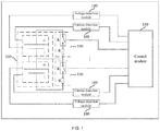
- FIG. 1 is a block diagram of a battery pack according to an embodiment of the present invention.
- the battery pack 10 includes a housing (not shown in the figure) and a cell group 110 and a control module 120 that are disposed in the housing.
- the cell group 110 is disposed in the accommodation space formed by the housing and is configured to output a power signal. Specifically, the cell group is configured to output electric energy to make the electric power tool operate.
- the cell group 110 further includes multiple cells.
- the control module is configured to: acquire internal resistance of each cell in the battery pack; acquire a terminal voltage of each cell in real time in the case where the cells are charged with a constant current; determine an electromotive force of each cell based on the internal resistance of each cell and a charging current and the terminal voltage in the case where the cells are charged with the constant current; determine a target cell from the multiple cells based on the electromotive force of each cell; and perform charging balancing management on the target cell.
- control module 120 is specifically configured to perform operations described below.
- Charging is stopped in the case where the current power reaches the power threshold.
- a voltage variation of each cell is acquired.
- the internal resistance of each cell is determined based on the voltage variation and the charging current.
- control module 120 is specifically configured to perform operations described below.
- a minimum electromotive force is determined based on the electromotive force of each cell.
- a cell whose electromotive force has a difference greater than a set voltage threshold than the minimum electromotive force is determined as the target cell.
- control module 120 is specifically configured to perform an operation described below.
- the target cell is discharged until a difference between an electromotive force of the target cell and the minimum electromotive force is less than or equal to the set voltage threshold.
- control module 120 is specifically configured to perform an operation described below.
- a discharge circuit is controlled to be connected to two ends of the target cell, where the discharge circuit includes a discharge resistor.
- the battery pack 10 further includes multiple voltage detection modules 130 and multiple current detection modules 140.
- the control module is connected to the cells through voltage detection circuits and current detection circuits so that the control module can acquire the terminal voltage and the charging current.
- each cell is connected to the control module through one voltage detection module 130, and the control module detects the voltage of the corresponding cell through the voltage detection module 130.
- Each cell is connected to the control module through one current detection module 140, and the control module detects the charging current of the corresponding cell through the current detection module 140.
- the battery pack further includes multiple discharge circuits 150 that are connected in correspondence to the cells.
- One end of each discharge circuit 150 is connected to a positive electrode of its respective cell, and the other end of each discharge circuit 150 is connected to a negative electrode of its respective cell.
- Each discharge circuit 150 includes a controllable switch and a resistor that are arranged in series. A control end of the controllable switch is connected to the control module. Each discharge circuit 150 is configured to control its respective cell to be discharged in response to the control module so that the control module can control the corresponding discharge circuit 150 to turn on or off through the controllable switch and perform the charging balancing management on the target cell according to a charging management strategy described below.
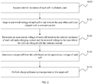
- FIG. 2 is a flowchart of a charging management method according to an embodiment of the present invention.
- This embodiment may be applied to balance the charging of a battery pack. For example, in the process of charging the battery pack, each cell in the battery pack is balanced and managed, so as to improve the accuracy and reliability of the balanced charging of each cell in the battery pack.
- This method may be performed by a charging management device such as the control module.
- the charging management method specifically includes steps described below.
- the battery pack includes multiple cells. Charging the battery pack means charging each cell in the battery pack. After the battery pack is used for a long time, a difference in internal resistance between cells is relatively large. Therefore, the internal resistance of each cell is acquired so that a voltage drop of the internal resistance of each cell can be determined and then an electromotive force of each cell can be determined based on the voltage drop of the internal resistance of each cell.
- the step of acquiring the internal resistance of each cell specifically includes steps described below.
- Charging is stopped in the case where the current power reaches the power threshold.
- a voltage variation of each cell is acquired.
- the internal resistance of each cell is determined based on the voltage variation and a charging current.
- the power of the battery pack may be represented by a state of charge (SoC).
- SoC state of charge
- the value of the SoC represents the ratio of the remaining power of a battery to a capacity of the battery and is expressed as a percentage.
- the power threshold of the battery pack may be selected based on whether an actual charging current is stable. For example, in the case where the charging current for charging the battery pack becomes stable, the power of the battery pack is 5%. Then the power threshold of the battery pack may be selected to be greater than or equal to 5%.
- the battery pack is charged with a constant current, so the current power of the battery pack may be calculated based on charging time and the charging current, where the charging current may be detected by configuring a current detection circuit.
- the charging is stopped.
- the battery pack is in an open-circuit state, so the acquired voltage of each cell is an open-circuit voltage of each cell, that is, the electromotive force.
- a terminal voltage of each cell includes the voltage drop of the internal resistance of the cell and the electromotive force of the cell. Therefore, the electromotive force of each cell and the terminal voltage of each cell when it is charged are acquired so that the voltage variation corresponding to each cell may be acquired, where the voltage variation is the voltage drop of the internal resistance of each cell. Based on the charging current and the obtained voltage variation, the internal resistance of each cell may be calculated.
- the internal resistance of each cell only needs to be calculated once, the calculated internal resistance of each cell is used for calculating the voltage drop of the internal resistance of each cell in the subsequent charging process, and then the electromotive force of each cell is calculated.
- the terminal voltage of each cell is acquired in real time in the case where each cell is charged with the constant current.
- the terminal voltage of the cell refers to the voltage between the positive and negative electrodes of the cell.
- one voltage detection circuit is connected to two ends of each cell so that the terminal voltage of each cell may be acquired in real time.
- the electromotive force of each cell is determined based on the internal resistance of each cell and the charging current and the terminal voltage in the case where each cell is charged with the constant current.
- the terminal voltage of each cell under this operating condition includes the voltage drop of the internal resistance of the cell and the electromotive force of the cell.
- the internal resistance of the cell is multiplied by the charging current at this time so that the voltage drop of the internal resistance is obtained and then the voltage drop of the internal resistance of the cell is subtracted from the terminal voltage of the cell so that the electromotive force of the cell is obtained.
- the electromotive force of the cell is the voltage obtained after the voltage drop of the internal resistance of the cell is subtracted and thus truly reflects the effective voltage of the cell. Therefore, charging balancing management is performed on each cell based on the electromotive force of each cell, which can improve the accuracy and reliability of balanced charging.
- a target cell is determined from cells based on the electromotive force of each cell.
- the target cell is the cell to be balanced. Since the electromotive force of the cell truly reflects the effective voltage of the cell, the cell to be balanced, that is, the target cell, may be determined through the comparison of a voltage difference between the electromotive forces of the cells.
- the step of determining the target cell specifically includes steps described below.
- a minimum electromotive force is determined based on the electromotive force of each cell.
- a cell whose electromotive force has a difference greater than a set voltage threshold than the minimum electromotive force is determined as the target cell.
- the minimum electromotive force is determined through the comparison of the electromotive forces of the cells. In the case where a difference between the electromotive force of a certain cell and the minimum electromotive force exceeds the set voltage threshold, the cell is determined as the target cell. Further, in the case where differences between the electromotive forces of multiple cells and the minimum electromotive force are greater than the set voltage threshold, the multiple cells are all determined as the target cells. Accordingly, the charging balancing management is performed on the multiple target cells.
- the process of determining the target cell is a continuous process, that is, in the process of charging the battery pack, the target cell at a current charging stage is continuously determined according to the preceding method so that the determined target cell is balanced and managed in real time.
- the charging balancing management is performed on the target cell.
- Performing the charging balancing management on the target cell refers to discharging the target cell to adjust the electromotive force of the target cell until the difference between the electromotive force of the target cell and the minimum electromotive force is less than or equal to the set voltage threshold.
- a discharge circuit is connected to two ends of each cell. Accordingly, the step of discharging the target cell specifically includes a step described below.
- the discharge circuit is controlled to be connected to two ends of the target cell, where the discharge circuit includes a discharge resistor.
- the discharge circuit is connected to two ends of each cell, and the discharge circuit may include a controllable switch and the discharge resistor. In the case where the controllable switch is turned off, the discharge circuit is disconnected from the corresponding cell and the discharge circuit does not function. In the case where the controllable switch is turned on, the discharge circuit communicates with the corresponding cell so that the cell is discharged through the discharge resistor. In this manner, the electromotive force of the target cell is adjusted such that the difference between the electromotive force of the target cell and the minimum electromotive force does not exceed the set voltage threshold.
- the resistance of the discharge resistor is within a range of 10 K to 100 K so that the cell is slowly discharged with a small discharging current. In this manner, the following case can be avoided: the electromotive force of the cell is too small due to too large a discharging current and so the cell enters an unbalanced state again.
- the target cell is determined based on the electromotive force of each cell and then the electromotive force of the target cell is adjusted by discharging the target cell so that the charging balancing management is performed on the target cell and the accuracy of the charging balancing management performed on the battery pack is improved.
- the principle of the charging balancing management is as follows: in the process of charging the battery pack, the internal resistance of each cell in the battery pack is detected, the voltage drop of the internal resistance of each cell is calculated from the internal resistance, and the electromotive force of each cell is obtained so that the charging balancing management is performed on each cell based on the electromotive force of each cell.
- the internal resistance of each cell in the battery pack is acquired, the voltage drop of the internal resistance of each cell in the charging process is calculated, and then the terminal voltage of each cell is acquired so that the electromotive force of each cell is calculated; the terminal voltage of each cell is acquired in real time and the electromotive force of each cell may be calculated in real time so that the cell to be balanced and managed is determined based on the electromotive force of each cell and then the cell is balanced and managed.
- the electromotive force of each cell calculated in this embodiment is the effective voltage of the cell obtained after the voltage drop of the internal resistance of the cell is subtracted. Therefore, the electromotive force of each cell can truly reflect the current voltage state of each cell. In this manner, the charging balancing management is performed on each cell based on the electromotive force so that the cell to be balanced and managed can be accurately determined and then the charging balancing management is performed on the cell, thereby improving the accuracy and reliability of the balanced charging.
Landscapes
- Engineering & Computer Science (AREA)
- Power Engineering (AREA)
- Physics & Mathematics (AREA)
- General Physics & Mathematics (AREA)
- Manufacturing & Machinery (AREA)
- Chemical & Material Sciences (AREA)
- Chemical Kinetics & Catalysis (AREA)
- Electrochemistry (AREA)
- General Chemical & Material Sciences (AREA)
- Microelectronics & Electronic Packaging (AREA)
- Charge And Discharge Circuits For Batteries Or The Like (AREA)
- Secondary Cells (AREA)
Applications Claiming Priority (1)
| Application Number | Priority Date | Filing Date | Title |
|---|---|---|---|
| CN202010143720.9A CN113364068A (zh) | 2020-03-04 | 2020-03-04 | 充电管理方法和电池包 |
Publications (1)
| Publication Number | Publication Date |
|---|---|
| EP3876384A1 true EP3876384A1 (fr) | 2021-09-08 |
Family
ID=74732693
Family Applications (1)
| Application Number | Title | Priority Date | Filing Date |
|---|---|---|---|
| EP21158851.2A Withdrawn EP3876384A1 (fr) | 2020-03-04 | 2021-02-24 | Bloc-batterie et son procédé de gestion de charge |
Country Status (3)
| Country | Link |
|---|---|
| US (1) | US11705740B2 (fr) |
| EP (1) | EP3876384A1 (fr) |
| CN (1) | CN113364068A (fr) |
Cited By (1)
| Publication number | Priority date | Publication date | Assignee | Title |
|---|---|---|---|---|
| US11495976B2 (en) * | 2019-10-01 | 2022-11-08 | Samsung Sdi Co., Ltd. | Battery system and method for controlling battery system |
Families Citing this family (3)
| Publication number | Priority date | Publication date | Assignee | Title |
|---|---|---|---|---|
| CN112952224B (zh) * | 2019-12-11 | 2022-12-20 | 南京泉峰科技有限公司 | 一种电池包的充电平衡方法、系统和电池包 |
| KR20220057368A (ko) * | 2020-10-29 | 2022-05-09 | 주식회사 엘지에너지솔루션 | 배터리 관리 장치 및 방법, 배터리 관리 시스템 |
| CN114614116B (zh) * | 2022-02-28 | 2023-06-27 | 福建星云电子股份有限公司 | 一种电芯动态均衡修复方法 |
Citations (5)
| Publication number | Priority date | Publication date | Assignee | Title |
|---|---|---|---|---|
| US20130088201A1 (en) * | 2010-04-23 | 2013-04-11 | Hitachi, Ltd. | Battery pack and battery pack controller |
| US20130187608A1 (en) * | 2012-01-20 | 2013-07-25 | Via Technologies, Inc. | Rechargeable battery module and battery charging method |
| US20140361743A1 (en) * | 2013-06-11 | 2014-12-11 | Ford Global Technologies, Llc | Detection of Imbalance Across Multiple Battery Cells Measured by the Same Voltage Sensor |
| US20170113564A1 (en) * | 2015-10-27 | 2017-04-27 | Honda Motor Co., Ltd. | Energy storage apparatus, vehicle apparatus, and control method |
| US20170264123A1 (en) * | 2016-03-09 | 2017-09-14 | Servato Corporation | Battery management system and related techniques for adaptive, dynamic control of battery charging |
Family Cites Families (22)
| Publication number | Priority date | Publication date | Assignee | Title |
|---|---|---|---|---|
| JP2004301782A (ja) * | 2003-03-31 | 2004-10-28 | Yazaki Corp | 満充電状態検出装置及びその方法、充電状態検出装置及びその方法、劣化度検出装置及びその方法 |
| JP4547908B2 (ja) * | 2003-12-25 | 2010-09-22 | 日産自動車株式会社 | 二次電池の入出力可能電力推定装置 |
| KR101156977B1 (ko) * | 2007-12-31 | 2012-06-20 | 에스케이이노베이션 주식회사 | 고전압 배터리 팩의 셀 밸런싱 방법 |
| JP2011200095A (ja) * | 2010-02-26 | 2011-10-06 | Sanyo Electric Co Ltd | 電池システム |
| KR101256079B1 (ko) * | 2010-12-28 | 2013-04-19 | 삼성에스디아이 주식회사 | 배터리 팩의 밸런싱 방법 및 밸런싱 시스템 |
| US20120274283A1 (en) * | 2011-04-28 | 2012-11-01 | Van Lammeren Johannes | Battery cell-balancing method and apparatus |
| WO2013054672A1 (fr) * | 2011-10-11 | 2013-04-18 | 新神戸電機株式会社 | Système d'accumulateur au plomb |
| CN103515658B (zh) * | 2012-06-29 | 2016-10-05 | 联想(北京)有限公司 | 充电电池单元以及充电管理方法 |
| WO2014167644A1 (fr) * | 2013-04-09 | 2014-10-16 | 三菱電機株式会社 | Appareil de détection de défaillance d'un capteur de tension |
| CN104852414B (zh) * | 2014-02-19 | 2018-06-19 | 东莞钜威动力技术有限公司 | 一种电池组电芯的均衡方法及装置 |
| CN104505550B (zh) * | 2014-12-25 | 2017-01-18 | 宁德时代新能源科技股份有限公司 | 磷酸铁锂电池组的被动均衡方法及系统 |
| DE102015212328B4 (de) * | 2015-07-01 | 2019-03-21 | Dialog Semiconductor (Uk) Limited | Batterieladezustandsmessschaltung |
| CN105759221A (zh) * | 2016-04-29 | 2016-07-13 | 赵建和 | 一种带有内阻监测功能的动力电池组管理系统 |
| CN107819336A (zh) * | 2016-09-13 | 2018-03-20 | 成都天府新区光启未来技术研究院 | 锂电池的均衡方法、装置和系统 |
| CN107492917B (zh) * | 2016-09-28 | 2019-11-22 | 宝沃汽车(中国)有限公司 | 动力电池的电量均衡方法、电池管理系统及动力电车 |
| JP6967731B2 (ja) * | 2017-01-16 | 2021-11-17 | パナソニックIpマネジメント株式会社 | 検査装置、検査方法、検査プログラム、管理装置、及び蓄電システム |
| KR101850295B1 (ko) * | 2017-03-08 | 2018-04-19 | (주)아이비티 | 블루투스 통신 기반 사물인터넷을 이용한 밸런싱 전류 가변 배터리 팩 균등 충전 장치 |
| KR102533201B1 (ko) * | 2018-06-12 | 2023-05-15 | 삼성에스디아이 주식회사 | 전압 평형 장치 |
| WO2020022463A1 (fr) * | 2018-07-27 | 2020-01-30 | 株式会社Gsユアサ | Dispositif de stockage électrique et procédé d'estimation de température |
| CN112514196A (zh) * | 2018-07-31 | 2021-03-16 | 赛昂能源有限公司 | 多路复用的充放电电池管理系统 |
| US10897143B2 (en) * | 2018-08-22 | 2021-01-19 | Texas Instruments Incorporated | Passive cell-balancing with dynamic charge control |
| EP3846278B1 (fr) * | 2018-08-29 | 2025-03-19 | Nuvoton Technology Corporation Japan | Circuit de surveillance de cellule et système de gestion |
-
2020
- 2020-03-04 CN CN202010143720.9A patent/CN113364068A/zh active Pending
-
2021
- 2021-02-22 US US17/181,030 patent/US11705740B2/en active Active
- 2021-02-24 EP EP21158851.2A patent/EP3876384A1/fr not_active Withdrawn
Patent Citations (5)
| Publication number | Priority date | Publication date | Assignee | Title |
|---|---|---|---|---|
| US20130088201A1 (en) * | 2010-04-23 | 2013-04-11 | Hitachi, Ltd. | Battery pack and battery pack controller |
| US20130187608A1 (en) * | 2012-01-20 | 2013-07-25 | Via Technologies, Inc. | Rechargeable battery module and battery charging method |
| US20140361743A1 (en) * | 2013-06-11 | 2014-12-11 | Ford Global Technologies, Llc | Detection of Imbalance Across Multiple Battery Cells Measured by the Same Voltage Sensor |
| US20170113564A1 (en) * | 2015-10-27 | 2017-04-27 | Honda Motor Co., Ltd. | Energy storage apparatus, vehicle apparatus, and control method |
| US20170264123A1 (en) * | 2016-03-09 | 2017-09-14 | Servato Corporation | Battery management system and related techniques for adaptive, dynamic control of battery charging |
Cited By (1)
| Publication number | Priority date | Publication date | Assignee | Title |
|---|---|---|---|---|
| US11495976B2 (en) * | 2019-10-01 | 2022-11-08 | Samsung Sdi Co., Ltd. | Battery system and method for controlling battery system |
Also Published As
| Publication number | Publication date |
|---|---|
| US11705740B2 (en) | 2023-07-18 |
| US20210281083A1 (en) | 2021-09-09 |
| CN113364068A (zh) | 2021-09-07 |
Similar Documents
| Publication | Publication Date | Title |
|---|---|---|
| EP3876384A1 (fr) | Bloc-batterie et son procédé de gestion de charge | |
| EP3958006B1 (fr) | Appareil et procédé de diagnostic de batterie | |
| US11456610B2 (en) | Internal short sensing battery control apparatus and battery control method | |
| JP5104416B2 (ja) | 組電池の異常検出装置 | |
| US20120161709A1 (en) | Secondary-battery control apparatus | |
| JPH04372536A (ja) | 蓄電池を使用した電子機器 | |
| EP3006946B1 (fr) | Dispositif de surveillance de batterie de stockage | |
| CN115885402B (zh) | 用于对氧化还原液流电池系统进行状态监控的方法 | |
| EP3828565B1 (fr) | Véhicule et son procédé de commande | |
| US11714140B2 (en) | Ground fault detection device | |
| JP3797254B2 (ja) | 二次電池の容量調整方式 | |
| KR20200135046A (ko) | 셀 밸런싱 방법 및 이를 적용한 배터리 관리 시스템 | |
| CN108333516B (zh) | 电池状态测试方法及其系统 | |
| EP1918728A1 (fr) | Techniques de diagnostic et de prévision de batterie au lithium ion | |
| JP6478293B2 (ja) | 電池管理ユニット及びその制御方法 | |
| JPH0915311A (ja) | 組電池の故障検出装置 | |
| US20240405299A1 (en) | Battery control device and battery control method | |
| EP4354693A1 (fr) | Procédé d'équilibrage de cellules et bloc-batterie l'utilisant | |
| KR20230055077A (ko) | 컨택터의 고장 진단 방법 및 그 방법을 제공하는 배터리 시스템 | |
| JPH0787673A (ja) | 充電制御方式 | |
| JP3997707B2 (ja) | 監視装置、制御装置及び電池モジュール | |
| US20250038548A1 (en) | Battery Control System and Battery Control Method | |
| JP2018129896A (ja) | 電池管理ユニット | |
| EP4503259A1 (fr) | Dispositif de commande de batterie | |
| KR102839450B1 (ko) | 배터리 장치 및 드리프트 오류 진단 방법 |
Legal Events
| Date | Code | Title | Description |
|---|---|---|---|
| PUAI | Public reference made under article 153(3) epc to a published international application that has entered the european phase |
Free format text: ORIGINAL CODE: 0009012 |
|
| STAA | Information on the status of an ep patent application or granted ep patent |
Free format text: STATUS: THE APPLICATION HAS BEEN PUBLISHED |
|
| AK | Designated contracting states |
Kind code of ref document: A1 Designated state(s): AL AT BE BG CH CY CZ DE DK EE ES FI FR GB GR HR HU IE IS IT LI LT LU LV MC MK MT NL NO PL PT RO RS SE SI SK SM TR |
|
| STAA | Information on the status of an ep patent application or granted ep patent |
Free format text: STATUS: REQUEST FOR EXAMINATION WAS MADE |
|
| 17P | Request for examination filed |
Effective date: 20220207 |
|
| RBV | Designated contracting states (corrected) |
Designated state(s): AL AT BE BG CH CY CZ DE DK EE ES FI FR GB GR HR HU IE IS IT LI LT LU LV MC MK MT NL NO PL PT RO RS SE SI SK SM TR |
|
| STAA | Information on the status of an ep patent application or granted ep patent |
Free format text: STATUS: THE APPLICATION HAS BEEN WITHDRAWN |
|
| 18W | Application withdrawn |
Effective date: 20240221 |