EP3876398B1 - Structure étanche à l'eau de moteur de ventilateur - Google Patents
Structure étanche à l'eau de moteur de ventilateur Download PDFInfo
- Publication number
- EP3876398B1 EP3876398B1 EP19896498.3A EP19896498A EP3876398B1 EP 3876398 B1 EP3876398 B1 EP 3876398B1 EP 19896498 A EP19896498 A EP 19896498A EP 3876398 B1 EP3876398 B1 EP 3876398B1
- Authority
- EP
- European Patent Office
- Prior art keywords
- disk
- tubular member
- shaft
- shaped member
- fan motor
- Prior art date
- Legal status (The legal status is an assumption and is not a legal conclusion. Google has not performed a legal analysis and makes no representation as to the accuracy of the status listed.)
- Active
Links
Images




Classifications
-
- F—MECHANICAL ENGINEERING; LIGHTING; HEATING; WEAPONS; BLASTING
- F04—POSITIVE - DISPLACEMENT MACHINES FOR LIQUIDS; PUMPS FOR LIQUIDS OR ELASTIC FLUIDS
- F04D—NON-POSITIVE-DISPLACEMENT PUMPS
- F04D29/00—Details, component parts, or accessories
- F04D29/08—Sealings
- F04D29/10—Shaft sealings
- F04D29/102—Shaft sealings especially adapted for elastic fluid pumps
-
- F—MECHANICAL ENGINEERING; LIGHTING; HEATING; WEAPONS; BLASTING
- F04—POSITIVE - DISPLACEMENT MACHINES FOR LIQUIDS; PUMPS FOR LIQUIDS OR ELASTIC FLUIDS
- F04D—NON-POSITIVE-DISPLACEMENT PUMPS
- F04D29/00—Details, component parts, or accessories
- F04D29/60—Mounting; Assembling; Disassembling
- F04D29/64—Mounting; Assembling; Disassembling of axial pumps
- F04D29/644—Mounting; Assembling; Disassembling of axial pumps especially adapted for elastic fluid pumps
- F04D29/646—Mounting or removal of fans
-
- H—ELECTRICITY
- H02—GENERATION; CONVERSION OR DISTRIBUTION OF ELECTRIC POWER
- H02K—DYNAMO-ELECTRIC MACHINES
- H02K5/00—Casings; Enclosures; Supports
- H02K5/04—Casings or enclosures characterised by the shape, form or construction thereof
- H02K5/10—Casings or enclosures characterised by the shape, form or construction thereof with arrangements for protection from ingress, e.g. water or fingers
-
- H—ELECTRICITY
- H02—GENERATION; CONVERSION OR DISTRIBUTION OF ELECTRIC POWER
- H02K—DYNAMO-ELECTRIC MACHINES
- H02K7/00—Arrangements for handling mechanical energy structurally associated with dynamo-electric machines, e.g. structural association with mechanical driving motors or auxiliary dynamo-electric machines
- H02K7/14—Structural association with mechanical loads, e.g. with hand-held machine tools or fans
-
- H—ELECTRICITY
- H02—GENERATION; CONVERSION OR DISTRIBUTION OF ELECTRIC POWER
- H02K—DYNAMO-ELECTRIC MACHINES
- H02K5/00—Casings; Enclosures; Supports
- H02K5/04—Casings or enclosures characterised by the shape, form or construction thereof
- H02K5/12—Casings or enclosures characterised by the shape, form or construction thereof specially adapted for operating in liquid or gas
- H02K5/124—Sealing of shafts
Definitions
- the present disclosure relates to a fan motor waterproof structure.
- a fan motor waterproof structure there is a mold electric motor in which a rotor shaft, a waterproof cap, and an E-ring are assembled (see, for example, JP 6320555 B2 ).
- the waterproof cap prevents water's entering a motor body from between the shaft and the motor body.
- the present disclosure proposes a fan motor waterproof structure that can improve waterproofness of a fan motor.
- a fan motor waterproof structure includes: a fan motor arranged with a shaft projecting upward from a motor body; the shaft being configured to be attached to a fan; a disk-shaped member fitted to an outside of a projecting portion of the shaft of the fan motor on the motor body side; and a tubular member press-fitted on an outer periphery of the shaft; a space being formed between the disk-shaped member and the tubular member with a lower end face of the tubular member being in contact with an upper surface of the disk-shaped member or not being in contact with the upper surface of the disk-shaped member, the tubular member covering a boundary between an upper surface of the disk-shaped member and the shaft, wherein at a lower end of the tubular member, a flange part is provided, there is provided an annular first protrusion protruding upward on an upper surface and an inner peripheral side of the disk-shaped member, there is provided an annular second protrusion protruding downward on a lower surface and an outer peripheral side of
- the disk-shaped member on the outside of the projecting portion of the shaft of the fan motor on the motor body side, and press-fitting the tubular member onto the disk-shaped member and on the outer periphery of the shaft to cause the tubular member configured to cover the boundary between the upper surface of the disk-shaped member and the shaft, it is possible to prevent accumulation of dust and water at the interface between the exposed portion of the shaft and the disk-shaped member. This can improve the waterproofness of the fan motor.
- a space can be formed between the disk-shaped member and the tubular member, and the space is connected to an open space on a radially outer side of the fan motor waterproof structure.
- the space formed between the disk-shaped member and the tubular member makes it possible to prevent radially inward infiltration, due to a capillary phenomenon, of water that has entered between the disk-shaped member and the tubular member from outside. Further, the space formed between the disk-shaped member and the tubular member is connected to the open space on the radially outer side, which causes water having been blocked from entering in the space between the disk-shaped member and the tubular member to be discharged outside along with rotation of the shaft, and to be prevented from accumulating between the disk-shaped member and the tubular member.
- a fan motor waterproof structure includes: a fan motor arranged with a shaft projecting upward from a motor body; the shaft being configured to be attached to a fan; a disk-shaped member fitted to an outside of a projecting portion of the shaft of the fan motor on the motor body side; and a tubular member press-fitted on an outer periphery of the shaft; a space being formed between the disk-shaped member and the tubular member with a lower end face of the tubular member being in contact with an upper surface of the disk-shaped member or not being in contact with the upper surface of the disk-shaped member, the tubular member covering a boundary between an upper surface of the disk-shaped member and the shaft, wherein
- individual end faces of the disk-shaped member and the tubular member facing each other with the space interposed in between have a plurality of faces having different axial heights of the shaft, which forms a maze between the disk-shaped member and the tubular member to make it possible to effectively prevent water from entering between the disk-shaped member and the tubular member.
- a flange part can be provided at a lower end of the tubular member.
- providing the flange part at the lower end of the tubular member enables the boundary between the upper surface of the disk-shaped member and the shaft to be reliably covered with the flange part, and the waterproofness is further improved.
- a taper can be formed on an upper end of the tubular member to gradually decrease from an inner peripheral side to an outer peripheral side.
- the taper on the upper end of the tubular member by forming the taper on the upper end of the tubular member to gradually decrease from the inner peripheral side to the outer peripheral side, it is possible to prevent accumulation of dust and water at the upper end of the tubular member, and to reduce risk of water entering between the tubular member and the shaft from the upper end side of the tubular member.
- FIG. 1 is a vertical cross-sectional view of an outdoor unit 1 using a fan motor waterproof structure of a first embodiment of the present disclosure.
- the outdoor unit 1 forms a part of a refrigerator or an air conditioner.
- the outdoor unit 1 of the first embodiment includes a rectangular parallelepiped casing 2, a heat exchanger 3 arranged in the casing 2, and a fan motor 20 arranged in the casing 2 and above the heat exchanger 3.
- the fan motor 20 is arranged such that a shaft 22 projects upward from a motor body 21. To the shaft 22 of the fan motor 20, a fan 10 is attached.
- FIG. 2 is a side view of the fan 10 and the fan motor 20 of the outdoor unit 1.
- a disk-shaped draining rubber 30 is fitted on an outside of a projecting portion of the shaft 22 of the fan motor 20 on the motor body 21 side.
- the draining rubber 30 is an example of a disk-shaped member, and is made of ethylene propylene diene rubber (EPDM) or the like.
- a tubular waterproof cap 40 is press-fitted to cover a boundary between an upper surface of the draining rubber 30 and the shaft 22.
- the waterproof cap 40 is an example of a tubular member, and is made of ethylene propylene diene rubber (EPDM) or the like.
- FIG. 3 is a cross-sectional view of the fan 10 and the fan motor 20.
- an annular stator 23 is arranged in the motor body 21 in the motor body 21 .
- a tubular rotor 24 arranged in the motor body 21 and on an outer peripheral side of the stator 23 is fixed.
- the shaft 22 is rotatably supported by bearings 25 and 26 arranged in the motor body 21.
- FIG. 4 is an enlarged cross-sectional view of a main part of the fan motor 20 (a region S surrounded by a dotted line shown in FIG. 3 ).
- an inner peripheral side of the draining rubber 30 is fitted into an annular step part 22a provided on the shaft 22.
- an annular first protrusion 32 protruding upward is provided on the upper surface and the inner peripheral side of the draining rubber 30, an annular first protrusion 32 protruding upward is provided.
- the waterproof cap 40 has a cylindrical portion 41, a flange part 42 provided at a lower end of the cylindrical portion 41 so as to extend outward, and an annular second protrusion 43 provided so as to protrude downward on a lower surface and an outer peripheral side of the flange part 42.
- a lower end face of the annular second protrusion 43 of the waterproof cap 40 is in contact with the upper surface of a base part 31 of the draining rubber 30.
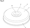
- FIG. 5 is a perspective view of the draining rubber 30 viewed from diagonally above.
- the draining rubber 30 has the disk-shaped base part 31 provided with a circular hole 30a into which the shaft 22 is inserted, the annular first protrusion 32 provided so as to protrude upward on the inner peripheral side of the base part 31, and a cylindrical portion 33 provided so as to extend downward on an outer peripheral side of the base part 31.
- FIG. 6 is a perspective view of the waterproof cap 40 viewed from diagonally above
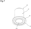
- FIG. 7 is a perspective view of the waterproof cap 40 viewed from diagonally below.
- the cylindrical portion 41 of the waterproof cap 40 has a hole 41a through which the shaft 22 penetrates.
- the flange part 42 is provided at a lower end of the cylindrical portion 41 so as to extend outward.
- the annular second protrusion 43 is provided so as to protrude downward on the lower surface and the outer peripheral side of the flange part 42.
- a taper 41b is formed so as to gradually decrease from an inner peripheral side to an outer peripheral side.
- the fan motor waterproof structure having the above configuration, by press-fitting the waterproof cap 40 (the tubular member) on the draining rubber 30 (the disk-shaped member) and on the outer periphery of the shaft 22, to cause the waterproof cap 40 to cover the boundary between the upper surface of the draining rubber 30 and the shaft 22, it is possible to prevent dust and water from accumulating at an interface between an exposed portion of the shaft 22 and the draining rubber 30.
- This can improve the waterproofness of the fan motor 20. Therefore, it is possible to prevent corrosion of the shaft 22 and entering of water into the motor body 21 along the shaft 22, and to prevent damage of the bearing and the like by the entering water.
- the space A formed between the draining rubber 30 and the waterproof cap 40 makes it possible to prevent radially inward infiltration, due to the capillary phenomenon, of the water having entered between the draining rubber 30 and the waterproof cap 40 from outside.
- flange part 42 at the lower end of the waterproof cap 40 enables the boundary between the upper surface of the draining rubber 30 and the shaft 22 to be reliably covered with the flange part 42, and the waterproofness is further improved.
- the taper 41b at the upper end of the cylindrical portion 41 of the waterproof cap 40 so as to gradually decrease from the inner peripheral side to the outer peripheral side, dust and water fall along the taper 41b and is less likely to accumulate on the upper end of the waterproof cap 40, which can reduce risk of water entering between the waterproof cap 40 and the shaft 22 from the upper end side of the waterproof cap 40.
- FIG. 8 is an enlarged cross-sectional view of a main part of a fan motor 20 of an outdoor unit using a fan motor waterproof structure of a second embodiment of the present disclosure.
- the outdoor unit using the fan motor waterproof structure of the second embodiment has the same configuration as the outdoor unit 1 of the first embodiment except for the fan motor waterproof structure, and FIGS. 1 to 3 are incorporated.
- a lower end face of an annular second protrusion 44 of a waterproof cap 40 is not in contact with an upper surface of a base part 31 of a draining rubber 30, and there is a gap between the annular second protrusion 44 of the waterproof cap 40 and the base part 31 of the draining rubber 30.
- the fan motor waterproof structure in the second embodiment is different from the fan motor waterproof structure in the first embodiment in that a space A formed between the draining rubber 30 and the waterproof cap 40 is connected to an open space on a radially outer side.
- the fan motor waterproof structure of the second embodiment has an effect similar to that of the fan motor waterproof structure of the first embodiment.
- the space A formed between the draining rubber 30 and the waterproof cap 40 is connected to the open space on the radially outer side, it is possible to cause water having been blocked from entering in the space A between the draining rubber 30 and the waterproof cap 40 to be discharged outside along with rotation of the shaft 22, and to prevent accumulation of water between the draining rubber 30 and the waterproof cap 40.
- the flange part 42 is provided at the lower end of the cylindrical portion 41 of the waterproof cap 40, which is the tubular member, so as to extend outward.
- the flange part may be omitted, and a thickness of the tubular member in the radial direction may be increased, for example, to cover a boundary between the upper surface of the disk-shaped member and the shaft.
- the labyrinth seal is formed by providing the annular first protrusion 32 on the draining rubber 30, which is the disk-shaped member, and the annular second protrusion 43 or 44 on the flange part 42 of the waterproof cap 40, which is the tubular member.
- the labyrinth seal by providing the annular first protrusion protruding upward on the upper surface of the disk-shaped member and at a position facing the outer periphery of the flange part of the tubular member, and providing the annular second protrusion so as to protrude downward on the lower surface and the inner peripheral side of the flange part of the tubular member.
- the labyrinth seal may be formed by providing two or more of at least one of the annular first protrusion of the disk-shaped member or the annular second protrusion of the tubular member at intervals in the radial direction.
- the labyrinth seal by the annular first protrusion of the disk-shaped member and the annular second protrusion of the tubular member may be omitted. In this case as well, it is possible to prevent dust and water from accumulating at the interface between the exposed portion of the shaft and the disk-shaped member.
- individual end faces of the draining rubber 30 (the disk-shaped member) and the waterproof cap 40 (the tubular member) facing each other with the space A interposed in between may have a plurality of faces having different heights, and at least one of the plurality of faces of the draining rubber 30 may be located above at least one of the plurality of faces of the waterproof cap 40. This forms a maze between the draining rubber 30 and the waterproof cap 40, which can effectively prevent entering of water between the draining rubber 30 and the waterproof cap 40.
- ethylene propylene diene rubber (EPDM) or the like is used as a material for the draining rubber 30, which is the disk-shaped member, and the waterproof cap 40, which is the tubular member.
- EPDM ethylene propylene diene rubber
- the material of the disk-shaped member and the tubular member is not limited to this, and a material having water repellency and weather resistance is preferable.
- the draining rubber 30, which is the disk-shaped member is fitted and positioned on the annular step part 22a provided on the shaft 22, but the disk-shaped member may be positioned using an E-ring fitted to the shaft.
Landscapes
- Engineering & Computer Science (AREA)
- Power Engineering (AREA)
- Mechanical Engineering (AREA)
- General Engineering & Computer Science (AREA)
- Motor Or Generator Frames (AREA)
- Connection Of Motors, Electrical Generators, Mechanical Devices, And The Like (AREA)
Claims (5)
- Structure étanche à l'eau de moteur de ventilateur comprenant :un moteur de ventilateur (20) agencé avec un arbre (22) saillant vers le haut depuis un corps de moteur (21), l'arbre (22) étant configuré pour être fixé à un ventilateur (10) ; etun élément en forme de disque (30) ajusté sur un extérieur d'une partie saillante de l'arbre (22) du moteur de ventilateur (20) sur le côté du corps de moteur (21) ;caractérisée en ce quela structure étanche à l'eau de moteur de ventilateur comprend en outre un élément tubulaire (40) ajusté par pression sur une périphérie extérieure de l'arbre (22), un espace (A) étant formé entre l'élément en forme de disque (30) et l'élément tubulaire (40) avec une face d'extrémité inférieure de l'élément tubulaire (40) étant en contact avec une surface supérieure de l'élément en forme de disque (30) ou n'étant pas en contact avec la surface supérieure de l'élément en forme de disque (30), l'élément tubulaire (40) recouvrant une limite entre une surface supérieure de l'élément en forme de disque (30) et l'arbre (22), dans laquelleà une extrémité inférieure de l'élément tubulaire (40), une partie de bridge (42) est prévue,il est prévu une première saillie annulaire (32) saillante vers le haut sur une surface supérieure et un côté périphérique intérieur de l'élément en forme de disque (30),il est prévu une seconde saillie annulaire (43, 44) saillante vers le bas sur une surface inférieure et un côté périphérique extérieur de la partie de bride (42) de l'élément tubulaire (40), etun joint en labyrinthe est formé par la première saillie annulaire (32) de l'élément en forme de disque (30) et la seconde saillie annulaire (43, 44) de l'élément tubulaire (40).
- Structure étanche à l'eau de moteur de ventilateur selon la revendication 1, dans laquelle
un espace (A) est formé entre l'élément en forme de disque (30) et l'élément tubulaire (40), et l'espace (A) est relié à un espace ouvert sur un côté radialement extérieur. - Structure étanche à l'eau de moteur de ventilateur comprenant :un moteur de ventilateur (20) agencé avec un arbre (22) saillant vers le haut depuis un corps de moteur (21), l'arbre (22) étant configuré pour être fixé à un ventilateur (10) ; etun élément en forme de disque (30) ajusté sur un extérieur d'une partie saillante de l'arbre (22) du moteur de ventilateur (20) sur le côté du corps de moteur (21) ;caractérisée en ce quela structure étanche à l'eau de moteur de ventilateur comprend en outre un élément tubulaire (40) ajusté par pression sur une périphérie extérieure de l'arbre (22), un espace (A) étant formé entre l'élément en forme de disque (30) et l'élément tubulaire (40) avec une face d'extrémité inférieure de l'élément tubulaire (40) étant en contact avec une surface supérieure de l'élément en forme de disque (30) ou n'étant pas en contact avec la surface supérieure de l'élément en forme de disque (30), l'élément tubulaire (40) recouvrant une limite entre une surface supérieure de l'élément en forme de disque (30) et l'arbre (22), dans laquelleun espace (A) est formé entre l'élément en forme de disque (30) et l'élément tubulaire (40), et l'espace (A) est relié à un espace ouvert sur un côté radialement extérieur etdes faces d'extrémité individuelles de l'élément en forme de disque (30) et de l'élément tubulaire (40) sont orientées l'une vers l'autre avec l'espace (A) interposé entre elles, et comportent une pluralité de faces présentant des hauteurs différentes, etau moins une face parmi la pluralité de faces de l'élément en forme de disque (30) est située au-dessus d'au moins une face parmi la pluralité de faces de l'élément tubulaire (40).
- Structure étanche à l'eau de moteur de ventilateur selon l'une quelconque des revendications 1 à 3, dans laquelle
à une extrémité inférieure de l'élément tubulaire (40), une partie de bridge (42) est prévue. - Structure étanche à l'eau de moteur de ventilateur selon l'une quelconque des revendications 1 à 4, dans laquelle
un cône (41b) est formé à une extrémité supérieure de l'élément tubulaire (40) pour décroître progressivement d'un côté périphérique intérieur vers un côté périphérique extérieur.
Applications Claiming Priority (2)
| Application Number | Priority Date | Filing Date | Title |
|---|---|---|---|
| JP2018230915A JP6848957B2 (ja) | 2018-12-10 | 2018-12-10 | ファンモータ防水構造 |
| PCT/JP2019/043608 WO2020121698A1 (fr) | 2018-12-10 | 2019-11-07 | Structure étanche à l'eau de moteur de ventilateur |
Publications (3)
| Publication Number | Publication Date |
|---|---|
| EP3876398A1 EP3876398A1 (fr) | 2021-09-08 |
| EP3876398A4 EP3876398A4 (fr) | 2021-12-29 |
| EP3876398B1 true EP3876398B1 (fr) | 2023-06-21 |
Family
ID=71076322
Family Applications (1)
| Application Number | Title | Priority Date | Filing Date |
|---|---|---|---|
| EP19896498.3A Active EP3876398B1 (fr) | 2018-12-10 | 2019-11-07 | Structure étanche à l'eau de moteur de ventilateur |
Country Status (6)
| Country | Link |
|---|---|
| US (1) | US11764634B2 (fr) |
| EP (1) | EP3876398B1 (fr) |
| JP (1) | JP6848957B2 (fr) |
| CN (1) | CN112840533B (fr) |
| ES (1) | ES2949567T3 (fr) |
| WO (1) | WO2020121698A1 (fr) |
Families Citing this family (1)
| Publication number | Priority date | Publication date | Assignee | Title |
|---|---|---|---|---|
| US20250233474A1 (en) * | 2022-04-14 | 2025-07-17 | Minebea Mitsumi Inc. | Motor |
Citations (1)
| Publication number | Priority date | Publication date | Assignee | Title |
|---|---|---|---|---|
| US20060181247A1 (en) * | 2005-02-16 | 2006-08-17 | Panasonic Ev Energy Co., Ltd. | Fan structure and battery pack using the same |
Family Cites Families (6)
| Publication number | Priority date | Publication date | Assignee | Title |
|---|---|---|---|---|
| JPS54180210U (fr) * | 1978-06-09 | 1979-12-20 | ||
| JPH038060Y2 (fr) | 1985-07-19 | 1991-02-27 | ||
| CN2229566Y (zh) * | 1995-04-13 | 1996-06-19 | 长春市北方变压器组件研究所 | 变压器风扇轴伸迷宫式密封防护装置 |
| JP6046466B2 (ja) * | 2012-11-26 | 2016-12-14 | 住友重機械工業株式会社 | モータの防水構造 |
| CN103742430B (zh) * | 2013-12-19 | 2015-05-27 | 浙江双双制冷设备有限公司 | 一种离心风机用电机组件 |
| JP6320555B2 (ja) | 2014-10-24 | 2018-05-09 | 三菱電機株式会社 | 電動機の固定子、電動機および空気調和機 |
-
2018
- 2018-12-10 JP JP2018230915A patent/JP6848957B2/ja active Active
-
2019
- 2019-11-07 EP EP19896498.3A patent/EP3876398B1/fr active Active
- 2019-11-07 WO PCT/JP2019/043608 patent/WO2020121698A1/fr not_active Ceased
- 2019-11-07 ES ES19896498T patent/ES2949567T3/es active Active
- 2019-11-07 US US17/311,919 patent/US11764634B2/en active Active
- 2019-11-07 CN CN201980067138.4A patent/CN112840533B/zh active Active
Patent Citations (1)
| Publication number | Priority date | Publication date | Assignee | Title |
|---|---|---|---|---|
| US20060181247A1 (en) * | 2005-02-16 | 2006-08-17 | Panasonic Ev Energy Co., Ltd. | Fan structure and battery pack using the same |
Also Published As
| Publication number | Publication date |
|---|---|
| JP6848957B2 (ja) | 2021-03-24 |
| EP3876398A4 (fr) | 2021-12-29 |
| US11764634B2 (en) | 2023-09-19 |
| US20220029499A1 (en) | 2022-01-27 |
| ES2949567T3 (es) | 2023-09-29 |
| WO2020121698A1 (fr) | 2020-06-18 |
| JP2020096406A (ja) | 2020-06-18 |
| CN112840533A (zh) | 2021-05-25 |
| CN112840533B (zh) | 2024-06-18 |
| EP3876398A1 (fr) | 2021-09-08 |
Similar Documents
| Publication | Publication Date | Title |
|---|---|---|
| US8678785B2 (en) | Ventilation fan | |
| US9033680B2 (en) | Electric fan | |
| JP7031290B2 (ja) | 送風機 | |
| US20230220881A1 (en) | Bearing device with integrated electrical insulation, in particular for an electric motor or machine | |
| JP6354309B2 (ja) | ブロワ装置 | |
| JP2016008579A (ja) | 軸流送風機 | |
| JPWO2012096247A1 (ja) | 電動ファン | |
| EP3876398B1 (fr) | Structure étanche à l'eau de moteur de ventilateur | |
| US20210234426A1 (en) | Bearing cap and electric motor utilizing the same | |
| US6595692B2 (en) | Rotation sensor-equipped bearing | |
| EP1412641B1 (fr) | Unite de ventilation | |
| JP2008278690A (ja) | 電動モータ | |
| US2743385A (en) | Vertical dynamoelectric machine | |
| KR102041050B1 (ko) | 일체형 로터를 갖는 팬 모터 | |
| JP2015142437A (ja) | 電動機 | |
| US11025123B2 (en) | Motor and fan motor | |
| US20220320982A1 (en) | Motor and electrical product | |
| JP2009024649A (ja) | 防滴構造を備えた遠心ファン | |
| JP3795991B2 (ja) | ファン駆動用モータの防水構造 | |
| WO2024252803A1 (fr) | Machine électrique tournante | |
| US5846051A (en) | Sealing device for dust- and liquid-aspirating machines | |
| CN211314649U (zh) | 离心风扇和送风装置 | |
| JP7243292B2 (ja) | モータ | |
| WO2017222055A1 (fr) | Dispositif de soufflage | |
| CN205622383U (zh) | 马达及风扇 |
Legal Events
| Date | Code | Title | Description |
|---|---|---|---|
| STAA | Information on the status of an ep patent application or granted ep patent |
Free format text: STATUS: THE INTERNATIONAL PUBLICATION HAS BEEN MADE |
|
| PUAI | Public reference made under article 153(3) epc to a published international application that has entered the european phase |
Free format text: ORIGINAL CODE: 0009012 |
|
| STAA | Information on the status of an ep patent application or granted ep patent |
Free format text: STATUS: REQUEST FOR EXAMINATION WAS MADE |
|
| 17P | Request for examination filed |
Effective date: 20210531 |
|
| AK | Designated contracting states |
Kind code of ref document: A1 Designated state(s): AL AT BE BG CH CY CZ DE DK EE ES FI FR GB GR HR HU IE IS IT LI LT LU LV MC MK MT NL NO PL PT RO RS SE SI SK SM TR |
|
| A4 | Supplementary search report drawn up and despatched |
Effective date: 20211126 |
|
| RIC1 | Information provided on ipc code assigned before grant |
Ipc: F04D 29/64 20060101ALI20211122BHEP Ipc: F04D 29/10 20060101ALI20211122BHEP Ipc: H02K 7/14 20060101ALI20211122BHEP Ipc: H02K 5/10 20060101AFI20211122BHEP |
|
| DAV | Request for validation of the european patent (deleted) | ||
| DAX | Request for extension of the european patent (deleted) | ||
| STAA | Information on the status of an ep patent application or granted ep patent |
Free format text: STATUS: EXAMINATION IS IN PROGRESS |
|
| 17Q | First examination report despatched |
Effective date: 20220811 |
|
| RAP3 | Party data changed (applicant data changed or rights of an application transferred) |
Owner name: DAIKIN INDUSTRIES, LTD. |
|
| GRAP | Despatch of communication of intention to grant a patent |
Free format text: ORIGINAL CODE: EPIDOSNIGR1 |
|
| STAA | Information on the status of an ep patent application or granted ep patent |
Free format text: STATUS: GRANT OF PATENT IS INTENDED |
|
| INTG | Intention to grant announced |
Effective date: 20230223 |
|
| GRAS | Grant fee paid |
Free format text: ORIGINAL CODE: EPIDOSNIGR3 |
|
| GRAA | (expected) grant |
Free format text: ORIGINAL CODE: 0009210 |
|
| STAA | Information on the status of an ep patent application or granted ep patent |
Free format text: STATUS: THE PATENT HAS BEEN GRANTED |
|
| AK | Designated contracting states |
Kind code of ref document: B1 Designated state(s): AL AT BE BG CH CY CZ DE DK EE ES FI FR GB GR HR HU IE IS IT LI LT LU LV MC MK MT NL NO PL PT RO RS SE SI SK SM TR |
|
| REG | Reference to a national code |
Ref country code: CH Ref legal event code: EP |
|
| P01 | Opt-out of the competence of the unified patent court (upc) registered |
Effective date: 20230525 |
|
| REG | Reference to a national code |
Ref country code: DE Ref legal event code: R096 Ref document number: 602019031513 Country of ref document: DE |
|
| REG | Reference to a national code |
Ref country code: AT Ref legal event code: REF Ref document number: 1581621 Country of ref document: AT Kind code of ref document: T Effective date: 20230715 |
|
| REG | Reference to a national code |
Ref country code: IE Ref legal event code: FG4D |
|
| REG | Reference to a national code |
Ref country code: ES Ref legal event code: FG2A Ref document number: 2949567 Country of ref document: ES Kind code of ref document: T3 Effective date: 20230929 |
|
| REG | Reference to a national code |
Ref country code: LT Ref legal event code: MG9D |
|
| REG | Reference to a national code |
Ref country code: NL Ref legal event code: MP Effective date: 20230621 |
|
| PG25 | Lapsed in a contracting state [announced via postgrant information from national office to epo] |
Ref country code: SE Free format text: LAPSE BECAUSE OF FAILURE TO SUBMIT A TRANSLATION OF THE DESCRIPTION OR TO PAY THE FEE WITHIN THE PRESCRIBED TIME-LIMIT Effective date: 20230621 Ref country code: NO Free format text: LAPSE BECAUSE OF FAILURE TO SUBMIT A TRANSLATION OF THE DESCRIPTION OR TO PAY THE FEE WITHIN THE PRESCRIBED TIME-LIMIT Effective date: 20230921 |
|
| REG | Reference to a national code |
Ref country code: AT Ref legal event code: MK05 Ref document number: 1581621 Country of ref document: AT Kind code of ref document: T Effective date: 20230621 |
|
| PG25 | Lapsed in a contracting state [announced via postgrant information from national office to epo] |
Ref country code: RS Free format text: LAPSE BECAUSE OF FAILURE TO SUBMIT A TRANSLATION OF THE DESCRIPTION OR TO PAY THE FEE WITHIN THE PRESCRIBED TIME-LIMIT Effective date: 20230621 Ref country code: NL Free format text: LAPSE BECAUSE OF FAILURE TO SUBMIT A TRANSLATION OF THE DESCRIPTION OR TO PAY THE FEE WITHIN THE PRESCRIBED TIME-LIMIT Effective date: 20230621 Ref country code: LV Free format text: LAPSE BECAUSE OF FAILURE TO SUBMIT A TRANSLATION OF THE DESCRIPTION OR TO PAY THE FEE WITHIN THE PRESCRIBED TIME-LIMIT Effective date: 20230621 Ref country code: LT Free format text: LAPSE BECAUSE OF FAILURE TO SUBMIT A TRANSLATION OF THE DESCRIPTION OR TO PAY THE FEE WITHIN THE PRESCRIBED TIME-LIMIT Effective date: 20230621 Ref country code: HR Free format text: LAPSE BECAUSE OF FAILURE TO SUBMIT A TRANSLATION OF THE DESCRIPTION OR TO PAY THE FEE WITHIN THE PRESCRIBED TIME-LIMIT Effective date: 20230621 Ref country code: GR Free format text: LAPSE BECAUSE OF FAILURE TO SUBMIT A TRANSLATION OF THE DESCRIPTION OR TO PAY THE FEE WITHIN THE PRESCRIBED TIME-LIMIT Effective date: 20230922 |
|
| PG25 | Lapsed in a contracting state [announced via postgrant information from national office to epo] |
Ref country code: FI Free format text: LAPSE BECAUSE OF FAILURE TO SUBMIT A TRANSLATION OF THE DESCRIPTION OR TO PAY THE FEE WITHIN THE PRESCRIBED TIME-LIMIT Effective date: 20230621 |
|
| PG25 | Lapsed in a contracting state [announced via postgrant information from national office to epo] |
Ref country code: SK Free format text: LAPSE BECAUSE OF FAILURE TO SUBMIT A TRANSLATION OF THE DESCRIPTION OR TO PAY THE FEE WITHIN THE PRESCRIBED TIME-LIMIT Effective date: 20230621 |
|
| PG25 | Lapsed in a contracting state [announced via postgrant information from national office to epo] |
Ref country code: IS Free format text: LAPSE BECAUSE OF FAILURE TO SUBMIT A TRANSLATION OF THE DESCRIPTION OR TO PAY THE FEE WITHIN THE PRESCRIBED TIME-LIMIT Effective date: 20231021 |
|
| PG25 | Lapsed in a contracting state [announced via postgrant information from national office to epo] |
Ref country code: SM Free format text: LAPSE BECAUSE OF FAILURE TO SUBMIT A TRANSLATION OF THE DESCRIPTION OR TO PAY THE FEE WITHIN THE PRESCRIBED TIME-LIMIT Effective date: 20230621 Ref country code: SK Free format text: LAPSE BECAUSE OF FAILURE TO SUBMIT A TRANSLATION OF THE DESCRIPTION OR TO PAY THE FEE WITHIN THE PRESCRIBED TIME-LIMIT Effective date: 20230621 Ref country code: RO Free format text: LAPSE BECAUSE OF FAILURE TO SUBMIT A TRANSLATION OF THE DESCRIPTION OR TO PAY THE FEE WITHIN THE PRESCRIBED TIME-LIMIT Effective date: 20230621 Ref country code: PT Free format text: LAPSE BECAUSE OF FAILURE TO SUBMIT A TRANSLATION OF THE DESCRIPTION OR TO PAY THE FEE WITHIN THE PRESCRIBED TIME-LIMIT Effective date: 20231023 Ref country code: IS Free format text: LAPSE BECAUSE OF FAILURE TO SUBMIT A TRANSLATION OF THE DESCRIPTION OR TO PAY THE FEE WITHIN THE PRESCRIBED TIME-LIMIT Effective date: 20231021 Ref country code: EE Free format text: LAPSE BECAUSE OF FAILURE TO SUBMIT A TRANSLATION OF THE DESCRIPTION OR TO PAY THE FEE WITHIN THE PRESCRIBED TIME-LIMIT Effective date: 20230621 Ref country code: CZ Free format text: LAPSE BECAUSE OF FAILURE TO SUBMIT A TRANSLATION OF THE DESCRIPTION OR TO PAY THE FEE WITHIN THE PRESCRIBED TIME-LIMIT Effective date: 20230621 Ref country code: AT Free format text: LAPSE BECAUSE OF FAILURE TO SUBMIT A TRANSLATION OF THE DESCRIPTION OR TO PAY THE FEE WITHIN THE PRESCRIBED TIME-LIMIT Effective date: 20230621 |
|
| PG25 | Lapsed in a contracting state [announced via postgrant information from national office to epo] |
Ref country code: PL Free format text: LAPSE BECAUSE OF FAILURE TO SUBMIT A TRANSLATION OF THE DESCRIPTION OR TO PAY THE FEE WITHIN THE PRESCRIBED TIME-LIMIT Effective date: 20230621 |
|
| REG | Reference to a national code |
Ref country code: DE Ref legal event code: R097 Ref document number: 602019031513 Country of ref document: DE |
|
| PLBE | No opposition filed within time limit |
Free format text: ORIGINAL CODE: 0009261 |
|
| STAA | Information on the status of an ep patent application or granted ep patent |
Free format text: STATUS: NO OPPOSITION FILED WITHIN TIME LIMIT |
|
| PG25 | Lapsed in a contracting state [announced via postgrant information from national office to epo] |
Ref country code: DK Free format text: LAPSE BECAUSE OF FAILURE TO SUBMIT A TRANSLATION OF THE DESCRIPTION OR TO PAY THE FEE WITHIN THE PRESCRIBED TIME-LIMIT Effective date: 20230621 |
|
| PG25 | Lapsed in a contracting state [announced via postgrant information from national office to epo] |
Ref country code: SI Free format text: LAPSE BECAUSE OF FAILURE TO SUBMIT A TRANSLATION OF THE DESCRIPTION OR TO PAY THE FEE WITHIN THE PRESCRIBED TIME-LIMIT Effective date: 20230621 |
|
| 26N | No opposition filed |
Effective date: 20240322 |
|
| PG25 | Lapsed in a contracting state [announced via postgrant information from national office to epo] |
Ref country code: SI Free format text: LAPSE BECAUSE OF FAILURE TO SUBMIT A TRANSLATION OF THE DESCRIPTION OR TO PAY THE FEE WITHIN THE PRESCRIBED TIME-LIMIT Effective date: 20230621 |
|
| REG | Reference to a national code |
Ref country code: CH Ref legal event code: PL |
|
| PG25 | Lapsed in a contracting state [announced via postgrant information from national office to epo] |
Ref country code: MC Free format text: LAPSE BECAUSE OF FAILURE TO SUBMIT A TRANSLATION OF THE DESCRIPTION OR TO PAY THE FEE WITHIN THE PRESCRIBED TIME-LIMIT Effective date: 20230621 |
|
| PG25 | Lapsed in a contracting state [announced via postgrant information from national office to epo] |
Ref country code: LU Free format text: LAPSE BECAUSE OF NON-PAYMENT OF DUE FEES Effective date: 20231107 |
|
| PG25 | Lapsed in a contracting state [announced via postgrant information from national office to epo] |
Ref country code: CH Free format text: LAPSE BECAUSE OF NON-PAYMENT OF DUE FEES Effective date: 20231130 |
|
| PG25 | Lapsed in a contracting state [announced via postgrant information from national office to epo] |
Ref country code: MC Free format text: LAPSE BECAUSE OF FAILURE TO SUBMIT A TRANSLATION OF THE DESCRIPTION OR TO PAY THE FEE WITHIN THE PRESCRIBED TIME-LIMIT Effective date: 20230621 Ref country code: LU Free format text: LAPSE BECAUSE OF NON-PAYMENT OF DUE FEES Effective date: 20231107 Ref country code: CH Free format text: LAPSE BECAUSE OF NON-PAYMENT OF DUE FEES Effective date: 20231130 |
|
| REG | Reference to a national code |
Ref country code: BE Ref legal event code: MM Effective date: 20231130 |
|
| REG | Reference to a national code |
Ref country code: IE Ref legal event code: MM4A |
|
| PG25 | Lapsed in a contracting state [announced via postgrant information from national office to epo] |
Ref country code: IE Free format text: LAPSE BECAUSE OF NON-PAYMENT OF DUE FEES Effective date: 20231107 |
|
| PG25 | Lapsed in a contracting state [announced via postgrant information from national office to epo] |
Ref country code: BE Free format text: LAPSE BECAUSE OF NON-PAYMENT OF DUE FEES Effective date: 20231130 |
|
| PG25 | Lapsed in a contracting state [announced via postgrant information from national office to epo] |
Ref country code: IE Free format text: LAPSE BECAUSE OF NON-PAYMENT OF DUE FEES Effective date: 20231107 Ref country code: BE Free format text: LAPSE BECAUSE OF NON-PAYMENT OF DUE FEES Effective date: 20231130 |
|
| PG25 | Lapsed in a contracting state [announced via postgrant information from national office to epo] |
Ref country code: BG Free format text: LAPSE BECAUSE OF FAILURE TO SUBMIT A TRANSLATION OF THE DESCRIPTION OR TO PAY THE FEE WITHIN THE PRESCRIBED TIME-LIMIT Effective date: 20230621 |
|
| PG25 | Lapsed in a contracting state [announced via postgrant information from national office to epo] |
Ref country code: BG Free format text: LAPSE BECAUSE OF FAILURE TO SUBMIT A TRANSLATION OF THE DESCRIPTION OR TO PAY THE FEE WITHIN THE PRESCRIBED TIME-LIMIT Effective date: 20230621 |
|
| PG25 | Lapsed in a contracting state [announced via postgrant information from national office to epo] |
Ref country code: CY Free format text: LAPSE BECAUSE OF FAILURE TO SUBMIT A TRANSLATION OF THE DESCRIPTION OR TO PAY THE FEE WITHIN THE PRESCRIBED TIME-LIMIT; INVALID AB INITIO Effective date: 20191107 |
|
| PG25 | Lapsed in a contracting state [announced via postgrant information from national office to epo] |
Ref country code: HU Free format text: LAPSE BECAUSE OF FAILURE TO SUBMIT A TRANSLATION OF THE DESCRIPTION OR TO PAY THE FEE WITHIN THE PRESCRIBED TIME-LIMIT; INVALID AB INITIO Effective date: 20191107 |
|
| PG25 | Lapsed in a contracting state [announced via postgrant information from national office to epo] |
Ref country code: TR Free format text: LAPSE BECAUSE OF FAILURE TO SUBMIT A TRANSLATION OF THE DESCRIPTION OR TO PAY THE FEE WITHIN THE PRESCRIBED TIME-LIMIT Effective date: 20230621 |
|
| PGFP | Annual fee paid to national office [announced via postgrant information from national office to epo] |
Ref country code: DE Payment date: 20251119 Year of fee payment: 7 |
|
| PGFP | Annual fee paid to national office [announced via postgrant information from national office to epo] |
Ref country code: GB Payment date: 20251121 Year of fee payment: 7 |
|
| PGFP | Annual fee paid to national office [announced via postgrant information from national office to epo] |
Ref country code: IT Payment date: 20251125 Year of fee payment: 7 |
|
| PGFP | Annual fee paid to national office [announced via postgrant information from national office to epo] |
Ref country code: FR Payment date: 20251126 Year of fee payment: 7 |
|
| PGFP | Annual fee paid to national office [announced via postgrant information from national office to epo] |
Ref country code: ES Payment date: 20251229 Year of fee payment: 7 |