EP3876420A1 - Transmission de fréquence radio - Google Patents
Transmission de fréquence radio Download PDFInfo
- Publication number
- EP3876420A1 EP3876420A1 EP20160345.3A EP20160345A EP3876420A1 EP 3876420 A1 EP3876420 A1 EP 3876420A1 EP 20160345 A EP20160345 A EP 20160345A EP 3876420 A1 EP3876420 A1 EP 3876420A1
- Authority
- EP
- European Patent Office
- Prior art keywords
- outphasing
- path
- envelope
- phase control
- substantially constant
- Prior art date
- Legal status (The legal status is an assumption and is not a legal conclusion. Google has not performed a legal analysis and makes no representation as to the accuracy of the status listed.)
- Granted
Links
Images


Classifications
-
- H—ELECTRICITY
- H04—ELECTRIC COMMUNICATION TECHNIQUE
- H04L—TRANSMISSION OF DIGITAL INFORMATION, e.g. TELEGRAPHIC COMMUNICATION
- H04L27/00—Modulated-carrier systems
- H04L27/32—Carrier systems characterised by combinations of two or more of the types covered by groups H04L27/02, H04L27/10, H04L27/18 or H04L27/26
- H04L27/34—Amplitude- and phase-modulated carrier systems, e.g. quadrature-amplitude modulated carrier systems
- H04L27/345—Modifications of the signal space to allow the transmission of additional information
- H04L27/3461—Modifications of the signal space to allow the transmission of additional information in order to transmit a subchannel
- H04L27/3483—Modifications of the signal space to allow the transmission of additional information in order to transmit a subchannel using a modulation of the constellation points
-
- H—ELECTRICITY
- H03—ELECTRONIC CIRCUITRY
- H03F—AMPLIFIERS
- H03F3/00—Amplifiers with only discharge tubes or only semiconductor devices as amplifying elements
- H03F3/189—High-frequency amplifiers, e.g. radio frequency amplifiers
- H03F3/19—High-frequency amplifiers, e.g. radio frequency amplifiers with semiconductor devices only
-
- H—ELECTRICITY
- H03—ELECTRONIC CIRCUITRY
- H03F—AMPLIFIERS
- H03F1/00—Details of amplifiers with only discharge tubes, only semiconductor devices or only unspecified devices as amplifying elements
- H03F1/26—Modifications of amplifiers to reduce influence of noise generated by amplifying elements
-
- H—ELECTRICITY
- H03—ELECTRONIC CIRCUITRY
- H03F—AMPLIFIERS
- H03F1/00—Details of amplifiers with only discharge tubes, only semiconductor devices or only unspecified devices as amplifying elements
- H03F1/02—Modifications of amplifiers to raise the efficiency, e.g. gliding Class A stages, use of an auxiliary oscillation
- H03F1/0205—Modifications of amplifiers to raise the efficiency, e.g. gliding Class A stages, use of an auxiliary oscillation in transistor amplifiers
- H03F1/0294—Modifications of amplifiers to raise the efficiency, e.g. gliding Class A stages, use of an auxiliary oscillation in transistor amplifiers using vector summing of two or more constant amplitude phase-modulated signals
-
- H—ELECTRICITY
- H03—ELECTRONIC CIRCUITRY
- H03F—AMPLIFIERS
- H03F3/00—Amplifiers with only discharge tubes or only semiconductor devices as amplifying elements
- H03F3/20—Power amplifiers, e.g. Class B amplifiers, Class C amplifiers
- H03F3/21—Power amplifiers, e.g. Class B amplifiers, Class C amplifiers with semiconductor devices only
- H03F3/211—Power amplifiers, e.g. Class B amplifiers, Class C amplifiers with semiconductor devices only using a combination of several amplifiers
-
- H—ELECTRICITY
- H03—ELECTRONIC CIRCUITRY
- H03F—AMPLIFIERS
- H03F3/00—Amplifiers with only discharge tubes or only semiconductor devices as amplifying elements
- H03F3/20—Power amplifiers, e.g. Class B amplifiers, Class C amplifiers
- H03F3/21—Power amplifiers, e.g. Class B amplifiers, Class C amplifiers with semiconductor devices only
- H03F3/217—Class D power amplifiers; Switching amplifiers
- H03F3/2176—Class E amplifiers
-
- H—ELECTRICITY
- H03—ELECTRONIC CIRCUITRY
- H03F—AMPLIFIERS
- H03F3/00—Amplifiers with only discharge tubes or only semiconductor devices as amplifying elements
- H03F3/20—Power amplifiers, e.g. Class B amplifiers, Class C amplifiers
- H03F3/24—Power amplifiers, e.g. Class B amplifiers, Class C amplifiers of transmitter output stages
- H03F3/245—Power amplifiers, e.g. Class B amplifiers, Class C amplifiers of transmitter output stages with semiconductor devices only
-
- H—ELECTRICITY
- H04—ELECTRIC COMMUNICATION TECHNIQUE
- H04B—TRANSMISSION
- H04B1/00—Details of transmission systems, not covered by a single one of groups H04B3/00 - H04B13/00; Details of transmission systems not characterised by the medium used for transmission
- H04B1/02—Transmitters
- H04B1/04—Circuits
-
- H—ELECTRICITY
- H03—ELECTRONIC CIRCUITRY
- H03F—AMPLIFIERS
- H03F2200/00—Indexing scheme relating to amplifiers
- H03F2200/451—Indexing scheme relating to amplifiers the amplifier being a radio frequency amplifier
-
- H—ELECTRICITY
- H04—ELECTRIC COMMUNICATION TECHNIQUE
- H04B—TRANSMISSION
- H04B1/00—Details of transmission systems, not covered by a single one of groups H04B3/00 - H04B13/00; Details of transmission systems not characterised by the medium used for transmission
- H04B1/02—Transmitters
- H04B1/04—Circuits
- H04B2001/0408—Circuits with power amplifiers
Definitions
- Embodiments of the present disclosure relate to radio frequency transmission.
- linear amplifiers are inefficient and can be expensive.
- an apparatus comprising:
- the means for discrete phase control in each outphasing path is configured to define, for the outphasing path, a constellation point in a constant envelope constellation diagram.
- the apparatus comprises means for providing discrete phase control in each outphasing path to define, for each outphasing path, a constellation point in the constant envelope constellation diagram and thereby define a target constellation point in the non-constant-envelope constellation diagram for the output signal.
- each outphasing path comprises a phase controller that enables discrete phase control in the outphasing path, wherein the phase controller is configured to phase modulate a carrier wave.
- the amplifier in each outphasing path is a non-linear amplifier configured for amplification of the substantially constant-envelope component received by the outphasing path.
- the apparatus comprises means for providing the combined output signals of the outphasing paths to an antenna for transmission.
- a system comprises for each one of a plurality of antennas, the apparatus.
- the system comprises means for controlling, for each antenna, discrete phase control in each outphasing path to define, for each outphasing path, a constellation point in a constant envelope constellation diagram and thereby define a target constellation point in a non-constant-envelope constellation diagram for each of the combined output signals provided to each of the antennas.
- the means for decomposing an input signal to multiple substantially constant-envelope components is configured to decompose the input signal to multiple substantially constant-envelope components for all antennas.
- the system comprises means for optimizing a cost function, across the plurality of antennas, to determine discrete phase control used for each outphasing path.
- the cost function is dependent upon total transmission power of the plurality of antennas and a measure of a difference between information intended to be received and information estimated to be received, as a consequence of providing the respective combined output signals of the outphasing paths to a respective antenna for transmission.
- the cost function is dependent upon efficiency, for example, power efficiency of the transmitter such as power added efficiency of the amplifier used.
- the cost function is additionally dependent upon interference, for example out of band transmission.
- a base station comprises the system.
- an apparatus comprising:
- the decomposing means for decomposing is configured to provide for joint spatial precoding and outphasing decomposition.
- each antenna input signal for a respective antenna defines a constellation point.
- the means for providing discrete phase control in each outphasing path is configured to define, for each outphasing path associated with an antenna, a constellation point in a constant envelope constellation diagram and thereby define a target constellation point in a non-constant-envelope constellation diagram for the input signal for the antenna.
- the transmitted signals from each antenna are combined over the air to generate a symbol of the input signal at a receiver.
- 'decompose' (and similar terms such as, for example, 'decomposition', 'decomposing' etc) is used in its normal mathematical sense to mean separation into component parts. It is not intended to have or connote an implied specific technical meaning, or be limited to application in a specific field or domain such as digital/analogue or linear/non-linear.
- non-linear precoding provides for joint (spatial) precoding and outphasing decomposition.
- the joint (spatial) precoding allows use of discrete phase control (instead of continuous phase control) to control each transmit antenna to transmit a constellation point (rather than a symbol). The signals from each antenna are then combined over the air to generate the symbol at the receiver.
- decomposition is achieved by joint (spatial) precoding and outphasing-decomposition.
- FIG 1 illustrates an example of an apparatus 100 comprising:
- the apparatus 100 comprises:
- the decomposing means 110 decomposes an input signal 101 to two substantially constant-envelope components S1, S2 per transmit antenna. There are two outphasing paths 120 1 , 120 2 per transmit antenna, the outputs of which are combined by the combining means 116.
- the decomposing means 110 decomposes an input signal 101 to M (M ⁇ 2) substantially constant-envelope components S1, S2...SM per transmit antenna and there are M outphasing paths 120 1 , 120 2 ...120 M per transmit antenna the outputs of which are combined by the combining means 116 for transmission by a transmit antenna.
- Circuitry 102 is outphasing transmit chain circuitry.
- the outphasing transmit chain circuitry 102 comprises one outphasing branch per transmit antenna.
- the outphasing branch comprises multiple (two in this example) outphasing paths 120 n and combining means 116.
- Each outphasing path 120 n provides for discrete phase control (discrete phase control means 112 n ) and for magnitude control (amplifier 114 n ).
- the discrete phase control means 112 n and amplifier 114 n are illustrated as series connected in a particular order. This order can, however, be reversed.
- Each outphasing path 120 n provides linear amplification, even when the amplifiers 114 n in the outphasing paths 120 n are non-linear.
- the apparatus 100 can therefore achieve linear amplification using cheaper and more energy efficient non-linear amplifiers rather than using linear amplifiers.
- the amplifier 114 n in each outphasing path 120 n is configured for linear amplification of the substantially constant-envelope component Sn received by the outphasing path 120 n .
- the amplifiers 114 n are non-linear power amplifiers.
- the same non-linear amplifier 114 n is used in each outphasing path 120 n .
- the non-linear amplifiers 114 n are class E or class F.
- the apparatus can be any suitable transmitter or transceiver. It can, for example, be a network node such as a base station, for example a cellular base station e.g. node-B in 3GPP, or can be a terminal, for example a cellular terminal e.g. mobile equipment (ME) or user equipment (UE) in 3GPP.
- a network node such as a base station, for example a cellular base station e.g. node-B in 3GPP
- a terminal for example a cellular terminal e.g. mobile equipment (ME) or user equipment (UE) in 3GPP.
- ME mobile equipment
- UE user equipment
- the decomposed signals S1, S2 are substantially constant envelope they can be amplified at the substantially constant envelope value in a linear fashion by the amplifier 114 n even if the amplifier 114 n has non-linear characteristics over a larger range of magnitudes. Therefore, each amplifier 114 n can operate in an efficient, non-linear mode.
- the sum of the multiple substantially constant-envelope components S1, S2 when transmitted enables substantial reproduction of the input signal 101 at a receiver.
- the multiple amplifiers 114 n are constant-envelope and therefore consume a fixed amount of power.
- Magnitude variation in the signal S overtime can be accommodated by varying, over time, the phase (angle) between S and S1 and between S and S2 without needing to vary the magnitude of S1 or the magnitude of S2.
- S1 and S2 are constant envelope.
- a substantially constant-envelope component Sn can fluctuate only within a narrow efficiency range of operation of the amplifier 114 n of the outphasing path 120 n that receives the constant-envelope component Sn.
- the signal S(t) can be decomposed from a sequence of inputs ⁇ S(t n ) ⁇ to a sequence of multiple components, each sequence of components ⁇ S1(t n ) ⁇ , ⁇ S2(t n ) ⁇ has a constant magnitude, over time, but has a phase that can be varied discretely over the sequence.
- the substantially constant-envelope components S1, S2 can be provided as substantially constant-envelope phasor components (digital domain) or substantially constant-envelope analogue signal components (analogue domain).
- Each outphasing path 120 n comprises means for:
- the discrete phase control means 112 n for discrete phase control in each outphasing path 120 n is configured to define, for the outphasing path 120 n , a constellation point 132 in a constant-envelope constellation diagram 130.
- An example of a suitable constant-envelope constellation diagram 130 is illustrated in FIG 3 .
- Each outphasing path 120 n has an associated (constant magnitude) constellation diagram 130. In some but not necessarily all examples, each outphasing path 120 n has the same associated (constant magnitude) constellation diagram 130.
- the combining means 116 for combining output signals from the outphasing paths 120 n , is configured to provide, as output 111, a signal associated with a constellation point 142 in a non-constant-envelope constellation diagram 140.
- the combining means 116 can, for example, add the output signals from the outphasing paths 120 n ,.
- An example of a non-constant-envelope constellation diagram 140 is illustrated in FIG 4 .
- the non-constant-envelope constellation diagram 140 is the constellation diagram formed by combining two signals that have the same associated constant magnitude constellation diagram 130 illustrated in FIG 3 .
- the constant-envelope constellation diagram 130 is characterized by quantized phases and a fixed magnitude.
- the constellation points lie on a circle, centered at the origin. In this example the constellation points are evenly distributed on the circumference of that circle.
- the discrete phase control means 112 n is configured to add a quantum of phase 2 ⁇ .m/N where 0 ⁇ m ⁇ N and N is the number of constant magnitude constellation points 132, for example, N can in some example equal 2 n where n is a natural number. In some examples, n is greater than or equal to 5. Adjacent constellation points 132 in the constant-envelope constellation diagram 130 are separated by a low resolution or quantized phase of 2 ⁇ /N.
- the non-constant-envelope constellation diagram 140 is characterized by quantized phases and quantized magnitudes.
- the constellation points lie on the origin or circles of different magnitude radius, centered at the origin.
- the constellation points 142 that are distributed on the circumferences of the circles are evenly distributed on the circumferences of the circles.
- the constellation points 142 for the combined signal are exp(2 ⁇ .m1/N) + exp(2 ⁇ .m2/N).
- the non-constant-envelope constellation diagram 140 has more constellation points 142 and a denser distribution of constellation points 142 than the constant-envelope constellation diagram 130.
- the discrete phase control means 112 n defines, for its outphasing path 120 n , a constellation point 132 in the constant-envelope constellation diagram 130. In combination, they define a target constellation point 142 in the non-constant-envelope constellation diagram 140 for the output signal 111.
- each outphasing path 120 n comprises a phase controller 112 n , controlled by the decomposed signals S1, S2, that enables discrete phase control in the outphasing path 120 n .
- the decomposition means 110 is configured to control the discrete phase control in each phase controller 112 n .
- phase controller 112 n is configured to phase modulate a carrier wave.
- the carrier wave is provided by a local oscillator (LO) 122 to each of the multiple phase controllers 112 n .
- the phase of the carrier wave is controlled by the phase controller 112 n , via the decomposed signal Sn, to have a constellation point 132 in a constant envelope constellation diagram.
- Each phase controller 112 n therefore provides discrete (e.g. quantized) phase control for its outphasing path 120 n .
- the signal, after discrete phase control is amplified by the respective amplifier 114 n of the outphasing path 120 n .
- the combining means 116 combines the amplified output signals from the outphasing paths 120 n to produce, as output, an amplified version of the carrier wave that has a target constellation point 142 in a non-constant envelope constellation diagram 140.
- the combined output signal 111 of the outphasing paths 120 n is provided to an antenna 150 for transmission.
- Circuitry 102 is outphasing transmit chain circuitry.
- the outphasing transmit chain circuitry 102 comprises one outphasing branch per transmit antenna.
- each outphasing branch comprises multiple (two in this example) outphasing paths 120 n and comprises combining means 116.
- the signal 101 is provided via an Evolved Common Public Radio Interface (eCPRI).
- eCPRI Evolved Common Public Radio Interface
- REC Radio Equipment Control
- RE Radio Equipment
- the interface can transport baseband I/Q signals to the radio equipment.
- Other interfaces can be used.
- the combining means 116 is an isolating combiner. Other combiners can be used.
- the decomposition means 110 comprises circuitry for precoding.
- the circuitry decomposes the input signal 101 to multiple substantially constant-envelope components Sn for multiple respective outphasing paths 120 n .
- the circuitry for precoding can provide additional phase control. For example, controlling the signals provided to the outphasing paths 120 n so that when the signals from the outphasing paths 120 n are combined by combining means 116, for all outphasing paths of all antennas, a target symbol, for example an OFDM symbol, is obtained.
- a target symbol for example an OFDM symbol
- An OFDM symbol cannot be generated at each antenna 150 when only low-resolution phase shifters 112 n are used. Instead, the signals from each antenna 150 are combined 'over the air' to generate the OFDM symbol at the UE.
- the (over-the-air) sum of all outphasing branches (not only the ones that are combined in a single Tx path) re-creates the wanted signal, input signal 101, in a pre-determined spatial direction (i.e., beam).
- This multi-antenna/over-the-air combining enables the use of efficient/quantized outphasing paths and branches.
- Outphasing transmit chain circuitry 102 provides, per transmit antenna 150, one outphasing branch which comprises multiple (two in this example) outphasing paths 120 n and combining means 116.
- outphasing branches each consisting of a plurality of outphasing paths 120 n , a nonlinear power amplifier per outphasing path, and a single combiner.
- the output of each outphasing branch is a constellation point 142 from the constellation 140.
- the input signal 101 is decomposed such that the sum of all outphasing paths (from all outphasing branches) reconstructs the wanted signal (in a specific beam direction).
- the decomposition means 110 serves via multiple outphasing branches respective multiple antennas 150.
- the decomposition means 110 is circuitry for non-linear precoding and provides additional phase control. For example, controlling the signals provided to the outphasing paths 120 n to control beam-forming by the multiple antennas 150 as described above. For example, controlling the signals provided to the outphasing paths 120 n so that when the signals from the outphasing paths 120 n are combined in 116, and the resulting signals from all outphasing branches are combined over the air when transmitted by the antennas 150, a target symbol is obtained.
- the discrete phase control means 112 n for an outphasing path 120 n can for example be provided by a radio frequency phase shifter, a phase-modulated phase locked loop (PLL), a base band phase shifter or a Gaussian Minimum Shift Key (GMSK) chain.
- a radio frequency phase shifter for example be provided by a radio frequency phase shifter, a phase-modulated phase locked loop (PLL), a base band phase shifter or a Gaussian Minimum Shift Key (GMSK) chain.
- PLL phase-modulated phase locked loop
- GMSK Gaussian Minimum Shift Key
- Fig 6 illustrates an example in which the discrete phase control means 112 n , for an outphasing path 120 n is provided by a Gaussian Minimum Shift Key (GMSK) chain comprising a digital to analogue converter 124 n , a Gaussian filter 126 n and a quadrature modulator 128 n .
- the quadrature modulator comprises the local oscillator and the phase controller. A single local oscillator can be shared by multiple outphasing paths.
- the quadrature modulator provides the discrete phase control means for discrete phase control in each outphasing path 120 n .
- GMSK Gaussian Minimum Shift Key
- FIG 7 illustrates a system 200 comprising: decomposing means 110 for decomposing an input signal 101 to multiple substantially constant-envelope components S1, S2 that is shared by multiple antennas 150.
- the S1, S2 signals are generated for each antenna. So, they differ for the individual antennas.
- the system 200 comprises, for each one of a plurality of antennas, an outphasing branch of outphasing transmit chain circuitry 102 comprising (as previously described) an outphasing path 120 n for each substantially constant-envelope component Sn.
- Each outphasing path 120 n has discrete phase control means 112 n for discrete phase control in each outphasing path 120 n and an amplifier 114 n in each outphasing path 120 n and combining means 116 for combining output signals from the outphasing paths 120 n .
- the combined output signals of the outphasing paths 120 n are provided to a respective antenna 150 for transmission.
- Each outphasing path 120 n in the system 200 amplifies a constant-envelope component.
- the magnitude of the constant-envelope component, in each outphasing path 120 n can, in some examples be the same such that all outphasing paths 120 n amplify components that have the same magnitude.
- the decomposing means 110 controls, for each antenna 150, discrete phase control in each outphasing path 120 n to define, for each outphasing path 120 n , a constellation point 132 in a constant-envelope constellation diagram 130 and thereby define a target constellation point in a non-constant-envelope constellation diagram 140 for each of the combined output signals provided to each of the antennas 150.
- the decomposing means 110 is configured to decompose the input signal 101 to multiple substantially constant-envelope components Sn jointly for all antennas 150.
- FIG 8 illustrates an example of the system 200 used for beam-forming. It can, for example, be configured for massive multiple input multiple output (mMIMO).
- mMIMO massive multiple input multiple output
- each antenna 150 is arranged in a regular array.
- the signal for each antenna is provided by a respective outphasing branch of outphasing transmit chain circuitry 102 as illustrated in FIG 7 .
- FIG 9 illustrates an example of a base station 300 comprising the system 200 as previously described.
- the base station can be cheaper to build and cheaper to operate because less expensive and/or more power efficient amplifiers 114 can be used.
- the decomposing means 110 (or some other processing component or circuitry) can be configured to optimize a cost function, across the plurality of antennas 150, to determine the discrete phase control used for each outphasing path 120 n .
- NxN DFT matrix has element (m,n) equal to exp ⁇ j 2 ⁇ m ⁇ 1 n ⁇ 1 N .
- the cost function is dependent upon total transmission power of the plurality of antennas.
- the dependency upon total transmission power is provided by: arg min ⁇ > 0 , A ⁇ 2 ⁇ A ⁇ F 2
- the cost function is dependent upon a measure of a difference between information intended to be received and information estimated to be received, as a consequence of providing the respective combined output signals of the outphasing paths 120n to a respective antenna for transmission.
- the measure of difference can, for example, be signal noise and distortion ratio (SNDR) or error vector magnitude (EVM) that quantify a precision of the generated signal.
- SNDR is a ratio of the total signal power level (Signal + Noise + Distortion) to unwanted signal power (Noise + Distortion).
- a measure of difference is provided by a squared difference between the information intended to be received u[n] and the information estimated to be received ⁇ H [n] x [n], summed over all antennas: ⁇ n ⁇ u ⁇ u n ⁇ ⁇ H n x n ⁇ 2
- the cost function can, in some examples, be dependent upon efficiency. For example, there may be a requirement for efficiency to be above a threshold value.
- the cost function can, in some examples, be additionally dependent upon interference, for example out of band transmission. For example, there may be a requirement for out of band transmission to be below a threshold value. This can be particularly useful when orthogonal frequency division multiplexing (OFDM) is in use.
- OFDM orthogonal frequency division multiplexing
- the optimization of the cost function can be solved using a greedy optimization aaalgorithm.
- a greedy optimization algorithm treats each component of the cost function as independent and iteratively finds the optimized value for each component of the cost function.
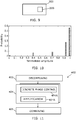
- FIG 10 is a histogram of the signal constellation points 42 at any antenna 150.
- the outer, greater magnitude, constellation points 142 from outphasing are selected more often when compared with the inner constellation points.
- the outer constellation points have higher output power, and therefore higher efficiency than the inner constellation points.
- the multiple amplifiers 114 n are constant-envelope and therefore consume a fixed amount of power. Decreasing output power, while keeping the power consumed fixed reduces efficiency
- FIG 11 illustrates an example of a method 400 as previously described.
- the method comprises:
- the separate discrete phase control 404A and amplification 404B of each of the constant-envelope components ⁇ Sn ⁇ can occur contemporaneously in parallel.
- circuitry may refer to one or more or all of the following:
- circuitry also covers an implementation of merely a hardware circuit or processor and its (or their) accompanying software and/or firmware.
- circuitry also covers, for example and if applicable to the particular claim element, a baseband integrated circuit for a mobile device or a similar integrated circuit in a server, a cellular network device, or other computing or network device.
- the blocks illustrated in the Fig 11 may represent steps in a method and/or sections of code in a computer program.
- the illustration of a particular order to the blocks does not necessarily imply that there is a required or preferred order for the blocks and the order and arrangement of the block may be varied. Furthermore, it may be possible for some blocks to be omitted.
- the precedingly described apparatus 100, system 200 and base station 300 comprise:
- a property of the instance can be a property of only that instance or a property of the class or a property of a sub-class of the class that includes some but not all of the instances in the class. It is therefore implicitly disclosed that a feature described with reference to one example but not with reference to another example, can where possible be used in that other example as part of a working combination but does not necessarily have to be used in that other example.
- 'a' or 'the' is used in this document with an inclusive not an exclusive meaning. That is any reference to X comprising a/the Y indicates that X may comprise only one Y or may comprise more than one Y unless the context clearly indicates the contrary. If it is intended to use 'a' or 'the' with an exclusive meaning then it will be made clear in the context. In some circumstances the use of 'at least one' or 'one or more' may be used to emphasis an inclusive meaning but the absence of these terms should not be taken to infer and exclusive meaning.
- the presence of a feature (or combination of features) in a claim is a reference to that feature or (combination of features) itself and also to features that achieve substantially the same technical effect (equivalent features).
- the equivalent features include, for example, features that are variants and achieve substantially the same result in substantially the same way.
- the equivalent features include, for example, features that perform substantially the same function, in substantially the same way to achieve substantially the same result.
Landscapes
- Engineering & Computer Science (AREA)
- Power Engineering (AREA)
- Computer Networks & Wireless Communication (AREA)
- Signal Processing (AREA)
- Transmitters (AREA)
- Radio Transmission System (AREA)
Priority Applications (3)
| Application Number | Priority Date | Filing Date | Title |
|---|---|---|---|
| EP20160345.3A EP3876420B1 (fr) | 2020-03-02 | 2020-03-02 | Transmission de fréquence radio |
| US17/183,772 US11546202B2 (en) | 2020-03-02 | 2021-02-24 | Radio frequency transmission |
| CN202110226381.5A CN113346845B (zh) | 2020-03-02 | 2021-03-01 | 射频传输 |
Applications Claiming Priority (1)
| Application Number | Priority Date | Filing Date | Title |
|---|---|---|---|
| EP20160345.3A EP3876420B1 (fr) | 2020-03-02 | 2020-03-02 | Transmission de fréquence radio |
Publications (2)
| Publication Number | Publication Date |
|---|---|
| EP3876420A1 true EP3876420A1 (fr) | 2021-09-08 |
| EP3876420B1 EP3876420B1 (fr) | 2025-06-18 |
Family
ID=69743102
Family Applications (1)
| Application Number | Title | Priority Date | Filing Date |
|---|---|---|---|
| EP20160345.3A Active EP3876420B1 (fr) | 2020-03-02 | 2020-03-02 | Transmission de fréquence radio |
Country Status (3)
| Country | Link |
|---|---|
| US (1) | US11546202B2 (fr) |
| EP (1) | EP3876420B1 (fr) |
| CN (1) | CN113346845B (fr) |
Citations (4)
| Publication number | Priority date | Publication date | Assignee | Title |
|---|---|---|---|---|
| WO2001091282A2 (fr) * | 2000-05-26 | 2001-11-29 | D.S.P.C. Technologies Ltd. | Amplificateur de puissance rf et procedes permettant d'ameliorer l'efficacite de celui-ci |
| WO2008147908A1 (fr) * | 2007-05-25 | 2008-12-04 | Rambus Inc. | Système de formation de faisceau multi-antennes pour transmettre des signaux d'enveloppe constants décomposés à partir d'un signal d'enveloppe variable |
| US20100074367A1 (en) * | 2008-09-19 | 2010-03-25 | Samsung Electro-Mechanics Company, Ltd. | Adaptive combiner error calibration algorithms in all-digital outphasing transmitter |
| US20150180692A1 (en) * | 2013-12-20 | 2015-06-25 | Texas Instruments Incorporated | Circuits and methods for transmitting signals |
Family Cites Families (12)
| Publication number | Priority date | Publication date | Assignee | Title |
|---|---|---|---|---|
| SE521746C2 (sv) * | 2002-04-05 | 2003-12-02 | Ericsson Telefon Ab L M | Multimoduleringssändare |
| US8482462B2 (en) * | 2007-05-25 | 2013-07-09 | Rambus Inc. | Multi-antenna beam-forming system for transmitting constant envelope signals decomposed from a variable envelope signal |
| US8824984B2 (en) * | 2012-06-29 | 2014-09-02 | Intel Corporation | Outphasing power combining by antenna |
| US9137067B1 (en) * | 2013-12-17 | 2015-09-15 | Rockwell Collins, Inc. | High efficiency outphasing transmitter for electronically scanned arrays |
| US9197241B2 (en) | 2013-12-20 | 2015-11-24 | Nokia Technologies Oy | Output power control for RF digital-to-analog converter |
| US10193508B2 (en) | 2014-04-17 | 2019-01-29 | Texas Instruments Incorporated | Multi-branch outphasing system and method |
| EP3206300B1 (fr) * | 2016-02-09 | 2018-09-26 | Nxp B.V. | Amplificateur de déphasage |
| US10142136B1 (en) * | 2016-05-09 | 2018-11-27 | L3 Technologies Inc. | Self-consistent outphasing signal separation |
| CN106102156A (zh) * | 2016-05-30 | 2016-11-09 | 成都理工大学 | 基于多天线的线性化传输方法 |
| US9954706B1 (en) * | 2016-10-28 | 2018-04-24 | L3 Technologies Inc. | Outphased spatial combiner |
| US10069467B1 (en) * | 2017-03-01 | 2018-09-04 | Paulo Carvalho | Apparatus for quantized linear amplification with nonlinear amplifiers |
| US10938347B2 (en) * | 2019-06-24 | 2021-03-02 | Silicon Valley Bank | Outphasing power combiner |
-
2020
- 2020-03-02 EP EP20160345.3A patent/EP3876420B1/fr active Active
-
2021
- 2021-02-24 US US17/183,772 patent/US11546202B2/en active Active
- 2021-03-01 CN CN202110226381.5A patent/CN113346845B/zh active Active
Patent Citations (4)
| Publication number | Priority date | Publication date | Assignee | Title |
|---|---|---|---|---|
| WO2001091282A2 (fr) * | 2000-05-26 | 2001-11-29 | D.S.P.C. Technologies Ltd. | Amplificateur de puissance rf et procedes permettant d'ameliorer l'efficacite de celui-ci |
| WO2008147908A1 (fr) * | 2007-05-25 | 2008-12-04 | Rambus Inc. | Système de formation de faisceau multi-antennes pour transmettre des signaux d'enveloppe constants décomposés à partir d'un signal d'enveloppe variable |
| US20100074367A1 (en) * | 2008-09-19 | 2010-03-25 | Samsung Electro-Mechanics Company, Ltd. | Adaptive combiner error calibration algorithms in all-digital outphasing transmitter |
| US20150180692A1 (en) * | 2013-12-20 | 2015-06-25 | Texas Instruments Incorporated | Circuits and methods for transmitting signals |
Also Published As
| Publication number | Publication date |
|---|---|
| US11546202B2 (en) | 2023-01-03 |
| US20210273841A1 (en) | 2021-09-02 |
| CN113346845B (zh) | 2025-07-11 |
| CN113346845A (zh) | 2021-09-03 |
| EP3876420B1 (fr) | 2025-06-18 |
Similar Documents
| Publication | Publication Date | Title |
|---|---|---|
| EP1451925B1 (fr) | Amplificateur composite | |
| EP3488531B1 (fr) | Prédistorsion numérique pour systèmes à antennes multiples | |
| US10367535B2 (en) | Cartesian loop circuits, transmitters, devices, and related methods | |
| US9071207B2 (en) | Predistortion of concurrent multi-band signal to compensate for PA non-linearity | |
| CN102082752B (zh) | 一种数字预失真处理方法及设备 | |
| US7336753B2 (en) | Transmitter | |
| US7986738B2 (en) | Peak to average power ratio reduction apparatus and method for a wireless OFDM transmitter | |
| US7565119B2 (en) | Predistortion correction loop-back based on high linearity and low linearity modes | |
| US20040136470A1 (en) | Uncorrelated adaptive predistorter | |
| EP0648012A1 (fr) | Commande de puissance pour amplificateurs cartésiens | |
| US20030125065A1 (en) | Method and apparatus for generating an output signal | |
| Zhang et al. | Calibration scheme for LINC transmitter | |
| US20110111711A1 (en) | High Efficiency Linear Transmitter | |
| US20190131933A1 (en) | Power Amplifier System and Learning-based Autotuning Method Thereof | |
| US20130243125A1 (en) | Transmission apparatus and transmission method | |
| US7496333B2 (en) | Transmission circuit and communication apparatus employing the same | |
| US8155237B2 (en) | Multi-carrier transmitter | |
| US9184699B2 (en) | Variable-size mixer for high gain range transmitter | |
| US9137082B1 (en) | System and method for joint compensation of power amplifier's distortion | |
| Tahkoubit et al. | Generalized iterative dichotomy PAPR reduction method for multicarrier waveforms | |
| CN103518331A (zh) | 发射机和用于信号发射的方法 | |
| US11546202B2 (en) | Radio frequency transmission | |
| US7570711B1 (en) | Quadrature LINC transmission method and apparatus | |
| Lu et al. | In-band digital predistortion for concurrent dual-broadband phased array transmitters | |
| EP2685690B1 (fr) | Technique permettant de générer un signal de fréquence radio sur la base d'un signal de compensation de décalage |
Legal Events
| Date | Code | Title | Description |
|---|---|---|---|
| PUAI | Public reference made under article 153(3) epc to a published international application that has entered the european phase |
Free format text: ORIGINAL CODE: 0009012 |
|
| STAA | Information on the status of an ep patent application or granted ep patent |
Free format text: STATUS: THE APPLICATION HAS BEEN PUBLISHED |
|
| AK | Designated contracting states |
Kind code of ref document: A1 Designated state(s): AL AT BE BG CH CY CZ DE DK EE ES FI FR GB GR HR HU IE IS IT LI LT LU LV MC MK MT NL NO PL PT RO RS SE SI SK SM TR |
|
| STAA | Information on the status of an ep patent application or granted ep patent |
Free format text: STATUS: REQUEST FOR EXAMINATION WAS MADE |
|
| STAA | Information on the status of an ep patent application or granted ep patent |
Free format text: STATUS: EXAMINATION IS IN PROGRESS |
|
| 17P | Request for examination filed |
Effective date: 20220308 |
|
| RBV | Designated contracting states (corrected) |
Designated state(s): AL AT BE BG CH CY CZ DE DK EE ES FI FR GB GR HR HU IE IS IT LI LT LU LV MC MK MT NL NO PL PT RO RS SE SI SK SM TR |
|
| 17Q | First examination report despatched |
Effective date: 20220322 |
|
| REG | Reference to a national code |
Ref country code: DE Ref legal event code: R079 Free format text: PREVIOUS MAIN CLASS: H03F0001020000 Ipc: H03F0003240000 Ref country code: DE Ref legal event code: R079 Ref document number: 602020052817 Country of ref document: DE Free format text: PREVIOUS MAIN CLASS: H03F0001020000 Ipc: H03F0003240000 |
|
| GRAP | Despatch of communication of intention to grant a patent |
Free format text: ORIGINAL CODE: EPIDOSNIGR1 |
|
| STAA | Information on the status of an ep patent application or granted ep patent |
Free format text: STATUS: GRANT OF PATENT IS INTENDED |
|
| RIC1 | Information provided on ipc code assigned before grant |
Ipc: H03F 3/217 20060101ALI20240731BHEP Ipc: H03F 3/21 20060101ALI20240731BHEP Ipc: H03F 3/19 20060101ALI20240731BHEP Ipc: H03F 1/02 20060101ALI20240731BHEP Ipc: H03F 3/24 20060101AFI20240731BHEP |
|
| INTG | Intention to grant announced |
Effective date: 20240814 |
|
| GRAJ | Information related to disapproval of communication of intention to grant by the applicant or resumption of examination proceedings by the epo deleted |
Free format text: ORIGINAL CODE: EPIDOSDIGR1 |
|
| STAA | Information on the status of an ep patent application or granted ep patent |
Free format text: STATUS: EXAMINATION IS IN PROGRESS |
|
| GRAP | Despatch of communication of intention to grant a patent |
Free format text: ORIGINAL CODE: EPIDOSNIGR1 |
|
| STAA | Information on the status of an ep patent application or granted ep patent |
Free format text: STATUS: GRANT OF PATENT IS INTENDED |
|
| INTC | Intention to grant announced (deleted) | ||
| INTG | Intention to grant announced |
Effective date: 20250109 |
|
| GRAS | Grant fee paid |
Free format text: ORIGINAL CODE: EPIDOSNIGR3 |
|
| GRAA | (expected) grant |
Free format text: ORIGINAL CODE: 0009210 |
|
| STAA | Information on the status of an ep patent application or granted ep patent |
Free format text: STATUS: THE PATENT HAS BEEN GRANTED |
|
| AK | Designated contracting states |
Kind code of ref document: B1 Designated state(s): AL AT BE BG CH CY CZ DE DK EE ES FI FR GB GR HR HU IE IS IT LI LT LU LV MC MK MT NL NO PL PT RO RS SE SI SK SM TR |
|
| REG | Reference to a national code |
Ref country code: GB Ref legal event code: FG4D |
|
| REG | Reference to a national code |
Ref country code: CH Ref legal event code: EP |
|
| REG | Reference to a national code |
Ref country code: DE Ref legal event code: R096 Ref document number: 602020052817 Country of ref document: DE |
|
| REG | Reference to a national code |
Ref country code: CH Ref legal event code: EP |
|
| REG | Reference to a national code |
Ref country code: IE Ref legal event code: FG4D |
|
| PG25 | Lapsed in a contracting state [announced via postgrant information from national office to epo] |
Ref country code: FI Free format text: LAPSE BECAUSE OF FAILURE TO SUBMIT A TRANSLATION OF THE DESCRIPTION OR TO PAY THE FEE WITHIN THE PRESCRIBED TIME-LIMIT Effective date: 20250618 |
|
| REG | Reference to a national code |
Ref country code: LT Ref legal event code: MG9D |
|
| PG25 | Lapsed in a contracting state [announced via postgrant information from national office to epo] |
Ref country code: NO Free format text: LAPSE BECAUSE OF FAILURE TO SUBMIT A TRANSLATION OF THE DESCRIPTION OR TO PAY THE FEE WITHIN THE PRESCRIBED TIME-LIMIT Effective date: 20250918 Ref country code: GR Free format text: LAPSE BECAUSE OF FAILURE TO SUBMIT A TRANSLATION OF THE DESCRIPTION OR TO PAY THE FEE WITHIN THE PRESCRIBED TIME-LIMIT Effective date: 20250919 |
|
| PG25 | Lapsed in a contracting state [announced via postgrant information from national office to epo] |
Ref country code: BG Free format text: LAPSE BECAUSE OF FAILURE TO SUBMIT A TRANSLATION OF THE DESCRIPTION OR TO PAY THE FEE WITHIN THE PRESCRIBED TIME-LIMIT Effective date: 20250618 |
|
| PG25 | Lapsed in a contracting state [announced via postgrant information from national office to epo] |
Ref country code: HR Free format text: LAPSE BECAUSE OF FAILURE TO SUBMIT A TRANSLATION OF THE DESCRIPTION OR TO PAY THE FEE WITHIN THE PRESCRIBED TIME-LIMIT Effective date: 20250618 |
|
| PG25 | Lapsed in a contracting state [announced via postgrant information from national office to epo] |
Ref country code: RS Free format text: LAPSE BECAUSE OF FAILURE TO SUBMIT A TRANSLATION OF THE DESCRIPTION OR TO PAY THE FEE WITHIN THE PRESCRIBED TIME-LIMIT Effective date: 20250918 |
|
| REG | Reference to a national code |
Ref country code: NL Ref legal event code: MP Effective date: 20250618 |
|
| PG25 | Lapsed in a contracting state [announced via postgrant information from national office to epo] |
Ref country code: LV Free format text: LAPSE BECAUSE OF FAILURE TO SUBMIT A TRANSLATION OF THE DESCRIPTION OR TO PAY THE FEE WITHIN THE PRESCRIBED TIME-LIMIT Effective date: 20250618 |
|
| PG25 | Lapsed in a contracting state [announced via postgrant information from national office to epo] |
Ref country code: NL Free format text: LAPSE BECAUSE OF FAILURE TO SUBMIT A TRANSLATION OF THE DESCRIPTION OR TO PAY THE FEE WITHIN THE PRESCRIBED TIME-LIMIT Effective date: 20250618 |
|
| PG25 | Lapsed in a contracting state [announced via postgrant information from national office to epo] |
Ref country code: PT Free format text: LAPSE BECAUSE OF FAILURE TO SUBMIT A TRANSLATION OF THE DESCRIPTION OR TO PAY THE FEE WITHIN THE PRESCRIBED TIME-LIMIT Effective date: 20251020 |
|
| REG | Reference to a national code |
Ref country code: AT Ref legal event code: MK05 Ref document number: 1805149 Country of ref document: AT Kind code of ref document: T Effective date: 20250618 |
|
| PG25 | Lapsed in a contracting state [announced via postgrant information from national office to epo] |
Ref country code: IS Free format text: LAPSE BECAUSE OF FAILURE TO SUBMIT A TRANSLATION OF THE DESCRIPTION OR TO PAY THE FEE WITHIN THE PRESCRIBED TIME-LIMIT Effective date: 20251018 |
|
| PG25 | Lapsed in a contracting state [announced via postgrant information from national office to epo] |
Ref country code: AT Free format text: LAPSE BECAUSE OF FAILURE TO SUBMIT A TRANSLATION OF THE DESCRIPTION OR TO PAY THE FEE WITHIN THE PRESCRIBED TIME-LIMIT Effective date: 20250618 Ref country code: SM Free format text: LAPSE BECAUSE OF FAILURE TO SUBMIT A TRANSLATION OF THE DESCRIPTION OR TO PAY THE FEE WITHIN THE PRESCRIBED TIME-LIMIT Effective date: 20250618 |
|
| PG25 | Lapsed in a contracting state [announced via postgrant information from national office to epo] |
Ref country code: CZ Free format text: LAPSE BECAUSE OF FAILURE TO SUBMIT A TRANSLATION OF THE DESCRIPTION OR TO PAY THE FEE WITHIN THE PRESCRIBED TIME-LIMIT Effective date: 20250618 |
|
| PG25 | Lapsed in a contracting state [announced via postgrant information from national office to epo] |
Ref country code: PL Free format text: LAPSE BECAUSE OF FAILURE TO SUBMIT A TRANSLATION OF THE DESCRIPTION OR TO PAY THE FEE WITHIN THE PRESCRIBED TIME-LIMIT Effective date: 20250618 |
|
| PG25 | Lapsed in a contracting state [announced via postgrant information from national office to epo] |
Ref country code: EE Free format text: LAPSE BECAUSE OF FAILURE TO SUBMIT A TRANSLATION OF THE DESCRIPTION OR TO PAY THE FEE WITHIN THE PRESCRIBED TIME-LIMIT Effective date: 20250618 |
|
| PG25 | Lapsed in a contracting state [announced via postgrant information from national office to epo] |
Ref country code: RO Free format text: LAPSE BECAUSE OF FAILURE TO SUBMIT A TRANSLATION OF THE DESCRIPTION OR TO PAY THE FEE WITHIN THE PRESCRIBED TIME-LIMIT Effective date: 20250618 Ref country code: SK Free format text: LAPSE BECAUSE OF FAILURE TO SUBMIT A TRANSLATION OF THE DESCRIPTION OR TO PAY THE FEE WITHIN THE PRESCRIBED TIME-LIMIT Effective date: 20250618 |
|
| PG25 | Lapsed in a contracting state [announced via postgrant information from national office to epo] |
Ref country code: ES Free format text: LAPSE BECAUSE OF FAILURE TO SUBMIT A TRANSLATION OF THE DESCRIPTION OR TO PAY THE FEE WITHIN THE PRESCRIBED TIME-LIMIT Effective date: 20250618 |
|
| REG | Reference to a national code |
Ref country code: DE Ref legal event code: R097 Ref document number: 602020052817 Country of ref document: DE |
|
| PGFP | Annual fee paid to national office [announced via postgrant information from national office to epo] |
Ref country code: GB Payment date: 20260202 Year of fee payment: 7 |
|
| PG25 | Lapsed in a contracting state [announced via postgrant information from national office to epo] |
Ref country code: DK Free format text: LAPSE BECAUSE OF FAILURE TO SUBMIT A TRANSLATION OF THE DESCRIPTION OR TO PAY THE FEE WITHIN THE PRESCRIBED TIME-LIMIT Effective date: 20250618 |
|
| PGFP | Annual fee paid to national office [announced via postgrant information from national office to epo] |
Ref country code: DE Payment date: 20260204 Year of fee payment: 7 |
|
| PG25 | Lapsed in a contracting state [announced via postgrant information from national office to epo] |
Ref country code: IT Free format text: LAPSE BECAUSE OF FAILURE TO SUBMIT A TRANSLATION OF THE DESCRIPTION OR TO PAY THE FEE WITHIN THE PRESCRIBED TIME-LIMIT Effective date: 20250618 |
|
| PLBE | No opposition filed within time limit |
Free format text: ORIGINAL CODE: 0009261 |
|
| STAA | Information on the status of an ep patent application or granted ep patent |
Free format text: STATUS: NO OPPOSITION FILED WITHIN TIME LIMIT |
|
| REG | Reference to a national code |
Ref country code: CH Ref legal event code: L10 Free format text: ST27 STATUS EVENT CODE: U-0-0-L10-L00 (AS PROVIDED BY THE NATIONAL OFFICE) Effective date: 20260430 |