EP3876504A1 - Mécanisme d'arbre rotatif, et terminal mobile - Google Patents
Mécanisme d'arbre rotatif, et terminal mobile Download PDFInfo
- Publication number
- EP3876504A1 EP3876504A1 EP19920548.5A EP19920548A EP3876504A1 EP 3876504 A1 EP3876504 A1 EP 3876504A1 EP 19920548 A EP19920548 A EP 19920548A EP 3876504 A1 EP3876504 A1 EP 3876504A1
- Authority
- EP
- European Patent Office
- Prior art keywords
- swing arm
- disposed
- connecting rod
- main shaft
- shaft assembly
- Prior art date
- Legal status (The legal status is an assumption and is not a legal conclusion. Google has not performed a legal analysis and makes no representation as to the accuracy of the status listed.)
- Granted
Links
Images








Classifications
-
- H—ELECTRICITY
- H04—ELECTRIC COMMUNICATION TECHNIQUE
- H04M—TELEPHONIC COMMUNICATION
- H04M1/00—Substation equipment, e.g. for use by subscribers
- H04M1/02—Constructional features of telephone sets
- H04M1/0202—Portable telephone sets, e.g. cordless phones, mobile phones or bar type handsets
- H04M1/0206—Portable telephones comprising a plurality of mechanically joined movable body parts, e.g. hinged housings
- H04M1/0208—Portable telephones comprising a plurality of mechanically joined movable body parts, e.g. hinged housings characterized by the relative motions of the body parts
- H04M1/0214—Foldable telephones, i.e. with body parts pivoting to an open position around an axis parallel to the plane they define in closed position
-
- H—ELECTRICITY
- H04—ELECTRIC COMMUNICATION TECHNIQUE
- H04M—TELEPHONIC COMMUNICATION
- H04M1/00—Substation equipment, e.g. for use by subscribers
- H04M1/02—Constructional features of telephone sets
- H04M1/0202—Portable telephone sets, e.g. cordless phones, mobile phones or bar type handsets
- H04M1/0206—Portable telephones comprising a plurality of mechanically joined movable body parts, e.g. hinged housings
- H04M1/0208—Portable telephones comprising a plurality of mechanically joined movable body parts, e.g. hinged housings characterized by the relative motions of the body parts
- H04M1/0214—Foldable telephones, i.e. with body parts pivoting to an open position around an axis parallel to the plane they define in closed position
- H04M1/0216—Foldable in one direction, i.e. using a one degree of freedom hinge
- H04M1/022—The hinge comprising two parallel pivoting axes
-
- H—ELECTRICITY
- H04—ELECTRIC COMMUNICATION TECHNIQUE
- H04M—TELEPHONIC COMMUNICATION
- H04M1/00—Substation equipment, e.g. for use by subscribers
- H04M1/02—Constructional features of telephone sets
- H04M1/0202—Portable telephone sets, e.g. cordless phones, mobile phones or bar type handsets
- H04M1/0206—Portable telephones comprising a plurality of mechanically joined movable body parts, e.g. hinged housings
- H04M1/0208—Portable telephones comprising a plurality of mechanically joined movable body parts, e.g. hinged housings characterized by the relative motions of the body parts
- H04M1/021—Portable telephones comprising a plurality of mechanically joined movable body parts, e.g. hinged housings characterized by the relative motions of the body parts using combined folding and rotation motions
-
- H—ELECTRICITY
- H04—ELECTRIC COMMUNICATION TECHNIQUE
- H04M—TELEPHONIC COMMUNICATION
- H04M1/00—Substation equipment, e.g. for use by subscribers
- H04M1/02—Constructional features of telephone sets
- H04M1/0202—Portable telephone sets, e.g. cordless phones, mobile phones or bar type handsets
- H04M1/0206—Portable telephones comprising a plurality of mechanically joined movable body parts, e.g. hinged housings
- H04M1/0208—Portable telephones comprising a plurality of mechanically joined movable body parts, e.g. hinged housings characterized by the relative motions of the body parts
- H04M1/0214—Foldable telephones, i.e. with body parts pivoting to an open position around an axis parallel to the plane they define in closed position
- H04M1/0216—Foldable in one direction, i.e. using a one degree of freedom hinge
-
- G—PHYSICS
- G06—COMPUTING OR CALCULATING; COUNTING
- G06F—ELECTRIC DIGITAL DATA PROCESSING
- G06F1/00—Details not covered by groups G06F3/00 - G06F13/00 and G06F21/00
- G06F1/16—Constructional details or arrangements
- G06F1/1613—Constructional details or arrangements for portable computers
- G06F1/1633—Constructional details or arrangements of portable computers not specific to the type of enclosures covered by groups G06F1/1615 - G06F1/1626
- G06F1/1637—Details related to the display arrangement, including those related to the mounting of the display in the housing
- G06F1/1641—Details related to the display arrangement, including those related to the mounting of the display in the housing the display being formed by a plurality of foldable display components
-
- G—PHYSICS
- G06—COMPUTING OR CALCULATING; COUNTING
- G06F—ELECTRIC DIGITAL DATA PROCESSING
- G06F1/00—Details not covered by groups G06F3/00 - G06F13/00 and G06F21/00
- G06F1/16—Constructional details or arrangements
- G06F1/1613—Constructional details or arrangements for portable computers
- G06F1/1633—Constructional details or arrangements of portable computers not specific to the type of enclosures covered by groups G06F1/1615 - G06F1/1626
- G06F1/1675—Miscellaneous details related to the relative movement between the different enclosures or enclosure parts
- G06F1/1681—Details related solely to hinges
-
- H—ELECTRICITY
- H05—ELECTRIC TECHNIQUES NOT OTHERWISE PROVIDED FOR
- H05K—PRINTED CIRCUITS; CASINGS OR CONSTRUCTIONAL DETAILS OF ELECTRIC APPARATUS; MANUFACTURE OF ASSEMBLAGES OF ELECTRICAL COMPONENTS
- H05K5/00—Casings, cabinets or drawers for electric apparatus
- H05K5/02—Details
- H05K5/0217—Mechanical details of casings
- H05K5/0226—Hinges
-
- G—PHYSICS
- G06—COMPUTING OR CALCULATING; COUNTING
- G06F—ELECTRIC DIGITAL DATA PROCESSING
- G06F1/00—Details not covered by groups G06F3/00 - G06F13/00 and G06F21/00
- G06F1/16—Constructional details or arrangements
- G06F1/1613—Constructional details or arrangements for portable computers
- G06F1/1633—Constructional details or arrangements of portable computers not specific to the type of enclosures covered by groups G06F1/1615 - G06F1/1626
- G06F1/1637—Details related to the display arrangement, including those related to the mounting of the display in the housing
- G06F1/1652—Details related to the display arrangement, including those related to the mounting of the display in the housing the display being flexible, e.g. mimicking a sheet of paper, or rollable
-
- H—ELECTRICITY
- H04—ELECTRIC COMMUNICATION TECHNIQUE
- H04M—TELEPHONIC COMMUNICATION
- H04M1/00—Substation equipment, e.g. for use by subscribers
- H04M1/02—Constructional features of telephone sets
- H04M1/0202—Portable telephone sets, e.g. cordless phones, mobile phones or bar type handsets
- H04M1/026—Details of the structure or mounting of specific components
- H04M1/0266—Details of the structure or mounting of specific components for a display module assembly
- H04M1/0268—Details of the structure or mounting of specific components for a display module assembly including a flexible display panel
Definitions
- This application relates to the field of mobile terminal technologies, and in particular, to a rotating shaft mechanism and a mobile terminal.
- a foldable terminal product for example, an electronic device such as a foldable mobile phone, a foldable tablet, or a foldable computer
- a foldable mobile phone is used as an example. Different from a previous flip mobile phone, because a display of a flexible foldable mobile phone is continuously foldable, to ensure that the foldable display is not pulled or squeezed, an appearance of a structural design of the product is greatly deformed at a bending part of a rotating shaft in a middle part.
- a common structure cannot achieve such a large deformation amount. Therefore, in a flexible foldable terminal product, a special hinge needs to be designed for a bent and deformed part, to meet requirements such as operation experience, an appearance, and reliability of a structural design of the product.
- thickness of a bent part of a folded hinge used in the prior art is greater than thickness of a structural design, affecting an effect of a folded terminal.
- This application provides a rotating shaft mechanism and a mobile terminal, to improve a folding effect of the mobile terminal.
- a rotating shaft mechanism is provided.
- the rotating shaft mechanism is applied to a foldable mobile terminal and is used as a folding mechanism of the mobile terminal.
- the rotating shaft mechanism is fixedly connected to two housings of the mobile terminal, and when the mobile terminal is folded, the two housings rotate around the rotating shaft mechanism to implement folding.
- the rotating shaft mechanism includes a main shaft assembly, a swing arm assemblies, and a support assembly.
- the main shaft assembly is a support piece, and the swing arm assembly is configured to connect the support assembly and the main shaft assembly. A movement manner of the support assembly is changed by using the swing arm assembly, to improve a folding effect of the mobile terminal.
- the swing arm assembly includes at least one connecting rod group and at least one swing arm group.
- Each connecting rod group includes two connecting rods that are correspondingly disposed on two sides of the main shaft assembly and that are rotatably connected to the main shaft assembly.
- Each swing arm group includes swing arms that are respectively disposed on the two sides of the main shaft assembly, and the swing arms are configured to be fixedly connected to the two housings of the mobile terminal.
- each swing arm is rotatably connected to the main shaft assembly, and an axis around which each swing arm rotates and an axis around which a corresponding connecting rod rotates are different axes, and each are parallel to a length direction of the main shaft assembly.
- Each swing arm is slidably connected to and can rotate relative to at least one connecting rod located on a same side.
- the support assembly When the swing arm assembly supports the support assembly, the support assembly includes support plates correspondingly disposed on the two sides of the main shaft assembly, and each support plate is rotatably connected to a swing arm located on a same side and is slidably connected to and can rotate relative to a connecting rod located on the same side, or each support plate is rotatably connected to the main shaft assembly, and is slidably connected to and can rotate relative to a swing arm located on a same side.
- An axis around which the support plate is rotatably connected to the swing arm or rotatably connected to the main shaft assembly is parallel to a length direction of the main shaft assembly.
- the corresponding connecting rods or the swing arms drive the two support plates to rotate to a second position in directions towards each other, and the support plates and the main shaft assembly enclose folding space for accommodating a flexible display of the mobile terminal.
- the connecting rods rotate, and the swing arms rotate relative to the main shaft assembly, so that thickness of the folded folding mechanism is approximately equal to thickness of the two stacked housings, thereby improving an effect of the folded mobile terminal.
- the support plates and the main shaft assembly enclose the space for accommodating the flexible display, thereby improving a bending effect of the flexible display.
- the axes around which the two connecting rods in each connecting rod group rotate are symmetrically disposed on two sides of the axes around which the two swing arms in the corresponding swing arm group rotate.
- a sliding direction of the connecting rod is perpendicular to an axial direction of the connecting rod, and when the swing arms located on the two sides of the main shaft assembly rotate to the first position in the directions towards each other, the corresponding connecting rods slide to positions close to the axes around which the swing arms rotate.
- the connecting rod slides towards an end that is of the swing arm and that is slidably connected to the main shaft assembly.
- first arc-shaped sliding slots in a one-to-one correspondence with the swing arms are disposed on the main shaft assembly, and first arc-shaped arms slidably assembled in the corresponding first arc-shaped sliding slots are disposed on the swing arms.
- the main shaft assembly When the main shaft assembly is specifically disposed, the main shaft assembly includes a main outer shaft and a main inner shaft fixedly connected to the main outer shaft.
- Each first arc-shaped sliding slot includes a concave arc-shaped groove disposed on the main outer shaft and an arc-shaped surface that is disposed on the main inner shaft and that covers the arc-shaped groove.
- a structure of the first arc-shaped sliding slot is implemented through assembly.
- the main shaft assembly includes a main outer shaft and a main inner shaft fixedly connected to the main outer shaft.
- the first arc-shaped sliding slots are disposed on the main inner shaft or the main outer shaft, facilitating disposing of structures of the first arc-shaped sliding slots.
- the first arc-shaped arms correspondingly disposed on the two swing arms in each swing arm group are disposed in a staggered manner, thereby increasing lengths of slidable connection parts between the swing arms and the main shaft assembly, and further improving structural stability.
- gears are respectively disposed on two opposite ends of the two connecting rods in each connecting rod group, and the two gears engage with each other.
- the two engaging gears are disposed, so that the connecting rods can move synchronously, thereby ensuring synchronization between the two housings when the mobile terminal is folded.
- a cavity for accommodating the two engaging gears is disposed in the main shaft assembly.
- the two gears are located in the cavity, and the two gears are rotatably connected to the main shaft assembly.
- Rotatable connection between the connecting rods and the main shaft assembly is implemented through rotatable connection between the two gears and the main shaft assembly.
- the main shaft assembly further includes a limiting mechanism, configured to limit relative positions at which the connecting rods rotate relative to the main shaft assembly. Rotation of the connecting rods relative to the main shaft assembly is limited by using the limiting mechanism, to limit a folded and unfolded state of the mobile terminal.
- the limiting mechanism may use different structures.
- the limiting mechanism includes a first cam that rotates synchronously with each connecting rod, and a second cam that is disposed opposite to each first cam. Protrusions and notches that engage with each other are disposed on opposite surfaces of the first cam and the second cam that are disposed opposite to each other, and one of the first cam and the second cam can slide relative to the main shaft assembly.
- the limiting mechanism further includes an elastic part configured to push the first cam or the second cam to slide towards the other corresponding cam. Rotation positions of the connecting rods and the main shaft assembly can be limited through cooperation between the protrusions and the notches on the first cam and the second cam.
- the first cam and the gear are coaxially disposed.
- the limiting mechanism further includes: a camshaft fixedly connected to each connecting rod, the camshaft penetrates the first cam and the second cam that are disposed opposite to each other, the first cam can rotate synchronously with the camshaft, and the second cam can rotate relative to the camshaft. A coaxial effect of the first cam and the second cam is ensured by using the camshaft.
- the elastic part may be a compression spring, and the camshaft penetrates the compression spring.
- the camshaft is used as a guiding structure.
- an elastic part is disposed between two second cams corresponding to any two adjacent first cams, and two ends of the elastic part press against the two second cams.
- the two second cams are driven by using the same elastic part, thereby simplifying a structure.
- the swing arm When the swing arm cooperates with the connecting rod, the swing arm may be slidably connected to one or more connecting rods.
- first sliding slots are disposed on two sides of the notch on each swing arm, and first protrusions slidably assembled in the first sliding slots are disposed on the corresponding connecting rod.
- a second sliding slot is disposed on each support plate, and a second protrusion slidably assembled in the second sliding slot is disposed on the corresponding connecting rod or swing arm.
- each support plate When the support plate is rotatably connected to the swing arm, each support plate is rotatably connected to the corresponding swing arm by using first pin shafts; or a second arc-shaped sliding slot is disposed on each support plate, and a second arc-shaped arm slidably assembled in the second arc-shaped sliding slot is disposed on a support arm corresponding to the support plate.
- the support plate may rotate relative to the swing arm in different manners.
- the main shaft assembly has a first surface and a second surface opposite to the first surface, and the first surface is a surface used to support the flexible display.
- the first surface is flush with a surface that is of the support plate and that is used to support the flexible display.
- the disposed first surface is flush with the surface that is of the support plate and that supports the flexible display, thereby improving an effect of supporting the flexible display.
- the mobile terminal further includes a flexible blocking layer.
- the flexible blocking layer is fixedly connected to the surface that is of the main shaft assembly and that faces away from the surface supporting the flexible display, and two ends of the flexible blocking layer are suspended, and are used to be inserted into the two housings of the mobile terminal.
- the flexible blocking layer can block the notches on the main shaft assembly, thereby improving an appearance effect of the mobile terminal.
- the mobile terminal further includes a flexible blocking layer.
- the flexible blocking layer is fixedly connected to the surface that is of the main shaft assembly and that faces away from the surface supporting the flexible display, at least one swing arm is rotatably connected to a swing rod, and the swing rod is slidably connected to the flexible blocking layer. Two ends of the flexible blocking layer are fixed by using the swing rod.
- the flexible blocking layer is an elastic steel plate or an elastic plastic plate.
- a mobile terminal includes the rotating shaft mechanism described in any one of the foregoing implementations, two housings, and a flexible display fixedly connected to the two housings.
- the two housings are arranged on two sides of the main shaft assembly, and each housing is fixedly connected to a swing arm located on a same side.
- corresponding connecting rods or the swing arms drive the two support plates to rotate to a second position in directions towards each other, and the support plates and the main shaft assembly enclose folding space for accommodating the flexible display of the mobile terminal.
- the connecting rods rotate, and the swing arms rotate relative to the main shaft assembly, so that thickness of a folded folding mechanism is approximately equal to thickness of the two stacked housings, thereby improving an effect of the folded mobile terminal.
- the support plates and the main shaft assembly enclose the space for accommodating the flexible display, thereby improving a bending effect of the flexible display.
- the flexible display is connected to the support plates by using adhesive.
- the flexible display is connected to the support plates by using adhesive, thereby improving a folding effect of the flexible display.
- a flexible blocking layer is inserted into the two housings.
- a folding effect of the mobile terminal is improved by using the disposed flexible blocking layer.
- the rotating shaft mechanism is applied to a mobile terminal, and particularly, to a mobile terminal whose display can be bent, for example, a mobile phone, a PDA, a notebook computer, or a tablet computer.
- the mobile terminal includes a structure shown in FIG. 1 : a left housing 20, a rotating shaft mechanism 10, a right housing 30, and a flexible display 40.
- the rotating shaft mechanism 10 is rotatably connected to the left housing 20 and the right housing 30, and the rotating shaft mechanism 10 rotates to enable the left housing 20 and the right housing 30 to rotate relative to each other.
- the flexible display 40 covers the left housing 20, the right housing 30, and the rotating shaft mechanism 10, and is separately connected to the left housing 20, the right housing 30, and the rotating shaft mechanism 10 (a connection manner may be adhesive connection or the like), to form the structure shown in FIG. 1 .
- the mobile terminal has two states: an unfolded state and a folded state.
- FIG. 1 shows the mobile terminal in the unfolded state.
- the rotating shaft mechanism 10 is unfolded
- the left housing 20 and the right housing 30 are arranged on two sides of the rotating shaft mechanism 10 and are unfolded.
- the flexible display 40 is unfolded.
- the left housing 20 and the right housing 30 rotate relative to each other, and the rotating shaft mechanism 10 rotates.
- the mobile terminal After being folded, the mobile terminal is in a state shown in FIG. 3 .
- the left housing 20 and the right housing 30 are stacked relative to each other, and the flexible display 40 is bent along with the left housing 20 and the right housing 30.
- the rotating shaft mechanism 10 provided in this embodiment of this application, the following describes a structure of the rotating shaft mechanism 10 in detail with reference to the accompanying drawings.
- FIG. 4 is a schematic structural diagram of the rotating shaft mechanism 10
- FIG. 5 is a schematic exploded diagram of the rotating shaft mechanism 10.
- the rotating shaft mechanism 10 provided in this embodiment of this application mainly includes three parts: a main shaft assembly 11, swing arm assembly, and a support assembly.
- the main shaft assembly 11 is a support piece and plays a role of a rotating shaft.
- the swing arm assembly is configured to connect the two housings of the mobile terminal, and the support assembly is configured to form a structure supporting the flexible display 40.
- the swing arm assembly is further used as connecting piece to connect the support assembly and the main shaft assembly 11.
- an overall structure of the main shaft assembly 11 provided in this embodiment of this application is a semi-cylinder, and side surfaces of the main shaft assembly 11 include a first surface and a second surface connected to the first surface.
- the first surface is a plane and is used to support the flexible display 40
- the second surface is an arc-shaped cylindrical surface.
- a length direction of the main shaft assembly 11 is defined. As shown in FIG. 2 and FIG. 3 , the length direction of the main shaft assembly 11 is a direction of axes around which the left housing 20 and the right housing 30 rotate.
- the main shaft assembly 11 may use different structures.
- the main shaft assembly 11 includes two parts, namely, a main inner shaft 112 and a main outer shaft 111, and the main inner shaft 112 is fixedly connected to the main outer shaft 111.
- the main inner shaft 112 and the main outer shaft 111 are detachably and fixedly connected by using screws.
- the main inner shaft 112 may be fixedly connected to the main outer shaft 111 by using a buckle or a rivet.
- the first surface is a surface of the main inner shaft 112
- the second surface is a surface of the main outer shaft 111.
- a split structure used by the main shaft assembly 11 is merely a specific example.
- the main shaft assembly 11 provided in this embodiment of this application may alternatively use another structure.
- a structure corresponding to the swing arm assembly is disposed on the main shaft assembly 11.
- the swing arm assembly provided in this embodiment of this application includes two main structures: a connecting rod group and a swing arm group.
- the connecting rod group is configured to connect the swing arm group and the main shaft assembly 11, and the swing arm group is configured to be connected to the housings.
- a quantity of the connecting rod groups and a quantity of the swing arm groups may be determined according to a requirement, for example, one swing arm group and one connecting rod group are disposed, or two swing arm groups and two connecting rod groups are disposed, or two swing arm groups and three connecting rod groups are disposed.
- One swing arm group may correspond to one connecting rod group, or one swing arm group may correspond to a plurality of connecting rod groups, and this may be determined according to an actual requirement during specific disposing. As shown in FIG.
- two swing arm groups and two connecting rod groups are used in the structures shown in FIG. 5 and FIG. 6 , and the swing arm groups are in a one-to-one correspondence with the connecting rod groups.
- one swing arm group may correspond to two connecting rod groups or another correspondence may be used.
- the connecting rod groups are described.
- the connecting rod groups have a same structure.
- FIG. 7 and FIG. 8 show structures of connection between the connecting rod groups in the two swing arm assemblies in FIG. 5 and the main shaft assembly 11. It can be learned from FIG. 7 and FIG. 8 that the two connecting rod groups are connected to the main shaft assembly 11 in a same manner. Therefore, one connecting rod group is used as an example.
- the connecting rod group includes two connecting rods.
- the two connecting rods are named a left connecting rod 14a and a right connecting rod 14b.
- the two connecting rods are correspondingly disposed on two sides of the main shaft assembly 11.
- the left connecting rod 14a and the right connecting rod 14b are arranged on the two sides of the main shaft assembly 11 in the length direction of the main shaft assembly 11, and are rotatably connected to the main shaft assembly 11.
- the main shaft assembly 11 includes the main outer shaft 111 and the main inner shaft 112.
- the main outer shaft 111 is an arc-shaped housing, and a groove is disposed in the arc-shaped housing.
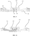
- the main inner shaft 112 When the main outer shaft 111 is fixedly connected to the main inner shaft 112, the main inner shaft 112 covers the groove to form a cavity 113 shown in FIG. 9 .
- the left connecting rod 14a and the right connecting rod 14b are separately inserted into the cavity 113.
- an end of each of the left connecting rod 14a and the right connecting rod 14b inserted into the cavity 113 is connected to a shaft 143, and the shaft 143 is rotatably connected to the main shaft assembly 11.
- grooves having a semicircular cross section are designed on each of the main inner shaft 112 and the main outer shaft 111, holes having a circular cross section are formed after the main inner shaft 112 and the main outer shaft 111 are assembled, and the holes having a circular cross section fit with the shafts 143 of the connecting rods.
- circular holes may be alternatively disposed on the main inner shaft 112 or the main outer shaft 111, so that the shafts 143 penetrate the holes.
- the connecting rod is strip-shaped.
- one end of each of the left connecting rod 14a and the right connecting rod 14b is located in the main shaft assembly 11, and the other end extends to the outside of the main shaft assembly 11.
- notches fitting with the left connecting rod 14a and the right connecting rod 14b are correspondingly disposed on the main outer shaft 111, so that the left connecting rod 14a and the right connecting rod 14b have relatively large rotation space.
- the end that is of each of the left connecting rod 14a and the right connecting rod 14b and that is exposed outside the main shaft assembly 11 is used to be slidably connected to a swing arm in the swing arm group.
- a structure of the swing arm group is described below in detail.
- the swing arm group provided in this embodiment of this application includes two swing arms.
- the two swing arms are named a left swing arm 13a and a right swing arm 13b, and the left swing arm 13a and the right swing arm 13b are configured to be fixedly connected to the two housings of the mobile terminal.
- the left swing arm 13a is fixedly connected to the left housing 20
- the right swing arm 13b is fixedly connected to the right housing 30.
- a bolt or a screw may be used for fixed connection.
- the left swing arm 13a and the right swing arm 13b move synchronously with the left housing 20 and the right housing 30, respectively.
- the left swing arm 13a and the right swing arm 13b are disposed on the two sides of the main shaft assembly 11. More specifically, the left swing arm 13a and the right swing arm 13b are arranged on the two sides of the main shaft assembly 11 in the length direction of the main shaft assembly 11. The left swing arm 13a and the right swing arm 13b are connected to the connecting rods and the main shaft assembly 11 in a same manner. Therefore, the left swing arm 13a is used as an example for description.
- the left swing arm 13a When the left swing arm 13a is specifically connected to the main shaft assembly 11, the left swing arm 13a is rotatably connected to the main shaft assembly 11. In addition, an axis around which the left swing arm 13a rotates is different from an axis around which the corresponding connecting rod rotates. Although the left swing arm 13a and the corresponding connecting rod rotate around different axes, both the axis around which the left swing arm 13a rotates and the axis around which the corresponding connecting rod rotates are parallel to the length direction of the main shaft assembly 11.
- FIG. 10 shows a specific structure of rotatable connection between the left swing arm 13a and the main shaft assembly 11.
- a first arc-shaped sliding slot 114 is disposed in the main shaft assembly 11, and the left swing arm 13a is slidably assembled in the first arc-shaped sliding slot 114.
- the left swing arm 13a slides relative to the main shaft assembly 11, the left swing arm 13a simultaneously rotates relative to the main shaft assembly 11.
- an arc-shaped surface is disposed in the main inner shaft 112, and the arc-shaped surface is a convex arc-shaped surface.
- the arc-shaped surface is opposite to the first surface of the main inner shaft 112.
- a concave arc-shaped groove is disposed on the main outer shaft 111, and the arc-shaped groove and the main outer shaft 111 are disposed on a surface opposite to the second surface.
- the arc-shaped surface covers the arc-shaped groove to form the first arc-shaped sliding slot 114.
- the first arc-shaped sliding slot 114 may be alternatively directly formed on the main outer shaft 111 or the main inner shaft 112 by using an integral structure.
- the first arc-shaped sliding slot 114 when the first arc-shaped sliding slot 114 is disposed, the first arc-shaped sliding slot may be directly fabricated on the main outer shaft 111 or the main inner shaft 112 when the main outer shaft 111 or the main inner shaft 112 is fabricated.
- precision of a sliding slot during fabrication can be improved, and it facilitates assembly of the swing arm.
- a first arc-shaped arm 132 configured to be slidably assembled in the corresponding first arc-shaped sliding slot 114 is disposed on the left swing arm 13a.
- FIG. 7 and FIG. 8 show that the first arc-shaped arm 132 is disposed on the left swing arm 13a, and one end of the first arc-shaped arm 132 is fixedly connected to one end of the left swing arm 13a.
- a quantity of corresponding first arc-shaped arms 132 of a swing arm is not limited.
- One first arc-shaped arm 132 may be disposed on one swing arm, as shown in FIG. 7 and FIG. 8 , or a plurality of first arc-shaped arms 132, for example, two, three, or four first arc-shaped arms, may be disposed on one swing arm. However, regardless of a quantity of used first arc-shaped arms 132, all the first arc-shaped arms 132 are slidably assembled in the first arc-shaped sliding slot 114. As shown in FIG. 10 , the first arc-shaped arm 132 is assembled in the first arc-shaped sliding slot 114, and a radian of the first arc-shaped arm 132 is the same as a radian of the first arc-shaped sliding slot 114.
- the left swing arm 13a slides in a length direction of the first arc-shaped sliding slot 114. Because the first arc-shaped sliding slot 114 is an arc-shaped sliding slot, during sliding, the left swing arm 13a may rotate relative to the main shaft assembly 11 in directions indicated by arrows shown in FIG. 10 . The directions are rotation directions of the left swing arm 13a. It can be learned from FIG. 10 that when the left swing arm 13a slides, the left swing arm 13a may slide in an arc-shaped direction defined by the first arc-shaped sliding slot 114, and can rotate relative to the main shaft assembly 11 while sliding. When the left swing arm 13a is fixedly connected to the left housing 20, rotation of the left swing arm 13a relative to the main shaft assembly 11 may drive the left housing 20 to rotate relative to the main shaft assembly 11, to unfold or fold the mobile terminal.
- the first arc-shaped arm 132 of the right swing arm 13b when the right swing arm 13b is specifically disposed, the first arc-shaped arm 132 may be disposed in a manner different from the manner of disposing the first arc-shaped arm 132 on the left swing arm 13a. As shown in FIG. 7 and FIG. 8 , when the left swing arm 13a and the right swing arm 13b are specifically disposed, the first arc-shaped arms 132 of the left swing arm 13a and the right swing arm 13b are staggered.
- the staggering means that there is a position difference between the first arc-shaped arms 132 correspondingly connected to the two swing arms, in an axial direction of the main shaft assembly 11.
- the first arc-shaped arm 132 of the left swing arm 13a and the first arc-shaped arm 132 of the right swing arm 13b are arranged in rows in the axial direction of the main shaft assembly 11.
- the first arc-shaped arm 132 of the left swing arm 13a may be in relatively large contact with the main shaft assembly 11, that is, a length of the first arc-shaped arm 132 extending into the first arc-shaped sliding slot 114 is relatively long.
- the left swing arm 13a shown in FIG. 10 is used as an example.
- the left swing arm 13a rotates relative to the main shaft assembly 11 by 90 degrees, and therefore drives the first arc-shaped arm 132 to rotate relative to the main shaft assembly 11 by over 90 degrees.
- a contact length between the first arc-shaped arm 132 and the main shaft assembly 11 shown in FIG. 10 is obviously greater than 90 degrees. Therefore, it is ensured that the first arc-shaped arm 132 does not slide out of the first arc-shaped sliding slot 114 in a folded state, thereby improving stability when the entire swing arm is slidably connected to the main shaft assembly 11.
- the rotating shaft mechanism 10 uses a plurality of swing arm groups, the foregoing disposing manner may also be used.
- the first arc-shaped arms 132 correspondingly disposed on the two swing arms in each swing arm group are disposed in a staggered manner.
- FIG. 10 shows only a specific implementation solution.
- the first arc-shaped arms 132 of the two swing arms may be alternatively symmetrically disposed.
- the first arc-shaped arms 132 of the left swing arm 13a and the right swing arm 13b are symmetrically disposed.
- FIG. 6 and FIG. 7 show a specific manner of connection between the swing arm and the connecting rod.
- the swing arms in the swing arm group are connected to the connecting rods in the connecting rod, the two swing arms in the swing arm group are connected to the corresponding connecting rods in a same manner. Therefore, the left swing arm 13a and the left connecting rod 14a are used as an example for description.
- FIG. 7 and FIG. 8 are schematic exploded diagrams of left swing arms 13a in different swing arm groups and left connecting rods 14a.
- first sliding slots 131 are disposed on the left swing arm 13a
- first protrusions 141 are disposed on the left connecting rod 14a.
- the first protrusions 141 slide in the first sliding slots 131, to implement slidable connection between the left swing arm 13a and the left connecting rod 14a.
- the first protrusions 141 may rotate relative to the first sliding slots 131, so that the left swing arm 13a and the left connecting rod 14a rotate when sliding relative to each other.
- a notch (not marked in the figure) is disposed on the left swing arm 13a, and when the left connecting rod 14a is connected to the left swing arm 13a, the left connecting rod 14a is at least partially located in the notch on the left swing arm 13a. Disposing the notch can effectively reduce thickness of the main shaft assembly 11 after assembly, facilitating fitting with the flexible display 40 of the mobile terminal.
- the notch may be formed when the left swing arm 13a is fabricated.
- a notch may be directly fabricated on the left swing arm 13a.
- the notch may be directly formed when the left swing arm 13a is fabricated, or the notch may be formed by using a tool after the left swing arm 13a is fabricated.
- the swing arm may be alternatively of an assembly structure.
- a structure of the swing arm includes two parts: a first portion and a second portion. The first portion is connected to the first arc-shaped arm 132, the first portion is strip-shaped, and the second portion is 7-shaped. During connection, the first portion is connected to a horizontal part of the second portion, so that a notch is formed between the first portion and a vertical part of the second portion.
- first sliding slots 131 and the first protrusions 141 are specifically disposed, there are two first sliding slots 131, and the two first sliding slots 131 are disposed on two opposite side walls of the notch on the swing arm.
- the first sliding slot 131 may be a line groove or an arc-shaped groove, and may be disposed according to a requirement during specific disposing.
- the first sliding slot 131 in FIG. 8 is a line groove.
- a manner of connection between the right swing arm 13b and the right connecting rod 14b is the same as the manner of connection between the left swing arm 13a and the left connecting rod 14a. Therefore, details are not described herein again.
- the two swing arms in each swing arm group may be rotatably connected to the main shaft assembly around a same axis or around different axes. Axes around which the two connecting rods in each connecting rod group rotate are symmetrically disposed on two sides of the axes around which the two swing arms in the corresponding swing arm group rotate. Referring to FIG. 9 and FIG. 10 together, as shown in FIG.
- the axes around which the swing arms rotate are virtual axes and are located outside the first surface.
- the shafts 143 around which the connecting rods rotate are located in the main shaft assembly 11. Therefore, shafts around which the swing arms rotate are located above the shafts around which the connecting rods rotate, and the shafts 143 corresponding to the two connecting rods are symmetrically located on two sides of the axes around which the swing arms rotate.
- notches in a one-to-one correspondence with the corresponding connecting rods are disposed on the swing arms, and the connecting rods are at least partially located in the corresponding notches.
- the first sliding slots 131 are disposed, the first sliding slots 131 are disposed on two sides of the notch on each corresponding swing arm.
- the first protrusions 141 slidably assembled in the first sliding slots 131 are disposed on the corresponding connecting rod, to implement slidable connection between the swing arm and the corresponding connecting rod.
- a sliding direction of the connecting rod is perpendicular to an axial direction of the connecting rod.
- the swing arms located on the two sides of the main shaft assembly 11 rotate to a first position in directions towards each other, the two swing arms are relatively close to each other, and the mobile terminal is in the folded state.
- the corresponding connecting rods slide to positions close to the axes around which the swing arms rotate.
- the swing arms located on the two sides of the main shaft assembly 11 rotate in opposite directions to the unfolded state, the two swing arms are arranged on the two sides of the main shaft assembly 11, and the connecting rods slide, relative to the corresponding swing arms, to ends of the swing arms away from the main shaft assembly 11.
- each swing arm corresponds to one connecting rod in FIG. 7 and FIG. 8
- a quantity of swing arms and a quantity of corresponding connecting rods are not limited, for example, each swing arm corresponds to two, three, four, or another different quantity of connecting rods.
- any solution can be applied to this embodiment of this application provided that each swing arm is slidably connected to at least one connecting rod located on a same side.
- gears 142 are respectively disposed on opposite ends of the two connecting rods in each connecting rod group. Still referring to FIG. 7 and FIG. 9 , one gear 142 is disposed on each of opposite ends of the left connecting rod 14a and the right connecting rod 14b.
- a gear 142 is disposed on each of an end of the left connecting rod 14a and an end of the right connecting rod 14b that are located in the cavity 113, and the two gears 142 engage with each other when the left connecting rod 14a and the right connecting rod 14b are assembled.
- the two gears 142 are located in the cavity 113, and the shafts around which the left connecting rod 14a and the right connecting rod 14b rotate relative to the main shaft assembly 11 respectively penetrate the two gears 142.
- the engaging gears 142 drive the other connecting rod to rotate, to implement synchronous rotation between the left connecting rod 14a and the right connecting rod 14b. Further, the left connecting rod 14a and the right connecting rod 14b drive, by using the swing arm group, the two housings to be unfolded or folded synchronously.
- a limiting mechanism 18 is disposed for relative rotation between the left housing 20 and the right housing 30.
- relative positions at which the connecting rods rotate relative to the main shaft assembly 11 are limited, and positions at which the left connecting rod 14a and the right connecting rod 14b rotate relative to each other may be limited by using the limiting mechanism 18, to further limit relative positions of the left housing 20 and the right housing 30 of the mobile terminal.
- relative positions at which the swing arms rotate relative to the main shaft assembly 11 may be limited.
- positions at which the left swing arm 13a and the right swing arm 13b rotate relative to each other are limited, to further limit a relative position relationship between the left housing 20 and the right housing 30.
- the limiting mechanism is specifically disposed, different structures may be used. The following describes the structures with reference to the accompanying drawings.
- FIG. 11 shows a cooperation relationship between the limiting mechanism 18 and the connecting rods
- FIG. 12 is a schematic exploded diagram of the limiting mechanism 18 and the connecting rods.
- the limiting mechanism 18 includes a first cam 181 that rotates synchronously with each connecting rod, and a second cam 182 disposed opposite to each first cam 181. Protrusions and notches that engage with each other are disposed on opposite sides of the first cam 181 and the second cam 182 that are disposed opposite to each other.
- first cam 181 and the second cam 182 When the first cam 181 and the second cam 182 are disposed, one of the first cam 181 and the second cam 182 may slide relative to the main shaft assembly 11, to implement engaging and disengaging between the notches and the protrusions.
- both the first cam 181 and the second cam 182 may slide, or the second cam 182 may be fixed while the first cam 181 may slide, or both the first cam 181 and the second cam 182 may slide.
- the first cam 181 and the second cam 182 are specifically disposed, as shown in FIG. 11 and FIG. 12 , the first cam 181 and the corresponding gear 142 are coaxially disposed.
- the gear 142 and the corresponding cam are specifically coaxially disposed, the gear 142 of each connecting rod is coaxially and fixedly connected to one camshaft 183, and the camshaft 183 is a shaft around which the connecting rod rotates.
- the camshaft 183 penetrates the first cam 181 and the second cam 182 that are disposed opposite to each other, and the first cam 181 can rotate synchronously with the camshaft 183.
- the camshaft 183 uses a rectangular shaft, and correspondingly, a flat hole corresponding to the rectangular shaft is correspondingly disposed on the second cam 182, so that when the camshaft 183 rotates, the first cam 181 can rotate synchronously with the gear 142, and the second cam 182 can rotate relative to the camshaft 183.
- the camshaft 183 is a rectangular shaft, a through hole that the camshaft 183 penetrates is disposed on the second cam 182. Therefore, the second cam 182 can rotate relative to the camshaft 183.
- the second cam 182 is fixed (cannot rotate) relative to the main shaft assembly 11.
- the protrusions and the notches on the first cam 181 may continuously fit with the protrusions and the notches on the second gear 142, to implement limitation at different positions.
- the camshaft is disposed on the end that is of the connecting rod and that is located inside the main shaft assembly 11.
- an elastic part is used for implementation.
- the elastic part may be specifically a compression spring 184 or elastic rubber. In the structure shown in FIG. 11 , the compression spring 184 is used as the elastic part.
- the compression spring 184 is sleeved on the camshaft 183, and a limiting sheet or a limiting snap ring 185 is disposed on one end of the camshaft 183, two ends of the compression spring 184 press against the first cam 181 and the limiting sheet or the limiting snap ring 185.
- the gear 142 rotates
- the first cam 181 is driven to rotate
- the disposed compression spring 184 pushes the first cam 181 to press against the second cam 182, so that the first cam 181 and the second cam 182 rotate relative to each other.
- FIG. 11 in positions of the first cam 181 and the second cam 182 shown in FIG.
- the first cam 181 is away from the gear 142, and the second cam 182 is close to the gear 142.
- a relative position relationship between the first cam 181 and the second cam 182 is not limited to that shown in FIG. 11 .
- the first cam 181 may be close to the gear 142, and the second cam 182 may be away from the gear 142.
- FIG. 13 shows another limiting mechanism 18.
- One pair of first cam 181 and second cam 182 is added in the limiting mechanism 18.
- cooperation between two pairs of first cams 181 and second cams 182 is used in the limiting mechanism 18 shown in FIG. 13 .
- a manner of cooperation between each pair of the first cam 181 and the second cam 182 is the same as the manner shown in FIG. 11 . Therefore, details are not described herein again.
- two ends of the compression spring 184 are disposed between the two first cams 181.
- the second cams 182 need to be fixed relative to the main shaft assembly 11.
- the second cams 182 may be disposed in different manners. As shown in FIG. 11 and FIG. 12 , the two second cams 182 use an integral structure, so that when the camshafts 183 rotate, the second cams 182 do not rotate relative to the main shaft assembly 11.
- the two second cams 182 are separately disposed, but corresponding grooves are disposed inside the main shaft assembly 11 to fix the two second cams 182. In this manner, the second cams 182 can also be fixed relative to the main shaft assembly 11.
- positions of the housings of the mobile terminal may be alternatively limited by limiting rotation of the swing arms.
- the staggered first arc-shaped arms 132 are used between the left swing arm 13a and the right swing arm 13b
- the two first arc-shaped arms 132 have two opposite surfaces, and an elastic protrusion and a slot may be respectively disposed on the two surfaces.
- the disposed elastic protrusion and slot cooperate with each other, to limit rotation positions of the two swing arms, and play a limiting role. It should be understood that cooperation between the elastic protrusion and the slot is a common engaging manner in the field, and therefore a structure thereof is not described in detail.
- each connecting rod group corresponds to one pair of the first cam 181 and the second cam 182 for limiting.
- one elastic part may be used to provide an elastic force needed by the first cam 181.
- an elastic part is disposed between two second cams 182 corresponding to any two adjacent first cams 181, and two ends of the elastic part press against the two second cams 182.
- two ends of the elastic part specifically press against the two first cams 181.
- Whether the elastic part specifically presses against the first cams 181 or the second cams 182 may be determined based on actual positions for disposing the cams, so that a quantity of used elastic parts can be reduced, to simplify an entire mechanism.
- first cams 181 and the second cams 182 can limit the rotation positions of the swing arms, and a damping function is implemented through cooperation between the disposed first cams 181 and second cams 182.
- a damping force in a process of folding the mobile terminal can be increased, to provide an adjustable damping force or better folding operation experience.
- the support assembly when the rotating shaft mechanism 10 supports the flexible display 40, the flexible display 40 is supported by using the support assembly, thereby improving an effect of supporting the flexible display 40.
- the support assembly is specifically disposed, referring to FIG. 5 , the support assembly includes two support plates, and the two support plates are correspondingly disposed on the two sides of the main shaft assembly 11. To be specific, the two support plates are disposed on the two sides of the main shaft assembly 11 in the length direction of the main shaft assembly 11. As shown in FIG. 4 , when the main shaft assembly 11 has the first surface and the second surface opposite to the first surface, the first surface is a surface used to support the flexible display 40, and the support plate also has a surface used to support the flexible display 40.
- the rotating shaft mechanism When the support plates rotate to a particular position, for example, a position shown in FIG. 2 , the rotating shaft mechanism is unfolded and can support the flexible display.
- the first surface is approximately flush with the surface that is of the support plate and that is used to support the flexible display 40, so that the flexible display 40 can be evenly supported.
- Being approximately flush means that the first surface is flush with the surface that is of the support plate and that supports the flexible display 40, or there is a particular error between the first surface and the surface.
- the disposed first surface is flush with the surface that is of the support plate and that supports the flexible display 40, thereby improving an effect of supporting the flexible display 40.
- the support plates are divided into a left support plate 12a and a right support plate 12b.
- the left support plate 12a is correspondingly connected to the left swing arm 13a and the left connecting rod 14a that are on a left side
- the right support plate 12b is connected to the corresponding right swing arm 13b and right connecting rod 14b.
- different disposing manners may be used, and the following separately describes the manners with reference to the accompanying drawings.
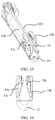
- FIG. 15 and FIG. 16 show a specific connection manner.
- a connection manner of the left support plate 12a is the same as a connection manner of the right support plate 12b. Therefore, the left support plate 12a is used as an example for description.
- the left support plate 12a is rotatably connected to the left swing arm 13a.
- the left support plate 12a is rotatably connected to the left swing arm 13a by using first pin shafts 16. Referring to FIG. 5 together, two ends on a left side of the left support plate 12a (a placement direction of the left support plate 12a in FIG.
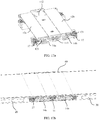
- FIG. 17a shows a specific manner of connection between the left support plate 12a and the left connecting rods 14a.
- a second sliding slot 121 is disposed on the left support plate 12a, a second protrusion is disposed on the corresponding left connecting rod 14a, and the second protrusion is slidably assembled in the second sliding slot 121.
- FIG. 17a and FIG. 17b show states of the support plates, the swing arms, and the connecting rods of the rotating shaft mechanism when the mobile terminal is in the unfolded state.
- the left support plate 12a is flush with the first surface
- the second pin shaft 17 on the left connecting rod 14a is located on a left side of the second sliding slot 121.
- the left housing 20, the rotating shaft mechanism 10, and the right housing 30 are sequentially unfolded, and the flexible display 40 covering the left housing 20, the rotating shaft mechanism 10, and the right housing 30 is unfolded.
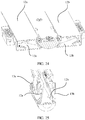
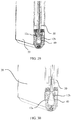
- FIG. 18 FIG.
- FIG. 18 shows a state when the rotating shaft mechanism 10 rotates to a particular angle.
- the left connecting rod 14a and the left swing arm 13a rotate relative to the main shaft assembly 11.
- the left connecting rod 14a and the left swing arm 13a slide and rotate relative to each other.
- the second pin shaft 17 slides to a position in the middle of the second sliding slot 121, and the second pin shaft 17 drives the left support plate 12a to rotate towards the left swing arm 13a.
- the second pin shaft 17 is located on a rightmost end of the second sliding slot 121, and when the left support plate 12a and the left swing arm 13a are driven by the second pin shaft 17, the left support plate 12a and the left swing arm 13a are close to each other or there is a relatively small gap between the left support plate 12a and the left swing arm 13a.
- the swing arms located on the two sides of the main shaft assembly 11 rotate to the first position in the directions towards each other
- the corresponding connecting rods and the swing arms drive the two support plates to rotate to a second position in directions towards each other
- the support plates and the main shaft assembly enclose folding space for accommodating the flexible display of the mobile terminal.
- the support plates and the main inner shaft 112 enclose space similar to a triangle.
- FIG. 19b when the flexible display 40 is folded, a folded area of the flexible display 40 forms a bend similar to a droplet shape.
- connection manner of the right support plate 12b is the same as the foregoing connection manner of the left support plate 12a. Therefore, details are not described herein again.
- the left connecting rod 14a and the right connecting rod 14b in the disposed connecting rod group drive the left support plate 12a and the right support plate 12b to move. Because the axis around which the connecting rod rotates is different from the axis around which the swing arm rotates, the first protrusions 141 are designed on the connecting rod, and the first sliding slots 131 are designed on the swing arm.
- the rotating shaft mechanism 10 rotates for folding, the first sliding slots 131 on the swing arm and the first protrusions 141 on the connecting rod drive the connecting rod to rotate, and synchronization is implemented through engaging between the gears 142.
- a phase difference generated when the connecting rod and the swing arm rotate around different axes is used, and the second protrusion on the connecting rod drives the support plate to rotate, to evenly support the display in the unfolded state, and provide sufficient accommodation space for the display in the folded state.
- the left swing arm 13a and the right swing arm 13b rotate relative to the main shaft assembly 11 when the rotating shaft mechanism 10 rotates.
- the left support plate 12a and the right support plate 12b are driven to rotate.
- the left support plate 12a and the right support plate 12b rotate relative to the left swing arm 13a and the right swing arm 13b to form concave space.
- the concave space not only can accommodate the display when the rotating shaft mechanism is completely folded, but also can ensure that a non-adhesive area of the flexible display 40 has sufficient space for concaveness without arching in the folding process.
- a second arc-shaped sliding slot 122 is disposed on each support plate.
- a second arc-shaped arm 133 slidably assembled in the second arc-shaped sliding slot 122 is disposed on the swing arm corresponding to each support plate.
- the rotating shaft mechanism 10 shown in FIG. 20, FIG. 21 , and FIG. 22 is used as an example.
- the second arc-shaped sliding slot 122 is disposed on the left support plate 12a, and correspondingly, the second arc-shaped arm 133 slidably assembled in the second arc-shaped sliding slot 122 is disposed on the left swing arm 13a, and an assembly relationship thereof is similar to rotatable connection between the left swing arm 13a and the main shaft assembly 11.
- the left support plate 12a rotates relative to the left swing arm 13a, as shown in FIG. 21 and FIG. 22
- limiting is performed based on a sliding position of the second arc-shaped arm 133 in the second arc-shaped sliding slot 122.
- cooperation between the right support plate 12b and the right swing arm 13b is similar, and details are not described herein again.
- an embodiment of this application further provides another support plate disposing manner.
- the left support plate 12a is still used as an example.
- the left support plate 12a is rotatably connected to the main shaft assembly 11, and the left support plate 12a is slidably connected to the left swing arm 13a.
- a right side (a placement direction of the support plate in FIG. 24 is used as a reference direction) of the left support plate 12a is rotatably connected to the main shaft assembly 11 by using a pin shaft, and a left side is also slidably connected to the left swing arm 13a by using a pin shaft.
- a corresponding sliding slot is correspondingly slidably assembled on the left swing arm 13a.
- the left support plate 12a rotates relative to the main shaft assembly 11.
- the pin shaft disposed on the left swing arm 13a drives the left support plate 12a to rotate.
- a connection manner of the right support plate 12b is the same as the connection manner of the left support plate 12a. Therefore, details are not described herein again.
- the corresponding swing arms drive the two support plates to rotate to the second position in the directions towards each other, so that the support plates and the main shaft assembly 11 enclose folding space for accommodating the flexible display of the mobile terminal.
- the support plate when each support plate is specifically disposed, the support plate may be rotatably connected to the swing arm located on a same side and may be slidably connected to the connecting rod located on the same side, or the support plate may be rotatably connected to the main shaft assembly 11 and may be slidably connected to the swing arm located on a same side, so that the rotating shaft mechanism 10 forms a support form of three door panels (the left support plate 12a, the main inner shaft 112, and the right support plate 12b), to match support solutions in different scenarios, ensure that the display is evenly and properly supported, and provide sufficient accommodation space for the folded display.
- the folded mobile terminal when the flexible display 40 is accommodated, the folded mobile terminal may be of equal thickness, to avoid a bulge caused by folding.
- the rotating shaft mechanism 10 provided in this embodiment of this application further provides a flexible blocking layer 15.
- the flexible blocking layer 15 may be made of an elastic material, for example, an elastic steel plate or an elastic plastic plate. When the mobile terminal is folded, the flexible blocking layer 15 can rotate with the rotating shaft mechanism 10.
- connection manners may be used.
- the flexible blocking layer 15 is fixedly connected to a surface that is of the main shaft assembly 11 and that faces away from the surface supporting the flexible display 40, that is, the flexible blocking layer 15 is fixed to the second surface of the main outer shaft 111.
- the flexible blocking layer 15 may not be connected to the main outer shaft 111, or may be connected to the main outer shaft 111 in the following manner: adhesive connection, riveting, welding, or the like. Two ends of the flexible blocking layer 15 are respectively suspended on two sides of the main outer shaft 111.
- the two ends of the flexible blocking layer 15 may be inserted into and press against the left housing 20 and the right housing 30.
- the disposed flexible blocking layer 15 can block the notches.
- the two ends of the flexible blocking layer 15 press against the left housing 20 and the right housing 30, so that the flexible blocking layer 15 is driven to be elastically deformed and rotate along with the rotating shaft mechanism 10.
- the flexible blocking layer 15 may be alternatively disposed in another manner.
- the flexible blocking layer 15 is fixedly connected to the surface that is of the main shaft assembly 11 and that faces away from the surface supporting the flexible display 40, that is, the flexible blocking layer 15 is fixed to the second surface of the main outer shaft 111.
- the fixed connection may be implemented in an adhesive connection manner or another connection manner.
- the disposed swing arm group at least one swing arm is rotatably connected to a swing rod 19, and the swing rod 19 is slidably connected to the flexible blocking layer 15. Referring to FIG. 26 and FIG. 27 together, FIG. 26 and FIG. 27 show a case in which swing rods 19 are disposed in a swing arm group.
- each of the left swing arm 13a and the right swing arm 13b is rotatably connected to the swing rod 19, and the swing rods 19 are slidably connected to the flexible blocking layer 15.
- a pin shaft 151 corresponding to each swing rod 19 is disposed on the flexible blocking layer 15, and the pin shaft 151 is clamped onto a sliding slot disposed on the swing rod 19, and can limit movement of the flexible blocking layer 15 in a direction perpendicular to a surface that is of the flexible blocking layer 15 and that faces the main shaft assembly 11.
- FIG. 26 and FIG. 27 show a case in which the swing rod 19 is disposed on each of the left swing arm 13a and the right swing arm 13b.
- the swing rods 19 may be alternatively disposed on the left connecting rod 14a and the right connecting rod 14b.
- the principle of the swing rods 19 is similar, and only positions of the swing rods 19 are changed. Therefore, details are not described herein again.
- the flexible blocking layer 15 may always match an outline of the main outer shaft 111 of the rotating shaft, to play a role of appearance shielding at any moment in the folding process.
- the flexible blocking layer 15 may be fixed to the outside of the main outer shaft 111 by using a process such as adhesive connection, riveting, or welding.
- the flexible blocking layer 15 may be designed as an assembly.
- a middle area 152 of the flexible blocking layer 15 is a bendable area formed by a flexible structural piece, and areas 153 on two sides are non-bending areas formed by rigid structural pieces.
- the flexible blocking layer 15 includes the rigid structural pieces located on the two sides, the flexible structural piece, and four pin shafts 153.
- the rigid structural pieces and the flexible structural piece may be connected in an adhesive connection manner or a welding manner, and the pin shafts 153 and the rigid structural pieces are connected by using a process such as riveting or welding.
- the pin shafts 153 may be slidably connected to the sliding slots on the swing rods 19.
- an embodiment of this application further provides a mobile terminal.
- the mobile terminal includes the rotating shaft mechanism 10 described above, two housings, and a flexible display 40 fixedly connected to the two housings.
- the two housings are arranged on two sides of the main shaft assembly 11, and each housing is fixedly connected to a swing arm located on a same side.
- the mobile terminal includes a left housing 20 and a right housing 30.
- the left housing 20 and the right housing 30 are fixedly connected to a left swing arm 13a and a right swing arm 13b in the rotating shaft mechanism 10, respectively.
- the flexible display 40 is divided into five areas, which are respectively an A1 area, a B1 area, a C area, a B2 area, and an A2 area divided by dashed lines in FIG. 1 .
- the A1 area and the A2 area are fixedly connected to the left housing 20 and the right housing 30, respectively, and are attached to upper surfaces of the two housings by using adhesive during specific fixed connection.
- the B 1 area and the B2 area correspond to areas of a left support plate 12a and a right support plate 12b
- the C1 area corresponds to an area of a first surface of a main outer shaft 111.
- the A1 area is connected to the left housing 20 by using adhesive
- the A2 area is connected to the right housing 30, and the B 1 area, the B2 area, and the C area are not coated with adhesive and are non-adhesive areas of the flexible display 40.
- the display in the folded state is shown in FIG. 29 .
- the non-adhesive areas of the flexible display 40 are of a droplet shape.
- the A1 area of the display is connected to the left housing 20 by using adhesive
- the A2 area of the display is connected to the right housing 30
- the B1 area is connected to the left support plate 12a of the rotating shaft mechanism 10 by using adhesive
- the B2 area is connected to the right support plate 12b of the rotating shaft mechanism 10 by using adhesive
- the C area is not coated with adhesive and is a non-adhesive area of the display.
- the display in the folded state is shown in FIG. 30
- the non-adhesive area of the display is of a semi-arc shape.
- the main shaft assembly 11 and the support plates are configured to support the flexible display 40 of the mobile terminal.
- the support plates rotate to a second position, because there is relative sliding between the swing arms and the main shaft assembly 11, when the support plates rotate to the second position, the main shaft assembly 11 and the support plates enclose space for accommodating a folded part of the flexible display 40.
- connecting rods rotate, and the swing arms slide and rotate relative to the rotating shaft, so that thickness of a folded folding mechanism is approximately equal to thickness of the two stacked housings, thereby improving an effect of the folded mobile terminal.
- the support plates and the main shaft assembly 11 enclose the space for accommodating the flexible display 40, thereby improving a bending effect of the flexible display 40.
- the flexible blocking layer 15 when a flexible blocking layer 15 is used for blocking, the flexible blocking layer 15 is inserted into the two housings and presses against the two housings.
- the flexible blocking layer 15 is inserted into the two housings and presses against the two housings.
- a folding effect of the mobile terminal is improved by using the disposed flexible blocking layer 15.
Landscapes
- Engineering & Computer Science (AREA)
- Signal Processing (AREA)
- Computer Hardware Design (AREA)
- Theoretical Computer Science (AREA)
- Physics & Mathematics (AREA)
- Human Computer Interaction (AREA)
- General Engineering & Computer Science (AREA)
- General Physics & Mathematics (AREA)
- Microelectronics & Electronic Packaging (AREA)
- Telephone Set Structure (AREA)
- Pivots And Pivotal Connections (AREA)
- Mathematical Physics (AREA)
Applications Claiming Priority (2)
| Application Number | Priority Date | Filing Date | Title |
|---|---|---|---|
| CN201910196567.3A CN111698355B (zh) | 2019-03-15 | 2019-03-15 | 一种转轴机构及移动终端 |
| PCT/CN2019/130905 WO2020186889A1 (fr) | 2019-03-15 | 2019-12-31 | Mécanisme d'arbre rotatif, et terminal mobile |
Publications (3)
| Publication Number | Publication Date |
|---|---|
| EP3876504A1 true EP3876504A1 (fr) | 2021-09-08 |
| EP3876504A4 EP3876504A4 (fr) | 2022-01-05 |
| EP3876504B1 EP3876504B1 (fr) | 2023-08-30 |
Family
ID=72475304
Family Applications (1)
| Application Number | Title | Priority Date | Filing Date |
|---|---|---|---|
| EP19920548.5A Active EP3876504B1 (fr) | 2019-03-15 | 2019-12-31 | Mécanisme d'arbre rotatif, et terminal mobile |
Country Status (5)
| Country | Link |
|---|---|
| US (1) | US11336759B2 (fr) |
| EP (1) | EP3876504B1 (fr) |
| KR (1) | KR102503575B1 (fr) |
| CN (1) | CN111698355B (fr) |
| WO (1) | WO2020186889A1 (fr) |
Cited By (5)
| Publication number | Priority date | Publication date | Assignee | Title |
|---|---|---|---|---|
| EP4181488A4 (fr) * | 2020-11-09 | 2023-12-20 | Kunshan Go-Visionox Opto-Electronics Co., Ltd. | Élément de support pliable et dispositif d'affichage |
| EP4276320A4 (fr) * | 2021-02-10 | 2024-07-10 | Vivo Mobile Communication Co., Ltd. | Mécanisme de pliage et dispositif électronique |
| EP4277246A4 (fr) * | 2022-03-14 | 2024-08-14 | Honor Device Co., Ltd. | Dispositif pliable |
| EP4311207A4 (fr) * | 2021-03-19 | 2024-08-28 | Vivo Mobile Communication Co., Ltd. | Mécanisme de pliage, structure de support et dispositif électronique |
| EP4561036A4 (fr) * | 2023-02-16 | 2025-10-15 | Honor Device Co Ltd | Structure d'arbre rotatif et terminal repliable |
Families Citing this family (126)
| Publication number | Priority date | Publication date | Assignee | Title |
|---|---|---|---|---|
| EP3789844B1 (fr) * | 2018-06-20 | 2023-01-11 | Huawei Technologies Co., Ltd. | Dispositif ayant des performances d'ouverture et de fermeture |
| CN111615277B (zh) * | 2019-02-25 | 2021-11-05 | Oppo广东移动通信有限公司 | 转动装置、壳体及电子装置 |
| KR102733499B1 (ko) * | 2019-04-29 | 2024-11-26 | 삼성디스플레이 주식회사 | 표시 장치 |
| CN210640914U (zh) * | 2019-06-20 | 2020-05-29 | 安费诺飞凤(安吉)通信部品有限公司 | 一种应用于内折柔性屏终端的运动机构及内折柔性屏终端 |
| CN112153178A (zh) * | 2019-06-27 | 2020-12-29 | 华为技术有限公司 | 一种转轴机构及可折叠移动终端 |
| US12101420B2 (en) * | 2019-07-08 | 2024-09-24 | Lg Electronics Inc. | Mobile terminal |
| KR102784368B1 (ko) * | 2019-12-02 | 2025-03-19 | 엘지디스플레이 주식회사 | 폴더블 표시장치 |
| CN112995368B (zh) * | 2019-12-13 | 2021-12-21 | 华为技术有限公司 | 一种铰链和移动终端 |
| KR102798666B1 (ko) * | 2019-12-13 | 2025-04-18 | 후아웨이 테크놀러지 컴퍼니 리미티드 | 회전축 구조체 및 전자 장치 |
| KR102875997B1 (ko) * | 2019-12-31 | 2025-10-27 | 삼성디스플레이 주식회사 | 표시 장치 |
| CN214274224U (zh) * | 2020-02-20 | 2021-09-24 | 信锦企业股份有限公司 | 折叠式电子装置 |
| KR102937674B1 (ko) | 2020-07-24 | 2026-03-11 | 삼성전자주식회사 | 힌지 구조물 및 이를 포함하는 전자 장치 |
| CN115514839B (zh) * | 2020-09-17 | 2024-10-01 | Oppo广东移动通信有限公司 | 转轴机构及可折叠电子设备 |
| CN114283678A (zh) * | 2020-09-27 | 2022-04-05 | 深圳市柔宇科技股份有限公司 | 包覆机构、折叠装置及电子装置 |
| CN114340243B (zh) * | 2020-09-29 | 2023-06-20 | Oppo广东移动通信有限公司 | 移动终端及其折叠壳体 |
| CN114338859A (zh) * | 2020-09-29 | 2022-04-12 | 华为技术有限公司 | 折叠装置及可折叠的电子设备 |
| KR20220050462A (ko) * | 2020-10-16 | 2022-04-25 | 삼성전자주식회사 | 힌지 구조물 및 이를 포함하는 전자 장치 |
| CN114006962B (zh) | 2020-10-29 | 2022-09-23 | 华为技术有限公司 | 折叠机构及电子设备 |
| CN112333308B (zh) * | 2020-11-03 | 2022-09-09 | Oppo广东移动通信有限公司 | 折叠装置、折叠机壳及移动终端 |
| CN116635639A (zh) * | 2020-11-18 | 2023-08-22 | 三星电子株式会社 | 包括扭矩结构的电子设备 |
| CN112412961B (zh) * | 2020-11-23 | 2024-06-04 | 东莞市劲丰电子有限公司 | 圆弧内折转动机构 |
| CN114584638B (zh) * | 2020-11-30 | 2024-05-17 | 华为技术有限公司 | 一种转轴机构及移动终端 |
| CN114585178B (zh) * | 2020-11-30 | 2024-09-17 | 华为技术有限公司 | 折叠铰链结构及折叠终端设备 |
| CN114615359B (zh) * | 2020-12-08 | 2025-11-28 | 华为技术有限公司 | 柔性屏保护装置和柔性屏设备 |
| CN112540652B (zh) * | 2020-12-21 | 2024-03-22 | 维沃移动通信有限公司 | 电子设备 |
| JP7364774B2 (ja) | 2021-01-05 | 2023-10-18 | サムスン エレクトロニクス カンパニー リミテッド | ヒンジ構造物を含む電子装置 |
| KR102863277B1 (ko) * | 2021-01-05 | 2025-09-24 | 삼성전자주식회사 | 힌지 구조물을 포함하는 전자 장치 |
| EP4207144B1 (fr) | 2021-01-13 | 2025-03-12 | Samsung Electronics Co., Ltd. | Dispositif d'affichage flexible pliable et dispositif électronique |
| CN113923279B (zh) * | 2021-01-14 | 2022-11-29 | 荣耀终端有限公司 | 折叠组件及可折叠电子设备 |
| KR102892033B1 (ko) * | 2021-02-10 | 2025-11-28 | 삼성전자주식회사 | 힌지 모듈 및 그를 포함하는 전자 장치 |
| CN112879416A (zh) * | 2021-03-11 | 2021-06-01 | 东莞市劲丰电子有限公司 | 360度旋转的转动机构 |
| CN114095592B (zh) * | 2021-03-15 | 2022-11-25 | 荣耀终端有限公司 | 折叠机构和移动终端 |
| CN113067923B (zh) * | 2021-03-19 | 2023-11-14 | 维沃移动通信有限公司 | 折叠机构及电子设备 |
| CN113067924B (zh) | 2021-03-19 | 2023-05-23 | 维沃移动通信有限公司 | 折叠机构、支架结构和电子设备 |
| CN215871469U (zh) * | 2021-03-23 | 2022-02-18 | 杭州安费诺飞凤通信部品有限公司 | 一种内折柔性屏移动终端铰链及内折柔性屏移动终端 |
| CN112911045B (zh) * | 2021-04-14 | 2025-01-10 | 深圳市简皆科技有限公司 | 旋转调节机构和保护壳 |
| CN115217838A (zh) | 2021-04-16 | 2022-10-21 | 华为技术有限公司 | 一种折叠装置及电子设备 |
| CN115234569B (zh) * | 2021-04-25 | 2024-01-09 | 北京小米移动软件有限公司 | 连接模组及显示终端 |
| CN115370655B (zh) | 2021-05-18 | 2024-06-25 | 北京小米移动软件有限公司 | 转动模组和电子设备 |
| CN116095208A (zh) * | 2021-05-27 | 2023-05-09 | 荣耀终端有限公司 | 一种转动机构、支撑装置和电子设备 |
| CN113364902B (zh) | 2021-05-31 | 2023-03-28 | 武汉华星光电半导体显示技术有限公司 | 防尘组件及折叠式电子装置 |
| CN113257136A (zh) * | 2021-06-03 | 2021-08-13 | 武汉华星光电半导体显示技术有限公司 | 折叠显示装置 |
| CN113315860B (zh) * | 2021-06-11 | 2024-09-20 | 维沃移动通信有限公司 | 折叠机构及电子设备 |
| TWM627920U (zh) * | 2021-06-17 | 2022-06-01 | 信錦企業股份有限公司 | 支撐架 |
| CN114446164B (zh) * | 2021-06-29 | 2022-11-29 | 荣耀终端有限公司 | 一种转动机构、支撑装置以及折叠屏终端 |
| EP4283433A4 (fr) * | 2021-06-29 | 2024-10-02 | Samsung Electronics Co., Ltd. | Ensemble charnière et dispositif électronique le comprenant |
| CN114688147B (zh) * | 2021-07-01 | 2023-01-17 | 荣耀终端有限公司 | 一种转动机构、支撑装置以及折叠屏终端 |
| CN113357256A (zh) * | 2021-07-16 | 2021-09-07 | 东莞市环力智能科技有限公司 | 一种移动终端内折叠铰链 |
| CN113719525B (zh) * | 2021-07-16 | 2025-01-28 | 昆山玮硕恒基智能科技股份有限公司 | 一种旋转铰链、折叠机壳和电子设备 |
| CN115695595B (zh) * | 2021-07-21 | 2025-09-12 | 华为技术有限公司 | 折叠机构及电子设备 |
| CN113487974B (zh) * | 2021-07-30 | 2022-07-12 | 武汉华星光电技术有限公司 | 折叠显示装置 |
| US12019482B2 (en) * | 2021-07-30 | 2024-06-25 | Wuhan China Star Optoelectronics Semiconductor Display Technology Co., Ltd. | Flexible display panel, electronic device, and hinge |
| CN115076218B (zh) * | 2021-08-03 | 2023-04-07 | 华为技术有限公司 | 电子设备和折叠装置 |
| CN113669357B (zh) * | 2021-08-09 | 2022-11-01 | 武汉华星光电半导体显示技术有限公司 | 折叠式铰链及折叠式显示装置 |
| CN113623520B (zh) * | 2021-08-18 | 2023-11-17 | 优奈柯恩(北京)科技有限公司 | 用于头戴式电子设备的转轴结构及头戴式电子设备 |
| TWI767830B (zh) * | 2021-08-30 | 2022-06-11 | 富世達股份有限公司 | 鉸鏈 |
| CN115883701B (zh) * | 2021-09-18 | 2024-11-12 | 荣耀终端有限公司 | 电子设备的折叠组件及电子设备 |
| CN115842883B (zh) * | 2021-09-18 | 2023-10-24 | 荣耀终端有限公司 | 一种电子设备的折叠组件及电子设备 |
| CN115862467A (zh) * | 2021-09-26 | 2023-03-28 | 荣耀终端有限公司 | 转动机构和折叠式电子设备 |
| CN115022426B (zh) | 2021-09-26 | 2023-04-07 | 荣耀终端有限公司 | 一种转动机构、支撑装置和折叠屏终端 |
| JP7646998B2 (ja) * | 2021-09-29 | 2025-03-18 | 華為技術有限公司 | 回転シャフト機構及び電子装置 |
| CN116800870B (zh) * | 2021-09-30 | 2024-10-01 | 荣耀终端有限公司 | 可折叠式移动终端 |
| CN115002247B (zh) | 2021-09-30 | 2023-07-14 | 荣耀终端有限公司 | 转轴机构及可折叠式移动终端 |
| CN115899062B (zh) * | 2021-09-30 | 2026-04-17 | 华为技术有限公司 | 折叠屏设备及铰链组件 |
| CN116030709B (zh) | 2021-10-26 | 2026-01-02 | 华为技术有限公司 | 转轴机构和电子设备 |
| CN114023682B (zh) * | 2021-10-26 | 2022-06-10 | 江苏亚电科技有限公司 | 一种晶圆盒对位翻转机构 |
| CN113898665B (zh) * | 2021-10-27 | 2022-11-25 | 维沃移动通信有限公司 | 铰链组件和电子设备 |
| CN116055591A (zh) * | 2021-10-28 | 2023-05-02 | 华为终端有限公司 | 电子设备、折叠组件及壳体装置 |
| CN116075083A (zh) | 2021-10-29 | 2023-05-05 | 华为技术有限公司 | 一种转轴机构及电子设备 |
| CN116066665B (zh) * | 2021-10-29 | 2025-10-31 | 北京小米移动软件有限公司 | 铰链装置及折叠式电子设备 |
| CN116085378A (zh) * | 2021-11-08 | 2023-05-09 | Oppo广东移动通信有限公司 | 折叠装置及电子设备 |
| CN116112585A (zh) * | 2021-11-09 | 2023-05-12 | 华为技术有限公司 | 折叠铰链和电子设备 |
| CN116168602B (zh) * | 2021-11-24 | 2026-01-16 | 北京小米移动软件有限公司 | 连接装置和终端设备 |
| CN115013421B (zh) | 2021-11-29 | 2023-04-14 | 荣耀终端有限公司 | 折叠机构及终端设备 |
| CN115022430B (zh) | 2021-11-29 | 2023-04-14 | 荣耀终端有限公司 | 转动机构和可折叠终端 |
| CN118686844A (zh) * | 2021-12-02 | 2024-09-24 | Oppo广东移动通信有限公司 | 转轴机构以及电子设备 |
| US12048107B2 (en) * | 2021-12-07 | 2024-07-23 | Wuhan China Star Optoelectronics Semiconductor Display Technology Co., Ltd. | Folding display device and electronic device |
| EP4429215A4 (fr) | 2021-12-08 | 2025-02-26 | Samsung Electronics Co., Ltd. | Ensemble charnière et dispositif électronique le comprenant |
| CN114165514B (zh) * | 2021-12-13 | 2023-01-10 | 武汉华星光电半导体显示技术有限公司 | 柔性显示面板及电子装置 |
| WO2023131041A1 (fr) * | 2022-01-10 | 2023-07-13 | 荣耀终端有限公司 | Ensemble de pliage et dispositif électronique |
| CN116517949A (zh) * | 2022-01-30 | 2023-08-01 | 华为技术有限公司 | 一种转轴机构及电子设备 |
| TWI803201B (zh) * | 2022-02-21 | 2023-05-21 | 富世達股份有限公司 | 鉸鏈 |
| CN114593135B (zh) * | 2022-03-02 | 2024-01-09 | 维沃移动通信有限公司 | 铰链结构和折叠设备 |
| CN116838700B (zh) * | 2022-03-23 | 2025-09-19 | 荣耀终端股份有限公司 | 转动机构及电子设备 |
| CN116838702B (zh) * | 2022-03-23 | 2025-10-03 | 荣耀终端股份有限公司 | 转动机构和可折叠电子设备 |
| CN116838698B (zh) * | 2022-03-23 | 2025-09-19 | 荣耀终端股份有限公司 | 转动机构和可折叠电子设备 |
| CN116838706A (zh) * | 2022-03-24 | 2023-10-03 | 华为技术有限公司 | 折叠装置和电子设备 |
| CN114542588A (zh) * | 2022-03-25 | 2022-05-27 | 东莞市环力智能科技有限公司 | 一种应用于移动终端的内折叠铰链及终端设备 |
| EP4398068A4 (fr) | 2022-03-29 | 2025-02-26 | Samsung Electronics Co., Ltd. | Structure de charnière et appareil électronique pliable la comprenant |
| CN116940011B (zh) * | 2022-03-31 | 2024-06-14 | 荣耀终端有限公司 | 可折叠机构和可折叠终端 |
| CN116928202A (zh) * | 2022-03-31 | 2023-10-24 | 北京小米移动软件有限公司 | 转轴装置及折叠式电子设备 |
| US12174669B2 (en) * | 2022-03-31 | 2024-12-24 | Beijing Boe Technology Development Co., Ltd. | Hinge apparatus and foldable display apparatus |
| CN116928201A (zh) * | 2022-03-31 | 2023-10-24 | 北京小米移动软件有限公司 | 转轴装置及折叠式电子设备 |
| CN118842858B (zh) | 2022-03-31 | 2025-11-25 | 荣耀终端股份有限公司 | 可折叠机构和可折叠终端 |
| CN116950984B (zh) * | 2022-04-15 | 2025-08-22 | 荣耀终端股份有限公司 | 转动机构和可折叠电子设备 |
| CN115405612A (zh) * | 2022-05-10 | 2022-11-29 | 东莞市劲丰电子有限公司 | 基于柔性显示屏水滴形态弯折的被动式转轴 |
| EP4300256A4 (fr) * | 2022-05-13 | 2024-07-03 | Samsung Electronics Co., Ltd. | Dispositif électronique comprenant une structure charnière |
| EP4529138A4 (fr) * | 2022-05-19 | 2025-07-16 | Beijing Xiaomi Mobile Software Co Ltd | Mécanisme de pliage et dispositif électronique pliable |
| TWM633658U (zh) * | 2022-05-20 | 2022-11-01 | 新日興股份有限公司 | 樞紐器與使用其的電子裝置 |
| CN117189756A (zh) * | 2022-05-31 | 2023-12-08 | Oppo广东移动通信有限公司 | 转轴装置及电子设备 |
| WO2023239065A1 (fr) | 2022-06-10 | 2023-12-14 | 삼성전자 주식회사 | Dispositif électronique comprenant un dispositif de charnière |
| CN115138729B (zh) * | 2022-06-13 | 2025-10-03 | 无锡先导智能装备股份有限公司 | 一种折弯装置 |
| AU2023293045A1 (en) * | 2022-06-14 | 2025-01-09 | Samsung Electronics Co., Ltd. | Foldable electronic device |
| KR20230174115A (ko) * | 2022-06-20 | 2023-12-27 | 삼성전자주식회사 | 디스플레이를 폴딩시키기 위한 힌지 구조를 포함하는 전자 장치 |
| US20250068214A1 (en) * | 2022-06-20 | 2025-02-27 | Beijing Xiaomi Mobile Software Co., Ltd. | Hinge structure and electronic device |
| CN117373340A (zh) * | 2022-07-01 | 2024-01-09 | 华为技术有限公司 | 转轴组件及可折叠的电子设备 |
| KR102635359B1 (ko) * | 2022-07-05 | 2024-02-08 | 성우전자 주식회사 | 플렉서블 디스플레이 장치용 힌지모듈 |
| CN117730362A (zh) | 2022-07-19 | 2024-03-19 | 京东方科技集团股份有限公司 | 支撑模组、显示模组及显示装置 |
| CN115325016B (zh) * | 2022-07-21 | 2023-07-07 | 荣耀终端有限公司 | 一种摆臂组件、转轴机构和电子设备 |
| CN116095205B (zh) * | 2022-07-22 | 2023-11-14 | 荣耀终端有限公司 | 可折叠电子设备以及轴盖组件 |
| CN117780772A (zh) * | 2022-09-22 | 2024-03-29 | 荣耀终端有限公司 | 可折叠的电子设备 |
| CN116176878B (zh) * | 2022-12-21 | 2025-08-08 | 北京卫星环境工程研究所 | 一种航天员在舱外单手操作的空间站机械臂辅助固定装置 |
| KR20240104466A (ko) * | 2022-12-28 | 2024-07-05 | 엘지디스플레이 주식회사 | 표시 장치 |
| KR102542066B1 (ko) * | 2023-02-06 | 2023-06-13 | 주식회사 파츠텍 | 폴더블 휴대단말기용 물방울 타입의 힌지 모듈 |
| CN117847076B (zh) * | 2023-03-22 | 2025-05-16 | 荣耀终端股份有限公司 | 转轴机构及终端设备 |
| TWM643600U (zh) * | 2023-04-28 | 2023-07-01 | 新日興股份有限公司 | 樞紐器與使用其的電子裝置 |
| CN219975126U (zh) * | 2023-05-18 | 2023-11-07 | 荣耀终端有限公司 | 转轴机构、折叠装置及终端设备 |
| KR102644316B1 (ko) * | 2023-05-23 | 2024-03-07 | 주식회사 파츠텍 | 폴더블 휴대단말기용 물방울 타입의 힌지 모듈 및 이를 이용한 폴더블 휴대단말기 |
| CN119021965A (zh) * | 2023-05-24 | 2024-11-26 | 荣耀终端有限公司 | 一种同步机构、转轴机构及折叠终端 |
| US20240414862A1 (en) * | 2023-06-12 | 2024-12-12 | Samsung Electronics Co., Ltd. | Hinge module and electronic device including the same |
| CN117711258B (zh) * | 2023-06-26 | 2024-11-12 | 荣耀终端有限公司 | 支撑装置和可折叠终端 |
| CN116857274A (zh) * | 2023-06-30 | 2023-10-10 | 维沃移动通信有限公司 | 铰链机构及电子设备 |
| CN119288971A (zh) * | 2023-07-10 | 2025-01-10 | 荣耀终端有限公司 | 转轴机构及电子设备 |
| CN119491869B (zh) * | 2023-08-14 | 2025-10-31 | 北京小米移动软件有限公司 | 可折叠电子设备 |
| CN117255149B (zh) * | 2023-11-17 | 2024-04-19 | 荣耀终端有限公司 | 可折叠机构和可折叠终端 |
| CN117419099B (zh) * | 2023-12-19 | 2024-04-26 | 荣耀终端有限公司 | 同步模块、转轴机构及可折叠电子设备 |
Family Cites Families (32)
| Publication number | Priority date | Publication date | Assignee | Title |
|---|---|---|---|---|
| KR100770834B1 (ko) * | 2006-06-19 | 2007-10-26 | 삼성전자주식회사 | 힌지 스토퍼를 구비하는 휴대용 단말기 |
| CN202587090U (zh) * | 2012-06-04 | 2012-12-05 | 广东欧珀移动通信有限公司 | 一种手机的折叠式投影屏幕结构 |
| CN202926863U (zh) * | 2012-07-30 | 2013-05-08 | 比亚迪股份有限公司 | 一种转轴模组及具有该转轴模组的折叠式手机 |
| CN104235173A (zh) * | 2013-06-17 | 2014-12-24 | 鸿富锦精密工业(深圳)有限公司 | 枢接结构及使用该枢接结构的掀盖式设备 |
| KR101875855B1 (ko) * | 2014-02-17 | 2018-07-06 | 삼성전자주식회사 | 힌지장치 및 이를 구비하는 폴더블 디스플레이 장치 |
| KR102319835B1 (ko) * | 2014-09-22 | 2021-11-01 | 엘지디스플레이 주식회사 | 접이식 디스플레이 장치 |
| US9851759B2 (en) * | 2014-12-31 | 2017-12-26 | Microsoft Technology Licensing, Llc | Multi-pivot hinge cover |
| KR102353760B1 (ko) | 2015-04-01 | 2022-01-20 | 삼성디스플레이 주식회사 | 접이식 표시 장치 |
| US10310551B2 (en) * | 2015-04-09 | 2019-06-04 | Samsung Electronics Co., Ltd. | Foldable device |
| KR102414855B1 (ko) | 2015-04-30 | 2022-07-01 | 삼성전자주식회사 | 플렉시블 전자 장치 |
| KR102366516B1 (ko) | 2015-08-31 | 2022-02-22 | 엘지디스플레이 주식회사 | 접이식 디스플레이 장치 |
| CN105491193B (zh) * | 2015-12-29 | 2018-03-27 | 广东欧珀移动通信有限公司 | 一种具有柔性屏的可折叠终端 |
| CN105812509B (zh) * | 2016-03-31 | 2018-06-29 | 广东欧珀移动通信有限公司 | 折叠机构及移动终端 |
| JP6639313B2 (ja) * | 2016-04-08 | 2020-02-05 | 株式会社Nttドコモ | 携帯端末 |
| CN205847346U (zh) * | 2016-06-07 | 2016-12-28 | 杭州安费诺飞凤通信部品有限公司 | 一种柔性屏移动终端的铰链、铰链装置及柔性屏移动终端 |
| CN206100088U (zh) | 2016-08-22 | 2017-04-12 | 杭州安费诺飞凤通信部品有限公司 | 一种移动终端的铰链装置及移动终端 |
| KR102545778B1 (ko) * | 2016-10-11 | 2023-06-21 | (주)에이유플렉스 | 폴더블 디스플레이 장치의 힌지구조 |
| KR20180052059A (ko) * | 2016-11-07 | 2018-05-17 | 박현민 | 반자동 구동부가 설치된 폴더블 디스플레이 장치의 힌지구조 |
| CN108076171B (zh) * | 2016-11-17 | 2020-04-03 | 华为技术有限公司 | 折叠组件及移动终端 |
| CN206723246U (zh) * | 2017-03-20 | 2017-12-08 | 杭州安费诺飞凤通信部品有限公司 | 移动终端的新型铰链机构及移动终端 |
| US9848502B1 (en) * | 2017-03-24 | 2017-12-19 | Shin Zu Shing Co., Ltd. | Hinge assembly and foldable display device using the same |
| CN206559426U (zh) * | 2017-03-24 | 2017-10-13 | 广东欧珀移动通信有限公司 | 转轴组件、折叠屏组件及移动终端 |
| KR101941584B1 (ko) * | 2017-05-15 | 2019-01-25 | 주식회사 다이아벨 | 밴딩 힌지 장치 및 이를 구비하는 전자기기 |
| EP3637741B1 (fr) * | 2017-05-17 | 2021-03-24 | Guangdong Oppo Mobile Telecommunications Corp., Ltd. | Terminal mobile pliable |
| CN206993161U (zh) * | 2017-05-17 | 2018-02-09 | 广东欧珀移动通信有限公司 | 可折叠移动终端 |
| CN108965501B (zh) * | 2017-05-17 | 2025-01-10 | Oppo广东移动通信有限公司 | 可折叠移动终端 |
| EP3863263A4 (fr) * | 2018-10-26 | 2021-12-01 | Guangdong Oppo Mobile Telecommunications Corp., Ltd. | Mécanisme d'arbre rotatif et dispositif électronique pliable |
| KR102587589B1 (ko) * | 2019-02-19 | 2023-10-12 | 삼성전자주식회사 | 힌지 구조물 및 이를 포함하는 전자 장치 |
| CN111615277B (zh) * | 2019-02-25 | 2021-11-05 | Oppo广东移动通信有限公司 | 转动装置、壳体及电子装置 |
| CN111692196B (zh) * | 2019-03-15 | 2021-10-22 | 华为技术有限公司 | 一种转轴机构及移动终端 |
| CN112995368B (zh) * | 2019-12-13 | 2021-12-21 | 华为技术有限公司 | 一种铰链和移动终端 |
| US11416039B2 (en) * | 2020-06-08 | 2022-08-16 | Fositek Corp. | Complex moving/rotating pivot shaft device |
-
2019
- 2019-03-15 CN CN201910196567.3A patent/CN111698355B/zh active Active
- 2019-12-31 KR KR1020217018566A patent/KR102503575B1/ko active Active
- 2019-12-31 EP EP19920548.5A patent/EP3876504B1/fr active Active
- 2019-12-31 WO PCT/CN2019/130905 patent/WO2020186889A1/fr not_active Ceased
-
2021
- 2021-08-05 US US17/394,750 patent/US11336759B2/en active Active
Cited By (6)
| Publication number | Priority date | Publication date | Assignee | Title |
|---|---|---|---|---|
| EP4181488A4 (fr) * | 2020-11-09 | 2023-12-20 | Kunshan Go-Visionox Opto-Electronics Co., Ltd. | Élément de support pliable et dispositif d'affichage |
| US12537887B2 (en) | 2020-11-09 | 2026-01-27 | Kunshan Go-Visionox Opto-Electronics Co., Ltd | Foldable support member and display device |
| EP4276320A4 (fr) * | 2021-02-10 | 2024-07-10 | Vivo Mobile Communication Co., Ltd. | Mécanisme de pliage et dispositif électronique |
| EP4311207A4 (fr) * | 2021-03-19 | 2024-08-28 | Vivo Mobile Communication Co., Ltd. | Mécanisme de pliage, structure de support et dispositif électronique |
| EP4277246A4 (fr) * | 2022-03-14 | 2024-08-14 | Honor Device Co., Ltd. | Dispositif pliable |
| EP4561036A4 (fr) * | 2023-02-16 | 2025-10-15 | Honor Device Co Ltd | Structure d'arbre rotatif et terminal repliable |
Also Published As
| Publication number | Publication date |
|---|---|
| US20210368032A1 (en) | 2021-11-25 |
| WO2020186889A1 (fr) | 2020-09-24 |
| EP3876504B1 (fr) | 2023-08-30 |
| KR20210089769A (ko) | 2021-07-16 |
| KR102503575B1 (ko) | 2023-02-24 |
| CN111698355A (zh) | 2020-09-22 |
| EP3876504A4 (fr) | 2022-01-05 |
| US11336759B2 (en) | 2022-05-17 |
| CN111698355B (zh) | 2021-07-09 |
Similar Documents
| Publication | Publication Date | Title |
|---|---|---|
| US11336759B2 (en) | Rotating shaft mechanism and mobile terminal | |
| US11846997B2 (en) | Rotating shaft mechanism and mobile terminal | |
| EP4311208A1 (fr) | Mécanisme de pliage, structure de support et dispositif électronique | |
| EP4311207A1 (fr) | Mécanisme de pliage, structure de support et dispositif électronique | |
| EP3637741B1 (fr) | Terminal mobile pliable | |
| EP3955555A1 (fr) | Mécanisme d'arbre rotatif et terminal mobile pliable | |
| JP7765657B2 (ja) | ヒンジ機構および折り畳み式デバイス | |
| WO2023197993A1 (fr) | Mécanisme de charnière et dispositif électronique | |
| US20250048572A1 (en) | Hinge mechanism and electronic device | |
| JP7646998B2 (ja) | 回転シャフト機構及び電子装置 | |
| TW202142085A (zh) | 折疊式電子裝置 | |
| JP7709613B2 (ja) | 回転シャフト機構および電子デバイス | |
| EP4254129B1 (fr) | Appareil d'arbre rotatif et dispositif électronique repliable | |
| WO2024222200A1 (fr) | Mécanisme de charnière et dispositif électronique | |
| CN120062225A (zh) | 转动机构和可折叠电子设备 | |
| CN112153179A (zh) | 一种转轴机构及移动终端 | |
| CN116950983B (zh) | 转动机构和可折叠电子设备 | |
| CN115405614B (zh) | 铰链结构和电子装置 | |
| EP4518297A1 (fr) | Appareil pliable et dispositif terminal | |
| CN217784008U (zh) | 转动机构及电子设备 | |
| EP4403785B1 (fr) | Mécanisme rotatif et dispositif électronique pliable | |
| WO2023165248A1 (fr) | Appareil à arbre rotatif, boîtier pliant et dispositif électronique | |
| CN120273973A (zh) | 转轴机构和可折叠电子设备 | |
| CN119755188A (zh) | 铰链组件和电子设备 | |
| CN118361452A (zh) | 卡簧、转轴装置及电子设备 |
Legal Events
| Date | Code | Title | Description |
|---|---|---|---|
| STAA | Information on the status of an ep patent application or granted ep patent |
Free format text: STATUS: THE INTERNATIONAL PUBLICATION HAS BEEN MADE |
|
| PUAI | Public reference made under article 153(3) epc to a published international application that has entered the european phase |
Free format text: ORIGINAL CODE: 0009012 |
|
| STAA | Information on the status of an ep patent application or granted ep patent |
Free format text: STATUS: REQUEST FOR EXAMINATION WAS MADE |
|
| 17P | Request for examination filed |
Effective date: 20210601 |
|
| AK | Designated contracting states |
Kind code of ref document: A1 Designated state(s): AL AT BE BG CH CY CZ DE DK EE ES FI FR GB GR HR HU IE IS IT LI LT LU LV MC MK MT NL NO PL PT RO RS SE SI SK SM TR |
|
| A4 | Supplementary search report drawn up and despatched |
Effective date: 20211202 |
|
| RIC1 | Information provided on ipc code assigned before grant |
Ipc: G06F 1/16 20060101ALI20211126BHEP Ipc: H04M 1/02 20060101AFI20211126BHEP |
|
| DAV | Request for validation of the european patent (deleted) | ||
| DAX | Request for extension of the european patent (deleted) | ||
| GRAP | Despatch of communication of intention to grant a patent |
Free format text: ORIGINAL CODE: EPIDOSNIGR1 |
|
| STAA | Information on the status of an ep patent application or granted ep patent |
Free format text: STATUS: GRANT OF PATENT IS INTENDED |
|
| RIC1 | Information provided on ipc code assigned before grant |
Ipc: G06F 1/16 20060101ALI20230328BHEP Ipc: H04M 1/02 20060101AFI20230328BHEP |
|
| INTG | Intention to grant announced |
Effective date: 20230412 |
|
| GRAS | Grant fee paid |
Free format text: ORIGINAL CODE: EPIDOSNIGR3 |
|
| GRAA | (expected) grant |
Free format text: ORIGINAL CODE: 0009210 |
|
| STAA | Information on the status of an ep patent application or granted ep patent |
Free format text: STATUS: THE PATENT HAS BEEN GRANTED |
|
| AK | Designated contracting states |
Kind code of ref document: B1 Designated state(s): AL AT BE BG CH CY CZ DE DK EE ES FI FR GB GR HR HU IE IS IT LI LT LU LV MC MK MT NL NO PL PT RO RS SE SI SK SM TR |
|
| REG | Reference to a national code |
Ref country code: GB Ref legal event code: FG4D |
|
| REG | Reference to a national code |
Ref country code: CH Ref legal event code: EP |
|
| P01 | Opt-out of the competence of the unified patent court (upc) registered |
Effective date: 20230727 |
|
| REG | Reference to a national code |
Ref country code: DE Ref legal event code: R096 Ref document number: 602019036514 Country of ref document: DE |
|
| REG | Reference to a national code |
Ref country code: IE Ref legal event code: FG4D |
|
| REG | Reference to a national code |
Ref country code: LT Ref legal event code: MG9D |
|
| REG | Reference to a national code |
Ref country code: NL Ref legal event code: MP Effective date: 20230830 |
|
| REG | Reference to a national code |
Ref country code: AT Ref legal event code: MK05 Ref document number: 1606923 Country of ref document: AT Kind code of ref document: T Effective date: 20230830 |
|
| PG25 | Lapsed in a contracting state [announced via postgrant information from national office to epo] |
Ref country code: GR Free format text: LAPSE BECAUSE OF FAILURE TO SUBMIT A TRANSLATION OF THE DESCRIPTION OR TO PAY THE FEE WITHIN THE PRESCRIBED TIME-LIMIT Effective date: 20231201 |
|
| PG25 | Lapsed in a contracting state [announced via postgrant information from national office to epo] |
Ref country code: IS Free format text: LAPSE BECAUSE OF FAILURE TO SUBMIT A TRANSLATION OF THE DESCRIPTION OR TO PAY THE FEE WITHIN THE PRESCRIBED TIME-LIMIT Effective date: 20231230 |
|
| PG25 | Lapsed in a contracting state [announced via postgrant information from national office to epo] |
Ref country code: SE Free format text: LAPSE BECAUSE OF FAILURE TO SUBMIT A TRANSLATION OF THE DESCRIPTION OR TO PAY THE FEE WITHIN THE PRESCRIBED TIME-LIMIT Effective date: 20230830 Ref country code: RS Free format text: LAPSE BECAUSE OF FAILURE TO SUBMIT A TRANSLATION OF THE DESCRIPTION OR TO PAY THE FEE WITHIN THE PRESCRIBED TIME-LIMIT Effective date: 20230830 Ref country code: NO Free format text: LAPSE BECAUSE OF FAILURE TO SUBMIT A TRANSLATION OF THE DESCRIPTION OR TO PAY THE FEE WITHIN THE PRESCRIBED TIME-LIMIT Effective date: 20231130 Ref country code: LV Free format text: LAPSE BECAUSE OF FAILURE TO SUBMIT A TRANSLATION OF THE DESCRIPTION OR TO PAY THE FEE WITHIN THE PRESCRIBED TIME-LIMIT Effective date: 20230830 Ref country code: LT Free format text: LAPSE BECAUSE OF FAILURE TO SUBMIT A TRANSLATION OF THE DESCRIPTION OR TO PAY THE FEE WITHIN THE PRESCRIBED TIME-LIMIT Effective date: 20230830 Ref country code: IS Free format text: LAPSE BECAUSE OF FAILURE TO SUBMIT A TRANSLATION OF THE DESCRIPTION OR TO PAY THE FEE WITHIN THE PRESCRIBED TIME-LIMIT Effective date: 20231230 Ref country code: HR Free format text: LAPSE BECAUSE OF FAILURE TO SUBMIT A TRANSLATION OF THE DESCRIPTION OR TO PAY THE FEE WITHIN THE PRESCRIBED TIME-LIMIT Effective date: 20230830 Ref country code: GR Free format text: LAPSE BECAUSE OF FAILURE TO SUBMIT A TRANSLATION OF THE DESCRIPTION OR TO PAY THE FEE WITHIN THE PRESCRIBED TIME-LIMIT Effective date: 20231201 Ref country code: FI Free format text: LAPSE BECAUSE OF FAILURE TO SUBMIT A TRANSLATION OF THE DESCRIPTION OR TO PAY THE FEE WITHIN THE PRESCRIBED TIME-LIMIT Effective date: 20230830 Ref country code: AT Free format text: LAPSE BECAUSE OF FAILURE TO SUBMIT A TRANSLATION OF THE DESCRIPTION OR TO PAY THE FEE WITHIN THE PRESCRIBED TIME-LIMIT Effective date: 20230830 |
|
| PG25 | Lapsed in a contracting state [announced via postgrant information from national office to epo] |
Ref country code: PL Free format text: LAPSE BECAUSE OF FAILURE TO SUBMIT A TRANSLATION OF THE DESCRIPTION OR TO PAY THE FEE WITHIN THE PRESCRIBED TIME-LIMIT Effective date: 20230830 Ref country code: NL Free format text: LAPSE BECAUSE OF FAILURE TO SUBMIT A TRANSLATION OF THE DESCRIPTION OR TO PAY THE FEE WITHIN THE PRESCRIBED TIME-LIMIT Effective date: 20230830 |
|
| PG25 | Lapsed in a contracting state [announced via postgrant information from national office to epo] |
Ref country code: ES Free format text: LAPSE BECAUSE OF FAILURE TO SUBMIT A TRANSLATION OF THE DESCRIPTION OR TO PAY THE FEE WITHIN THE PRESCRIBED TIME-LIMIT Effective date: 20230830 |
|
| PG25 | Lapsed in a contracting state [announced via postgrant information from national office to epo] |
Ref country code: SM Free format text: LAPSE BECAUSE OF FAILURE TO SUBMIT A TRANSLATION OF THE DESCRIPTION OR TO PAY THE FEE WITHIN THE PRESCRIBED TIME-LIMIT Effective date: 20230830 Ref country code: RO Free format text: LAPSE BECAUSE OF FAILURE TO SUBMIT A TRANSLATION OF THE DESCRIPTION OR TO PAY THE FEE WITHIN THE PRESCRIBED TIME-LIMIT Effective date: 20230830 Ref country code: ES Free format text: LAPSE BECAUSE OF FAILURE TO SUBMIT A TRANSLATION OF THE DESCRIPTION OR TO PAY THE FEE WITHIN THE PRESCRIBED TIME-LIMIT Effective date: 20230830 Ref country code: EE Free format text: LAPSE BECAUSE OF FAILURE TO SUBMIT A TRANSLATION OF THE DESCRIPTION OR TO PAY THE FEE WITHIN THE PRESCRIBED TIME-LIMIT Effective date: 20230830 Ref country code: DK Free format text: LAPSE BECAUSE OF FAILURE TO SUBMIT A TRANSLATION OF THE DESCRIPTION OR TO PAY THE FEE WITHIN THE PRESCRIBED TIME-LIMIT Effective date: 20230830 Ref country code: CZ Free format text: LAPSE BECAUSE OF FAILURE TO SUBMIT A TRANSLATION OF THE DESCRIPTION OR TO PAY THE FEE WITHIN THE PRESCRIBED TIME-LIMIT Effective date: 20230830 Ref country code: SK Free format text: LAPSE BECAUSE OF FAILURE TO SUBMIT A TRANSLATION OF THE DESCRIPTION OR TO PAY THE FEE WITHIN THE PRESCRIBED TIME-LIMIT Effective date: 20230830 Ref country code: PT Free format text: LAPSE BECAUSE OF FAILURE TO SUBMIT A TRANSLATION OF THE DESCRIPTION OR TO PAY THE FEE WITHIN THE PRESCRIBED TIME-LIMIT Effective date: 20240102 |
|
| PG25 | Lapsed in a contracting state [announced via postgrant information from national office to epo] |
Ref country code: IT Free format text: LAPSE BECAUSE OF FAILURE TO SUBMIT A TRANSLATION OF THE DESCRIPTION OR TO PAY THE FEE WITHIN THE PRESCRIBED TIME-LIMIT Effective date: 20230830 |
|
| REG | Reference to a national code |
Ref country code: DE Ref legal event code: R097 Ref document number: 602019036514 Country of ref document: DE |
|
| PLBE | No opposition filed within time limit |
Free format text: ORIGINAL CODE: 0009261 |
|
| STAA | Information on the status of an ep patent application or granted ep patent |
Free format text: STATUS: NO OPPOSITION FILED WITHIN TIME LIMIT |
|
| PG25 | Lapsed in a contracting state [announced via postgrant information from national office to epo] |
Ref country code: SI Free format text: LAPSE BECAUSE OF FAILURE TO SUBMIT A TRANSLATION OF THE DESCRIPTION OR TO PAY THE FEE WITHIN THE PRESCRIBED TIME-LIMIT Effective date: 20230830 |
|
| REG | Reference to a national code |
Ref country code: CH Ref legal event code: PL |
|
| 26N | No opposition filed |
Effective date: 20240603 |
|
| PG25 | Lapsed in a contracting state [announced via postgrant information from national office to epo] |
Ref country code: LU Free format text: LAPSE BECAUSE OF NON-PAYMENT OF DUE FEES Effective date: 20231231 |
|
| PG25 | Lapsed in a contracting state [announced via postgrant information from national office to epo] |
Ref country code: MC Free format text: LAPSE BECAUSE OF FAILURE TO SUBMIT A TRANSLATION OF THE DESCRIPTION OR TO PAY THE FEE WITHIN THE PRESCRIBED TIME-LIMIT Effective date: 20230830 |
|
| REG | Reference to a national code |
Ref country code: BE Ref legal event code: MM Effective date: 20231231 |
|
| PG25 | Lapsed in a contracting state [announced via postgrant information from national office to epo] |
Ref country code: MC Free format text: LAPSE BECAUSE OF FAILURE TO SUBMIT A TRANSLATION OF THE DESCRIPTION OR TO PAY THE FEE WITHIN THE PRESCRIBED TIME-LIMIT Effective date: 20230830 Ref country code: LU Free format text: LAPSE BECAUSE OF NON-PAYMENT OF DUE FEES Effective date: 20231231 |
|
| REG | Reference to a national code |
Ref country code: IE Ref legal event code: MM4A |
|
| PG25 | Lapsed in a contracting state [announced via postgrant information from national office to epo] |
Ref country code: IE Free format text: LAPSE BECAUSE OF NON-PAYMENT OF DUE FEES Effective date: 20231231 |
|
| PG25 | Lapsed in a contracting state [announced via postgrant information from national office to epo] |
Ref country code: BE Free format text: LAPSE BECAUSE OF NON-PAYMENT OF DUE FEES Effective date: 20231231 |
|
| PG25 | Lapsed in a contracting state [announced via postgrant information from national office to epo] |
Ref country code: CH Free format text: LAPSE BECAUSE OF NON-PAYMENT OF DUE FEES Effective date: 20231231 |
|
| PG25 | Lapsed in a contracting state [announced via postgrant information from national office to epo] |
Ref country code: IE Free format text: LAPSE BECAUSE OF NON-PAYMENT OF DUE FEES Effective date: 20231231 Ref country code: CH Free format text: LAPSE BECAUSE OF NON-PAYMENT OF DUE FEES Effective date: 20231231 Ref country code: BE Free format text: LAPSE BECAUSE OF NON-PAYMENT OF DUE FEES Effective date: 20231231 |
|
| PG25 | Lapsed in a contracting state [announced via postgrant information from national office to epo] |
Ref country code: BG Free format text: LAPSE BECAUSE OF FAILURE TO SUBMIT A TRANSLATION OF THE DESCRIPTION OR TO PAY THE FEE WITHIN THE PRESCRIBED TIME-LIMIT Effective date: 20230830 |
|
| PG25 | Lapsed in a contracting state [announced via postgrant information from national office to epo] |
Ref country code: BG Free format text: LAPSE BECAUSE OF FAILURE TO SUBMIT A TRANSLATION OF THE DESCRIPTION OR TO PAY THE FEE WITHIN THE PRESCRIBED TIME-LIMIT Effective date: 20230830 |
|
| PG25 | Lapsed in a contracting state [announced via postgrant information from national office to epo] |
Ref country code: CY Free format text: LAPSE BECAUSE OF FAILURE TO SUBMIT A TRANSLATION OF THE DESCRIPTION OR TO PAY THE FEE WITHIN THE PRESCRIBED TIME-LIMIT; INVALID AB INITIO Effective date: 20191231 |
|
| PG25 | Lapsed in a contracting state [announced via postgrant information from national office to epo] |
Ref country code: HU Free format text: LAPSE BECAUSE OF FAILURE TO SUBMIT A TRANSLATION OF THE DESCRIPTION OR TO PAY THE FEE WITHIN THE PRESCRIBED TIME-LIMIT; INVALID AB INITIO Effective date: 20191231 |
|
| PG25 | Lapsed in a contracting state [announced via postgrant information from national office to epo] |
Ref country code: TR Free format text: LAPSE BECAUSE OF FAILURE TO SUBMIT A TRANSLATION OF THE DESCRIPTION OR TO PAY THE FEE WITHIN THE PRESCRIBED TIME-LIMIT Effective date: 20230830 |
|
| PGFP | Annual fee paid to national office [announced via postgrant information from national office to epo] |
Ref country code: DE Payment date: 20251104 Year of fee payment: 7 |
|
| PGFP | Annual fee paid to national office [announced via postgrant information from national office to epo] |
Ref country code: GB Payment date: 20251114 Year of fee payment: 7 |
|
| PGFP | Annual fee paid to national office [announced via postgrant information from national office to epo] |
Ref country code: FR Payment date: 20251110 Year of fee payment: 7 |