EP3877679B1 - Magnetventilvorrichtung für ein druckausgeglichenes magnetventil, ein druckausgeglichenes magnetventil und magnetventilsystem - Google Patents
Magnetventilvorrichtung für ein druckausgeglichenes magnetventil, ein druckausgeglichenes magnetventil und magnetventilsystem Download PDFInfo
- Publication number
- EP3877679B1 EP3877679B1 EP19797708.5A EP19797708A EP3877679B1 EP 3877679 B1 EP3877679 B1 EP 3877679B1 EP 19797708 A EP19797708 A EP 19797708A EP 3877679 B1 EP3877679 B1 EP 3877679B1
- Authority
- EP
- European Patent Office
- Prior art keywords
- valve
- solenoid valve
- magnet
- magnetic
- sealing
- Prior art date
- Legal status (The legal status is an assumption and is not a legal conclusion. Google has not performed a legal analysis and makes no representation as to the accuracy of the status listed.)
- Active
Links
Images


Classifications
-
- F—MECHANICAL ENGINEERING; LIGHTING; HEATING; WEAPONS; BLASTING
- F16—ENGINEERING ELEMENTS AND UNITS; GENERAL MEASURES FOR PRODUCING AND MAINTAINING EFFECTIVE FUNCTIONING OF MACHINES OR INSTALLATIONS; THERMAL INSULATION IN GENERAL
- F16K—VALVES; TAPS; COCKS; ACTUATING-FLOATS; DEVICES FOR VENTING OR AERATING
- F16K27/00—Construction of housing; Use of materials therefor
- F16K27/02—Construction of housing; Use of materials therefor of lift valves
- F16K27/029—Electromagnetically actuated valves
-
- B—PERFORMING OPERATIONS; TRANSPORTING
- B60—VEHICLES IN GENERAL
- B60T—VEHICLE BRAKE CONTROL SYSTEMS OR PARTS THEREOF; BRAKE CONTROL SYSTEMS OR PARTS THEREOF, IN GENERAL; ARRANGEMENT OF BRAKING ELEMENTS ON VEHICLES IN GENERAL; PORTABLE DEVICES FOR PREVENTING UNWANTED MOVEMENT OF VEHICLES; VEHICLE MODIFICATIONS TO FACILITATE COOLING OF BRAKES
- B60T8/00—Arrangements for adjusting wheel-braking force to meet varying vehicular or ground-surface conditions, e.g. limiting or varying distribution of braking force
- B60T8/32—Arrangements for adjusting wheel-braking force to meet varying vehicular or ground-surface conditions, e.g. limiting or varying distribution of braking force responsive to a speed condition, e.g. acceleration or deceleration
- B60T8/34—Arrangements for adjusting wheel-braking force to meet varying vehicular or ground-surface conditions, e.g. limiting or varying distribution of braking force responsive to a speed condition, e.g. acceleration or deceleration having a fluid pressure regulator responsive to a speed condition
- B60T8/36—Arrangements for adjusting wheel-braking force to meet varying vehicular or ground-surface conditions, e.g. limiting or varying distribution of braking force responsive to a speed condition, e.g. acceleration or deceleration having a fluid pressure regulator responsive to a speed condition including a pilot valve responding to an electromagnetic force
- B60T8/3615—Electromagnetic valves specially adapted for anti-lock brake and traction control systems
-
- F—MECHANICAL ENGINEERING; LIGHTING; HEATING; WEAPONS; BLASTING
- F16—ENGINEERING ELEMENTS AND UNITS; GENERAL MEASURES FOR PRODUCING AND MAINTAINING EFFECTIVE FUNCTIONING OF MACHINES OR INSTALLATIONS; THERMAL INSULATION IN GENERAL
- F16K—VALVES; TAPS; COCKS; ACTUATING-FLOATS; DEVICES FOR VENTING OR AERATING
- F16K11/00—Multiple-way valves, e.g. mixing valves; Pipe fittings incorporating such valves
- F16K11/02—Multiple-way valves, e.g. mixing valves; Pipe fittings incorporating such valves with all movable sealing faces moving as one unit
- F16K11/04—Multiple-way valves, e.g. mixing valves; Pipe fittings incorporating such valves with all movable sealing faces moving as one unit comprising only lift valves
- F16K11/044—Multiple-way valves, e.g. mixing valves; Pipe fittings incorporating such valves with all movable sealing faces moving as one unit comprising only lift valves with movable valve members positioned between valve seats
-
- F—MECHANICAL ENGINEERING; LIGHTING; HEATING; WEAPONS; BLASTING
- F16—ENGINEERING ELEMENTS AND UNITS; GENERAL MEASURES FOR PRODUCING AND MAINTAINING EFFECTIVE FUNCTIONING OF MACHINES OR INSTALLATIONS; THERMAL INSULATION IN GENERAL
- F16K—VALVES; TAPS; COCKS; ACTUATING-FLOATS; DEVICES FOR VENTING OR AERATING
- F16K27/00—Construction of housing; Use of materials therefor
- F16K27/003—Housing formed from a plurality of the same valve elements
-
- F—MECHANICAL ENGINEERING; LIGHTING; HEATING; WEAPONS; BLASTING
- F16—ENGINEERING ELEMENTS AND UNITS; GENERAL MEASURES FOR PRODUCING AND MAINTAINING EFFECTIVE FUNCTIONING OF MACHINES OR INSTALLATIONS; THERMAL INSULATION IN GENERAL
- F16K—VALVES; TAPS; COCKS; ACTUATING-FLOATS; DEVICES FOR VENTING OR AERATING
- F16K31/00—Actuating devices; Operating means; Releasing devices
- F16K31/02—Actuating devices; Operating means; Releasing devices electric; magnetic
- F16K31/06—Actuating devices; Operating means; Releasing devices electric; magnetic using a magnet, e.g. diaphragm valves, cutting off by means of a liquid
- F16K31/0603—Multiple-way valves
- F16K31/0624—Lift valves
- F16K31/0627—Lift valves with movable valve member positioned between seats
-
- F—MECHANICAL ENGINEERING; LIGHTING; HEATING; WEAPONS; BLASTING
- F16—ENGINEERING ELEMENTS AND UNITS; GENERAL MEASURES FOR PRODUCING AND MAINTAINING EFFECTIVE FUNCTIONING OF MACHINES OR INSTALLATIONS; THERMAL INSULATION IN GENERAL
- F16K—VALVES; TAPS; COCKS; ACTUATING-FLOATS; DEVICES FOR VENTING OR AERATING
- F16K27/00—Construction of housing; Use of materials therefor
- F16K27/02—Construction of housing; Use of materials therefor of lift valves
- F16K27/0263—Construction of housing; Use of materials therefor of lift valves multiple way valves
Definitions
- the invention relates to a solenoid valve device for a pressure-balanced solenoid valve according to the preamble of claim 1, a pressure-balanced solenoid valve according to the preamble of claim 17, a solenoid valve system according to claim 18 and a method using the solenoid valve device according to claim 21.
- a solenoid valve device for a pressure-balanced solenoid valve with a solenoid part, having at least one solenoid coil winding, and with a valve part, having at least one tappet unit, which is provided at least to control at least one flow path through the solenoid valve and which is provided at least to to interact with a magnetic field generated within the magnet part at least to generate at least one movement of the tappet unit.
- a generic valve is in the document WO 2006/079382 A1 disclosed.
- the object of the invention is in particular to provide a generic device with a particularly efficient use of magnetic force.
- the object is achieved according to the invention by the features of patent claims 1, 17, 18 and 21, while advantageous configurations and developments of the invention can be found in the dependent claims.
- the invention is based on a solenoid valve device for a pressure-compensated solenoid valve, on a particularly pressure-compensating solenoid valve device with a magnet part having at least one magnet coil winding and preferably at least one magnet core arranged at least partially in an interior of the magnet coil winding, and with a valve part having at least one tappet unit which is provided at least to control at least one flow path through the solenoid valve and which is provided at least to interact with a magnetic field generated within the magnetic part at least to generate at least one movement of the tappet unit.
- the magnet part and the valve part form separable, independently functional modules which, in particular, are free of common functional components, such as a common magnet armature.
- a particularly efficient use of magnetic force can advantageously be achieved, in particular in that a frictional force between components of the magnetic part and components of the valve part can be reduced when the magnetic valve is switched.
- the valve part, in particular the tappet unit of the valve part, and the magnet part are largely decoupled from one another even in an assembled state, i.e. in particular decoupled from one another apart from a simple support of the valve part on the magnet part and/or apart from a simple, preferably flat, seat of the magnetic part on the valve part.
- simple assembly can be made possible, in particular in that only a simple connection of two modules is necessary to produce a fully functional capability of the solenoid valve and a complex alignment of the individual parts of the solenoid valve, for example the solenoid coil winding and the plunger unit, to one another can advantageously be omitted.
- This advantageously allows assembly of the solenoid valve device, conversion of the solenoid valve device and/or replacement of a solenoid part or a valve part of the solenoid valve device outside of the production facility, for example directly with a customer or in a workshop.
- a magnet valve can advantageously be made easy to assemble, for example in that different valve parts or different magnet parts can be easily combined with one another.
- a logistics effort for example the effort for storing a large number of different valves or the effort for documenting a large number of different valves, can advantageously be kept low, in particular by not documenting and/or not every possible combination, i.e. in particular not every possible solenoid valve must be kept in stock, but only the individual magnet parts and valve parts, which allow a large number of combinations.
- costs can be kept low as a result.
- Pressure-compensating solenoid valves are particularly advantageous, since a pressure prevailing in the solenoid valve can be disregarded when establishing a balance of forces of the solenoid valve, and accordingly does not have to be taken into account when dimensioning magnetic forces.
- a "pressure-balanced solenoid valve” is to be understood in particular as a solenoid valve which is at least essentially free of pressure differences on different, in particular opposite, sides of the solenoid valve, in particular an armature of the solenoid valve, that influence and/or aggravate valve movement.
- a “magnetic part” is to be understood in particular as a module of the magnetic valve device which is intended to generate a magnetic field which is intended in particular to switch and/or control a magnetic valve.
- valve part is to be understood in particular as a module of the solenoid valve device which is provided for to manipulate, preferably control and/or regulate a flow and/or a path of a flow, in particular a flow path, for which purpose the valve part preferably has a movable valve seal which is intended to block at least one path of the flow and/or to release.
- the valve part and the magnet part can preferably be coupled to one another in a simple manner, in particular by means of coupling elements that correspond to one another. The coupling between the valve part and the magnet part can preferably be detached without being destroyed.
- valve part and the magnet part can be coupled to one another by means of a positive connection, for example a clip connection, a screw-on connection, eg by means of an external thread of the magnet part, a snap fastener connection, a Velcro connection and/or the like.
- a positive connection for example a clip connection, a screw-on connection, eg by means of an external thread of the magnet part, a snap fastener connection, a Velcro connection and/or the like.
- the valve part and the magnet part can be designed so that they can be coupled to one another by means of a screw connection, a rivet connection or the like. It is also conceivable that the coupling between the valve part and the magnet part is designed to be at least essentially pressure-tight.
- a “substantially pressure-tight” coupling is to be understood in particular as a coupling which is at least intended to withstand a pressure of at least 10 bar, preferably at least 20 bar, advantageously at least 30 bar, preferably at least 50 bar and particularly preferably at least 80 bar.
- a tappet unit is to be understood in particular as a unit which is provided to transmit and/or generate an opening, closing and/or switching movement of the solenoid valve.
- the ram unit comprises at least one armature ram, which can be designed in one piece or in multiple parts.
- a part of the armature tappet on the magnet part side can be at least partially made of a ferromagnetic and/or soft magnetic material, for example iron or an iron alloy, and a part of the armature tappet facing away from the magnet part can be made at least partially of a sealing material, for example a Elastomer, be formed.
- At least the part of the armature tappet on the magnet part side is preferably provided to interact with the magnetic field of the magnet part.
- the magnetic field of the magnet part is intended to pull the armature plunger in the direction of the magnet part.
- the tappet unit is movably mounted within the valve part.
- at least the armature tappet is slidably mounted within the valve part.
- a “module” is to be understood in particular as an exchangeable, in particular complex, element within an overall system, a device or a machine, preferably within a solenoid valve, which preferably forms a closed functional unit.
- the modules preferably at least the module formed by the valve part and the module formed by the magnetic part, can be combined to form an overall system, preferably the magnetic valve.
- the modules preferably at least the module formed by the valve part and the module formed by the magnet part, each have at least one interface which is intended in particular to allow the modules to interact with one another, for example via the magnetic field of the magnet part.
- the magnetic coil winding forms a solenoid.
- a “solenoid” is to be understood in particular as a cylindrical metal coil which acts similarly to a bar magnet when a current flows through it.
- In one piece is to be understood in particular as being at least cohesively connected, for example by a welding process, an adhesive process, an injection molding process and/or another process that appears sensible to the person skilled in the art, and/or advantageously formed in one piece, such as by a Production from a single casting and/or by production using a single-component or multi-component injection molding process and advantageously from a single blank.
- the magnet core is in particular designed as an iron circuit that is preferably interrupted at least in sections.
- the magnetic part can also be designed without a magnetic core, in particular an iron circuit.
- valve part be at least essentially free of components, in particular movably mounted components, which at least partially engage in the magnet part in at least one operating state, in particular apart from components such as force provided exclusively for mutual fixation of the modules of the valve part and the magnet part - or form-fitting interventions.
- a particularly efficient use of magnetic force can advantageously be achieved, in particular in that a frictional force between components of the magnetic part and components of the valve part can be reduced when the magnetic valve is switched.
- friction of at least part of the movably mounted plunger unit with part of the magnet unit for example a seal or a wall which guides the plunger unit within the magnet part, can thereby advantageously be avoided.
- the complexity, in particular the manufacturing effort, of the solenoid valve can be kept low by advantageously adapting and/or fitting a component of the valve unit, for example a magnet armature, which at least partially engages in the solenoid part in at least the operating state, into an opening in the solenoid part, in particular into the interior of a coil winding of the magnetic part, can be dispensed with.
- a component of the valve unit for example a magnet armature
- the assembly of the magnetic valve device, the conversion of the magnetic valve device and/or the replacement of the magnetic part and/or the valve part can advantageously be carried out independently of the use of special tools for precise alignment.
- a structural unit of a device is "essentially free” from components that engage in another structural unit of the device is to be understood in particular as meaning that the structural unit is free of components responsible for a main function, in particular for a valve switching function, which are integrated into the intervene other assembly.
- Partially engaging is to be understood in particular as at least 15% of a total volume, preferably at least 10% of a total volume, preferably at least 5% of a total volume and particularly preferably at least 2% of a total volume.
- the magnetic part is at least essentially free of movably mounted components and/or of components that at least partially engage in the valve part in at least one operating state.
- a particularly efficient use of magnetic force can advantageously be achieved, in particular in that a frictional force between components of the magnetic part and components of the valve part and/or between components within the magnetic part can be reduced when the magnetic valve is switched.
- wear can advantageously be reduced, overheating of components of the solenoid valve prevented, for example excessive heating of the valve part due to excessive heat transfer from the operating-hot solenoid coil winding of the solenoid part to the valve part, and/or a low magnetic force required for moving the tappet unit being held.
- a complexity, in particular a production outlay, in particular for the magnet part can advantageously be kept low.
- the valve part and/or the magnet part have a sealing and assembly device which is intended to produce a particularly pressure-tight coupling of the module formed by the valve part and the module formed by the magnet part.
- the sealing and assembly device comprises at least one coupling element, preferably the corresponding coupling elements.
- the sealing and assembly device comprises in particular at least one sealing element, for example a plastic seal such as an (elastomer) O-ring and/or a metal seal such as a copper sealing ring.
- the sealing and mounting device is provided in particular to seal off an interior of the magnetic valve, in particular the flow path of the magnetic valve, from an exterior surrounding the magnetic valve.
- the sealing and assembly device can be provided to seal the magnet part from the valve part, in particular from cavities arranged in the valve part for fluid guidance or reception, or vice versa.
- “Provided” should be understood to mean, in particular, specially programmed, designed and/or equipped. The fact that an object is provided for a specific function is to be understood in particular to mean that the object fulfills and/or executes this specific function in at least one application and/or operating state.
- the magnet valve device can advantageously be easily replaced, modified and/or repaired, which advantageously allows costs to be kept low.
- a high degree of flexibility can thereby advantageously be achieved, for example by a solenoid valve device being replaced by a Conversion can easily be adapted to changed operating conditions, e.g. a magnetic part can be fitted with a stronger magnet or with a different power connection or a valve part with a different valve circuit or a different flow capacity.
- the solenoid valve device can advantageously be decoupled in a non-destructive manner when it is installed in a device, for example in a vehicle.
- the "module formed by the magnet part can be decoupled from the valve part non-destructively" is to be understood in particular as meaning that at least the magnet part or the valve part, preferably the magnet part and the valve part, survive a decoupling process without being destroyed, with the modules in particular being fully functional of the valve part and/or the magnet part is retained even after the decoupling process.
- the tappet unit in particular at least on a side of the tappet unit facing the magnetic part in a mounted state, preferably the armature tappet of the tappet unit, at least partially forms a flat armature.
- advantageous interaction properties can be achieved between the magnetic field of the magnet part and the valve part, in particular the tappet unit.
- a particularly effective force transmission of a magnetic force can advantageously be achieved.
- Coupling of the magnetic field of the magnetic part with a ferromagnetic portion of the armature tappet of the tappet unit can advantageously be optimized when the magnetic valve device is in an operational state.
- a high magnetic force can advantageously be achieved by the flat armature.
- a "flat anchor” is to be understood in particular as an anchor tappet which is attached to at least one in particular in an intended direction of movement of the armature tappet pointing end forms a flattening, in particular a kind of disk.
- the flattening of the armature tappet, in particular the disk has a diameter perpendicular to a movement axis of the armature tappet, which is significantly larger than a diameter of the magnet core, which is intended to interact with the armature tappet and/or is significantly larger than a diameter of the inside the magnet coil winding.
- the flattening of the armature tappet, in particular the disk has a diameter perpendicular to an axis of movement of the armature tappet, which is significantly larger than an average diameter of the tappet unit perpendicular to an axis of movement of the armature tappet. “Much larger” is to be understood to mean at least 10% larger, preferably at least 20% larger, preferably at least 30% larger and particularly preferably at least 100% larger.
- the tappet unit has at least one pressure equalization element, which is provided in particular to equalize a pressure on a side of the tappet unit facing the magnetic part and a pressure on a side of the tappet unit facing away from the magnetic part.
- a balanced pressure balance can advantageously be achieved within the solenoid valve device when the tappet unit is in operation.
- a pressure difference on different sides of the tappet unit can advantageously be ignored when determining the balance of forces in the solenoid valve.
- a low magnetic force is advantageously required for proper operation of the tappet unit.
- a magnetic coil winding can advantageously be designed to be particularly small, as a result of which costs and installation space can advantageously be reduced.
- the pressure compensation element is in particular designed as a continuous recess, in particular as a continuous bore, through the tappet unit, in particular the armature tappet, which is preferably at least essentially parallel to a longitudinal direction of the tappet unit and/or to a provided one Direction of movement of the plunger unit extends.
- substantially parallel is to be understood here in particular as an alignment of a direction relative to a reference direction, in particular in a plane, with the direction relative to the reference direction deviating in particular by less than 8°, advantageously less than 5° and particularly advantageously less than 2°.
- the tappet unit has more than one pressure compensation element.
- the pressure equalization element is provided to connect a pressure port of the valve part to at least one other cavity of the valve part, which apart from the pressure equalization element is sealed from the pressure port and/or from all other ports of the valve part.
- the pressure connection is provided in particular for connecting the solenoid valve device to a pressure line. It is conceivable that a plurality of solenoid valve devices, for example chained together, are connected to an identical pressure line.
- the tappet unit has at least one restoring element, which is supported against the magnet part, in particular the magnet core of the magnet part and/or against a magnet part housing surrounding the magnet part.
- effective valve switching of the solenoid valve can advantageously be made possible.
- a currentless switching state of the solenoid valve can advantageously be generated.
- a compact construction of the magnet valve device can be achieved by a direct support against the magnet part.
- the restoring element is provided in particular to deflect the tappet unit back into a rest state and/or an initial state after the magnetic field of the magnet unit has been switched off.
- the restoring element is provided, in particular, to generate a restoring force which acts against a force generated by the magnetic coil winding and acting in an attractive manner on the tappet unit.
- the restoring element is provided to prevent the tappet unit from adhering magnetically to the magnetic part, for example by at least partially magnetizing the tappet unit.
- the Solenoid valve device has a plurality of restoring elements.
- the restoring element is in particular designed as a spring, preferably a spiral spring and preferably a compression spring.
- the restoring element makes direct contact with the magnetic part.
- the restoring element is supported against the magnet part indirectly, for example by means of an interposed force transmission element.
- the restoring element is arranged at least partially within the pressure compensation element.
- a particularly compact design can advantageously be achieved.
- an effective and evenly distributed force transmission can advantageously take place between the restoring element and the tappet unit.
- the pressure compensation element is supported against at least one shoulder and/or against at least one projection within the pressure compensation element.
- the pressure compensation element has a section with an enlarged cross section, within which the restoring element is introduced.
- the pressure compensation element could have a cross section that remains the same or that becomes smaller on the side of the plunger unit that is part of the magnet, with, for example, inwardly directed projections being arranged along a circumference, by means of which the restoring element is supported against the plunger unit.
- the magnet part and the valve part are at least essentially thermally decoupled from one another.
- formation of a frictional force hysteresis in particular a temperature-dependent frictional force hysteresis, can advantageously be reduced or preferably avoided.
- magnet heating caused by operation of the magnet coil winding is transferred directly, in particular by contact heat conduction, to a seal, in particular to a sliding seal, of the magnet valve device.
- frictional resistance can advantageously be kept low, as a result of which a maximum necessary magnetic force can be kept low and which is advantageous a reduced size and reduced costs can be made possible.
- two components are “substantially thermally decoupled from one another” should be understood in particular to mean that for a heat flow between the two components at least essentially, in particular at least 66%, preferably at least 75% and preferably at least 90%, thermal radiation and/or or a fluid is responsible.
- the valve part comprises at least one housing with at least one pressure connection, at least one working connection and/or at least one ventilation connection, the pressure connection being sealed off from the working connection and/or the ventilation connection at least by means of a sealing arrangement.
- the housing is designed in particular as a turned part, in particular as a turned metal part, as an injection molded part, in particular a plastic injection molded part, or as a 3D printed part.
- the pressure port is sealed off from the working port in at least one position of the tappet unit in the valve part.
- the pressure connection is sealed off from the ventilation connection in at least one position of the tappet unit in the valve part.
- the sealing arrangement is intended in particular to connect the housing and the tappet unit in a pressure-tight manner.
- the sealing arrangement is intended in particular to maintain a seal between the tappet unit and the housing when the tappet unit is moved.
- the sealing arrangement comprises a sliding seal.
- the sliding seal is designed in particular as a greased O-ring or as a specially coated elastomer.
- the sealing arrangement is designed as a hard-sealing sealing arrangement.
- the sealing arrangement comprises at least one, in particular pressure-tight, bellows and/or at least one membrane seal.
- At least one seal, in particular the sliding seal, of the seal arrangement has a seal diameter has, which at least essentially corresponds to an effective diameter of at least one valve seat of the valve part, preferably all valve seats of the valve part.
- a pressure-compensating configuration of the valve part can advantageously be made possible.
- a pressure gradient between a pressure present at the valve seat and a pressure present at the seal of the sealing arrangement can advantageously be reduced to a value close to zero.
- a "seal diameter” is to be understood in particular as a diameter, preferably an inner diameter, of the sliding seal, in particular of the sealing ring, which seals the housing against the tappet unit.
- an "effective diameter” should be understood in particular as a minimum diameter of an opening of a valve seat.
- the seal of the sealing arrangement and the opening of the valve seat are at least substantially round.
- All valve seats of the valve part preferably have at least essentially identical effective diameters.
- the fact that two parameters "substantially correspond” is to be understood in particular as meaning that the two parameters have a difference of less than 5%, preferably less than 3% and preferably less than 1% of an absolute value of one of the parameters.
- sealing arrangement comprises at least one sliding seal
- good sealing properties can advantageously be achieved at moderate costs at the same time.
- the sliding seal comprises a sealing ring which is formed at least to a large extent from an elastomer, the elastomer having a thin layer thickness, in particular of less than 0.5 mm, preferably less than 0.25 mm, Layer of polytetrafluoroethylene (Teflon).
- a solenoid valve device for a pressure-balanced solenoid valve can advantageously be created, which comprises a particularly wear-resistant and/or particularly low-friction and yet high-sealing sliding seal.
- a frictional force of the seal can be reduced by 80%.
- a friction hysteresis can advantageously be reduced.
- the elastomer is preferably in the form of a rubber, in particular a hydrogenated acrylonitrile butadiene rubber or a fluorinated rubber.
- the sealing ring is designed as a U-ring with a preferably V-shaped depression that is open in the direction of an axis of symmetry of the U-ring and runs around the U-ring.
- the magnet part is hermetically overmoulded.
- the magnetic part can advantageously be shielded from contamination, in particular from a potentially corrosive pressurized fluid, which is guided in the fluid lines of the valve part, in particular also in the pressure compensation element.
- a long service life can advantageously be achieved.
- a simple cleaning of a dismantled magnet part can advantageously be made possible.
- the hermetic encapsulation forms a completely sealed magnet part housing that surrounds the magnet part.
- the magnetic part is hermetically overmoulded with a plastic.
- hermetically encapsulated is to be understood in particular as being encapsulated completely and sealingly at least against dirt particles, preferably against liquids. In particular, this can advantageously allow the magnetic part to be used under humid environmental conditions, for example in an exterior area, e.g. in the engine area, of a vehicle.
- the hermetic encapsulation has a thickness of at least 1 mm, preferably at least 3 mm, preferably at least 5 mm and particularly preferably at most 20 mm.
- the tappet unit has the at least one first valve seal and at least one second valve seal, which is spaced apart from the first valve seal, in particular along a movement axis of the tappet unit, in particular an armature tappet of the tappet unit and/or is preferably formed separately from the first valve seal, the valve seals being provided to block and/or unblock different flow paths through the solenoid valve.
- the valve seals are arranged at different positions along the axis of movement of the tappet unit, in particular the armature tappet of the tappet unit.
- a distance between the valve seals along the movement axis corresponds to at least a distance between the two valve seats that are furthest apart from one another of all the valve seats of the solenoid valve unit that can be closed and/or opened by the tappet unit.
- none of the valve connections of the solenoid valve unit, in particular not the pressure connection, not the working connection and/or not the ventilation connection, can be closed at the same time by the first valve seal and the second valve seal.
- a pressure-balanced solenoid valve with the solenoid valve device is proposed, the solenoid valve being a 3/2 NO (normally open) valve, a 3/2 NC (normally closed) valve, a 2/2 NO valve or as a 2/2 NC valve.
- the valve part of the solenoid valve can be changed arbitrarily to obtain either a 3/2 NO valve, a 3/2 NC valve, a 2/2 NO valve or a 2/2 NC valve, especially when in which Change of the valve part is made a corresponding rearrangement of solenoid valve connections of the solenoid valve.
- a high degree of flexibility can advantageously be achieved.
- a magnetic valve system with a magnetic valve device having a plurality of magnetic parts which are at least partially different from one another, can be interchangeably coupled to the valve part and are designed as a separable module wherein the magnetic parts have in particular different magnetic coil windings and/or different electrical connection devices and/or electrical control devices and/or wherein the magnetic valve system has a plurality of valve parts which are designed at least partially differently from one another, can be interchangeably coupled to the magnetic part and are designed as a separable module, wherein the valve parts have in particular different housings with different inlet and/or outlet lines.
- the magnetic parts have different connection devices which, for example, have different connector systems or connector variants and/or are designed for different voltage sources.
- the valve parts have different flow paths, which differ, for example, in their cross section, in particular in their maximum possible flow rate, in the number of connections, in particular inlets and/or outlets, and/or in the type of currentless zero position (NO/NC) differentiate.
- the solenoid valve system includes valve parts which are provided for forming 3/2 NO solenoid valves, 3/2 NC solenoid valves, 2/2 NO solenoid valves or 2/2 NC solenoid valves, in particular with several possible ones Dimensioning of the flow rates.
- the solenoid valve device according to the invention for a pressure-balanced solenoid valve, the pressure-balanced solenoid valve according to the invention, the solenoid valve system according to the invention and/or the method according to the invention with the solenoid valve device should/should not be limited to the application and embodiment described above.
- the solenoid valve device according to the invention for a pressure-balanced solenoid valve, the pressure-balanced solenoid valve according to the invention, the solenoid valve system according to the invention and/or the method according to the invention with the solenoid valve device can have a number of individual elements, components and units that differs from a number specified here in order to fulfill a function described herein .
- the solenoid valve 10a is in a currentless state.
- the solenoid valve 10a is designed as a pressure-compensating solenoid valve.
- the solenoid valve 10a is designed as a 3/2-way valve.
- the solenoid valve 10a has a pressure-compensating solenoid valve device.
- the solenoid valve device has a magnet part 12a.
- the magnetic part 12a is provided for generating and/or controlling a magnetic field.
- the magnetic part 12a forms an independently functioning module 24a.
- the magnetic part 12a is free of movably mounted components.
- the magnetic part 12a has a magnetic coil winding 14a.
- the magnetic coil winding 14a is designed as a cylinder coil winding.
- the magnetic coil winding 14a forms a solenoid 78a.
- the magnetic coil winding 14a forms an electromagnetic coil.
- the magnet part 12a has a winding carrier 60a.
- the winding carrier 60a is made of a non-conductive and/or non-magnetizable plastic.
- the magnetic coil winding 14a is wound around the bobbin 60a.
- the magnetic coil winding 14a and/or the solenoid 78a includes an interior 16a.
- the interior 16a of the magnetic coil winding 14a has a magnetic core 18a.
- the magnetic core 18a forms a partially broken iron circuit.
- the magnetic core 18a is arranged at least in a center of the solenoid 78a. Alternatively, the interior 16a of the magnet coil winding 14a and/or the entire magnet part 12a can be designed without a magnet core 18a.
- the magnetic part 12a includes a magnetic circuit 80a.
- the magnetic circuit 80a is at least partially made of a ferromagnetic and/or a soft magnetic material, in particular iron.
- Of the Magnetic circuit 80a includes magnetic core 18a.
- the magnetic circuit 80a includes a magnetic bracket 68a.
- the magnet bracket 68a at least partially encloses the magnet coil winding 14a.
- the magnetic circuit 80a, in particular the magnetic bracket 68a can alternatively or additionally be designed at least partially as a round magnet housing.
- the magnetic circuit 80a includes a magnetic yoke 62a. Magnet yoke 62a at least partially encloses magnet coil winding 14a.
- the components 18a, 62a, 68a of the magnetic circuit 80a are designed as separate elements. Alternatively, the components 18a, 62a, 68a of the magnetic circuit 80a could be formed in one piece with one another.
- the magnetic circuit 80a is formed as an open magnetic circuit.
- the magnetic circuit 80a has a gap 84a.
- the magnetic circuit 80a has another gap 86a.
- the gap 84a of the magnetic circuit 80a is at least partially filled by the winding carrier 60a.
- the further gap 86a of the magnetic circuit 80a is at least partially filled by the winding carrier 60a.
- the gaps 84a, 86a in combination with the iron circuit of the magnetic circuit 80a create an inductance of the magnetic circuit 80a.
- the magnetic part 12a has a connection device 54a.
- the connecting device 54a forms a plug connection.
- the connection device 54a is provided for an electrical connection of the magnetic coil winding 14a.
- the solenoid valve device has a control device 56a.
- the control device 56a is provided for controlling a power supply of the magnetic part 12a.
- the control device 56a is provided for controlling a magnetic field of the magnetic coil winding 14a.
- the control device 56a is provided for controlling the magnetic valve 10a by means of the magnetic field of the magnetic coil winding 14a.
- the solenoid valve device has a valve part 22a.
- the valve part 22a forms an independently functioning module 26a.
- the valve part 22a has a tappet unit 20a.
- the plunger unit 20a is provided to control a flow path through the solenoid valve 10a.
- the plunger unit 20a is intended to interact with a magnetic field generated within the magnetic part 12a.
- the interaction of the tappet unit 20a with the magnetic field of the magnetic part 12a is intended to generate a movement of the tappet unit 20 .
- the tappet unit 20a is intended to move towards the magnetic part 12a when the magnetic field is activated.
- the plunger unit 20a is intended to minimize the inductance of the magnetic circuit 80a by means of a movement in the direction of the gaps 84a, 86a of the magnetic circuit 80a of the magnetic part 12a.
- the tappet unit 20a is pulled by the magnetic field in the direction of the gaps 84a, 86a.
- the valve part 22a has a housing 34a.
- the housing 34a forms a valve housing.
- the plunger unit 20a is movably mounted in the housing 34a.
- the housing 34a is designed in several parts. Separately formed sub-units of the housing 34a are sealed in a pressure-tight manner. Alternatively, the housing 34 could be formed in one piece.
- the valve part 22a includes a guide element 66a.
- the guide element 66a is provided for guiding the tappet unit 20a within the valve part 22a.
- the housing 34a has a pressure port 36a.
- the pressure connection 36a is designed as a housing opening.
- the pressure connection 36a is arranged on a side of the mounted magnet valve device which faces away from the magnet part 12a.
- the housing 34a has a working connection 38a.
- the working connection 38a is designed as a housing opening.
- the housing 34a has a vent port 40a.
- the vent port 40a is formed as a case opening.
- the valve part 22a has a sealing arrangement 42a.
- the pressure connection 36a is sealed off from the working connection 38a by means of the sealing arrangement 42a.
- the pressure connection 36a is sealed off from the ventilation connection 40a by means of the sealing arrangement 42a.
- the sealing arrangement 42a has a seal 44a.
- the seal 44a of the seal arrangement 42a is designed as a sliding seal 72a.
- the seal 44a of the seal arrangement 42a has a seal diameter 46a.
- the solenoid valve device has a valve seal 64a.
- the valve seal 64a is intended to close or open specific flow paths.
- the valve part 22a has a first valve seat 50a.
- the valve seal 64a is provided to sit sealingly on the first valve seat 50a. When the valve seal 64a sits tightly on the first valve seat 50a, the pressure connection 36a is closed. When the valve seal 64a sits tightly on the first valve seat 50a, a path is opened between the working connection 38a and the ventilation connection 40a.
- the first valve seat 50a has an effective diameter 48a.
- the effective diameter 48a of the first valve seat 50a corresponds at least essentially to the seal diameter 46a of the seal 44a of the seal arrangement 42a.
- the valve part 22a has a second valve seat 52a.
- the first valve seat 50a is in 1 shown configuration of the solenoid valve 10a occupied in the de-energized state.
- the second valve seat 52a is in the in 1 shown configuration of the solenoid valve 10a unoccupied in the de-energized state.
- the second valve seat 52a has an effective diameter 88a.
- the effective diameter 88a of the second valve seat 52a corresponds at least essentially to the effective diameter 48a of the first valve seat 50a.
- the effective diameter 88a of the second valve seat 52a corresponds at least essentially to the seal diameter 46a of the seal 44a of the seal arrangement 42a.
- the solenoid valve 10a forms a 3/2 NC solenoid valve.
- the solenoid valve 10a could form a 3/2 NO solenoid valve if the pressure connection 36a and the ventilation connection 40a were interchanged.
- the solenoid valve 10a could close the Vent port 40a form a 2/2 NC solenoid valve.
- the solenoid valve 10a could form a 2/2 NO solenoid valve when the pressure port 36a is closed and when the working port 38a and the vent port 40a are interchanged and/or when the vent port 40a is closed.
- the ram unit 20a has an armature ram 90a.
- the armature tappet 90a is made of a ferromagnetic and/or a soft magnetic material.
- the armature tappet 90a is formed in one piece. Alternatively, the armature tappet 90a could be made in several parts.
- the tappet unit 20a has the valve seal 64a.
- the valve seal 64a is pressed onto the armature tappet 90a.
- the tappet unit 20a forms a flat armature 70a.
- the armature tappet 90a forms the flat armature 70a.
- the flat armature 70a has a disc-shaped end area 82a.
- the disk-shaped end region 82a is arranged on a side of the armature tappet 90a that faces the magnetic part 12a.
- the disc-shaped end area 82a is arranged in the vicinity of the gaps 84a, 86a of the magnetic circuit 80a of the magnetic part 12a. Due to the inductance of the gaps 84a, 86a, the disk-shaped end region 82a of the armature tappet 90a is pulled in the direction of the magnet part 12a when the magnet coil winding 14a is energized.
- the tappet unit 20a has a pressure compensation element 30a.
- the pressure compensation element 30a is designed as a bore in the center of the tappet unit 20a, in particular the armature tappet 90a.
- the pressure compensation element 30a is provided for setting an at least essentially identical pressure on the side of the plunger unit 20a facing the magnet part 12a as on the side facing the pressure connection 36a.
- the plunger unit 20a has a restoring element 32a.
- the restoring element 32a is designed as a compression spring.
- the restoring element 32a is supported against the magnetic part 12a.
- the return element 32a is directly against the Magnetic core 18a of the magnetic part 12a is supported.
- the restoring element 32a is intended to push the plunger unit 20a away from the magnetic part 12a.
- the restoring element 32a is arranged partially within the pressure compensation element 30a.
- the pressure compensation element 30a has a receiving area 100a.
- the receiving area 100a of the pressure equalization element 30a is designed as a widening of the pressure equalization element 30a in sections.
- the receiving area 100a of the pressure compensation element 30a forms a shoulder 102a.
- the restoring element 32a is supported against the shoulder 102a of the pressure compensation element 30a.
- the magnetic part 12a and the valve part 22a form separable modules 24a, 26a.
- the magnetic part 12a and the valve part 22a form independently functional modules 24a, 26a.
- the modules 24a, 26a formed by the magnetic part 12a and the valve part 22a have no common functional components.
- the valve part 22a is at least essentially free of components that at least partially engage in the magnet part 12a in at least one operating state.
- the magnet part 12a is at least essentially free of components that at least partially engage in the valve part 22a in at least one operating state.
- the magnet part 12a and the valve part 22a can be coupled to one another.
- the magnet part 12a and the valve part 22a can be captively coupled to one another.
- the module 24a which is formed by the magnetic part 12a and is coupled to the valve part 22a, can be decoupled from the valve part 22a in a non-destructive manner.
- the magnet part 12a and the valve part 22a are at least essentially thermally decoupled from one another.
- the magnet part 12a and the valve part 22a are at least essentially thermally decoupled from one another in a coupled state.
- the valve part 22a has a sealing and mounting device 28a.
- the magnetic part 12a has the sealing and mounting device 28a.
- the sealing and assembly device 28a is intended to provide a coupling of the To produce valve part 22a formed module 26a and the module 24a formed by the magnetic part 12a.
- the sealing and assembly device 28a has corresponding coupling elements 92a, 94a.
- a coupling element 92a of the sealing and assembly device 28a is assigned to the valve part 22a.
- Another coupling element 94a is assigned to the magnetic part 12a.
- the corresponding coupling elements 92a, 94a form a positive connection.
- the sealing and assembly device 28a forms a detachable, captive and tight coupling of the magnetic part 12a with the valve part 22a.
- the sealing and assembly device 28a has a sealing element 96a.
- the sealing element 96a is provided to produce a pressure-tight coupling between the magnet part 12a and the valve part 22a.
- the sealing element 96a is provided to seal a cavity 104a of the valve part 22a, which is connected to the pressure connection 36a via the pressure equalization element 30a, in a pressure-tight manner to the outside by resting against the magnet part 12a.
- the sliding seal 72a includes the sealing ring 76a.
- the sealing ring 76a is made of an elastomer.
- the sealing ring 76a has a surface coating 110a.
- the surface coating 110a forms a thin layer 74a.
- the thin layer 74a is formed of a polytetrafluoroethylene.
- the thin layer 74a is provided to reduce surface friction of the sliding seal 72a.
- the thin layer 74a is provided to increase wear resistance of the sliding seal 72a.
- the sealing ring 76a has a V-shaped groove 112a.
- the groove 112a is provided to advantageously improve dynamic properties of the sealing ring 76a when the tappet unit 20a moves.
- the magnetic valve system 58a forms a modular system, in particular a modular magnetic valve system.
- the magnetic valve system 58a comprises a plurality of magnetic parts 12a, 12a', 12a'' which each form independent modules 24a.
- the magnetic parts 12a, 12a', 12a'' of the magnetic valve system 58a are designed differently from each other.
- the magnet parts 12a, 12a′, 12a′′, which are designed differently from one another, have different connection devices 54a, 54a′, 54a′′. At least some of the magnet parts 12a, 12a', 12a" of the magnet valve system 58a are identical to one another.
- the magnet valve system 58a comprises a plurality of valve parts 22a, 22a', 22a", 22a′′′, each of which forms independent modules 26a.
- the valve parts 22a, 22a', 22a", 22a′′′ of the solenoid valve system 58a are designed differently from one another.
- the differently designed valve parts 22a, 22a', 22a", 22a′′′ have different arrangements and/or dimensions of working connections 38a, 38a', pressure connections 36a, 36a' and/or ventilation connections 40a, 40a'.
- At least some of the valve parts 22a, 22a', 22a", 22a′′′ of the solenoid valve system 58a are identical to one another.
- the solenoid parts 12a, 12a', 12a" of the solenoid valve system 58a are interchangeable with the valve parts 22a, 22a', 22a", 22a′′′ Any magnet parts 12a, 12a', 12a” can be coupled with any valve parts 22a, 22a', 22a", 22a′′′ of the magnet valve system 58a.
- One magnet part 12a, 12a', 12a" and one with the magnet part 12a, 12a', 12a" coupled valve part 22a, 22a', 22a", 22a′′′ form a magnetic valve 10a, 10a', 10a".
- valve parts 22a, 22a', 22a", 22a′′′ and the magnetic parts 12a, 12a', 12a" of the magnetic valves 10a, 10a', 10a” can be decoupled and/or exchanged without being destroyed.
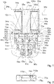
- Solenoid valves 10a, 10a', 10a" can be coupled together to form a valve chain 106a.
- the pressure connections 36a of the solenoid valves 10a in 3 Valve chain 106a shown as an example are connected to a common pressure line 108a.
- FIG. 4 shows a flowchart of a method with the solenoid valve device for the pressure-balanced solenoid valve 10a.
- a magnet part 12a and a valve part 22a are selected for coupling to form a magnet valve 10a.
- the selected magnet part 12a is connected to the selected one by means of the sealing and assembly device 28a Valve part 22a connected.
- the connection created in method step 116a between the magnet part 12a and the valve part 22a can be released.
- the connection created in method step 116a between the magnet part 12a and the valve part 22a is pressure-tight.
- connection created in method step 116a between the magnet part 12a and the valve part 22a connects the magnet part 12a and the valve part 22a to one another in a captive manner.
- the corresponding coupling elements 92a, 94a are brought into positive engagement with one another.
- the tappet unit 20a of the coupled valve part 22a is moved by a magnetic field generated by the magnet coil winding 14a of the magnet part 12a to switch the magnet valve 10a.
- the tappet unit 20a is pulled by the magnetic field in the direction of the magnet part 12a.
- the tappet unit 20a is deflected back by the restoring element 32a.
- the plunger unit 20a is pushed away from the magnetic part 12a by the restoring element 32a.
- the magnetic part 12a is decoupled from the valve part 22a in a non-destructive manner.
- the magnetic part 12a is replaced by a further magnetic part 12a, 12a', 12a" that is different from the magnetic part 12a and/or the valve part 22a is replaced by a further valve part 22a, 22a', 22a", that is different from the valve part 22a. 22a′′′ exchanged.
- the replaced additional magnet part 12a, 12a', 12a" is coupled to the remaining valve part 22a and/or the replaced additional valve part 22a, 22a', 22a", 22a′′′ is coupled to the remaining magnet part 12a.
- figure 5 10 shows an alternative solenoid valve 10b with an alternative solenoid valve device.
- the magnetic valve device has a magnetic part 12b and a valve part 22b.
- the magnet part 12b is hermetically overmoulded.
- the magnet part 12b has a magnet part housing 98b.
- the hermetic encapsulation of the magnet part 12b forms the magnet part housing 98b.
- the magnet part housing 98b is intended to shield the magnet part 12b from external influences, for example dirt or moisture.
- the valve part 22b has a housing 34b.
- the housing 34b of the valve part 22b and the magnet part housing 98b are connected to form the magnet valve 10b.
- the valve part 22b has a tappet unit 20b.
- the plunger unit 20b is intended to be moved by means of a magnetic field of the magnetic part 12b to actuate the magnetic valve 10b.
- the valve part 22b has a restoring element 32b.
- the restoring element 32b is provided to return the tappet unit 20b to an initial state when the magnetic field of the magnetic part 12b is switched off.
- the restoring element 32b is supported on the magnet part housing 98b.
- the magnet part housing 98b has a small thickness of a few millimeters.
- the magnet part housing 98b only slightly influences a transmission of the magnetic field from the magnet part 12b to the tappet unit 20b, in particular a magnetic field strength at the location of the tappet unit 20b is less than 5%, preferably less than 3% and preferably less than 1% lower than a magnetic field strength of an identical magnet part 12b, which has no magnet part housing 98b.
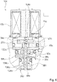
- the solenoid valve device has a Magnetic part 12c and a valve part 22c.
- the valve part 22c has a tappet unit 20c.
- the tappet unit 20c is intended to be moved by means of a magnetic field of the magnetic part 12c to actuate the magnetic valve 10c.
- the ram unit 20c has an armature ram 90c.
- the armature tappet 90c forms a flat armature 70c.
- the solenoid valve assembly includes a first valve seal 64c.
- the tappet assembly 20c includes the first valve seal 64c.
- the first valve seal 64c is pressed onto the armature tappet 90c.
- the solenoid valve assembly includes a second valve seal 128c.
- the tappet unit 20c has the second valve seal 128c.
- the second valve seal 128c is pressed onto the armature tappet 90c.
- the first valve seal 64c is spaced from the second valve seal 128c along an axis of movement 130c of the plunger assembly 20c.
- the first valve seal 64a is arranged behind the second valve seal 128c, viewed in the direction of the magnetic part 12c.
- the first valve seal 64c is arranged between the second valve seal 128c and the magnetic part 12c.
- the first valve seal 64c is spatially separate from the second valve seal 128c. Apart from the armature tappet 90c, the first valve seal 64c and the second valve seal 128c are free of a common carrier element.
- the first valve seal 64c moves with the second valve seal 128c and vice versa.
- the first valve seal 64c and the second valve seal 128c are provided to block and/or unblock different flow paths through the solenoid valve device.
- the valve part 22c has a first valve seat 50c.
- the valve part 22a has a housing 34c.
- the housing 34c has a pressure port 36c.
- the pressure connection 36c is arranged in the vicinity of the second valve seal 128c and/or a second valve seat 52c.
- the housing 34c has a working connection 38c.
- the working connection 38c is arranged in an intermediate region 134c between the first valve seal 64c and the second valve seal 128c.
- the housing 34c has a vent port 40c.
- the vent port 40c is in one Arranged in the vicinity of the first valve seal 64c, the first valve seat 50c and/or a third valve seat 132c.
- the first valve seal 64c is intended to sit sealingly on the first valve seat 50c in at least one operating state.
- the second valve seal 128c does not unseat in any operating condition of the solenoid valve assembly 6 on the first valve seat 50c.
- a sealing seat of the first valve seal 64c on the first valve seat 50c is in the embodiment of 6 the vent port 40c is closed.
- the valve part 22c has the second valve seat 52c.
- the second valve seal 128c is intended to sit sealingly on the second valve seat 52c in at least one operating state.
- the first valve seal 64c does not unseat in any operating condition of the solenoid valve assembly 6 sealingly on the second valve seat 52c.
- the valve part 22c has the third valve seat 132c.
- the first valve seal 64c is provided to sit sealingly on the third valve seat 132c in at least one operating state.
- the second valve seal 128c does not unseat in any operating condition of the solenoid valve assembly 6 on the third valve seat 132c.
- a connection of at least the ventilation connection 40c and/or at least the working connection 38c to a hollow space 104c on the magnet part side, in which in particular the flat armature 70c is arranged is closed.
- Cavity 104c is advantageously connected to pressure connection 36c and/or to pressure connection 36c via a pressure compensation element 30c of tappet unit 20c open.
- the design of 6 is free of a sliding seal, in particular a seal sliding along the tappet unit 20c.
- the solenoid valve device from 6 has at least essentially identical, in particular at least essentially identically arranged valve connections, ie the pressure connection 36c, the working connection 38c and the ventilation connection 40c. As a result, an exchangeability of different valve parts 22c can advantageously be made possible or maintained.
Landscapes
- Engineering & Computer Science (AREA)
- General Engineering & Computer Science (AREA)
- Mechanical Engineering (AREA)
- Physics & Mathematics (AREA)
- Electromagnetism (AREA)
- Fluid Mechanics (AREA)
- Transportation (AREA)
- Magnetically Actuated Valves (AREA)
Description
- Die Erfindung betrifft eine Magnetventilvorrichtung für ein druckausgeglichenes Magnetventil nach dem Oberbegriff des Anspruchs 1, ein druckausgeglichenes Magnetventil nach dem Oberbegriff des Anspruchs 17, ein Magnetventilsystem nach Anspruch 18 und ein Verfahren mit der Magnetventilvorrichtung nach Anspruch 21.
- Es ist bereits eine Magnetventilvorrichtung für ein druckausgeglichenes Magnetventil mit einem Magnetteil, aufweisend zumindest eine Magnetspulenwicklung, und mit einem Ventilteil, aufweisend zumindest eine Stößeleinheit, welche zumindest dazu vorgesehen ist, zumindest einen Durchflusspfad durch das Magnetventil zu steuern und welche zumindest dazu vorgesehen ist, mit einem innerhalb des Magnetteils erzeugten Magnetfeld zumindest zu einer Erzeugung zumindest einer Bewegung der Stößeleinheit wechselzuwirken, vorgeschlagen worden. Ein gattungsgemäßes Ventil ist im Dokument
WO 2006/079382 A1 offenbart. - Die Aufgabe der Erfindung besteht insbesondere darin, eine gattungsgemäße Vorrichtung mit einer besonders effizienten Magnetkraftnutzung bereitzustellen. Die Aufgabe wird erfindungsgemäß durch die Merkmale der Patentansprüche 1, 17, 18 und 21 gelöst, während vorteilhafte Ausgestaltungen und Weiterbildungen der Erfindung den Unteransprüchen entnommen werden können.
- Die Erfindung geht aus von einer Magnetventilvorrichtung für ein druckausgeglichenes Magnetventil, von einer insbesondere druckausgleichenden Magnetventilvorrichtung mit einem Magnetteil, aufweisend zumindest eine Magnetspulenwicklung und vorzugsweise zumindest einen zumindest teilweise in einem Inneren der Magnetspulenwicklung angeordneten Magnetkern, und mit einem Ventilteil, aufweisend zumindest eine Stößeleinheit, welche zumindest dazu vorgesehen ist, zumindest einen Durchflusspfad durch das Magnetventil zu steuern und welche zumindest dazu vorgesehen ist, mit einem innerhalb des Magnetteils erzeugten Magnetfeld zumindest zu einer Erzeugung zumindest einer Bewegung der Stößeleinheit wechselzuwirken.
- Es wird vorgeschlagen, dass der Magnetteil und der Ventilteil separierbare, unabhängig voneinander funktionsfähige Module ausbilden, welche insbesondere frei sind von gemeinsamen funktionellen Bauteilen, wie beispielsweise einem gemeinsamen Magnetanker. Dadurch kann vorteilhaft eine besonders effiziente Magnetkraftnutzung erreicht werden, insbesondere indem eine Reibkraft zwischen Komponenten des Magnetteils und Komponenten des Ventilteils bei einer Schaltung des Magnetventils reduziert werden kann. Vorteilhaft sind der Ventilteil, insbesondere die Stößeleinheit des Ventilteils, und der Magnetteil auch in einem montierten Zustand weitestgehend voneinander entkoppelt, d.h. insbesondere voneinander entkoppelt abgesehen von einer einfachen Abstützung des Ventilteils an dem Magnetteil und/oder abgesehen von einem einfachen, vorzugsweise planen, Sitz des Magnetteils auf dem Ventilteil. Vorteilhaft kann eine einfache Montage ermöglicht werden, insbesondere indem zu einer Herstellung einer vollen Funktionsfähigkeit des Magnetventils ausschließlich eine simple Verbindung zweier Module notwendig ist und eine aufwändige Ausrichtung der Einzelteile des Magnetventils, beispielsweise der Magnetspulenwicklung und der Stößeleinheit, zueinander vorteilhaft entfallen kann. Dadurch kann vorteilhaft eine Montage der Magnetventilvorrichtung, ein Umbau der Magnetventilvorrichtung und/oder ein Austausch eines Magnetteils oder eines Ventilteils der Magnetventilvorrichtung außerhalb der Produktionsstätte, z.B. bei direkt einem Kunden oder in einer Werkstatt, ermöglicht werden. Vorteilhaft kann eine einfache Konfektionierbarkeit eines Magnetventils ermöglicht werden, beispielsweise indem verschiedene Ventilteile oder verschiedene Magnetteile einfach miteinander kombinierbar sind. Durch diese Kombinierbarkeit kann vorteilhaft ein Logistikaufwand, beispielsweise ein Aufwand für eine Lagerhaltung einer Vielzahl verschiedener Ventile oder ein Aufwand für eine Dokumentation einer Vielzahl verschiedener Ventile gering gehalten werden, insbesondere indem nicht jede mögliche Kombination, d.h. insbesondere nicht jedes mögliche Magnetventil, dokumentiert und/oder vorrätig gehalten werden muss, sondern nur die einzelnen Magnetteile und Ventilteile, welche eine große Anzahl an Kombinationen erlauben. Vorteilhaft können dadurch Kosten gering gehalten werden. Druckausgleichende Magnetventile sind besonders vorteilhaft, da ein in dem Magnetventil herrschender Druck für eine Aufstellung einer Kräftebilanz des Magnetventils unberücksichtigt bleiben kann, demnach insbesondere nicht bei einer Auslegung von Magnetkräften berücksichtigt werden muss. Dadurch können Magnetkräfte, welche für eine Schaltung des Magnetventils notwendig sind, vorteilhaft niedrig gehalten werden, wodurch eine Größe der verwendeten Magnete vorteilhaft reduziert werden kann. Dadurch können vorteilhaft besonders kompakte und/oder besonders kostengünstige Magnetventile erhalten werden.
- Unter einem "druckausgeglichenen Magnetventil" soll insbesondere ein Magnetventil verstanden werden, welches zumindest im Wesentlichen frei ist von eine Ventilbewegung beeinflussenden und/oder erschwerenden Druckunterschieden auf verschiedenen, insbesondere gegenüberliegenden, Seiten des Magnetventils, insbesondere eines Ankers des Magnetventils. Unter einem "Magnetteil" soll insbesondere ein Modul der Magnetventilvorrichtung verstanden werden, welches dazu vorgesehen ist, ein Magnetfeld zu erzeugen, welches insbesondere zu einer Schaltung und/oder zu einer Steuerung eines Magnetventils vorgesehen ist. Unter einem "Ventilteil" soll insbesondere ein Modul der Magnetventilvorrichtung verstanden werden, welches dazu vorgesehen ist, einen Fluss und/oder einen Pfad eines Flusses, insbesondere einen Durchflusspfad, zu manipulieren, vorzugsweise zu steuern und/oder zu regeln, wozu der Ventilteil vorzugsweise eine bewegliche Ventildichtung aufweist, welche dazu vorgesehen ist, zumindest einen Pfad des Flusses zu blockieren und/oder freizugeben. Vorzugsweise sind der Ventilteil und der Magnetteil, insbesondere mittels zueinander korrespondierender Koppelelemente, auf einfache Weise miteinander koppelbar. Bevorzugt ist die Kopplung zwischen Ventilteil und Magnetteil zerstörungsfrei lösbar. Beispielsweise sind der Ventilteil und der Magnetteil mittels einer Formschlussverbindung, beispielsweise einer Clipsverbindung, einer Aufschraubverbindung, z.B. mittels eines Außengewindes des Magnetteils, einer Druckknopfverbindung, einer Klettverbindung und/oder dergleichen miteinander koppelbar. Alternativ oder zusätzlich können der Ventilteil und der Magnetteil mittels einer Schraubenverbindung, mittels einer Nietverbindung oder dergleichen miteinander koppelbar ausgebildet sein. Es ist zudem denkbar, dass die Kopplung zwischen dem Ventilteil und dem Magnetteil zumindest im Wesentlichen druckdicht ausgebildet ist. Unter einer "im Wesentlichen druckdichten" Kopplung soll insbesondere eine Kopplung verstanden werden, welche zumindest dazu vorgesehen ist, einem Druck von wenigstens 10 bar, vorzugsweise wenigstens 20 bar, vorteilhaft wenigstens 30 bar, bevorzugt wenigstens 50 bar und besonders bevorzugt wenigstens 80 bar standzuhalten.
- Unter einer Stößeleinheit soll insbesondere eine Einheit verstanden werden, welche dazu vorgesehen ist, eine Öffnungs-, Schließungs- und/oder Umschaltbewegung des Magnetventils zu übertragen und/oder zu erzeugen. Die Stößeleinheit umfasst zumindest einen Ankerstößel, welcher einstückig oder mehrteilig ausgebildet sein kann. Beispielsweise kann ein magnetteilseitiger Teil des Ankerstößels zumindest teilweise aus einem ferromagnetischen und/oder weichmagnetischen Material, beispielsweise einem Eisen oder einer Eisenlegierung, und ein dem Magnetteil abgewandter Teil des Ankerstößels zumindest teilweise aus einem abdichtenden Material, beispielsweise einem Elastomer, ausgebildet sein. Vorzugsweise ist zumindest der magnetteilseitige Teil des Ankerstößels dazu vorgesehen, mit dem Magnetfeld des Magnetteils wechselzuwirken. Insbesondere ist das Magnetfeld des Magnetteils dazu vorgesehen, den Ankerstößel in Richtung des Magnetteils zu ziehen. Insbesondere ist die Stößeleinheit innerhalb des Ventilteils beweglich gelagert. Insbesondere ist zumindest der Ankerstößel gleitend innerhalb des Ventilteils gelagert. Unter einem "Modul" soll insbesondere ein austauschbares, insbesondere komplexes, Element innerhalb eines Gesamtsystems, eines Gerätes oder einer Maschine, vorzugsweise innerhalb eines Magnetventils, verstanden werden, welches vorzugsweise eine geschlossene Funktionseinheit bildet. Insbesondere sind die Module, vorzugsweise zumindest das durch den Ventilteil gebildete Modul und das durch den Magnetteil gebildete Modul, zu einem Gesamtsystem, vorzugsweise zu dem Magnetventil, zusammenfügbar. Vorzugsweise weisen die Module, vorzugsweise zumindest das durch den Ventilteil gebildete Modul und das durch den Magnetteil gebildete Modul, jeweils zumindest eine Schnittstelle auf, welche insbesondere dazu vorgesehen sind, eine Interaktion der Module untereinander, beispielsweise über das Magnetfeld des Magnetteils, zu erlauben. Die Magnetspulenwicklung bildet insbesondere ein Solenoid aus. Unter einem "Solenoid" soll insbesondere eine zylindrische Metallspule verstanden werden, welche bei einem Stromdurchfluss ähnlich wie ein Stabmagnet wirkt. Unter "einstückig" soll insbesondere zumindest stoffschlüssig verbunden verstanden werden, beispielsweise durch einen Schweißprozess, einen Klebeprozess, einen Anspritzprozess und/oder einen anderen, dem Fachmann als sinnvoll erscheinenden Prozess, und/oder vorteilhaft in einem Stück geformt verstanden werden, wie beispielsweise durch eine Herstellung aus einem Guss und/oder durch eine Herstellung in einem Ein- oder Mehrkomponentenspritzverfahren und vorteilhaft aus einem einzelnen Rohling. Der Magnetkern ist insbesondere als ein, vorzugsweise zumindest abschnittsweise unterbrochener, Eisenkreis ausgebildet. Alternativ kann der Magnetteil auch frei von einem Magnetkern, insbesondere einem Eisenkreis ausgebildet sein.
- Ferner wird vorgeschlagen, dass der Ventilteil zumindest im Wesentlichen frei ist von, insbesondere beweglich gelagerten, in zumindest einem Betriebszustand in den Magnetteil zumindest teilweise eingreifenden Komponenten, insbesondere abgesehen von ausschließlich für eine gegenseitige Fixierung der Module des Ventilteils und des Magnetteils vorgesehenen Komponenten wie beispielsweise Kraft- oder Formschlusseingriffe. Dadurch kann vorteilhaft eine besonders effiziente Magnetkraftnutzung erreicht werden, insbesondere indem eine Reibkraft zwischen Komponenten des Magnetteils und Komponenten des Ventilteils bei einer Schaltung des Magnetventils reduziert werden kann. Insbesondere kann dadurch vorteilhaft eine Reibung zumindest eines Teils der beweglich gelagerten Stößeleinheit mit einem Teil der Magneteinheit, beispielsweise einer Dichtung oder einer Wandung, welche die Stößeleinheit innerhalb des Magnetteils führt, vermieden werden. Dadurch kann vorteilhaft ein Verschleiß reduziert werden, eine Überhitzung von Komponenten des Magnetventils, beispielsweise eine übermäßige Erwärmung des Ventilteils durch einen zu großen Wärmeübertrag von der betriebsheißen Magnetspulenwicklung des Magnetteils auf den Ventilteil, verhindert werden und/oder eine für eine Bewegung der Stößeleinheit notwendige Magnetkraft gering gehalten werden. Vorteilhaft kann eine Komplexität, insbesondere ein Herstellungsaufwand des Magnetventils, gering gehalten werden, indem vorteilhaft auf eine Einpassung und/oder Anpassung einer in zumindest dem Betriebszustand in den Magnetteil zumindest teilweise eingreifenden Komponente der Ventileinheit, beispielsweise eines Magnetankers, in eine Öffnung des Magnetteils, insbesondere in das Innere einer Spulenwicklung des Magnetteils, verzichtet werden kann. Dadurch kann vorteilhaft auf ein aufwändiges Einstellen von Fluchtungstoleranzen zwischen dem Magnetteil und dem Ventilteil verzichtet werden, wodurch besonders vorteilhaft zusätzliche durch eine ungenaue Fluchtung und/oder durch Fluchtungsfehler erzeugte Reibungskräfte vermieden werden können. Dadurch, dass weniger zusätzliche Reibkräfte einer Bewegung der Stößeleinheit entgegenwirken, sind die für die Bewegung der Stößeleinheit notwendigen Magnetkräfte vorteilhaft reduzierbar, wodurch insbesondere Kosten für die Spulenwicklung und/oder ein nötiger Bauraum für die Spulenwicklung reduziert werden können. Zudem kann vorteilhaft eine Montage der Magnetventilvorrichtung, ein Umbau der Magnetventilvorrichtung und/oder ein Austausch eines Magnetteils und/oder eines Ventilteils vereinfacht werden, insbesondere indem keine genaue Einstellung von Fluchtungstoleranzen nötig ist. Vorteilhaft kann die Montage der Magnetventilvorrichtung, der Umbau der Magnetventilvorrichtung und/oder der Austausch des Magnetteils und/oder des Ventilteils unabhängig von einem Einsatz von Spezialwerkzeugen zu einer exakten Ausrichtung vorgenommen werden. Darunter, dass eine Baueinheit einer Vorrichtung "im Wesentlichen frei" ist von in eine andere Baueinheit der Vorrichtung eingreifenden Komponenten, soll insbesondere verstanden werden, dass die Baueinheit frei ist von für eine Hauptfunktion zuständigen, insbesondere für eine Ventilschaltfunktion zuständigen, Komponenten, welche in die andere Baueinheit eingreifen. Unter "teilweise eingreifend" soll insbesondere zumindest zu 15 % eines Gesamtvolumens, vorzugsweise zumindest zu 10 % eines Gesamtvolumens, bevorzugt zumindest zu 5 % eines Gesamtvolumens und besonders bevorzugt zumindest zu 2 % eines Gesamtvolumens verstanden werden.
- Zudem wird vorgeschlagen, dass der Magnetteil zumindest im Wesentlichen frei ist von beweglich gelagerten Komponenten und/oder von in zumindest einem Betriebszustand in den Ventilteil zumindest teilweise eingreifenden Komponenten. Dadurch kann vorteilhaft eine besonders effiziente Magnetkraftnutzung erreicht werden, insbesondere indem eine Reibkraft zwischen Komponenten des Magnetteils und Komponenten des Ventilteils und/oder zwischen Komponenten innerhalb des Magnetteils bei einer Schaltung des Magnetventils reduziert werden kann. Dadurch kann vorteilhaft ein Verschleiß reduziert werden, eine Überhitzung von Komponenten des Magnetventils verhindert werden, beispielsweise eine übermäßige Erwärmung des Ventilteils durch einen zu großen Wärmeübertrag von der betriebsheißen Magnetspulenwicklung des Magnetteils auf den Ventilteil, und/oder eine für eine Bewegung der Stößeleinheit notwendige Magnetkraft gering gehalten werden. Zudem kann vorteilhaft eine Komplexität, insbesondere ein Herstellungsaufwand, insbesondere für den Magnetteil gering gehalten werden.
- Des Weiteren wird vorgeschlagen, dass der Ventilteil und/oder der Magnetteil eine Dichtungs- und Montagevorrichtung aufweist, welche dazu vorgesehen ist, eine, insbesondere druckdichte, Kopplung des durch den Ventilteil gebildeten Moduls und des durch den Magnetteil gebildeten Moduls herzustellen. Dadurch kann insbesondere eine vorteilhafte und/oder einfache Montage der Magnetventilvorrichtung erreicht werden. Die Dichtungs- und Montagevorrichtung umfasst insbesondere zumindest ein Koppelelement, vorzugsweise die korrespondierenden Koppelelemente. Die Dichtungs- und Montagevorrichtung umfasst insbesondere zumindest ein Dichtelement, beispielsweise eine Kunststoffdichtung wie z.B. einen (Elastomer-)O-Ring und/oder eine Metalldichtung wie z.B. einen Kupfer-Dichtring. Die Dichtungs- und Montagevorrichtung ist insbesondere dazu vorgesehen, ein Inneres des Magnetventils, insbesondere den Durchflusspfad des Magnetventils gegenüber einem das Magnetventil umgebenden Äußeren, abzudichten. Alternativ oder zusätzlich kann die Dichtungs- und Montagevorrichtung dazu vorgesehen sein, den Magnetteil gegenüber dem Ventilteil, insbesondere gegenüber in dem Ventilteil angeordneten Hohlräumen zu einer Fluidführung oder -aufnahme, abzudichten oder umgekehrt. Unter "vorgesehen" soll insbesondere speziell programmiert, ausgelegt und/oder ausgestattet verstanden werden. Darunter, dass ein Objekt zu einer bestimmten Funktion vorgesehen ist, soll insbesondere verstanden werden, dass das Objekt diese bestimmte Funktion in zumindest einem Anwendungs- und/oder Betriebszustand erfüllt und/oder ausführt.
- Wenn das mit dem Ventilteil gekoppelte, durch das Magnetteil gebildete Modul zerstörungsfrei von dem Ventilteil entkoppelbar ist, kann vorteilhaft ein einfacher Austausch, ein einfacher Umbau und/oder eine einfache Reparatur der Magnetventilvorrichtung ermöglicht werden, wodurch vorteilhaft Kosten gering gehalten werden können. Zudem kann dadurch vorteilhaft eine hohe Flexibilität erreicht werden, beispielsweise indem eine Magnetventilvorrichtung durch einen Umbau einfach an geänderte Betriebsbedingungen angepasst werden kann, z.B. kann ein Magnetteil mit einem stärkeren Magneten oder mit einem anderen Stromanschluss oder ein Ventilteil mit einer anderen Ventilschaltung oder einer anderen Durchflusskapazität montiert werden. Vorteilhaft ist die Magnetventilvorrichtung in einem in ein Gerät, beispielsweise in einem Fahrzeug, eingebauten Zustand zerstörungsfrei entkoppelbar. Darunter, dass das "durch das Magnetteil gebildete Modul zerstörungsfrei von dem Ventilteil entkoppelbar ist", soll insbesondere verstanden werden, dass zumindest das Magnetteil oder das Ventilteil, vorzugsweise das Magnetteil und das Ventilteil, einen Entkoppelvorgang zerstörungsfrei überstehen, wobei insbesondere eine volle Funktionsfähigkeit der Module des Ventilteils und/oder des Magnetteils auch nach dem Entkoppelvorgang erhalten bleibt.
- Außerdem wird vorgeschlagen, dass die Stößeleinheit, insbesondere zumindest auf einer in einem montierten Zustand dem Magnetteil zugewandten Seite der Stößeleinheit, vorzugsweise des Ankerstößels der Stößeleinheit, zumindest teilweise einen Flachanker ausbildet. Dadurch können vorteilhafte Wechselwirkungseigenschaften zwischen dem Magnetfeld des Magnetteils und dem Ventilteil, insbesondere der Stößeleinheit, erreicht werden. Vorteilhaft kann eine besonders effektive Kraftübertragung einer Magnetkraft erreicht werden. Vorteilhaft kann eine Kopplung des Magnetfelds des Magnetteils mit einem ferromagnetischen Anteil des Ankerstößels der Stößeleinheit in einem betriebsbereiten Zustand der Magnetventilvorrichtung optimiert werden. Vorteilhaft kann durch den Flachanker eine hohe Magnetkraft erreicht werden. Insbesondere bei einem Einsatz der Magnetventilvorrichtung in einem Fahrzeug, welches Umgebungstemperaturen zwischen -40°C und +80 °C, insbesondere bis zu 130°C, ausgesetzt sein kann, kommt es bei einer Verwendung von gleitenden Dichtungen potentiell zu einer signifikanten temperaturabhängigen Reibhysterese, welche vorteilhaft mittels der durch die Verwendung eines Flachankers erheblich erhöhten Magnetkraft überwunden werden kann. Unter einem "Flachanker" soll insbesondere ein Ankerstößel verstanden werden, welcher an zumindest einem, insbesondere in eine vorgesehene Bewegungsrichtung des Ankerstößels zeigenden, Ende eine Abflachung, insbesondere eine Art Scheibe, ausbildet. Insbesondere weist die Abflachung des Ankerstößels, insbesondere die Scheibe, senkrecht zu einer Bewegungsachse des Ankerstößels einen Durchmesser auf, welcher wesentlich größer ist als ein Durchmesser des Magnetkerns, welcher zu einer Wechselwirkung mit dem Ankerstößel vorgesehen ist und/oder wesentlich größer ist als ein Durchmesser des Inneren der Magnetspulenwicklung. Insbesondere weist die Abflachung des Ankerstößels, insbesondere die Scheibe, senkrecht zu einer Bewegungsachse des Ankerstößels einen Durchmesser auf, welcher wesentlich größer ist als ein mittlerer Durchmesser der Stößeleinheit senkrecht zu einer Bewegungsachse des Ankerstößels. Unter "wesentlich größer" soll zumindest um 10 % größer, vorzugsweise zumindest um 20 %, bevorzugt zumindest um 30 % größer und besonders bevorzugt zumindest um 100 % größer verstanden werden.
- Zusätzlich wird vorgeschlagen, dass die Stößeleinheit zumindest ein Druckausgleichselement aufweist, welches insbesondere dazu vorgesehen ist, einen Druck auf einer dem Magnetteil zugewandten Seite der Stößeleinheit und einen Druck auf einer dem Magnetteil abgewandten Seite der Stößeleinheit auszugleichen. Dadurch kann vorteilhaft eine ausgeglichene Druckbilanz innerhalb der Magnetventilvorrichtung bei einem Betrieb der Stößeleinheit erreicht werden. Insbesondere kann ein Druckunterschied auf verschiedenen Seiten der Stößeleinheit bei einer Bestimmung der Kräftebilanz des Magnetventils vorteilhaft vernachlässigt werden. Dadurch ist vorteilhaft eine geringe Magnetkraft für einen ordnungsgemäßen Betrieb der Stößeleinheit erforderlich. Dadurch kann vorteilhaft eine Magnetspulenwicklung besonders klein ausgelegt werden, wodurch Kosten und Bauraum vorteilhaft reduziert werden können. Das Druckausgleichselement ist insbesondere als eine durchgehende Ausnehmung, insbesondere als eine durchgehende Bohrung, durch die Stößeleinheit, insbesondere den Ankerstößel, ausgebildet, welche sich vorzugsweise zumindest im Wesentlichen parallel zu einer Längsrichtung der Stößeleinheit und/oder zu einer vorgesehenen Bewegungsrichtung der Stößeleinheit erstreckt. Unter "im Wesentlichen parallel" soll hier insbesondere eine Ausrichtung einer Richtung relativ zu einer Bezugsrichtung, insbesondere in einer Ebene, verstanden werden, wobei die Richtung gegenüber der Bezugsrichtung eine Abweichung insbesondere kleiner als 8°, vorteilhaft kleiner als 5° und besonders vorteilhaft kleiner als 2° aufweist. Insbesondere ist denkbar, dass die Stößeleinheit mehr als ein Druckausgleichselement aufweist. Insbesondere ist das Druckausgleichselement dazu vorgesehen, einen Druckanschluss des Ventilteils mit zumindest einem weiteren Hohlraum des Ventilteils zu verbinden, welcher abgesehen von dem Druckausgleichselement abgedichtet ist zu dem Druckanschluss und/oder zu allen weiteren Anschlüssen des Ventilteils. Der Druckanschluss ist insbesondere zu einem Anschluss der Magnetventilvorrichtung an eine Druckleitung vorgesehen. Es ist denkbar, dass eine Mehrzahl an, beispielsweise miteinander verketteten Magnetventilvorrichtungen an eine identische Druckleitung angeschlossen sind.
- Außerdem wird vorgeschlagen, dass die Stößeleinheit zumindest ein Rückstellelement aufweist, welches gegen den Magnetteil, insbesondere den Magnetkern des Magnetteils und/oder gegen ein den Magnetteil umgebendes Magnetteilgehäuse, abgestützt ist. Dadurch kann vorteilhaft eine effektive Ventilschaltung des Magnetventils ermöglicht werden. Zudem kann vorteilhaft ein stromloser Schaltzustand des Magnetventils erzeugt werden. Weiterhin kann durch eine direkte Abstützung gegen den Magnetteil eine kompakte Bauweise der Magnetventilvorrichtung erreicht werden. Das Rückstellelement ist insbesondere dazu vorgesehen, die Stößeleinheit nach einem Abschalten des Magnetfelds der Magneteinheit in einen Ruhezustand und/oder einen Ausgangszustand zurück auszulenken. Das Rückstellelement ist insbesondere dazu vorgesehen, eine Rückstellkraft zu erzeugen, welche, entgegen einer anziehend auf die Stößeleinheit wirkende, durch die Magnetspulenwicklung erzeugte Kraft wirkt. Zudem ist das Rückstellelement dazu vorgesehen, ein magnetisches Haften der Stößeleinheit an dem Magnetteil, beispielsweise durch eine zumindest teilweise Magnetisierung der Stößeleinheit, zu unterbinden. Es ist denkbar, dass die Magnetventilvorrichtung eine Mehrzahl an Rückstellelementen aufweist. Das Rückstellelement ist insbesondere als eine Feder, vorzugsweise eine Spiralfeder und bevorzugt eine Druckfeder, ausgebildet. Insbesondere kontaktiert das Rückstellelement den Magnetteil direkt. Alternativ ist vorstellbar, dass das Rückstellelement indirekt, also beispielsweise mittels eines zwischengeschalteten Kraftübertragungselements, gegen den Magnetteil abgestützt ist.
- Weiterhin wird vorgeschlagen, dass das Rückstellelement zumindest teilweise innerhalb des Druckausgleichselements angeordnet ist. Dadurch kann vorteilhaft eine besonders kompakte Bauweise erreicht werden. Zudem kann vorteilhaft eine effektive und gleichmäßig verteilte Kraftübertragung zwischen dem Rückstellelement und der Stößeleinheit erfolgen. Insbesondere ist das Druckausgleichselement gegen zumindest eine Schulter und/oder gegen zumindest eine Auskragung innerhalb des Druckausgleichselements abgestützt. Insbesondere weist das Druckausgleichselement einen Abschnitt mit einem vergrößerten Querschnitt auf, innerhalb welchem das Rückstellelement eingebracht ist. Alternativ könnte das Druckausgleichselement einen gleichbleibenden oder auf der magnetteiligen Seite der Stößeleinheit kleiner werdenden Querschnitt aufweisen, wobei beispielsweise nach innen gerichtete Auskragungen entlang eines Umfangs angeordnet sind, mittels welchen das Rückstellelement gegen die Stößeleinheit abgestützt ist.
- Ferner wird vorgeschlagen, dass der Magnetteil und der Ventilteil zumindest im Wesentlichen thermisch voneinander entkoppelt sind. Dadurch kann vorteilhaft eine Ausbildung einer Reibkrafthysterese, insbesondere einer temperaturabhängigen Reibkrafthysterese, reduziert oder bevorzugt vermieden werden. Insbesondere kann vorteilhaft verhindert werden, dass eine Magneterwärmung durch einen Betrieb der Magnetspulenwicklung direkt, insbesondere durch eine Kontaktwärmeleitung, auf eine Dichtung, insbesondere auf eine gleitende Dichtung, der Magnetventilvorrichtung übertragen wird. Dadurch kann vorteilhaft ein Reibwiderstand gering gehalten werden, wodurch eine maximal nötige Magnetkraft gering gehalten werden kann und wodurch vorteilhaft eine reduzierte Baugröße und reduzierte Kosten ermöglicht werden können. Darunter, dass zwei Bauteile "wesentlich thermisch voneinander entkoppelt" sind soll insbesondere verstanden werden, dass für ein Wärmefluss zwischen den beiden Bauteilen zumindest im Wesentlichen, insbesondere zumindest zu 66 %, vorzugsweise zumindest zu 75 % und bevorzugt zumindest zu 90 % eine Wärmestrahlung und/oder ein Fluid verantwortlich ist.
- Zudem wird vorgeschlagen, dass der Ventilteil zumindest ein Gehäuse mit zumindest einem Druckanschluss, zumindest einem Arbeitsanschluss und/oder zumindest einem Entlüftungsanschluss umfasst, wobei der Druckanschluss zumindest mittels einer Dichtungsanordnung gegenüber dem Arbeitsanschluss und/oder dem Entlüftungsanschluss abgedichtet ist. Dadurch kann insbesondere eine vorteilhafte Ventilkonfiguration erreicht werden. Das Gehäuse ist insbesondere als ein Drehteil, insbesondere als ein Metalldrehteil, als ein Spritzgussteil, insbesondere ein Kunststoffspritzgussteil, oder als ein 3D-Druckteil ausgebildet. Insbesondere ist der Druckanschluss in zumindest einer Stellung der Stößeleinheit in dem Ventilteil gegen den Arbeitsanschluss abgedichtet. Insbesondere ist der Druckanschluss in zumindest einer Stellung der Stößeleinheit in dem Ventilteil gegen den Entlüftungsanschluss abgedichtet. Die Dichtungsanordnung ist insbesondere dazu vorgesehen, das Gehäuse und die Stößeleinheit druckdicht zu verbinden. Die Dichtungsanordnung ist insbesondere dazu vorgesehen, eine Abdichtung zwischen der Stößeleinheit und dem Gehäuse bei einer Bewegung der Stößeleinheit aufrechtzuerhalten. Die Dichtungsanordnung umfasst insbesondere eine gleitende Dichtung. Die gleitende Dichtung ist insbesondere als ein gefetteter O-Ring oder als ein speziell beschichtetes Elastomer ausgebildet. Alternativ ist die Dichtungsanordnung als eine hart-dichtende Dichtungsanordnung ausgebildet. Alternativ umfasst die Dichtungsanordnung zumindest einen insbesondere druckdichten Faltenbalg und/oder zumindest eine Membran-Dichtung.
- Außerdem wird vorgeschlagen, dass zumindest eine Dichtung, insbesondere die gleitende Dichtung, der Dichtungsanordnung einen Dichtungsdurchmesser aufweist, welcher einem Wirkdurchmesser zumindest eines Ventilsitzes des Ventilteils, vorzugsweise aller Ventilsitze des Ventilteils, zumindest im Wesentlichen entspricht. Dadurch kann vorteilhaft eine druckausgleichende Konfiguration des Ventilteils ermöglicht werden. Insbesondere kann dadurch vorteilhaft ein Druckgefälle zwischen einem an dem Ventilsitz anliegendem Druck und einem an der Dichtung der Dichtungsanordnung anliegendem Druck auf einen Wert nahe null reduziert werden. Unter einem "Dichtungsdurchmesser" soll insbesondere ein Durchmesser, vorzugsweise ein Innendurchmesser der gleitenden Dichtung, insbesondere des Dichtungsrings, welcher das Gehäuse gegen die Stößeleinheit abdichtet, verstanden werden. Unter einem "Wirkdurchmesser" soll insbesondere ein minimaler Durchmesser einer Öffnung eines Ventilsitzes verstanden werden. Insbesondere ist die Dichtung der Dichtungsanordnung und die Öffnung des Ventilsitzes zumindest im Wesentlichen rund. Vorzugsweise weisen alle Ventilsitze des Ventilteils zumindest im Wesentlichen identische Wirkdurchmesser auf. Darunter, dass sich zwei Parameter "im Wesentlichen entsprechen", soll insbesondere verstanden werden, dass die zwei Parameter eine Differenz aufweisen, welche weniger als 5 %, vorzugsweise weniger als 3 % und bevorzugt weniger als 1 % eines Absolutwerts eines der Parameter beträgt.
- Wenn die Dichtungsanordnung zumindest eine gleitende Dichtung umfasst, können vorteilhaft gute Dichteigenschaften bei gleichzeitig moderaten Kosten erreicht werden.
- Des Weiteren wird vorgeschlagen, dass die gleitende Dichtung einen Dichtring umfasst, welcher zumindest zu einem Großteil aus einem Elastomer ausgebildet ist, wobei der Elastomer eine dünne, insbesondere eine Schichtdicke von weniger als 0,5 mm, bevorzugt weniger als 0,25 mm aufweisende, Schicht aus Polytetrafluorethylen (Teflon) aufweist. Dadurch kann vorteilhaft eine Magnetventilvorrichtung für ein druckausgeglichenes Magnetventil geschaffen werden, welche eine besonders verschleißresistente und/oder besonders reibungsarme und dennoch hoch dichtende gleitende Dichtung umfasst. Dadurch kann vorteilhaft eine hohe Lebensdauer erreicht werden. Vorteilhaft kann eine Reibkraft der Dichtung um 80 %reduziert werden. Zudem kann vorteilhaft eine Reibhysterese verringert werden. Des Weiteren kann vorteilhaft eine im Wesentlichen temperaturunabhängige Reibhysterese erreicht werden. Das Elastomer ist vorzugsweise als ein Kautschuk, insbesondere ein hydrierter Acrylnitrilbutadien-Kautschuk oder als ein Fluorkautschuk, ausgebildet. Insbesondere ist der Dichtring als ein Nutring mit einer, vorzugsweise V-förmigen, in Richtung einer Symmetrieachse des Nutrings geöffneten, rings um den Nutring verlaufenden, Vertiefung ausgebildet.
- Zudem wird vorgeschlagen, dass zumindest der Magnetteil hermetisch umspritzt ist. Dadurch kann vorteilhaft eine Abschirmung des Magnetteils von einer Verschmutzung, insbesondere von einem potentiell korrosiven Druckfluid, welches in den Fluidleitungen des Ventilteils, insbesondere auch in dem Druckausgleichselement, geführt ist, ermöglicht werden. Dadurch kann vorteilhaft eine hohe Lebensdauer erreicht werden. Zudem kann vorteilhaft eine einfache Reinigung eines demontierten Magnetteils ermöglicht werden. Insbesondere bildet die hermetische Umspritzung ein vollständig abgeschlossenes, das Magnetteil umgebendes Magnetteilgehäuse aus. Insbesondere ist der Magnetteil mittels eines Kunststoffs hermetisch umspritzt. Unter der Wendung "hermetisch umspritzt" soll insbesondere vollständig und zumindest gegen Schmutzpartikel, vorzugsweise gegen Flüssigkeiten dichtend umspritzt verstanden werden. Insbesondere kann dadurch vorteilhaft eine Anwendung des Magnetteils unter feuchten Umgebungsbedingungen, beispielsweise in einem Außenbereich, z.B. Motorbereich, eines Fahrzeugs ermöglicht werden. Die hermetische Umspritzung weist eine Dicke von zumindest 1 mm, vorzugsweise zumindest 3 mm, bevorzugt zumindest 5 mm und besonders bevorzugt höchstens 20 mm auf.
- Weiterhin wird vorgeschlagen, dass die Stößeleinheit die zumindest eine erste Ventildichtung und zumindest eine zweite Ventildichtung aufweist, welche insbesondere entlang einer Bewegungsachse der Stößeleinheit, insbesondere eines Ankerstößels der Stößeleinheit, von der ersten Ventildichtung beabstandet ist und/oder vorzugsweise von der ersten Ventildichtung getrennt ausgebildet ist, wobei die Ventildichtungen dazu vorgesehen sind, jeweils unterschiedliche Durchflusspfade durch das Magnetventil zu blockieren und/oder freizugeben. Vorteilhaft kann dadurch eine einfache Montage ermöglicht werden, insbesondere indem auf eine zusätzliche Gleitdichtung verzichtet werden kann. Vorteilhaft kann eine hohe Lebensdauer erreicht werden und/oder ein Verschleiß reduziert werden. Insbesondere sind die Ventildichtungen an unterschiedlichen Positionen entlang der Bewegungsachse der Stößeleinheit, insbesondere des Ankerstößels der Stößeleinheit, angeordnet. Insbesondere entspricht ein Abstand der Ventildichtungen entlang der Bewegungsachse zumindest einem Abstand der zwei am weitesten voneinander entfernten Ventilsitze aller durch die Stößeleinheit verschließbaren und/oder öffenbaren Ventilsitze der Magnetventileinheit. Insbesondere ist keiner der Ventilanschlüsse der Magnetventileinheit, insbesondere nicht der Druckanschluss, nicht der Arbeitsanschluss und/oder nicht der Entlüftungsanschluss, gleichzeitig durch die erste Ventildichtung und die zweite Ventildichtung verschließbar.
- Außerdem wird ein druckausgeglichenes Magnetventil mit der Magnetventilvorrichtung vorgeschlagen, wobei das Magnetventil als 3/2 NO-("normally open")-Ventil, als 3/2 NC-("normally closed")-Ventil, als 2/2 NO-Ventil oder als 2/2 NC-Ventil ausgebildet ist. Dadurch kann insbesondere ein Ventil mit vorteilhaften Ventileigenschaften erreicht werden. Insbesondere kann der Ventilteil des Magnetventils beliebig gewechselt werden, um entweder ein 3/2 NO-Ventil, ein 3/2 NC-Ventil, ein 2/2 NO-Ventil oder ein 2/2 NC-Ventil zu erhalten, insbesondere wenn bei dem Wechsel des Ventilteils eine entsprechende Umordnung von Magnetventilanschlüssen des Magnetventils vorgenommen wird. Dadurch kann vorteilhaft eine hohe Flexibilität erreicht werden.
- Zudem wird ein Magnetventilsystem mit einer Magnetventilvorrichtung vorgeschlagen, wobei das Magnetventilsystem eine Mehrzahl an zumindest teilweise unterschiedlich zueinander ausgebildeten, austauschbar mit dem Ventilteil koppelbaren und als separierbares Modul ausgebildeten, Magnetteilen aufweist, wobei die Magnetteile insbesondere unterschiedliche Magnetspulenwicklungen und/oder unterschiedliche elektrische Anschlussvorrichtungen und/oder elektrische Steuervorrichtungen aufweisen und/oder wobei das Magnetventilsystem einer Mehrzahl an zumindest teilweise unterschiedlich zueinander ausgebildeten, austauschbar mit dem Magnetteil koppelbaren und als separierbares Modul ausgebildeten, Ventilteilen aufweist, wobei die Ventilteile insbesondere unterschiedliche Gehäuse mit unterschiedlichen Zu- und/oder Ableitungen aufweisen. Dadurch kann vorteilhaft eine besonders effiziente Magnetkraftnutzung erreicht werden, insbesondere indem eine exakte Abstimmung und/oder Auslegung eines Magnetventils für ein bestimmtes System mittels einer entsprechenden Auswahl von miteinander kombinierten Modulen erreicht werden kann. Vorteilhaft kann zudem eine hohe Flexibilität erreicht werden. Insbesondere weisen die Magnetteile unterschiedliche Anschlussvorrichtungen auf, welche beispielsweise unterschiedliche Steckersysteme bzw. Steckervarianten aufweisen und/oder für unterschiedliche Spannungsquellen ausgelegt sind. Insbesondere weisen die Ventilteile unterschiedliche Durchflusspfade auf, welche sich beispielsweise in ihrem Querschnitt, insbesondere in ihrer maximal möglichen Durchflussmenge, in der Anzahl der Anschlüsse, insbesondere Zu- und/oder Abläufe, und/oder in der Art der stromlosen Nullstellung (NO/NC) unterscheiden. Beispielsweise umfasst das Magnetventilsystem Ventilteile, welche für eine Ausbildung von 3/2-NO-Magnetventilen, 3/2-NC-Magnetventilen, 2/2-NO-Magnetventilen oder 2/2-NC-Magnetventilen vorgesehen sind, insbesondere jeweils mit mehreren möglichen Dimensionierungen der Durchflussmengen.
- Zudem werden das Magnetteil der Magnetventilvorrichtung und das Ventilteil der Magnetventilvorrichtung vorgeschlagen.
- Des Weiteren wird ein Verfahren mit einer Magnetventilvorrichtung für ein druckausgeglichenes Magnetventil, mit einem Magnetventil und/oder mit einem Magnetventilsystem vorgeschlagen. Dadurch kann vorteilhaft eine besonders effiziente Magnetkraftnutzung erreicht werden.
- Die erfindungsgemäße Magnetventilvorrichtung für ein druckausgeglichenes Magnetventil, das erfindungsgemäße druckausgeglichene Magnetventil, das erfindungsgemäße Magnetventilsystem und/oder das erfindungsgemäße Verfahren mit der Magnetventilvorrichtung soll/sollen hierbei nicht auf die oben beschriebene Anwendung und Ausführungsform beschränkt sein. Insbesondere kann die erfindungsgemäße Magnetventilvorrichtung für ein druckausgeglichenes Magnetventil, das erfindungsgemäße druckausgeglichene Magnetventil, das erfindungsgemäße Magnetventilsystem und/oder das erfindungsgemäße Verfahren mit der Magnetventilvorrichtung zu einer Erfüllung einer hierin beschriebenen Funktionsweise eine von einer hierin genannten Anzahl von einzelnen Elementen, Bauteilen und Einheiten abweichende Anzahl aufweisen.
- Weitere Vorteile ergeben sich aus der folgenden Zeichnungsbeschreibung. In den Zeichnungen sind drei Ausführungsbeispiele der Erfindung dargestellt. Die Zeichnungen, die Beschreibung und die Ansprüche enthalten zahlreiche Merkmale in Kombination. Der Fachmann wird die Merkmale zweckmäßigerweise auch einzeln betrachten und zu sinnvollen weiteren Kombinationen zusammenfassen.
- Es zeigen:
- Fig. 1
- eine schematische Schnittansicht eines Magnetventils mit einer Magnetventilvorrichtung,
- Fig. 2
- eine schematische Schnittansicht eines Dichtrings einer gleitenden Dichtung der Magnetventilvorrichtung,
- Fig. 3
- eine schematische Darstellung eines Magnetventilsystems zur Bildung verschiedener Magnetventile,
- Fig. 4
- ein Ablaufdiagramm eines Verfahrens mit dem Magnetventil,
- Fig. 5
- eine schematische Schnittansicht eines alternativen Magnetventils mit einer alternativen Magnetventilvorrichtung und
- Fig. 6
- eine schematische Schnittansicht eines weiteren alternativen Magnetventils mit einer weiteren alternativen Magnetventilvorrichtung.
-
Fig. 1 zeigt ein Magnetventil 10a. Das Magnetventil 10a befindet sich in einem stromlosen Zustand. Das Magnetventil 10a ist als ein druckausgleichendes Magnetventil ausgebildet. Das Magnetventil 10a ist als ein 3/2-Wegeventil ausgebildet. Das Magnetventil 10a weist eine druckausgleichende Magnetventilvorrichtung auf. Die Magnetventilvorrichtung weist einen Magnetteil 12a auf. Der Magnetteil 12a ist zu einer Erzeugung und/oder einer Steuerung eines Magnetfelds vorgesehen. Der Magnetteil 12a bildet ein unabhängig funktionsfähiges Modul 24a aus. Der Magnetteil 12a ist frei von beweglich gelagerten Komponenten. - Der Magnetteil 12a weist eine Magnetspulenwicklung 14a auf. Die Magnetspulenwicklung 14a ist als eine Zylinderspulenwicklung ausgebildet. Die Magnetspulenwicklung 14a bildet ein Solenoid 78a aus. Die Magnetspulenwicklung 14a bildet eine elektromagnetische Spule aus. Der Magnetteil 12a weist einen Wicklungsträger 60a auf. Der Wicklungsträger 60a ist aus einem nichtleitenden und/oder nichtmagnetisierbaren Kunststoff ausgebildet. Die Magnetspulenwicklung 14a ist um den Wicklungsträger 60a gewickelt. Die Magnetspulenwicklung 14a und/oder das Solenoid 78a umfasst ein Inneres 16a. Das Innere 16a der Magnetspulenwicklung 14a weist einen Magnetkern 18a auf. Der Magnetkern 18a bildet einen teilweise unterbrochenen Eisenkreis aus. Der Magnetkern 18a ist zumindest in einem Zentrum des Solenoid 78a angeordnet. Alternativ kann das Innere 16a der Magnetspulenwicklung 14a und/oder der gesamte Magnetteil 12a frei von einem Magnetkern 18a ausgebildet sein. Der Magnetteil 12a umfasst einen Magnetkreis 80a. Der Magnetkreis 80a ist zumindest teilweise aus einem ferromagnetischen und/oder einem weichmagnetischen Material, insbesondere aus Eisen, ausgebildet. Der Magnetkreis 80a umfasst den Magnetkern 18a. Der Magnetkreis 80a umfasst einen Magnetbügel 68a. Der Magnetbügel 68a umschließt die Magnetspulenwicklung 14a zumindest teilweise. Der Magnetkreis 80a, insbesondere der Magnetbügel 68a, kann alternativ oder zusätzlich zumindest teilweise als ein rundes Magnetgehäuse ausgebildet sein. Der Magnetkreis 80a umfasst ein Magnetjoch 62a. Das Magnetjoch 62a umschließt die Magnetspulenwicklung 14a zumindest teilweise. Die Komponenten 18a, 62a, 68a des Magnetkreises 80a sind als voneinander getrennte Elemente ausgebildet. Alternativ könnten die Komponenten 18a, 62a, 68a des Magnetkreises 80a einstückig zueinander ausgebildet sein. Der Magnetkreis 80a ist als ein offener Magnetkreis ausgebildet. Der Magnetkreis 80a weist einen Spalt 84a auf. Der Magnetkreis 80a weist einen weiteren Spalt 86a auf. Der Spalt 84a des Magnetkreises 80a ist zumindest teilweise von dem Wicklungsträger 60a aufgefüllt. Der weitere Spalt 86a des Magnetkreises 80a ist zumindest teilweise von dem Wicklungsträger 60a aufgefüllt. Die Spalte 84a, 86a erzeugt in Kombination mit dem Eisenkreis des Magnetkreises 80a eine Induktivität des Magnetkreises 80a. Der Magnetteil 12a weist eine Anschlussvorrichtung 54a auf. Die Anschlussvorrichtung 54a bildet eine Steckerverbindung aus. Die Anschlussvorrichtung 54a ist zu einem elektrischen Anschluss der Magnetspulenwicklung 14a vorgesehen.
- Die Magnetventilvorrichtung weist eine Steuervorrichtung 56a auf. Die Steuervorrichtung 56a ist zu einer Steuerung einer Stromversorgung des Magnetteils 12a vorgesehen. Die Steuervorrichtung 56a ist zu einer Steuerung eines Magnetfelds der Magnetspulenwicklung 14a vorgesehen. Die Steuervorrichtung 56a ist zu einer Steuerung des Magnetventils 10a mittels des Magnetfelds der Magnetspulenwicklung 14a vorgesehen.
- Die Magnetventilvorrichtung weist einen Ventilteil 22a auf. Der Ventilteil 22a bildet ein unabhängig funktionsfähiges Modul 26a aus. Der Ventilteil 22a weist eine Stößeleinheit 20a auf. Die Stößeleinheit 20a ist dazu vorgesehen, einen Durchflusspfad durch das Magnetventil 10a zu steuern. Die Stößeleinheit 20a ist dazu vorgesehen, mit einem innerhalb des Magnetteils 12a erzeugten Magnetfeld wechselzuwirken. Die Wechselwirkung der Stößeleinheit 20a mit dem Magnetfeld des Magnetteils 12a ist zu einer Erzeugung einer Bewegung der Stößeleinheit 20 vorgesehen. Die Stößeleinheit 20a ist dazu vorgesehen, sich bei einer Aktivierung des Magnetfelds auf den Magnetteil 12a zuzubewegen. Die Stößeleinheit 20a ist dazu vorgesehen, mittels einer Bewegung in Richtung der Spalte 84a, 86a des Magnetkreises 80a des Magnetteils 12a die Induktivität des Magnetkreises 80a zu minimieren. Die Stößeleinheit 20a wird bei einer Aktivierung des Magnetfelds des Magnetteils 12a von dem Magnetfeld in Richtung der Spalte 84a, 86a gezogen.
- Der Ventilteil 22a weist ein Gehäuse 34a auf. Das Gehäuse 34a bildet ein Ventilgehäuse aus. Die Stößeleinheit 20a ist in dem Gehäuse 34a beweglich gelagert. Das Gehäuse 34a ist mehrteilig ausgebildet. Separat ausgebildete Teileinheiten des Gehäuses 34a sind druckdicht abgedichtet. Alternativ könnte das Gehäuse 34 einteilig ausgebildet sein. Der Ventilteil 22a umfasst ein Führungselement 66a. Das Führungselement 66a ist zu einer Führung der Stößeleinheit 20a innerhalb des Ventilteils 22a vorgesehen. Das Gehäuse 34a weist einen Druckanschluss 36a auf. Der Druckanschluss 36a ist als eine Gehäuseöffnung ausgebildet. Der Druckanschluss 36a ist auf einer dem Magnetteil 12a abgewandten Seite der montierten Magnetventilvorrichtung angeordnet. Das Gehäuse 34a weist einen Arbeitsanschluss 38a auf. Der Arbeitsanschluss 38a ist als eine Gehäuseöffnung ausgebildet. Das Gehäuse 34a weist einen Entlüftungsanschluss 40a auf. Der Entlüftungsanschluss 40a ist als eine Gehäuseöffnung ausgebildet. Der Ventilteil 22a weist eine Dichtungsanordnung 42a auf. Der Druckanschluss 36a ist mittels der Dichtungsanordnung 42a gegenüber dem Arbeitsanschluss 38a abgedichtet. Der Druckanschluss 36a ist mittels der Dichtungsanordnung 42a gegenüber dem Entlüftungsanschluss 40a abgedichtet. Die Dichtungsanordnung 42a weist eine Dichtung 44a auf. Die Dichtung 44a der Dichtungsanordnung 42a ist als eine gleitende Dichtung 72a ausgebildet. Die Dichtung 44a der Dichtungsanordnung 42a weist einen Dichtungsdurchmesser 46a auf.
- Die Magnetventilvorrichtung weist eine Ventildichtung 64a auf. Die Ventildichtung 64a ist dazu vorgesehen, bestimmte Durchflusspfade zu verschließen oder freizugeben. Der Ventilteil 22a weist einen ersten Ventilsitz 50a auf. Die Ventildichtung 64a ist dazu vorgesehen, dichtend auf den ersten Ventilsitz 50a aufzusitzen. Bei einem dichtenden Aufsitzen der Ventildichtung 64a auf dem ersten Ventilsitz 50a ist der Druckanschluss 36a geschlossen. Bei einem dichtenden Aufsitzen der Ventildichtung 64a auf dem ersten Ventilsitz 50a ist ein Pfad zwischen dem Arbeitsanschluss 38a und dem Entlüftungsanschluss 40a geöffnet. Der erste Ventilsitz 50a weist einen Wirkdurchmesser 48a auf. Der Wirkdurchmesser 48a des ersten Ventilsitzes 50a entspricht zumindest im Wesentlichen dem Dichtungsdurchmesser 46a der Dichtung 44a der Dichtungsanordnung 42a.
- Der Ventilteil 22a weist einen zweiten Ventilsitz 52a auf. Bei einem dichtenden Aufsitzen der Ventildichtung 64a auf dem zweiten Ventilsitz 52a ist der Entlüftungsanschluss 40a geschlossen. Bei einem dichtenden Aufsitzen der Ventildichtung 64a auf dem zweiten Ventilsitz 52a ist ein Durchflusspfad zwischen dem Arbeitsanschluss 38a und dem Druckanschluss 36a geöffnet. Der erste Ventilsitz 50a ist in der in
Fig. 1 gezeigten Konfiguration des Magnetventils 10a in dem stromlosen Zustand besetzt. Der zweite Ventilsitz 52a ist in der inFig. 1 gezeigten Konfiguration des Magnetventils 10a in dem stromlosen Zustand unbesetzt. Der zweite Ventilsitz 52a weist einen Wirkdurchmesser 88a auf. Der Wirkdurchmesser 88a des zweiten Ventilsitzes 52a entspricht zumindest im Wesentlichen dem Wirkdurchmesser 48a des ersten Ventilsitzes 50a. Der Wirkdurchmesser 88a des zweiten Ventilsitzes 52a entspricht zumindest im Wesentlichen dem Dichtungsdurchmesser 46a der Dichtung 44a der Dichtungsanordnung 42a. - In der in
Fig. 1 gezeigten Konfiguration bildet das Magnetventil 10a ein 3/2-NC-Magnetventil aus. Alternativ könnte das Magnetventil 10a bei einer Vertauschung von Druckanschluss 36a und Entlüftungsanschluss 40a ein 3/2-NO-Magnetventil ausbilden. Alternativ könnte das Magnetventil 10a bei einem Verschließen des Entlüftungsanschlusses 40a ein 2/2-NC-Magnetventil ausbilden. Alternativ könnte das Magnetventil 10a bei einem Verschließen des Druckanschlusses 36a und bei einem Vertauschen des Arbeitsanschlusses 38a und des Entlüftungsanschlusses 40a und/oder bei einem Verschließen des Entlüftungsanschlusses 40a ein 2/2-NO-Magnetventil ausbilden. - Die Stößeleinheit 20a weist einen Ankerstößel 90a auf. Der Ankerstößel 90a ist aus einem ferromagnetischen und/oder einem weichmagnetischen Material ausgebildet. Der Ankerstößel 90a ist einstückig ausgebildet. Alternativ könnte der Ankerstößel 90a mehrteilig ausgebildet sein. Die Stößeleinheit 20a weist die Ventildichtung 64a auf. Die Ventildichtung 64a ist auf den Ankerstößel 90a aufgepresst. Die Stößeleinheit 20a bildet einen Flachanker 70a aus. Der Ankerstößel 90a bildet den Flachanker 70a aus. Der Flachanker 70a weist einen scheibenförmigen Endbereich 82a auf. Der scheibenförmige Endbereich 82a ist auf einer dem Magnetteil 12a zugewandten Seite des Ankerstößels 90a angeordnet. Der scheibenförmige Endbereich 82a ist in einem Nahbereich der Spalte 84a, 86a des Magnetkreises 80a des Magnetteils 12a angeordnet. Durch die Induktivität der Spalte 84a, 86a wird der scheibenförmige Endbereich 82a des Ankerstößels 90a bei einer Bestromung der Magnetspulenwicklung 14a in Richtung des Magnetteils 12a gezogen.
- Die Stößeleinheit 20a weist ein Druckausgleichselement 30a auf. Das Druckausgleichselement 30a ist als eine Bohrung im Zentrum der Stößeleinheit 20a, insbesondere des Ankerstößels 90a, ausgebildet. Das Druckausgleichselement 30a ist dazu vorgesehen, auf der dem Magnetteil 12a zugewandten Seite der Stößeleinheit 20a einen zumindest im Wesentlichen identischen Druck einzustellen wie auf der dem Druckanschluss 36a zugewandten Seite.
- Die Stößeleinheit 20a weist ein Rückstellelement 32a auf. Das Rückstellelement 32a ist als eine Druckfeder ausgebildet. Das Rückstellelement 32a ist gegen den Magnetteil 12a abgestützt. Das Rückstellelement 32a ist direkt gegen den Magnetkern 18a des Magnetteils 12a abgestützt. Das Rückstellelement 32a ist dazu vorgesehen, die Stößeleinheit 20a von dem Magnetteil 12a wegzudrücken. Das Rückstellelement 32a ist teilweise innerhalb des Druckausgleichselements 30a angeordnet. Das Druckausgleichselement 30a weist einen Aufnahmebereich 100a auf. Der Aufnahmebereich 100a des Druckausgleichselements 30a ist als eine abschnittsweise Verbreiterung des Druckausgleichselements 30a ausgebildet. Der Aufnahmebereich 100a des Druckausgleichselements 30a bildet eine Schulter 102a aus. Das Rückstellelement 32a ist gegen die Schulter 102a des Druckausgleichselements 30a abgestützt.
- Der Magnetteil 12a und der Ventilteil 22a bilden separierbare Module 24a, 26a aus. Der Magnetteil 12a und der Ventilteil 22a bilden unabhängig voneinander funktionsfähige Module 24a, 26a aus. Die durch den Magnetteil 12a und den Ventilteil 22a gebildeten Module 24a, 26a sind frei von gemeinsamen funktionellen Bauteilen. Der Ventilteil 22a ist zumindest im Wesentlichen frei von in zumindest einem Betriebszustand in den Magnetteil 12a zumindest teilweise eingreifenden Komponenten. Der Magnetteil 12a ist zumindest im Wesentlichen frei von in zumindest einem Betriebszustand in den Ventilteil 22a zumindest teilweise eingreifenden Komponenten.
- Der Magnetteil 12a und der Ventilteil 22a sind miteinander koppelbar. Der Magnetteil 12a und der Ventilteil 22a sind miteinander unverlierbar koppelbar. In der in der
Fig. 1 gezeigten Konfiguration ist der Magnetteil 12a mit dem Ventilteil 22a, insbesondere unverlierbar, gekoppelt. Das mit dem Ventilteil 22a gekoppelte, durch das Magnetteil 12a gebildete, Modul 24a ist zerstörungsfrei von dem Ventilteil 22a entkoppelbar. Der Magnetteil 12a und der Ventilteil 22a sind zumindest im Wesentlichen thermisch voneinander entkoppelt. Der Magnetteil 12a und der Ventilteil 22a sind in einem miteinander gekoppelten Zustand zumindest im Wesentlichen thermisch voneinander entkoppelt. Der Ventilteil 22a weist eine Dichtungs- und Montagevorrichtung 28a auf. Der Magnetteil 12a weist die Dichtungs- und Montagevorrichtung 28a auf. Die Dichtungs- und Montagevorrichtung 28a ist dazu vorgesehen, eine Kopplung des durch den Ventilteil 22a gebildeten Moduls 26a und des durch den Magnetteil 12a gebildeten Moduls 24a herzustellen. Die Dichtungs- und Montagevorrichtung 28a weist korrespondierende Koppelelemente 92a, 94a auf. Ein Koppelelement 92a der Dichtungs- und Montagevorrichtung 28a ist dem Ventilteil 22a zugeordnet. Ein weiteres Koppelelement 94a ist dem Magnetteil 12a zugeordnet. Die korrespondierenden Koppelelemente 92a, 94a bilden eine Formschlussverbindung aus. Die Dichtungs- und Montagevorrichtung 28a bildet eine lösbare, unverlierbare und dichte Kopplung des Magnetteils 12a mit dem Ventilteil 22a aus. Die Dichtungs- und Montagevorrichtung 28a weist ein Dichtelement 96a auf. Das Dichtelement 96a ist dazu vorgesehen, eine druckdichte Kopplung zwischen dem Magnetteil 12a und dem Ventilteil 22a herzustellen. Das Dichtelement 96a ist dazu vorgesehen, einen Hohlraum 104a des Ventilteils 22a, welcher über das Druckausgleichselement 30a mit dem Druckanschluss 36a verbunden ist, durch ein Anliegen an dem Magnetteil 12a druckdicht nach außen abzudichten. -
Fig. 2 zeigt einen schematischen Schnitt durch einen Dichtring 76a der gleitenden Dichtung 72a. Die gleitende Dichtung 72a umfasst den Dichtring 76a. Der Dichtring 76a ist aus einem Elastomer ausgebildet. Der Dichtring 76a weist eine Oberflächenbeschichtung 110a auf. Die Oberflächenbeschichtung 110a bildet eine dünne Schicht 74a aus. Die dünne Schicht 74a ist aus einem Polytetrafluorethylen ausgebildet. Die dünne Schicht 74a ist dazu vorgesehen, eine Oberflächenreibung der gleitenden Dichtung 72a zu verringern. Die dünne Schicht 74a ist dazu vorgesehen, eine Widerstandsfähigkeit der gleitenden Dichtung 72a gegen Verschleiß zu erhöhen. Der Dichtring 76a weist eine V-förmige Nut 112a auf. Die Nut 112a ist dazu vorgesehen, dynamische Eigenschaften des Dichtrings 76a bei einer Bewegung der Stößeleinheit 20a vorteilhaft zu verbessern. -
Fig. 3 zeigt ein Magnetventilsystem 58a mit der Magnetventilvorrichtung. Das Magnetventilsystem 58a bildet ein Baukastensystem, insbesondere ein Magnetventil-Baukastensystem, aus. Das Magnetventilsystem 58a umfasst eine Mehrzahl an Magnetteilen 12a, 12a', 12a" welche jeweils eigenständige Module 24a ausbilden. Die Magnetteile 12a, 12a', 12a" des Magnetventilsystems 58a sind unterschiedlich zueinander ausgebildet. Die unterschiedlich zueinander ausgebildeten Magnetteile 12a, 12a', 12a" weisen unterschiedliche Anschlussvorrichtungen 54a, 54a', 54a" auf. Zumindest ein Teil der Magnetteile 12a, 12a', 12a" des Magnetventilsystems 58a sind identisch zueinander ausgebildet. Das Magnetventilsystem 58a umfasst eine Mehrzahl an Ventilteilen 22a, 22a', 22a", 22a‴, welche jeweils eigenständige Module 26a ausbilden. Die Ventilteile 22a, 22a', 22a", 22a‴ des Magnetventilsystems 58a sind unterschiedlich zueinander ausgebildet. Die unterschiedlich zueinander ausgebildeten Ventilteile 22a, 22a', 22a", 22a‴ weisen unterschiedliche Anordnungen und/oder Dimensionierungen von Arbeitsanschlüssen 38a, 38a', Druckanschlüssen 36a, 36a' und/oder Entlüftungsanschlüssen 40a, 40a' auf. Zumindest ein Teil der Ventilteile 22a, 22a', 22a", 22a‴ des Magnetventilsystems 58a sind identisch zueinander ausgebildet. Die Magnetteile 12a, 12a', 12a" des Magnetventilsystems 58a sind austauschbar mit den Ventilteilen 22a, 22a', 22a", 22a‴ koppelbar. Beliebige Magnetteile 12a, 12a', 12a" sind mit beliebigen Ventilteilen 22a, 22a', 22a", 22a‴ des Magnetventilsystems 58a koppelbar. Jeweils ein Magnetteil 12a, 12a', 12a" und ein mit dem Magnetteil 12a, 12a', 12a" gekoppeltes Ventilteil 22a, 22a', 22a", 22a‴ bilden ein Magnetventil 10a, 10a', 10a" aus. Die Ventilteile 22a, 22a', 22a", 22a‴ und die Magnetteile 12a, 12a', 12a" der Magnetventile 10a, 10a', 10a" sind zerstörungsfrei entkoppelbar und/oder austauschbar. Magnetventile 10a, 10a', 10a" sind miteinander zu einer Ventilkette 106a koppelbar. Die Druckanschlüsse 36a der Magnetventile 10a der inFig. 3 beispielhaft gezeigten Ventilkette 106a sind mit einer gemeinsamen Druckleitung 108a verbunden. -
Fig. 4 zeigt ein Ablaufdiagramm eines Verfahrens mit der Magnetventilvorrichtung für das druckausgeglichene Magnetventil 10a. In zumindest einem Verfahrensschritt 114a wird eine Auswahl eines Magnetteils 12a und eines Ventilteils 22a für eine Kopplung zu einem Magnetventil 10a getroffen. In zumindest einem weiteren Verfahrensschritt 116a wird das gewählte Magnetteil 12a mittels der Dichtungs- und Montagevorrichtung 28a mit dem gewählten Ventilteil 22a verbunden. Die in dem Verfahrensschritt 116a erzeugte Verbindung zwischen dem Magnetteil 12a und dem Ventilteil 22a ist lösbar. Die in dem Verfahrensschritt 116a erzeugte Verbindung zwischen dem Magnetteil 12a und dem Ventilteil 22a ist druckdicht. Die in dem Verfahrensschritt 116a erzeugte Verbindung zwischen dem Magnetteil 12a und dem Ventilteil 22a verbindet den Magnetteil 12a und den Ventilteil 22a unverlierbar miteinander. Bei der Verbindung des Magnetteils 12a und des Ventilteils 22a miteinander werden die korrespondierenden Koppelelemente 92a, 94a in einen formschlüssigen Eingriff miteinander gebracht. In zumindest einem weiteren Verfahrensschritt 118a wird die Stößeleinheit 20a des gekoppelten Ventilteils 22a durch ein von der Magnetspulenwicklung 14a des Magnetteils 12a erzeugtes Magnetfeld zu einer Schaltung des Magnetventils 10a bewegt. In dem Verfahrensschritt 118a wird die Stößeleinheit 20a von dem Magnetfeld in Richtung des Magnetteils 12a gezogen. In zumindest einem weiteren Verfahrensschritt 120a wird die Stößeleinheit 20a von dem Rückstellelement 32a rückausgelenkt. In dem Verfahrensschritt 120a wird die Stößeleinheit 20a durch das Rückstellelement 32a von dem Magnetteil 12a weggedrückt. In zumindest einem weiteren Verfahrensschritt 122a wird der Magnetteil 12a von dem Ventilteil 22a zerstörungsfrei entkoppelt. In zumindest einem weiteren Verfahrensschritt 124a wird das Magnetteil 12a durch ein von dem Magnetteil 12a verschiedenes weiteres Magnetteil 12a, 12a', 12a" ausgetauscht und/oder das Ventilteil 22a durch ein von dem Ventilteil 22a verschiedenes weiteres Ventilteil 22a, 22a', 22a", 22a‴ ausgetauscht. In zumindest einem weiteren Verfahrensschritt 126a wird das ausgetauschte weitere Magnetteil 12a, 12a', 12a" mit dem verbleibenden Ventilteil 22a gekoppelt und/oder das ausgetauschte weitere Ventilteil 22a, 22a', 22a", 22a‴ mit dem verbleibenden Magnetteil 12a gekoppelt. - In den
Figuren 5 und6 sind zwei weitere Ausführungsbeispiele der Erfindung gezeigt. Die nachfolgenden Beschreibungen und die Zeichnungen beschränken sich im Wesentlichen auf die Unterschiede zwischen den Ausführungsbeispielen, wobei bezüglich gleich bezeichneter Bauteile, insbesondere in Bezug auf Bauteile mit gleichen Bezugszeichen, grundsätzlich auch auf die Zeichnungen und/oder die Beschreibung der anderen Ausführungsbeispiele, insbesondere derFiguren 1 bis 4 , verwiesen werden kann. Zur Unterscheidung der Ausführungsbeispiele ist der Buchstabe a den Bezugszeichen des Ausführungsbeispiels in denFiguren 1 bis 4 nachgestellt. In den Ausführungsbeispielen derFiguren 5 und6 ist der Buchstabe a durch die Buchstaben b und c ersetzt. -
Fig. 5 zeigt ein alternatives Magnetventil 10b mit einer alternativen Magnetventilvorrichtung. Die Magnetventilvorrichtung weist ein Magnetteil 12b und ein Ventilteil 22b auf. Der Magnetteil 12b ist hermetisch umspritzt. Der Magnetteil 12b weist ein Magnetteilgehäuse 98b auf. Die hermetische Umspritzung des Magnetteils 12b bildet das Magnetteilgehäuse 98b auf. Das Magnetteilgehäuse 98b ist dazu vorgesehen, den Magnetteil 12b von äußeren Einflüssen, beispielsweise Schmutz oder Feuchtigkeit, abzuschirmen. Der Ventilteil 22b weist ein Gehäuse 34b auf. Das Gehäuse 34b des Ventilteils 22b und das Magnetteilgehäuse 98b sind zur Ausbildung des Magnetventils 10b miteinander verbunden. Der Ventilteil 22b weist eine Stößeleinheit 20b auf. Die Stößeleinheit 20b ist dazu vorgesehen, mittels eines Magnetfelds des Magnetteils 12b zu einer Betätigung des Magnetventils 10b bewegt zu werden. Der Ventilteil 22b weist ein Rückstellelement 32b auf. Das Rückstellelement 32b ist dazu vorgesehen, die Stößeleinheit 20b bei einer Abschaltung des Magnetfelds des Magnetteils 12b in einen Ausgangszustand rückauszulenken. Das Rückstellelement 32b ist an dem Magnetteilgehäuse 98b abgestützt. Das Magnetteilgehäuse 98b weist eine geringe Dicke von wenigen Millimetern auf. Das Magnetteilgehäuse 98b beeinflusst eine Übertragung des Magnetfelds von dem Magnetteil 12b zu der Stößeleinheit 20b nur geringfügig, insbesondere ist eine Magnetfeldstärke an dem Ort der Stößeleinheit 20b um weniger als 5 %, vorzugsweise um weniger als 3 % und bevorzugt um weniger als 1 % geringer als eine Magnetfeldstärke eines identischen Magnetteils 12b, welcher kein Magnetteilgehäuse 98b aufweist. -
Fig. 6 zeigt ein weiteres alternatives Magnetventil 10c mit einer weiteren alternativen Magnetventilvorrichtung. Die Magnetventilvorrichtung weist ein Magnetteil 12c und ein Ventilteil 22c auf. Der Ventilteil 22c weist eine Stößeleinheit 20c auf. Die Stößeleinheit 20c ist dazu vorgesehen, mittels eines Magnetfelds des Magnetteils 12c zu einer Betätigung des Magnetventils 10c bewegt zu werden. Die Stößeleinheit 20c weist einen Ankerstößel 90c auf. Der Ankerstößel 90c bildet einen Flachanker 70c aus. Die Magnetventilvorrichtung weist eine erste Ventildichtung 64c auf. Die Stößeleinheit 20c weist die erste Ventildichtung 64c auf. Die erste Ventildichtung 64c ist auf den Ankerstößel 90c aufgepresst. Die Magnetventilvorrichtung weist eine zweite Ventildichtung 128c auf. Die Stößeleinheit 20c weist die zweite Ventildichtung 128c auf. Die zweite Ventildichtung 128c ist auf den Ankerstößel 90c aufgepresst. Die erste Ventildichtung 64c ist entlang einer Bewegungsachse 130c der Stößeleinheit 20c von der zweiten Ventildichtung 128c beabstandet. Die erste Ventildichtung 64a ist, in Richtung des Magnetteils 12c gesehen, hinter der zweiten Ventildichtung 128c angeordnet. Die erste Ventildichtung 64c ist zwischen der zweiten Ventildichtung 128c und dem Magnetteil 12c angeordnet. Die erste Ventildichtung 64c ist räumlich getrennt von der zweiten Ventildichtung 128c ausgebildet. Die erste Ventildichtung 64c und die zweite Ventildichtung 128c sind, abgesehen von dem Ankerstößel 90c, frei von einem gemeinsamen Trägerelement. Die erste Ventildichtung 64c ist mit der zweiten Ventildichtung 128c mitbewegt und umgekehrt. Die erste Ventildichtung 64c und die zweite Ventildichtung 128c sind dazu vorgesehen, unterschiedliche Durchflusspfade durch die Magnetventilvorrichtung zu blockieren und/oder freizugeben. Der Ventilteil 22c weist einen ersten Ventilsitz 50c auf. - Der Ventilteil 22a weist ein Gehäuse 34c auf. Das Gehäuse 34c weist einen Druckanschluss 36c auf. Der Druckanschluss 36c ist in einem Nahbereich der zweiten Ventildichtung 128c und/oder eines zweiten Ventilsitzes 52c angeordnet. Das Gehäuse 34c weist einen Arbeitsanschluss 38c auf. Der Arbeitsanschluss 38c ist in einem Zwischenbereich 134c zwischen der ersten Ventildichtung 64c und der zweiten Ventildichtung 128c angeordnet. Das Gehäuse 34c weist einen Entlüftungsanschluss 40c auf. Der Entlüftungsanschluss 40c ist in einem Nahbereich der ersten Ventildichtung 64c, des ersten Ventilsitzes 50c und/oder eines dritten Ventilsitzes 132c angeordnet. Die erste Ventildichtung 64c ist dazu vorgesehen, in zumindest einem Betriebszustand dichtend auf dem ersten Ventilsitz 50c aufzusitzen. Die zweite Ventildichtung 128c sitzt in keinem Betriebszustand der Magnetventilvorrichtung aus
Fig. 6 auf dem ersten Ventilsitz 50c auf. Bei einem dichtenden Aufsitzen der ersten Ventildichtung 64c auf dem ersten Ventilsitz 50c ist in der Ausgestaltung vonFig. 6 der Entlüftungsanschluss 40c geschlossen. Bei einem dichtenden Aufsitzen der ersten Ventildichtung 64c auf dem ersten Ventilsitz 50c ist ein Durchflusspfad zwischen dem Arbeitsanschluss 38c und dem Druckanschluss 36c geöffnet. Der Ventilteil 22c weist den zweiten Ventilsitz 52c auf. Die zweite Ventildichtung 128c ist dazu vorgesehen, in zumindest einem Betriebszustand dichtend auf dem zweiten Ventilsitz 52c aufzusitzen. Die erste Ventildichtung 64c sitzt in keinem Betriebszustand der Magnetventilvorrichtung ausFig. 6 dichtend auf dem zweiten Ventilsitz 52c auf. Bei einem dichtenden Aufsitzen der zweiten Ventildichtung 128c auf dem zweiten Ventilsitz 52c ist in der Ausgestaltung vonFig. 6 der Druckanschluss 36c geschlossen. Bei einem dichtenden Aufsitzen der zweiten Ventildichtung 128c auf dem zweiten Ventilsitz 52c ist ein Durchflusspfad zwischen dem Arbeitsanschluss 38c und dem Entlüftungsanschluss 40c geöffnet. - Der Ventilteil 22c weist den dritten Ventilsitz 132c auf. Die erste Ventildichtung 64c ist dazu vorgesehen, in zumindest einem Betriebszustand dichtend auf dem dritten Ventilsitz 132c aufzusitzen. Die zweite Ventildichtung 128c sitzt in keinem Betriebszustand der Magnetventilvorrichtung aus
Fig. 6 auf dem dritten Ventilsitz 132c auf. Bei einem dichtenden Aufsitzen der ersten Ventildichtung 64c auf dem dritten Ventilsitz 132c ist in der Ausgestaltung vonFig. 6 eine Verbindung zumindest des Entlüftungsanschlusses 40c und/oder zumindest des Arbeitsanschlusses 38c zu einem magnetteilseitigen Hohlraum 104c, in welchem insbesondere der Flachanker 70c angeordnet ist, geschlossen. Der Hohlraum 104c ist vorteilhaft über ein Druckausgleichselement 30c der Stößeleinheit 20c mit dem Druckanschluss 36c verbunden und/oder zu dem Druckanschluss 36c hin geöffnet. Bei einem dichtenden Aufsitzen der ersten Ventildichtung 64c auf dem dritten Ventilsitz 132c ist ein Durchflusspfad zwischen dem Arbeitsanschluss 38c und dem Entlüftungsanschluss 40c geöffnet. Wenn die erste Ventildichtung 64c auf dem dritten Ventilsitz 132c aufsitzt, ist der erste Ventilsitz 50c frei von der ersten Ventildichtung 64c, d.h. geöffnet, und umgekehrt. Die Ausgestaltung vonFig. 6 ist frei von einer gleitenden Dichtung, insbesondere einer entlang der Stößeleinheit 20c gleitenden Dichtung. Die Magnetventilvorrichtung vonFig. 6 weist zumindest im Wesentlichen identische, insbesondere zumindest im Wesentlichen identisch angeordnete Ventilanschlüsse, d.h. den Druckanschluss 36c, den Arbeitsanschluss 38c und den Entlüftungsanschluss 40c auf. Dadurch kann vorteilhaft eine Austauschbarkeit von verschiedenen Ventilteilen 22c ermöglicht bzw. aufrechterhalten werden. -
- 10
- Magnetventil
- 12
- Magnetteil
- 14
- Magnetspulenwicklung
- 16
- Inneres
- 18
- Magnetkern
- 20
- Stößeleinheit
- 22
- Ventilteil
- 24
- Modul
- 26
- Modul
- 28
- Dichtungs- und Montagevorrichtung
- 30
- Druckausgleichselement
- 32
- Rückstellelement
- 34
- Gehäuse
- 36
- Druckanschluss
- 38
- Arbeitsanschluss
- 40
- Entlüftungsanschluss
- 42
- Dichtungsanordnung
- 44
- Dichtung
- 46
- Dichtungsdurchmesser
- 48
- Wirkdurchmesser
- 50
- Erster Ventilsitz
- 52
- Zweiter Ventilsitz
- 54
- Anschlussvorrichtung
- 56
- Steuervorrichtung
- 58
- Magnetventilsystem
- 60
- Wicklungsträger
- 62
- Magnetjoch
- 64
- Ventildichtung
- 66
- Führungselement
- 68
- Magnetbügel
- 70
- Flachanker
- 72
- Gleitende Dichtung
- 74
- Schicht
- 76
- Dichtring
- 78
- Solenoid
- 80
- Magnetkreis
- 82
- Scheibenförmiger Endbereich
- 84
- Spalt
- 86
- Weiterer Spalt
- 88
- Wirkdurchmesser
- 90
- Ankerstößel
- 92
- Koppelelement
- 94
- Koppelelement
- 96
- Dichtelement
- 98
- Magnetteilgehäuse
- 100
- Aufnahmebereich
- 102
- Schulter
- 104
- Hohlraum
- 106
- Ventilkette
- 108
- Druckleitung
- 110
- Oberflächenbeschichtung
- 112
- Nut
- 114
- Verfahrensschritt
- 116
- Verfahrensschritt
- 118
- Verfahrensschritt
- 120
- Verfahrensschritt
- 122
- Verfahrensschritt
- 124
- Verfahrensschritt
- 126
- Verfahrensschritt
- 128
- Ventildichtung
- 130
- Bewegungsachse
- 132
- Dritter Ventilsitz
- 134
- Zwischenbereich
Claims (18)
- Magnetventilvorrichtung für ein druckausgeglichenes Magnetventil (10a, 10a', 10a"; 10b, 10c), insbesondere druckausgleichende Magnetventilvorrichtung, mit einem Magnetteil (12a, 12a', 12a"; 12b, 12c), aufweisend zumindest eine Magnetspulenwicklung (14a; 14b, 14c) und vorzugsweise zumindest einen zumindest teilweise in einem Inneren (16a; 16b, 16c) der Magnetspulenwicklung (14a; 14b, 14c) angeordnetem Magnetkern (18a; 18b, 18c), und mit einem Ventilteil (22a, 22a', 22a", 22a‴; 22b, 22c), aufweisend zumindest eine Stößeleinheit (20a; 20b, 20c), welche zumindest dazu vorgesehen ist, zumindest einen Durchflusspfad durch das Magnetventil (10a, 10a', 10a"; 10b, 10c) zu steuern und welche zumindest dazu vorgesehen ist, mit einem innerhalb des Magnetteils (12a, 12a', 12a"; 12b, 12c) erzeugten Magnetfeld zumindest zu einer Erzeugung zumindest einer Bewegung der Stößeleinheit (20a; 20b, 20c) wechselzuwirken, dadurch gekennzeichnet, dass der Magnetteil (12a, 12a', 12a"; 12b, 12c) und der Ventilteil (22a, 22a', 22a", 22a‴; 22b, 22c) separierbare, unabhängig voneinander funktionsfähige Module (24a, 26a; 24b, 26b; 24c, 26c) ausbilden, welche insbesondere frei sind von gemeinsamen funktionellen Bauteilen, wie beispielsweise einem gemeinsamen Magnetanker, wobei der Magnetteil (12a, 12a', 12a"; 12b, 12c) zumindest im Wesentlichen frei ist von beweglich gelagerten Komponenten und/oder von in zumindest einem Betriebszustand in den Ventilteil (22a, 22a', 22a", 22a‴; 22b, 22c) zumindest teilweise eingreifenden Komponenten.
- Magnetventilvorrichtung nach Anspruch 1, dadurch gekennzeichnet, dass der Ventilteil (22a, 22a', 22a", 22a‴; 22b, 22c) zumindest im Wesentlichen frei ist von in zumindest einem Betriebszustand in den Magnetteil (12a, 12a', 12a"; 12b, 12c) zumindest teilweise eingreifenden Komponenten.
- Magnetventilvorrichtung nach einem der vorhergehenden Ansprüche, dadurch gekennzeichnet, dass der Ventilteil (22a, 22a', 22a", 22a‴; 22b, 22c) und/oder der Magnetteil (12a, 12a', 12a"; 12b, 12c) eine Dichtungs- und Montagevorrichtung (28a; 28b, 28c) aufweist, welche dazu vorgesehen ist, eine Kopplung des durch den Ventilteil (22a, 22a', 22a", 22a‴; 22b, 22c) gebildeten Moduls (26a; 26b, 26c) und des durch den Magnetteil (12a, 12a', 12a"; 12b, 12c) gebildeten Moduls (24a; 24b, 24c) herzustellen.
- Magnetventilvorrichtung nach Anspruch 3, dadurch gekennzeichnet, dass zumindest das mit dem Ventilteil (22a, 22a', 22a", 22a‴; 22b, 22c) gekoppelte, durch das Magnetteil (12a, 12a', 12a"; 12b, 12c) gebildete, Modul (24a; 24b, 24c) zerstörungsfrei von dem Ventilteil (22a, 22a', 22a", 22a‴; 22b, 22c) entkoppelbar ist.
- Magnetventilvorrichtung nach einem der vorhergehenden Ansprüche, dadurch gekennzeichnet, dass die Stößeleinheit (20a; 20b, 20c) zumindest teilweise einen Flachanker (70a; 70b, 70c) ausbildet.
- Magnetventilvorrichtung nach einem der vorhergehenden Ansprüche, dadurch gekennzeichnet, dass die Stößeleinheit (20a; 20b, 20c) zumindest ein Druckausgleichselement (30a; 30b, 30c) aufweist.
- Magnetventilvorrichtung nach einem der vorhergehenden Ansprüche, dadurch gekennzeichnet, dass die Stößeleinheit (20a; 20b, 20c) zumindest ein Rückstellelement (32a; 32b, 32c) aufweist, welches gegen den Magnetteil (12a, 12a', 12a"; 12b, 12c) abgestützt ist.
- Magnetventilvorrichtung nach den Ansprüchen 6 und 7, dadurch gekennzeichnet, dass das Rückstellelement (32a; 32b, 32c) zumindest teilweise innerhalb des Druckausgleichselements (30a; 30b, 30c) angeordnet ist.
- Magnetventilvorrichtung nach einem der vorhergehenden Ansprüche, dadurch gekennzeichnet, dass der Ventilteil (22a, 22a', 22a", 22a‴; 22b, 22c) zumindest ein Gehäuse (34a; 34b, 34c) mit zumindest einem Druckanschluss (36a, 36a'; 36b, 36c), zumindest einem Arbeitsanschluss (38a, 38a'; 38b, 38c) und/oder zumindest einem Entlüftungsanschluss (40a, 40a'; 40b, 40c) umfasst, wobei der Druckanschluss (36a, 36a'; 36b, 36c) zumindest mittels einer Dichtungsanordnung (42a; 42b, 42c) gegenüber dem Arbeitsanschluss (38a, 38a'; 38b, 38c) und/oder dem Entlüftungsanschluss (40a, 40a'; 40b, 40c) abgedichtet ist.
- Magnetventilvorrichtung nach Anspruch 9, dadurch gekennzeichnet, dass zumindest eine Dichtung (44a; 44b) der Dichtungsanordnung (42a; 42b) einen Dichtungsdurchmesser (46a; 46b) aufweist, welcher einem Wirkdurchmesser (48a; 48b) zumindest eines Ventilsitzes (50a, 52a; 50b, 52b) des Ventilteils (22a, 22a', 22a", 22a‴; 22b) zumindest im Wesentlichen entspricht.
- Magnetventilvorrichtung nach Anspruch 9 oder 10, dadurch gekennzeichnet, dass die Dichtungsanordnung (42a; 42b) zumindest eine gleitende Dichtung (72a; 72b) umfasst.
- Magnetventilvorrichtung nach Anspruch 11, dadurch gekennzeichnet, dass die gleitende Dichtung (72a; 72b) einen Dichtring (76a; 76b) umfasst, welcher zumindest zu einem Großteil aus einem Elastomer ausgebildet ist, und wobei das Elastomer eine dünne Schicht (74a; 74b) aus Polytetrafluorethylen aufweist.
- Magnetventilvorrichtung nach einem der vorhergehenden Ansprüche, dadurch gekennzeichnet, dass zumindest der Magnetteil (12a, 12a', 12a"; 12b, 12c) hermetisch umspritzt ist.
- Magnetventilvorrichtung nach einem der vorhergehenden Ansprüche, dadurch gekennzeichnet, dass die Stößeleinheit (20c) zumindest eine erste Ventildichtung (64c) und zumindest eine zweite Ventildichtung (128c) aufweist, welche insbesondere entlang einer Bewegungsachse (130c) der Stößeleinheit (20c) von der ersten Ventildichtung (64c) beabstandet ist, wobei die Ventildichtungen (64c, 128c) dazu vorgesehen sind, jeweils unterschiedliche Durchflusspfade durch das Magnetventil (10c) zu blockieren und/oder freizugeben.
- Druckausgeglichenes Magnetventil (10a, 10a', 10a"; 10b, 10c) mit einer Magnetventilvorrichtung nach einem der vorhergehenden Ansprüche, gekennzeichnet durch eine Ausbildung als 3/2 NO-Ventil, als 3/2 NC-Ventil, als 2/2 NO-Ventil oder als 2/2 NC-Ventil.
- Magnetventilsystem (58a; 58b, 58c) mit einer Magnetventilvorrichtung nach einem der Ansprüche 1 bis 14 und/oder mit einem Magnetventil (10a, 10a', 10a"; 10b, 10c) nach Anspruch 15, mit einer Mehrzahl an zumindest teilweise unterschiedlich zueinander ausgebildeten, austauschbar mit dem Ventilteil (22a, 22a', 22a", 22a‴; 22b, 22c) koppelbaren und als separierbares Modul (24a; 24b, 24c) ausgebildeten Magnetteilen (12a, 12a', 12a"; 12b, 12c) und/oder mit einer Mehrzahl an zumindest teilweise unterschiedlich zueinander ausgebildeten, austauschbar mit dem Magnetteil (12a, 12a', 12a"; 12b, 12c) koppelbaren und als separierbares Modul (26a; 26b, 26c) ausgebildeten Ventilteilen (22a, 22a', 22a", 22a‴; 22b, 22c).
- Magnetteil (12a, 12a', 12a"; 12b, 12c) der Magnetventilvorrichtung nach einem der Ansprüche 1 bis 14 und/oder des Magnetventils (10a, 10a', 10a"; 10b, 10c) nach Anspruch 15.
- Ventilteil (22a, 22a', 22a", 22a‴; 22b, 22c) der Magnetventilvorrichtung nach einem der Ansprüche 1 bis 14 und/oder des Magnetventils (10a, 10a', 10a"; 10b, 10c) nach Anspruch 15.
Applications Claiming Priority (2)
| Application Number | Priority Date | Filing Date | Title |
|---|---|---|---|
| DE102018127573.0A DE102018127573A1 (de) | 2018-11-05 | 2018-11-05 | Magnetventilvorrichtung für ein druckausgeglichenes Magnetventil, ein druckausgeglichenes Magnetventil, Magnetventilsystem und Verfahren mit der Magnetventilvorrichtung |
| PCT/EP2019/079908 WO2020094507A1 (de) | 2018-11-05 | 2019-10-31 | Magnetventilvorrichtung für ein druckausgeglichenes magnetventil, ein druckausgeglichenes magnetventil, magnetventilsystem und verfahren mit der magnetventilvorrichtung |
Publications (2)
| Publication Number | Publication Date |
|---|---|
| EP3877679A1 EP3877679A1 (de) | 2021-09-15 |
| EP3877679B1 true EP3877679B1 (de) | 2022-10-26 |
Family
ID=68426500
Family Applications (1)
| Application Number | Title | Priority Date | Filing Date |
|---|---|---|---|
| EP19797708.5A Active EP3877679B1 (de) | 2018-11-05 | 2019-10-31 | Magnetventilvorrichtung für ein druckausgeglichenes magnetventil, ein druckausgeglichenes magnetventil und magnetventilsystem |
Country Status (5)
| Country | Link |
|---|---|
| US (1) | US20210381616A1 (de) |
| EP (1) | EP3877679B1 (de) |
| CN (1) | CN113227617A (de) |
| DE (1) | DE102018127573A1 (de) |
| WO (1) | WO2020094507A1 (de) |
Families Citing this family (3)
| Publication number | Priority date | Publication date | Assignee | Title |
|---|---|---|---|---|
| US11721465B2 (en) | 2020-04-24 | 2023-08-08 | Rain Bird Corporation | Solenoid apparatus and methods of assembly |
| EP4430325A1 (de) * | 2021-11-08 | 2024-09-18 | ETO MAGNETIC GmbH | Fluiddichtungssystem, fluidkreislauf und verfahren |
| CN118815955B (zh) * | 2024-08-28 | 2026-02-03 | 河南航天液压气动技术有限公司 | 一种两位三通电磁阀 |
Family Cites Families (12)
| Publication number | Priority date | Publication date | Assignee | Title |
|---|---|---|---|---|
| JPS5724378U (de) * | 1980-07-11 | 1982-02-08 | ||
| DE3213007A1 (de) * | 1982-04-07 | 1983-10-20 | Robert Bosch Gmbh, 7000 Stuttgart | Antiblockierregelsystem |
| US4611631A (en) * | 1985-01-24 | 1986-09-16 | Shoketsu Kinzoku Kogyo Kabushiki Kaisha | Solenoid operated poppet type change-over valve |
| DE10002444B4 (de) * | 2000-01-21 | 2004-04-22 | Robert Bosch Gmbh | Hydraulisches Druckregelventil |
| DE10359364B4 (de) * | 2003-12-18 | 2012-10-11 | Schaeffler Technologies Gmbh & Co. Kg | Elektromagnetisches Hydraulikventil, insbesondere 3/2-Wegeschaltventil zur Steuerung eines varialblen Ventiltriebes einer Brennkraftmaschine |
| DE102005003446A1 (de) * | 2005-01-27 | 2006-08-10 | Schaeffler Kg | Elektromagnetisches Hydraulikventil |
| CN201090731Y (zh) * | 2007-08-27 | 2008-07-23 | 程麒 | 一种高压自润滑y形密封圈 |
| DE102009060030A1 (de) * | 2009-12-21 | 2011-06-22 | Robert Bosch GmbH, 70469 | Elektromagnetisch schaltbares Ventil zum Einbau in einen Einbaublock |
| US8783653B2 (en) * | 2012-12-21 | 2014-07-22 | Mac Valves, Inc. | Multi-port modular valve with snap-in seat |
| DE202013003049U1 (de) * | 2013-04-03 | 2013-05-06 | Bürkert Werke GmbH | Magnetventil, Batterie aus Magnetventilen sowie Werkzeug |
| CN204664563U (zh) * | 2015-05-07 | 2015-09-23 | 合肥美亚光电技术股份有限公司 | 电磁阀及具有该电磁阀的电磁阀组和电磁阀阵列 |
| DE102017000446B4 (de) * | 2017-01-19 | 2024-07-04 | Staiger Gmbh & Co. Kg | Ventil |
-
2018
- 2018-11-05 DE DE102018127573.0A patent/DE102018127573A1/de not_active Withdrawn
-
2019
- 2019-10-31 EP EP19797708.5A patent/EP3877679B1/de active Active
- 2019-10-31 US US17/290,460 patent/US20210381616A1/en not_active Abandoned
- 2019-10-31 WO PCT/EP2019/079908 patent/WO2020094507A1/de not_active Ceased
- 2019-10-31 CN CN201980086701.2A patent/CN113227617A/zh active Pending
Also Published As
| Publication number | Publication date |
|---|---|
| DE102018127573A1 (de) | 2020-05-07 |
| US20210381616A1 (en) | 2021-12-09 |
| CN113227617A (zh) | 2021-08-06 |
| EP3877679A1 (de) | 2021-09-15 |
| WO2020094507A1 (de) | 2020-05-14 |
Similar Documents
| Publication | Publication Date | Title |
|---|---|---|
| DE3309904C2 (de) | ||
| DE69111628T2 (de) | Druckregler für Fluide. | |
| EP2004428B1 (de) | Schaltventil | |
| EP3877679B1 (de) | Magnetventilvorrichtung für ein druckausgeglichenes magnetventil, ein druckausgeglichenes magnetventil und magnetventilsystem | |
| DE69715712T2 (de) | Hydraulisches Elektromagnetventil | |
| EP0188673A2 (de) | Elektromagnetisch betätigbares Mehrwegeventil | |
| EP3359415A1 (de) | Druckverteiler für ein kraftfahrzeug | |
| EP3526087B1 (de) | Magnetventil und hydraulisches bremssystem für ein fahrzeug | |
| EP1124714A1 (de) | Elektromagnetische vorrichtung, insbesondere für eine schlupfgeregelte, hydraulische fahrzeugbremsanlage | |
| DE602004006563T2 (de) | Magnetischer Betätiger | |
| EP1031731A2 (de) | Wegesitzventil | |
| DE3227613A1 (de) | Magnetluftventil | |
| EP0846902B1 (de) | Elektropneumatisches Ventil | |
| WO2008040618A1 (de) | Druckregelventil | |
| DE102004015661B4 (de) | Elektropneumatisches Ventil, insbesondere Vorsteuerventil für ein pneumatisches Wegeventil | |
| DE10241449A1 (de) | Elektromagnetisches Druckregelventil | |
| DE102019131851A1 (de) | Ventil sowie Ventilinsel | |
| DE4317706A1 (de) | Fremdkraftbetätigtes Wege-Sitzventil | |
| DE10146497A1 (de) | Elektromagnetisches Steuerventil | |
| EP1737715B1 (de) | Magnetventil | |
| EP0506895B1 (de) | Bremskraftregler mit elektrisch angesteuerter sperrvorrichtung | |
| EP3563076B1 (de) | Elektromagnetische klappanker-ventilvorrichtung | |
| EP0182053A1 (de) | Elektromagnetisch betätigbares Druckregelventil | |
| DE8806867U1 (de) | Elektromagnetisch betätigbares 5/2-Wegeventil | |
| EP3643954A1 (de) | Elektromagnetisches ventil, verfahren zum betrieb eines elektromagnetischen ventils |
Legal Events
| Date | Code | Title | Description |
|---|---|---|---|
| STAA | Information on the status of an ep patent application or granted ep patent |
Free format text: STATUS: UNKNOWN |
|
| STAA | Information on the status of an ep patent application or granted ep patent |
Free format text: STATUS: THE INTERNATIONAL PUBLICATION HAS BEEN MADE |
|
| PUAI | Public reference made under article 153(3) epc to a published international application that has entered the european phase |
Free format text: ORIGINAL CODE: 0009012 |
|
| STAA | Information on the status of an ep patent application or granted ep patent |
Free format text: STATUS: REQUEST FOR EXAMINATION WAS MADE |
|
| 17P | Request for examination filed |
Effective date: 20210531 |
|
| AK | Designated contracting states |
Kind code of ref document: A1 Designated state(s): AL AT BE BG CH CY CZ DE DK EE ES FI FR GB GR HR HU IE IS IT LI LT LU LV MC MK MT NL NO PL PT RO RS SE SI SK SM TR |
|
| DAV | Request for validation of the european patent (deleted) | ||
| DAX | Request for extension of the european patent (deleted) | ||
| GRAP | Despatch of communication of intention to grant a patent |
Free format text: ORIGINAL CODE: EPIDOSNIGR1 |
|
| STAA | Information on the status of an ep patent application or granted ep patent |
Free format text: STATUS: GRANT OF PATENT IS INTENDED |
|
| INTG | Intention to grant announced |
Effective date: 20220512 |
|
| GRAS | Grant fee paid |
Free format text: ORIGINAL CODE: EPIDOSNIGR3 |
|
| GRAA | (expected) grant |
Free format text: ORIGINAL CODE: 0009210 |
|
| STAA | Information on the status of an ep patent application or granted ep patent |
Free format text: STATUS: THE PATENT HAS BEEN GRANTED |
|
| AK | Designated contracting states |
Kind code of ref document: B1 Designated state(s): AL AT BE BG CH CY CZ DE DK EE ES FI FR GB GR HR HU IE IS IT LI LT LU LV MC MK MT NL NO PL PT RO RS SE SI SK SM TR |
|
| REG | Reference to a national code |
Ref country code: GB Ref legal event code: FG4D Free format text: NOT ENGLISH |
|
| REG | Reference to a national code |
Ref country code: CH Ref legal event code: EP |
|
| REG | Reference to a national code |
Ref country code: DE Ref legal event code: R096 Ref document number: 502019006063 Country of ref document: DE |
|
| REG | Reference to a national code |
Ref country code: AT Ref legal event code: REF Ref document number: 1527249 Country of ref document: AT Kind code of ref document: T Effective date: 20221115 |
|
| REG | Reference to a national code |
Ref country code: IE Ref legal event code: FG4D Free format text: LANGUAGE OF EP DOCUMENT: GERMAN |
|
| REG | Reference to a national code |
Ref country code: LT Ref legal event code: MG9D |
|
| REG | Reference to a national code |
Ref country code: NL Ref legal event code: MP Effective date: 20221026 |
|
| PG25 | Lapsed in a contracting state [announced via postgrant information from national office to epo] |
Ref country code: NL Free format text: LAPSE BECAUSE OF FAILURE TO SUBMIT A TRANSLATION OF THE DESCRIPTION OR TO PAY THE FEE WITHIN THE PRESCRIBED TIME-LIMIT Effective date: 20221026 |
|
| PG25 | Lapsed in a contracting state [announced via postgrant information from national office to epo] |
Ref country code: SE Free format text: LAPSE BECAUSE OF FAILURE TO SUBMIT A TRANSLATION OF THE DESCRIPTION OR TO PAY THE FEE WITHIN THE PRESCRIBED TIME-LIMIT Effective date: 20221026 Ref country code: PT Free format text: LAPSE BECAUSE OF FAILURE TO SUBMIT A TRANSLATION OF THE DESCRIPTION OR TO PAY THE FEE WITHIN THE PRESCRIBED TIME-LIMIT Effective date: 20230227 Ref country code: NO Free format text: LAPSE BECAUSE OF FAILURE TO SUBMIT A TRANSLATION OF THE DESCRIPTION OR TO PAY THE FEE WITHIN THE PRESCRIBED TIME-LIMIT Effective date: 20230126 Ref country code: LT Free format text: LAPSE BECAUSE OF FAILURE TO SUBMIT A TRANSLATION OF THE DESCRIPTION OR TO PAY THE FEE WITHIN THE PRESCRIBED TIME-LIMIT Effective date: 20221026 Ref country code: FI Free format text: LAPSE BECAUSE OF FAILURE TO SUBMIT A TRANSLATION OF THE DESCRIPTION OR TO PAY THE FEE WITHIN THE PRESCRIBED TIME-LIMIT Effective date: 20221026 Ref country code: ES Free format text: LAPSE BECAUSE OF FAILURE TO SUBMIT A TRANSLATION OF THE DESCRIPTION OR TO PAY THE FEE WITHIN THE PRESCRIBED TIME-LIMIT Effective date: 20221026 |
|
| PG25 | Lapsed in a contracting state [announced via postgrant information from national office to epo] |
Ref country code: RS Free format text: LAPSE BECAUSE OF FAILURE TO SUBMIT A TRANSLATION OF THE DESCRIPTION OR TO PAY THE FEE WITHIN THE PRESCRIBED TIME-LIMIT Effective date: 20221026 Ref country code: PL Free format text: LAPSE BECAUSE OF FAILURE TO SUBMIT A TRANSLATION OF THE DESCRIPTION OR TO PAY THE FEE WITHIN THE PRESCRIBED TIME-LIMIT Effective date: 20221026 Ref country code: LV Free format text: LAPSE BECAUSE OF FAILURE TO SUBMIT A TRANSLATION OF THE DESCRIPTION OR TO PAY THE FEE WITHIN THE PRESCRIBED TIME-LIMIT Effective date: 20221026 Ref country code: IT Free format text: LAPSE BECAUSE OF NON-PAYMENT OF DUE FEES Effective date: 20221031 Ref country code: IS Free format text: LAPSE BECAUSE OF FAILURE TO SUBMIT A TRANSLATION OF THE DESCRIPTION OR TO PAY THE FEE WITHIN THE PRESCRIBED TIME-LIMIT Effective date: 20230226 Ref country code: HR Free format text: LAPSE BECAUSE OF FAILURE TO SUBMIT A TRANSLATION OF THE DESCRIPTION OR TO PAY THE FEE WITHIN THE PRESCRIBED TIME-LIMIT Effective date: 20221026 Ref country code: GR Free format text: LAPSE BECAUSE OF FAILURE TO SUBMIT A TRANSLATION OF THE DESCRIPTION OR TO PAY THE FEE WITHIN THE PRESCRIBED TIME-LIMIT Effective date: 20230127 |
|
| REG | Reference to a national code |
Ref country code: CH Ref legal event code: PL |
|
| REG | Reference to a national code |
Ref country code: BE Ref legal event code: MM Effective date: 20221031 |
|
| PG25 | Lapsed in a contracting state [announced via postgrant information from national office to epo] |
Ref country code: LU Free format text: LAPSE BECAUSE OF NON-PAYMENT OF DUE FEES Effective date: 20221031 |
|
| REG | Reference to a national code |
Ref country code: DE Ref legal event code: R097 Ref document number: 502019006063 Country of ref document: DE |
|
| PG25 | Lapsed in a contracting state [announced via postgrant information from national office to epo] |
Ref country code: SM Free format text: LAPSE BECAUSE OF FAILURE TO SUBMIT A TRANSLATION OF THE DESCRIPTION OR TO PAY THE FEE WITHIN THE PRESCRIBED TIME-LIMIT Effective date: 20221026 Ref country code: RO Free format text: LAPSE BECAUSE OF FAILURE TO SUBMIT A TRANSLATION OF THE DESCRIPTION OR TO PAY THE FEE WITHIN THE PRESCRIBED TIME-LIMIT Effective date: 20221026 Ref country code: MC Free format text: LAPSE BECAUSE OF FAILURE TO SUBMIT A TRANSLATION OF THE DESCRIPTION OR TO PAY THE FEE WITHIN THE PRESCRIBED TIME-LIMIT Effective date: 20221026 Ref country code: LI Free format text: LAPSE BECAUSE OF NON-PAYMENT OF DUE FEES Effective date: 20221031 Ref country code: EE Free format text: LAPSE BECAUSE OF FAILURE TO SUBMIT A TRANSLATION OF THE DESCRIPTION OR TO PAY THE FEE WITHIN THE PRESCRIBED TIME-LIMIT Effective date: 20221026 Ref country code: DK Free format text: LAPSE BECAUSE OF FAILURE TO SUBMIT A TRANSLATION OF THE DESCRIPTION OR TO PAY THE FEE WITHIN THE PRESCRIBED TIME-LIMIT Effective date: 20221026 Ref country code: CZ Free format text: LAPSE BECAUSE OF FAILURE TO SUBMIT A TRANSLATION OF THE DESCRIPTION OR TO PAY THE FEE WITHIN THE PRESCRIBED TIME-LIMIT Effective date: 20221026 Ref country code: CH Free format text: LAPSE BECAUSE OF NON-PAYMENT OF DUE FEES Effective date: 20221031 |
|
| PG25 | Lapsed in a contracting state [announced via postgrant information from national office to epo] |
Ref country code: SK Free format text: LAPSE BECAUSE OF FAILURE TO SUBMIT A TRANSLATION OF THE DESCRIPTION OR TO PAY THE FEE WITHIN THE PRESCRIBED TIME-LIMIT Effective date: 20221026 Ref country code: AL Free format text: LAPSE BECAUSE OF FAILURE TO SUBMIT A TRANSLATION OF THE DESCRIPTION OR TO PAY THE FEE WITHIN THE PRESCRIBED TIME-LIMIT Effective date: 20221026 |
|
| PLBE | No opposition filed within time limit |
Free format text: ORIGINAL CODE: 0009261 |
|
| STAA | Information on the status of an ep patent application or granted ep patent |
Free format text: STATUS: NO OPPOSITION FILED WITHIN TIME LIMIT |
|
| PG25 | Lapsed in a contracting state [announced via postgrant information from national office to epo] |
Ref country code: BE Free format text: LAPSE BECAUSE OF NON-PAYMENT OF DUE FEES Effective date: 20221031 |
|
| 26N | No opposition filed |
Effective date: 20230727 |
|
| PG25 | Lapsed in a contracting state [announced via postgrant information from national office to epo] |
Ref country code: IE Free format text: LAPSE BECAUSE OF NON-PAYMENT OF DUE FEES Effective date: 20221031 |
|
| PG25 | Lapsed in a contracting state [announced via postgrant information from national office to epo] |
Ref country code: SI Free format text: LAPSE BECAUSE OF FAILURE TO SUBMIT A TRANSLATION OF THE DESCRIPTION OR TO PAY THE FEE WITHIN THE PRESCRIBED TIME-LIMIT Effective date: 20221026 |
|
| PG25 | Lapsed in a contracting state [announced via postgrant information from national office to epo] |
Ref country code: CY Free format text: LAPSE BECAUSE OF FAILURE TO SUBMIT A TRANSLATION OF THE DESCRIPTION OR TO PAY THE FEE WITHIN THE PRESCRIBED TIME-LIMIT Effective date: 20221026 |
|
| PG25 | Lapsed in a contracting state [announced via postgrant information from national office to epo] |
Ref country code: MK Free format text: LAPSE BECAUSE OF FAILURE TO SUBMIT A TRANSLATION OF THE DESCRIPTION OR TO PAY THE FEE WITHIN THE PRESCRIBED TIME-LIMIT Effective date: 20221026 Ref country code: HU Free format text: LAPSE BECAUSE OF FAILURE TO SUBMIT A TRANSLATION OF THE DESCRIPTION OR TO PAY THE FEE WITHIN THE PRESCRIBED TIME-LIMIT; INVALID AB INITIO Effective date: 20191031 |
|
| PG25 | Lapsed in a contracting state [announced via postgrant information from national office to epo] |
Ref country code: BG Free format text: LAPSE BECAUSE OF FAILURE TO SUBMIT A TRANSLATION OF THE DESCRIPTION OR TO PAY THE FEE WITHIN THE PRESCRIBED TIME-LIMIT Effective date: 20221026 |
|
| PG25 | Lapsed in a contracting state [announced via postgrant information from national office to epo] |
Ref country code: MT Free format text: LAPSE BECAUSE OF FAILURE TO SUBMIT A TRANSLATION OF THE DESCRIPTION OR TO PAY THE FEE WITHIN THE PRESCRIBED TIME-LIMIT Effective date: 20221026 |
|
| PG25 | Lapsed in a contracting state [announced via postgrant information from national office to epo] |
Ref country code: TR Free format text: LAPSE BECAUSE OF FAILURE TO SUBMIT A TRANSLATION OF THE DESCRIPTION OR TO PAY THE FEE WITHIN THE PRESCRIBED TIME-LIMIT Effective date: 20221026 |
|
| REG | Reference to a national code |
Ref country code: AT Ref legal event code: MM01 Ref document number: 1527249 Country of ref document: AT Kind code of ref document: T Effective date: 20241031 |
|
| PGFP | Annual fee paid to national office [announced via postgrant information from national office to epo] |
Ref country code: DE Payment date: 20251020 Year of fee payment: 7 |
|
| PGFP | Annual fee paid to national office [announced via postgrant information from national office to epo] |
Ref country code: GB Payment date: 20251024 Year of fee payment: 7 |
|
| PG25 | Lapsed in a contracting state [announced via postgrant information from national office to epo] |
Ref country code: AT Free format text: LAPSE BECAUSE OF NON-PAYMENT OF DUE FEES Effective date: 20241031 |
|
| PGFP | Annual fee paid to national office [announced via postgrant information from national office to epo] |
Ref country code: IT Payment date: 20251031 Year of fee payment: 7 |
|
| PGFP | Annual fee paid to national office [announced via postgrant information from national office to epo] |
Ref country code: FR Payment date: 20251029 Year of fee payment: 7 |
|
| PGFP | Annual fee paid to national office [announced via postgrant information from national office to epo] |
Ref country code: AT Payment date: 20260410 Year of fee payment: 5 |