EP3877679B1 - Ensemble de valve magnétique pour valve compensée en pression, valve compensée en pression - Google Patents
Ensemble de valve magnétique pour valve compensée en pression, valve compensée en pression Download PDFInfo
- Publication number
- EP3877679B1 EP3877679B1 EP19797708.5A EP19797708A EP3877679B1 EP 3877679 B1 EP3877679 B1 EP 3877679B1 EP 19797708 A EP19797708 A EP 19797708A EP 3877679 B1 EP3877679 B1 EP 3877679B1
- Authority
- EP
- European Patent Office
- Prior art keywords
- valve
- solenoid valve
- magnet
- magnetic
- sealing
- Prior art date
- Legal status (The legal status is an assumption and is not a legal conclusion. Google has not performed a legal analysis and makes no representation as to the accuracy of the status listed.)
- Active
Links
Images


Classifications
-
- F—MECHANICAL ENGINEERING; LIGHTING; HEATING; WEAPONS; BLASTING
- F16—ENGINEERING ELEMENTS AND UNITS; GENERAL MEASURES FOR PRODUCING AND MAINTAINING EFFECTIVE FUNCTIONING OF MACHINES OR INSTALLATIONS; THERMAL INSULATION IN GENERAL
- F16K—VALVES; TAPS; COCKS; ACTUATING-FLOATS; DEVICES FOR VENTING OR AERATING
- F16K27/00—Construction of housing; Use of materials therefor
- F16K27/02—Construction of housing; Use of materials therefor of lift valves
- F16K27/029—Electromagnetically actuated valves
-
- B—PERFORMING OPERATIONS; TRANSPORTING
- B60—VEHICLES IN GENERAL
- B60T—VEHICLE BRAKE CONTROL SYSTEMS OR PARTS THEREOF; BRAKE CONTROL SYSTEMS OR PARTS THEREOF, IN GENERAL; ARRANGEMENT OF BRAKING ELEMENTS ON VEHICLES IN GENERAL; PORTABLE DEVICES FOR PREVENTING UNWANTED MOVEMENT OF VEHICLES; VEHICLE MODIFICATIONS TO FACILITATE COOLING OF BRAKES
- B60T8/00—Arrangements for adjusting wheel-braking force to meet varying vehicular or ground-surface conditions, e.g. limiting or varying distribution of braking force
- B60T8/32—Arrangements for adjusting wheel-braking force to meet varying vehicular or ground-surface conditions, e.g. limiting or varying distribution of braking force responsive to a speed condition, e.g. acceleration or deceleration
- B60T8/34—Arrangements for adjusting wheel-braking force to meet varying vehicular or ground-surface conditions, e.g. limiting or varying distribution of braking force responsive to a speed condition, e.g. acceleration or deceleration having a fluid pressure regulator responsive to a speed condition
- B60T8/36—Arrangements for adjusting wheel-braking force to meet varying vehicular or ground-surface conditions, e.g. limiting or varying distribution of braking force responsive to a speed condition, e.g. acceleration or deceleration having a fluid pressure regulator responsive to a speed condition including a pilot valve responding to an electromagnetic force
- B60T8/3615—Electromagnetic valves specially adapted for anti-lock brake and traction control systems
-
- F—MECHANICAL ENGINEERING; LIGHTING; HEATING; WEAPONS; BLASTING
- F16—ENGINEERING ELEMENTS AND UNITS; GENERAL MEASURES FOR PRODUCING AND MAINTAINING EFFECTIVE FUNCTIONING OF MACHINES OR INSTALLATIONS; THERMAL INSULATION IN GENERAL
- F16K—VALVES; TAPS; COCKS; ACTUATING-FLOATS; DEVICES FOR VENTING OR AERATING
- F16K11/00—Multiple-way valves, e.g. mixing valves; Pipe fittings incorporating such valves
- F16K11/02—Multiple-way valves, e.g. mixing valves; Pipe fittings incorporating such valves with all movable sealing faces moving as one unit
- F16K11/04—Multiple-way valves, e.g. mixing valves; Pipe fittings incorporating such valves with all movable sealing faces moving as one unit comprising only lift valves
- F16K11/044—Multiple-way valves, e.g. mixing valves; Pipe fittings incorporating such valves with all movable sealing faces moving as one unit comprising only lift valves with movable valve members positioned between valve seats
-
- F—MECHANICAL ENGINEERING; LIGHTING; HEATING; WEAPONS; BLASTING
- F16—ENGINEERING ELEMENTS AND UNITS; GENERAL MEASURES FOR PRODUCING AND MAINTAINING EFFECTIVE FUNCTIONING OF MACHINES OR INSTALLATIONS; THERMAL INSULATION IN GENERAL
- F16K—VALVES; TAPS; COCKS; ACTUATING-FLOATS; DEVICES FOR VENTING OR AERATING
- F16K27/00—Construction of housing; Use of materials therefor
- F16K27/003—Housing formed from a plurality of the same valve elements
-
- F—MECHANICAL ENGINEERING; LIGHTING; HEATING; WEAPONS; BLASTING
- F16—ENGINEERING ELEMENTS AND UNITS; GENERAL MEASURES FOR PRODUCING AND MAINTAINING EFFECTIVE FUNCTIONING OF MACHINES OR INSTALLATIONS; THERMAL INSULATION IN GENERAL
- F16K—VALVES; TAPS; COCKS; ACTUATING-FLOATS; DEVICES FOR VENTING OR AERATING
- F16K31/00—Actuating devices; Operating means; Releasing devices
- F16K31/02—Actuating devices; Operating means; Releasing devices electric; magnetic
- F16K31/06—Actuating devices; Operating means; Releasing devices electric; magnetic using a magnet, e.g. diaphragm valves, cutting off by means of a liquid
- F16K31/0603—Multiple-way valves
- F16K31/0624—Lift valves
- F16K31/0627—Lift valves with movable valve member positioned between seats
-
- F—MECHANICAL ENGINEERING; LIGHTING; HEATING; WEAPONS; BLASTING
- F16—ENGINEERING ELEMENTS AND UNITS; GENERAL MEASURES FOR PRODUCING AND MAINTAINING EFFECTIVE FUNCTIONING OF MACHINES OR INSTALLATIONS; THERMAL INSULATION IN GENERAL
- F16K—VALVES; TAPS; COCKS; ACTUATING-FLOATS; DEVICES FOR VENTING OR AERATING
- F16K27/00—Construction of housing; Use of materials therefor
- F16K27/02—Construction of housing; Use of materials therefor of lift valves
- F16K27/0263—Construction of housing; Use of materials therefor of lift valves multiple way valves
Definitions
- the invention relates to a solenoid valve device for a pressure-balanced solenoid valve according to the preamble of claim 1, a pressure-balanced solenoid valve according to the preamble of claim 17, a solenoid valve system according to claim 18 and a method using the solenoid valve device according to claim 21.
- a solenoid valve device for a pressure-balanced solenoid valve with a solenoid part, having at least one solenoid coil winding, and with a valve part, having at least one tappet unit, which is provided at least to control at least one flow path through the solenoid valve and which is provided at least to to interact with a magnetic field generated within the magnet part at least to generate at least one movement of the tappet unit.
- a generic valve is in the document WO 2006/079382 A1 disclosed.
- the object of the invention is in particular to provide a generic device with a particularly efficient use of magnetic force.
- the object is achieved according to the invention by the features of patent claims 1, 17, 18 and 21, while advantageous configurations and developments of the invention can be found in the dependent claims.
- the invention is based on a solenoid valve device for a pressure-compensated solenoid valve, on a particularly pressure-compensating solenoid valve device with a magnet part having at least one magnet coil winding and preferably at least one magnet core arranged at least partially in an interior of the magnet coil winding, and with a valve part having at least one tappet unit which is provided at least to control at least one flow path through the solenoid valve and which is provided at least to interact with a magnetic field generated within the magnetic part at least to generate at least one movement of the tappet unit.
- the magnet part and the valve part form separable, independently functional modules which, in particular, are free of common functional components, such as a common magnet armature.
- a particularly efficient use of magnetic force can advantageously be achieved, in particular in that a frictional force between components of the magnetic part and components of the valve part can be reduced when the magnetic valve is switched.
- the valve part, in particular the tappet unit of the valve part, and the magnet part are largely decoupled from one another even in an assembled state, i.e. in particular decoupled from one another apart from a simple support of the valve part on the magnet part and/or apart from a simple, preferably flat, seat of the magnetic part on the valve part.
- simple assembly can be made possible, in particular in that only a simple connection of two modules is necessary to produce a fully functional capability of the solenoid valve and a complex alignment of the individual parts of the solenoid valve, for example the solenoid coil winding and the plunger unit, to one another can advantageously be omitted.
- This advantageously allows assembly of the solenoid valve device, conversion of the solenoid valve device and/or replacement of a solenoid part or a valve part of the solenoid valve device outside of the production facility, for example directly with a customer or in a workshop.
- a magnet valve can advantageously be made easy to assemble, for example in that different valve parts or different magnet parts can be easily combined with one another.
- a logistics effort for example the effort for storing a large number of different valves or the effort for documenting a large number of different valves, can advantageously be kept low, in particular by not documenting and/or not every possible combination, i.e. in particular not every possible solenoid valve must be kept in stock, but only the individual magnet parts and valve parts, which allow a large number of combinations.
- costs can be kept low as a result.
- Pressure-compensating solenoid valves are particularly advantageous, since a pressure prevailing in the solenoid valve can be disregarded when establishing a balance of forces of the solenoid valve, and accordingly does not have to be taken into account when dimensioning magnetic forces.
- a "pressure-balanced solenoid valve” is to be understood in particular as a solenoid valve which is at least essentially free of pressure differences on different, in particular opposite, sides of the solenoid valve, in particular an armature of the solenoid valve, that influence and/or aggravate valve movement.
- a “magnetic part” is to be understood in particular as a module of the magnetic valve device which is intended to generate a magnetic field which is intended in particular to switch and/or control a magnetic valve.
- valve part is to be understood in particular as a module of the solenoid valve device which is provided for to manipulate, preferably control and/or regulate a flow and/or a path of a flow, in particular a flow path, for which purpose the valve part preferably has a movable valve seal which is intended to block at least one path of the flow and/or to release.
- the valve part and the magnet part can preferably be coupled to one another in a simple manner, in particular by means of coupling elements that correspond to one another. The coupling between the valve part and the magnet part can preferably be detached without being destroyed.
- valve part and the magnet part can be coupled to one another by means of a positive connection, for example a clip connection, a screw-on connection, eg by means of an external thread of the magnet part, a snap fastener connection, a Velcro connection and/or the like.
- a positive connection for example a clip connection, a screw-on connection, eg by means of an external thread of the magnet part, a snap fastener connection, a Velcro connection and/or the like.
- the valve part and the magnet part can be designed so that they can be coupled to one another by means of a screw connection, a rivet connection or the like. It is also conceivable that the coupling between the valve part and the magnet part is designed to be at least essentially pressure-tight.
- a “substantially pressure-tight” coupling is to be understood in particular as a coupling which is at least intended to withstand a pressure of at least 10 bar, preferably at least 20 bar, advantageously at least 30 bar, preferably at least 50 bar and particularly preferably at least 80 bar.
- a tappet unit is to be understood in particular as a unit which is provided to transmit and/or generate an opening, closing and/or switching movement of the solenoid valve.
- the ram unit comprises at least one armature ram, which can be designed in one piece or in multiple parts.
- a part of the armature tappet on the magnet part side can be at least partially made of a ferromagnetic and/or soft magnetic material, for example iron or an iron alloy, and a part of the armature tappet facing away from the magnet part can be made at least partially of a sealing material, for example a Elastomer, be formed.
- At least the part of the armature tappet on the magnet part side is preferably provided to interact with the magnetic field of the magnet part.
- the magnetic field of the magnet part is intended to pull the armature plunger in the direction of the magnet part.
- the tappet unit is movably mounted within the valve part.
- at least the armature tappet is slidably mounted within the valve part.
- a “module” is to be understood in particular as an exchangeable, in particular complex, element within an overall system, a device or a machine, preferably within a solenoid valve, which preferably forms a closed functional unit.
- the modules preferably at least the module formed by the valve part and the module formed by the magnetic part, can be combined to form an overall system, preferably the magnetic valve.
- the modules preferably at least the module formed by the valve part and the module formed by the magnet part, each have at least one interface which is intended in particular to allow the modules to interact with one another, for example via the magnetic field of the magnet part.
- the magnetic coil winding forms a solenoid.
- a “solenoid” is to be understood in particular as a cylindrical metal coil which acts similarly to a bar magnet when a current flows through it.
- In one piece is to be understood in particular as being at least cohesively connected, for example by a welding process, an adhesive process, an injection molding process and/or another process that appears sensible to the person skilled in the art, and/or advantageously formed in one piece, such as by a Production from a single casting and/or by production using a single-component or multi-component injection molding process and advantageously from a single blank.
- the magnet core is in particular designed as an iron circuit that is preferably interrupted at least in sections.
- the magnetic part can also be designed without a magnetic core, in particular an iron circuit.
- valve part be at least essentially free of components, in particular movably mounted components, which at least partially engage in the magnet part in at least one operating state, in particular apart from components such as force provided exclusively for mutual fixation of the modules of the valve part and the magnet part - or form-fitting interventions.
- a particularly efficient use of magnetic force can advantageously be achieved, in particular in that a frictional force between components of the magnetic part and components of the valve part can be reduced when the magnetic valve is switched.
- friction of at least part of the movably mounted plunger unit with part of the magnet unit for example a seal or a wall which guides the plunger unit within the magnet part, can thereby advantageously be avoided.
- the complexity, in particular the manufacturing effort, of the solenoid valve can be kept low by advantageously adapting and/or fitting a component of the valve unit, for example a magnet armature, which at least partially engages in the solenoid part in at least the operating state, into an opening in the solenoid part, in particular into the interior of a coil winding of the magnetic part, can be dispensed with.
- a component of the valve unit for example a magnet armature
- the assembly of the magnetic valve device, the conversion of the magnetic valve device and/or the replacement of the magnetic part and/or the valve part can advantageously be carried out independently of the use of special tools for precise alignment.
- a structural unit of a device is "essentially free” from components that engage in another structural unit of the device is to be understood in particular as meaning that the structural unit is free of components responsible for a main function, in particular for a valve switching function, which are integrated into the intervene other assembly.
- Partially engaging is to be understood in particular as at least 15% of a total volume, preferably at least 10% of a total volume, preferably at least 5% of a total volume and particularly preferably at least 2% of a total volume.
- the magnetic part is at least essentially free of movably mounted components and/or of components that at least partially engage in the valve part in at least one operating state.
- a particularly efficient use of magnetic force can advantageously be achieved, in particular in that a frictional force between components of the magnetic part and components of the valve part and/or between components within the magnetic part can be reduced when the magnetic valve is switched.
- wear can advantageously be reduced, overheating of components of the solenoid valve prevented, for example excessive heating of the valve part due to excessive heat transfer from the operating-hot solenoid coil winding of the solenoid part to the valve part, and/or a low magnetic force required for moving the tappet unit being held.
- a complexity, in particular a production outlay, in particular for the magnet part can advantageously be kept low.
- the valve part and/or the magnet part have a sealing and assembly device which is intended to produce a particularly pressure-tight coupling of the module formed by the valve part and the module formed by the magnet part.
- the sealing and assembly device comprises at least one coupling element, preferably the corresponding coupling elements.
- the sealing and assembly device comprises in particular at least one sealing element, for example a plastic seal such as an (elastomer) O-ring and/or a metal seal such as a copper sealing ring.
- the sealing and mounting device is provided in particular to seal off an interior of the magnetic valve, in particular the flow path of the magnetic valve, from an exterior surrounding the magnetic valve.
- the sealing and assembly device can be provided to seal the magnet part from the valve part, in particular from cavities arranged in the valve part for fluid guidance or reception, or vice versa.
- “Provided” should be understood to mean, in particular, specially programmed, designed and/or equipped. The fact that an object is provided for a specific function is to be understood in particular to mean that the object fulfills and/or executes this specific function in at least one application and/or operating state.
- the magnet valve device can advantageously be easily replaced, modified and/or repaired, which advantageously allows costs to be kept low.
- a high degree of flexibility can thereby advantageously be achieved, for example by a solenoid valve device being replaced by a Conversion can easily be adapted to changed operating conditions, e.g. a magnetic part can be fitted with a stronger magnet or with a different power connection or a valve part with a different valve circuit or a different flow capacity.
- the solenoid valve device can advantageously be decoupled in a non-destructive manner when it is installed in a device, for example in a vehicle.
- the "module formed by the magnet part can be decoupled from the valve part non-destructively" is to be understood in particular as meaning that at least the magnet part or the valve part, preferably the magnet part and the valve part, survive a decoupling process without being destroyed, with the modules in particular being fully functional of the valve part and/or the magnet part is retained even after the decoupling process.
- the tappet unit in particular at least on a side of the tappet unit facing the magnetic part in a mounted state, preferably the armature tappet of the tappet unit, at least partially forms a flat armature.
- advantageous interaction properties can be achieved between the magnetic field of the magnet part and the valve part, in particular the tappet unit.
- a particularly effective force transmission of a magnetic force can advantageously be achieved.
- Coupling of the magnetic field of the magnetic part with a ferromagnetic portion of the armature tappet of the tappet unit can advantageously be optimized when the magnetic valve device is in an operational state.
- a high magnetic force can advantageously be achieved by the flat armature.
- a "flat anchor” is to be understood in particular as an anchor tappet which is attached to at least one in particular in an intended direction of movement of the armature tappet pointing end forms a flattening, in particular a kind of disk.
- the flattening of the armature tappet, in particular the disk has a diameter perpendicular to a movement axis of the armature tappet, which is significantly larger than a diameter of the magnet core, which is intended to interact with the armature tappet and/or is significantly larger than a diameter of the inside the magnet coil winding.
- the flattening of the armature tappet, in particular the disk has a diameter perpendicular to an axis of movement of the armature tappet, which is significantly larger than an average diameter of the tappet unit perpendicular to an axis of movement of the armature tappet. “Much larger” is to be understood to mean at least 10% larger, preferably at least 20% larger, preferably at least 30% larger and particularly preferably at least 100% larger.
- the tappet unit has at least one pressure equalization element, which is provided in particular to equalize a pressure on a side of the tappet unit facing the magnetic part and a pressure on a side of the tappet unit facing away from the magnetic part.
- a balanced pressure balance can advantageously be achieved within the solenoid valve device when the tappet unit is in operation.
- a pressure difference on different sides of the tappet unit can advantageously be ignored when determining the balance of forces in the solenoid valve.
- a low magnetic force is advantageously required for proper operation of the tappet unit.
- a magnetic coil winding can advantageously be designed to be particularly small, as a result of which costs and installation space can advantageously be reduced.
- the pressure compensation element is in particular designed as a continuous recess, in particular as a continuous bore, through the tappet unit, in particular the armature tappet, which is preferably at least essentially parallel to a longitudinal direction of the tappet unit and/or to a provided one Direction of movement of the plunger unit extends.
- substantially parallel is to be understood here in particular as an alignment of a direction relative to a reference direction, in particular in a plane, with the direction relative to the reference direction deviating in particular by less than 8°, advantageously less than 5° and particularly advantageously less than 2°.
- the tappet unit has more than one pressure compensation element.
- the pressure equalization element is provided to connect a pressure port of the valve part to at least one other cavity of the valve part, which apart from the pressure equalization element is sealed from the pressure port and/or from all other ports of the valve part.
- the pressure connection is provided in particular for connecting the solenoid valve device to a pressure line. It is conceivable that a plurality of solenoid valve devices, for example chained together, are connected to an identical pressure line.
- the tappet unit has at least one restoring element, which is supported against the magnet part, in particular the magnet core of the magnet part and/or against a magnet part housing surrounding the magnet part.
- effective valve switching of the solenoid valve can advantageously be made possible.
- a currentless switching state of the solenoid valve can advantageously be generated.
- a compact construction of the magnet valve device can be achieved by a direct support against the magnet part.
- the restoring element is provided in particular to deflect the tappet unit back into a rest state and/or an initial state after the magnetic field of the magnet unit has been switched off.
- the restoring element is provided, in particular, to generate a restoring force which acts against a force generated by the magnetic coil winding and acting in an attractive manner on the tappet unit.
- the restoring element is provided to prevent the tappet unit from adhering magnetically to the magnetic part, for example by at least partially magnetizing the tappet unit.
- the Solenoid valve device has a plurality of restoring elements.
- the restoring element is in particular designed as a spring, preferably a spiral spring and preferably a compression spring.
- the restoring element makes direct contact with the magnetic part.
- the restoring element is supported against the magnet part indirectly, for example by means of an interposed force transmission element.
- the restoring element is arranged at least partially within the pressure compensation element.
- a particularly compact design can advantageously be achieved.
- an effective and evenly distributed force transmission can advantageously take place between the restoring element and the tappet unit.
- the pressure compensation element is supported against at least one shoulder and/or against at least one projection within the pressure compensation element.
- the pressure compensation element has a section with an enlarged cross section, within which the restoring element is introduced.
- the pressure compensation element could have a cross section that remains the same or that becomes smaller on the side of the plunger unit that is part of the magnet, with, for example, inwardly directed projections being arranged along a circumference, by means of which the restoring element is supported against the plunger unit.
- the magnet part and the valve part are at least essentially thermally decoupled from one another.
- formation of a frictional force hysteresis in particular a temperature-dependent frictional force hysteresis, can advantageously be reduced or preferably avoided.
- magnet heating caused by operation of the magnet coil winding is transferred directly, in particular by contact heat conduction, to a seal, in particular to a sliding seal, of the magnet valve device.
- frictional resistance can advantageously be kept low, as a result of which a maximum necessary magnetic force can be kept low and which is advantageous a reduced size and reduced costs can be made possible.
- two components are “substantially thermally decoupled from one another” should be understood in particular to mean that for a heat flow between the two components at least essentially, in particular at least 66%, preferably at least 75% and preferably at least 90%, thermal radiation and/or or a fluid is responsible.
- the valve part comprises at least one housing with at least one pressure connection, at least one working connection and/or at least one ventilation connection, the pressure connection being sealed off from the working connection and/or the ventilation connection at least by means of a sealing arrangement.
- the housing is designed in particular as a turned part, in particular as a turned metal part, as an injection molded part, in particular a plastic injection molded part, or as a 3D printed part.
- the pressure port is sealed off from the working port in at least one position of the tappet unit in the valve part.
- the pressure connection is sealed off from the ventilation connection in at least one position of the tappet unit in the valve part.
- the sealing arrangement is intended in particular to connect the housing and the tappet unit in a pressure-tight manner.
- the sealing arrangement is intended in particular to maintain a seal between the tappet unit and the housing when the tappet unit is moved.
- the sealing arrangement comprises a sliding seal.
- the sliding seal is designed in particular as a greased O-ring or as a specially coated elastomer.
- the sealing arrangement is designed as a hard-sealing sealing arrangement.
- the sealing arrangement comprises at least one, in particular pressure-tight, bellows and/or at least one membrane seal.
- At least one seal, in particular the sliding seal, of the seal arrangement has a seal diameter has, which at least essentially corresponds to an effective diameter of at least one valve seat of the valve part, preferably all valve seats of the valve part.
- a pressure-compensating configuration of the valve part can advantageously be made possible.
- a pressure gradient between a pressure present at the valve seat and a pressure present at the seal of the sealing arrangement can advantageously be reduced to a value close to zero.
- a "seal diameter” is to be understood in particular as a diameter, preferably an inner diameter, of the sliding seal, in particular of the sealing ring, which seals the housing against the tappet unit.
- an "effective diameter” should be understood in particular as a minimum diameter of an opening of a valve seat.
- the seal of the sealing arrangement and the opening of the valve seat are at least substantially round.
- All valve seats of the valve part preferably have at least essentially identical effective diameters.
- the fact that two parameters "substantially correspond” is to be understood in particular as meaning that the two parameters have a difference of less than 5%, preferably less than 3% and preferably less than 1% of an absolute value of one of the parameters.
- sealing arrangement comprises at least one sliding seal
- good sealing properties can advantageously be achieved at moderate costs at the same time.
- the sliding seal comprises a sealing ring which is formed at least to a large extent from an elastomer, the elastomer having a thin layer thickness, in particular of less than 0.5 mm, preferably less than 0.25 mm, Layer of polytetrafluoroethylene (Teflon).
- a solenoid valve device for a pressure-balanced solenoid valve can advantageously be created, which comprises a particularly wear-resistant and/or particularly low-friction and yet high-sealing sliding seal.
- a frictional force of the seal can be reduced by 80%.
- a friction hysteresis can advantageously be reduced.
- the elastomer is preferably in the form of a rubber, in particular a hydrogenated acrylonitrile butadiene rubber or a fluorinated rubber.
- the sealing ring is designed as a U-ring with a preferably V-shaped depression that is open in the direction of an axis of symmetry of the U-ring and runs around the U-ring.
- the magnet part is hermetically overmoulded.
- the magnetic part can advantageously be shielded from contamination, in particular from a potentially corrosive pressurized fluid, which is guided in the fluid lines of the valve part, in particular also in the pressure compensation element.
- a long service life can advantageously be achieved.
- a simple cleaning of a dismantled magnet part can advantageously be made possible.
- the hermetic encapsulation forms a completely sealed magnet part housing that surrounds the magnet part.
- the magnetic part is hermetically overmoulded with a plastic.
- hermetically encapsulated is to be understood in particular as being encapsulated completely and sealingly at least against dirt particles, preferably against liquids. In particular, this can advantageously allow the magnetic part to be used under humid environmental conditions, for example in an exterior area, e.g. in the engine area, of a vehicle.
- the hermetic encapsulation has a thickness of at least 1 mm, preferably at least 3 mm, preferably at least 5 mm and particularly preferably at most 20 mm.
- the tappet unit has the at least one first valve seal and at least one second valve seal, which is spaced apart from the first valve seal, in particular along a movement axis of the tappet unit, in particular an armature tappet of the tappet unit and/or is preferably formed separately from the first valve seal, the valve seals being provided to block and/or unblock different flow paths through the solenoid valve.
- the valve seals are arranged at different positions along the axis of movement of the tappet unit, in particular the armature tappet of the tappet unit.
- a distance between the valve seals along the movement axis corresponds to at least a distance between the two valve seats that are furthest apart from one another of all the valve seats of the solenoid valve unit that can be closed and/or opened by the tappet unit.
- none of the valve connections of the solenoid valve unit, in particular not the pressure connection, not the working connection and/or not the ventilation connection, can be closed at the same time by the first valve seal and the second valve seal.
- a pressure-balanced solenoid valve with the solenoid valve device is proposed, the solenoid valve being a 3/2 NO (normally open) valve, a 3/2 NC (normally closed) valve, a 2/2 NO valve or as a 2/2 NC valve.
- the valve part of the solenoid valve can be changed arbitrarily to obtain either a 3/2 NO valve, a 3/2 NC valve, a 2/2 NO valve or a 2/2 NC valve, especially when in which Change of the valve part is made a corresponding rearrangement of solenoid valve connections of the solenoid valve.
- a high degree of flexibility can advantageously be achieved.
- a magnetic valve system with a magnetic valve device having a plurality of magnetic parts which are at least partially different from one another, can be interchangeably coupled to the valve part and are designed as a separable module wherein the magnetic parts have in particular different magnetic coil windings and/or different electrical connection devices and/or electrical control devices and/or wherein the magnetic valve system has a plurality of valve parts which are designed at least partially differently from one another, can be interchangeably coupled to the magnetic part and are designed as a separable module, wherein the valve parts have in particular different housings with different inlet and/or outlet lines.
- the magnetic parts have different connection devices which, for example, have different connector systems or connector variants and/or are designed for different voltage sources.
- the valve parts have different flow paths, which differ, for example, in their cross section, in particular in their maximum possible flow rate, in the number of connections, in particular inlets and/or outlets, and/or in the type of currentless zero position (NO/NC) differentiate.
- the solenoid valve system includes valve parts which are provided for forming 3/2 NO solenoid valves, 3/2 NC solenoid valves, 2/2 NO solenoid valves or 2/2 NC solenoid valves, in particular with several possible ones Dimensioning of the flow rates.
- the solenoid valve device according to the invention for a pressure-balanced solenoid valve, the pressure-balanced solenoid valve according to the invention, the solenoid valve system according to the invention and/or the method according to the invention with the solenoid valve device should/should not be limited to the application and embodiment described above.
- the solenoid valve device according to the invention for a pressure-balanced solenoid valve, the pressure-balanced solenoid valve according to the invention, the solenoid valve system according to the invention and/or the method according to the invention with the solenoid valve device can have a number of individual elements, components and units that differs from a number specified here in order to fulfill a function described herein .
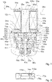
- the solenoid valve 10a is in a currentless state.
- the solenoid valve 10a is designed as a pressure-compensating solenoid valve.
- the solenoid valve 10a is designed as a 3/2-way valve.
- the solenoid valve 10a has a pressure-compensating solenoid valve device.
- the solenoid valve device has a magnet part 12a.
- the magnetic part 12a is provided for generating and/or controlling a magnetic field.
- the magnetic part 12a forms an independently functioning module 24a.
- the magnetic part 12a is free of movably mounted components.
- the magnetic part 12a has a magnetic coil winding 14a.
- the magnetic coil winding 14a is designed as a cylinder coil winding.
- the magnetic coil winding 14a forms a solenoid 78a.
- the magnetic coil winding 14a forms an electromagnetic coil.
- the magnet part 12a has a winding carrier 60a.
- the winding carrier 60a is made of a non-conductive and/or non-magnetizable plastic.
- the magnetic coil winding 14a is wound around the bobbin 60a.
- the magnetic coil winding 14a and/or the solenoid 78a includes an interior 16a.
- the interior 16a of the magnetic coil winding 14a has a magnetic core 18a.
- the magnetic core 18a forms a partially broken iron circuit.
- the magnetic core 18a is arranged at least in a center of the solenoid 78a. Alternatively, the interior 16a of the magnet coil winding 14a and/or the entire magnet part 12a can be designed without a magnet core 18a.
- the magnetic part 12a includes a magnetic circuit 80a.
- the magnetic circuit 80a is at least partially made of a ferromagnetic and/or a soft magnetic material, in particular iron.
- Of the Magnetic circuit 80a includes magnetic core 18a.
- the magnetic circuit 80a includes a magnetic bracket 68a.
- the magnet bracket 68a at least partially encloses the magnet coil winding 14a.
- the magnetic circuit 80a, in particular the magnetic bracket 68a can alternatively or additionally be designed at least partially as a round magnet housing.
- the magnetic circuit 80a includes a magnetic yoke 62a. Magnet yoke 62a at least partially encloses magnet coil winding 14a.
- the components 18a, 62a, 68a of the magnetic circuit 80a are designed as separate elements. Alternatively, the components 18a, 62a, 68a of the magnetic circuit 80a could be formed in one piece with one another.
- the magnetic circuit 80a is formed as an open magnetic circuit.
- the magnetic circuit 80a has a gap 84a.
- the magnetic circuit 80a has another gap 86a.
- the gap 84a of the magnetic circuit 80a is at least partially filled by the winding carrier 60a.
- the further gap 86a of the magnetic circuit 80a is at least partially filled by the winding carrier 60a.
- the gaps 84a, 86a in combination with the iron circuit of the magnetic circuit 80a create an inductance of the magnetic circuit 80a.
- the magnetic part 12a has a connection device 54a.
- the connecting device 54a forms a plug connection.
- the connection device 54a is provided for an electrical connection of the magnetic coil winding 14a.
- the solenoid valve device has a control device 56a.
- the control device 56a is provided for controlling a power supply of the magnetic part 12a.
- the control device 56a is provided for controlling a magnetic field of the magnetic coil winding 14a.
- the control device 56a is provided for controlling the magnetic valve 10a by means of the magnetic field of the magnetic coil winding 14a.
- the solenoid valve device has a valve part 22a.
- the valve part 22a forms an independently functioning module 26a.
- the valve part 22a has a tappet unit 20a.
- the plunger unit 20a is provided to control a flow path through the solenoid valve 10a.
- the plunger unit 20a is intended to interact with a magnetic field generated within the magnetic part 12a.
- the interaction of the tappet unit 20a with the magnetic field of the magnetic part 12a is intended to generate a movement of the tappet unit 20 .
- the tappet unit 20a is intended to move towards the magnetic part 12a when the magnetic field is activated.
- the plunger unit 20a is intended to minimize the inductance of the magnetic circuit 80a by means of a movement in the direction of the gaps 84a, 86a of the magnetic circuit 80a of the magnetic part 12a.
- the tappet unit 20a is pulled by the magnetic field in the direction of the gaps 84a, 86a.
- the valve part 22a has a housing 34a.
- the housing 34a forms a valve housing.
- the plunger unit 20a is movably mounted in the housing 34a.
- the housing 34a is designed in several parts. Separately formed sub-units of the housing 34a are sealed in a pressure-tight manner. Alternatively, the housing 34 could be formed in one piece.
- the valve part 22a includes a guide element 66a.
- the guide element 66a is provided for guiding the tappet unit 20a within the valve part 22a.
- the housing 34a has a pressure port 36a.
- the pressure connection 36a is designed as a housing opening.
- the pressure connection 36a is arranged on a side of the mounted magnet valve device which faces away from the magnet part 12a.
- the housing 34a has a working connection 38a.
- the working connection 38a is designed as a housing opening.
- the housing 34a has a vent port 40a.
- the vent port 40a is formed as a case opening.
- the valve part 22a has a sealing arrangement 42a.
- the pressure connection 36a is sealed off from the working connection 38a by means of the sealing arrangement 42a.
- the pressure connection 36a is sealed off from the ventilation connection 40a by means of the sealing arrangement 42a.
- the sealing arrangement 42a has a seal 44a.
- the seal 44a of the seal arrangement 42a is designed as a sliding seal 72a.
- the seal 44a of the seal arrangement 42a has a seal diameter 46a.
- the solenoid valve device has a valve seal 64a.
- the valve seal 64a is intended to close or open specific flow paths.
- the valve part 22a has a first valve seat 50a.
- the valve seal 64a is provided to sit sealingly on the first valve seat 50a. When the valve seal 64a sits tightly on the first valve seat 50a, the pressure connection 36a is closed. When the valve seal 64a sits tightly on the first valve seat 50a, a path is opened between the working connection 38a and the ventilation connection 40a.
- the first valve seat 50a has an effective diameter 48a.
- the effective diameter 48a of the first valve seat 50a corresponds at least essentially to the seal diameter 46a of the seal 44a of the seal arrangement 42a.
- the valve part 22a has a second valve seat 52a.
- the first valve seat 50a is in 1 shown configuration of the solenoid valve 10a occupied in the de-energized state.
- the second valve seat 52a is in the in 1 shown configuration of the solenoid valve 10a unoccupied in the de-energized state.
- the second valve seat 52a has an effective diameter 88a.
- the effective diameter 88a of the second valve seat 52a corresponds at least essentially to the effective diameter 48a of the first valve seat 50a.
- the effective diameter 88a of the second valve seat 52a corresponds at least essentially to the seal diameter 46a of the seal 44a of the seal arrangement 42a.
- the solenoid valve 10a forms a 3/2 NC solenoid valve.
- the solenoid valve 10a could form a 3/2 NO solenoid valve if the pressure connection 36a and the ventilation connection 40a were interchanged.
- the solenoid valve 10a could close the Vent port 40a form a 2/2 NC solenoid valve.
- the solenoid valve 10a could form a 2/2 NO solenoid valve when the pressure port 36a is closed and when the working port 38a and the vent port 40a are interchanged and/or when the vent port 40a is closed.
- the ram unit 20a has an armature ram 90a.
- the armature tappet 90a is made of a ferromagnetic and/or a soft magnetic material.
- the armature tappet 90a is formed in one piece. Alternatively, the armature tappet 90a could be made in several parts.
- the tappet unit 20a has the valve seal 64a.
- the valve seal 64a is pressed onto the armature tappet 90a.
- the tappet unit 20a forms a flat armature 70a.
- the armature tappet 90a forms the flat armature 70a.
- the flat armature 70a has a disc-shaped end area 82a.
- the disk-shaped end region 82a is arranged on a side of the armature tappet 90a that faces the magnetic part 12a.
- the disc-shaped end area 82a is arranged in the vicinity of the gaps 84a, 86a of the magnetic circuit 80a of the magnetic part 12a. Due to the inductance of the gaps 84a, 86a, the disk-shaped end region 82a of the armature tappet 90a is pulled in the direction of the magnet part 12a when the magnet coil winding 14a is energized.
- the tappet unit 20a has a pressure compensation element 30a.
- the pressure compensation element 30a is designed as a bore in the center of the tappet unit 20a, in particular the armature tappet 90a.
- the pressure compensation element 30a is provided for setting an at least essentially identical pressure on the side of the plunger unit 20a facing the magnet part 12a as on the side facing the pressure connection 36a.
- the plunger unit 20a has a restoring element 32a.
- the restoring element 32a is designed as a compression spring.
- the restoring element 32a is supported against the magnetic part 12a.
- the return element 32a is directly against the Magnetic core 18a of the magnetic part 12a is supported.
- the restoring element 32a is intended to push the plunger unit 20a away from the magnetic part 12a.
- the restoring element 32a is arranged partially within the pressure compensation element 30a.
- the pressure compensation element 30a has a receiving area 100a.
- the receiving area 100a of the pressure equalization element 30a is designed as a widening of the pressure equalization element 30a in sections.
- the receiving area 100a of the pressure compensation element 30a forms a shoulder 102a.
- the restoring element 32a is supported against the shoulder 102a of the pressure compensation element 30a.
- the magnetic part 12a and the valve part 22a form separable modules 24a, 26a.
- the magnetic part 12a and the valve part 22a form independently functional modules 24a, 26a.
- the modules 24a, 26a formed by the magnetic part 12a and the valve part 22a have no common functional components.
- the valve part 22a is at least essentially free of components that at least partially engage in the magnet part 12a in at least one operating state.
- the magnet part 12a is at least essentially free of components that at least partially engage in the valve part 22a in at least one operating state.
- the magnet part 12a and the valve part 22a can be coupled to one another.
- the magnet part 12a and the valve part 22a can be captively coupled to one another.
- the module 24a which is formed by the magnetic part 12a and is coupled to the valve part 22a, can be decoupled from the valve part 22a in a non-destructive manner.
- the magnet part 12a and the valve part 22a are at least essentially thermally decoupled from one another.
- the magnet part 12a and the valve part 22a are at least essentially thermally decoupled from one another in a coupled state.
- the valve part 22a has a sealing and mounting device 28a.
- the magnetic part 12a has the sealing and mounting device 28a.
- the sealing and assembly device 28a is intended to provide a coupling of the To produce valve part 22a formed module 26a and the module 24a formed by the magnetic part 12a.
- the sealing and assembly device 28a has corresponding coupling elements 92a, 94a.
- a coupling element 92a of the sealing and assembly device 28a is assigned to the valve part 22a.
- Another coupling element 94a is assigned to the magnetic part 12a.
- the corresponding coupling elements 92a, 94a form a positive connection.
- the sealing and assembly device 28a forms a detachable, captive and tight coupling of the magnetic part 12a with the valve part 22a.
- the sealing and assembly device 28a has a sealing element 96a.
- the sealing element 96a is provided to produce a pressure-tight coupling between the magnet part 12a and the valve part 22a.
- the sealing element 96a is provided to seal a cavity 104a of the valve part 22a, which is connected to the pressure connection 36a via the pressure equalization element 30a, in a pressure-tight manner to the outside by resting against the magnet part 12a.
- the sliding seal 72a includes the sealing ring 76a.
- the sealing ring 76a is made of an elastomer.
- the sealing ring 76a has a surface coating 110a.
- the surface coating 110a forms a thin layer 74a.
- the thin layer 74a is formed of a polytetrafluoroethylene.
- the thin layer 74a is provided to reduce surface friction of the sliding seal 72a.
- the thin layer 74a is provided to increase wear resistance of the sliding seal 72a.
- the sealing ring 76a has a V-shaped groove 112a.
- the groove 112a is provided to advantageously improve dynamic properties of the sealing ring 76a when the tappet unit 20a moves.
- the magnetic valve system 58a forms a modular system, in particular a modular magnetic valve system.
- the magnetic valve system 58a comprises a plurality of magnetic parts 12a, 12a', 12a'' which each form independent modules 24a.
- the magnetic parts 12a, 12a', 12a'' of the magnetic valve system 58a are designed differently from each other.
- the magnet parts 12a, 12a′, 12a′′, which are designed differently from one another, have different connection devices 54a, 54a′, 54a′′. At least some of the magnet parts 12a, 12a', 12a" of the magnet valve system 58a are identical to one another.
- the magnet valve system 58a comprises a plurality of valve parts 22a, 22a', 22a", 22a′′′, each of which forms independent modules 26a.
- the valve parts 22a, 22a', 22a", 22a′′′ of the solenoid valve system 58a are designed differently from one another.
- the differently designed valve parts 22a, 22a', 22a", 22a′′′ have different arrangements and/or dimensions of working connections 38a, 38a', pressure connections 36a, 36a' and/or ventilation connections 40a, 40a'.
- At least some of the valve parts 22a, 22a', 22a", 22a′′′ of the solenoid valve system 58a are identical to one another.
- the solenoid parts 12a, 12a', 12a" of the solenoid valve system 58a are interchangeable with the valve parts 22a, 22a', 22a", 22a′′′ Any magnet parts 12a, 12a', 12a” can be coupled with any valve parts 22a, 22a', 22a", 22a′′′ of the magnet valve system 58a.
- One magnet part 12a, 12a', 12a" and one with the magnet part 12a, 12a', 12a" coupled valve part 22a, 22a', 22a", 22a′′′ form a magnetic valve 10a, 10a', 10a".
- valve parts 22a, 22a', 22a", 22a′′′ and the magnetic parts 12a, 12a', 12a" of the magnetic valves 10a, 10a', 10a” can be decoupled and/or exchanged without being destroyed.
- Solenoid valves 10a, 10a', 10a" can be coupled together to form a valve chain 106a.
- the pressure connections 36a of the solenoid valves 10a in 3 Valve chain 106a shown as an example are connected to a common pressure line 108a.
- FIG. 4 shows a flowchart of a method with the solenoid valve device for the pressure-balanced solenoid valve 10a.
- a magnet part 12a and a valve part 22a are selected for coupling to form a magnet valve 10a.
- the selected magnet part 12a is connected to the selected one by means of the sealing and assembly device 28a Valve part 22a connected.
- the connection created in method step 116a between the magnet part 12a and the valve part 22a can be released.
- the connection created in method step 116a between the magnet part 12a and the valve part 22a is pressure-tight.
- connection created in method step 116a between the magnet part 12a and the valve part 22a connects the magnet part 12a and the valve part 22a to one another in a captive manner.
- the corresponding coupling elements 92a, 94a are brought into positive engagement with one another.
- the tappet unit 20a of the coupled valve part 22a is moved by a magnetic field generated by the magnet coil winding 14a of the magnet part 12a to switch the magnet valve 10a.
- the tappet unit 20a is pulled by the magnetic field in the direction of the magnet part 12a.
- the tappet unit 20a is deflected back by the restoring element 32a.
- the plunger unit 20a is pushed away from the magnetic part 12a by the restoring element 32a.
- the magnetic part 12a is decoupled from the valve part 22a in a non-destructive manner.
- the magnetic part 12a is replaced by a further magnetic part 12a, 12a', 12a" that is different from the magnetic part 12a and/or the valve part 22a is replaced by a further valve part 22a, 22a', 22a", that is different from the valve part 22a. 22a′′′ exchanged.
- the replaced additional magnet part 12a, 12a', 12a" is coupled to the remaining valve part 22a and/or the replaced additional valve part 22a, 22a', 22a", 22a′′′ is coupled to the remaining magnet part 12a.
- figure 5 10 shows an alternative solenoid valve 10b with an alternative solenoid valve device.
- the magnetic valve device has a magnetic part 12b and a valve part 22b.
- the magnet part 12b is hermetically overmoulded.
- the magnet part 12b has a magnet part housing 98b.
- the hermetic encapsulation of the magnet part 12b forms the magnet part housing 98b.
- the magnet part housing 98b is intended to shield the magnet part 12b from external influences, for example dirt or moisture.
- the valve part 22b has a housing 34b.
- the housing 34b of the valve part 22b and the magnet part housing 98b are connected to form the magnet valve 10b.
- the valve part 22b has a tappet unit 20b.
- the plunger unit 20b is intended to be moved by means of a magnetic field of the magnetic part 12b to actuate the magnetic valve 10b.
- the valve part 22b has a restoring element 32b.
- the restoring element 32b is provided to return the tappet unit 20b to an initial state when the magnetic field of the magnetic part 12b is switched off.
- the restoring element 32b is supported on the magnet part housing 98b.
- the magnet part housing 98b has a small thickness of a few millimeters.
- the magnet part housing 98b only slightly influences a transmission of the magnetic field from the magnet part 12b to the tappet unit 20b, in particular a magnetic field strength at the location of the tappet unit 20b is less than 5%, preferably less than 3% and preferably less than 1% lower than a magnetic field strength of an identical magnet part 12b, which has no magnet part housing 98b.
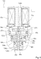
- the solenoid valve device has a Magnetic part 12c and a valve part 22c.
- the valve part 22c has a tappet unit 20c.
- the tappet unit 20c is intended to be moved by means of a magnetic field of the magnetic part 12c to actuate the magnetic valve 10c.
- the ram unit 20c has an armature ram 90c.
- the armature tappet 90c forms a flat armature 70c.
- the solenoid valve assembly includes a first valve seal 64c.
- the tappet assembly 20c includes the first valve seal 64c.
- the first valve seal 64c is pressed onto the armature tappet 90c.
- the solenoid valve assembly includes a second valve seal 128c.
- the tappet unit 20c has the second valve seal 128c.
- the second valve seal 128c is pressed onto the armature tappet 90c.
- the first valve seal 64c is spaced from the second valve seal 128c along an axis of movement 130c of the plunger assembly 20c.
- the first valve seal 64a is arranged behind the second valve seal 128c, viewed in the direction of the magnetic part 12c.
- the first valve seal 64c is arranged between the second valve seal 128c and the magnetic part 12c.
- the first valve seal 64c is spatially separate from the second valve seal 128c. Apart from the armature tappet 90c, the first valve seal 64c and the second valve seal 128c are free of a common carrier element.
- the first valve seal 64c moves with the second valve seal 128c and vice versa.
- the first valve seal 64c and the second valve seal 128c are provided to block and/or unblock different flow paths through the solenoid valve device.
- the valve part 22c has a first valve seat 50c.
- the valve part 22a has a housing 34c.
- the housing 34c has a pressure port 36c.
- the pressure connection 36c is arranged in the vicinity of the second valve seal 128c and/or a second valve seat 52c.
- the housing 34c has a working connection 38c.
- the working connection 38c is arranged in an intermediate region 134c between the first valve seal 64c and the second valve seal 128c.
- the housing 34c has a vent port 40c.
- the vent port 40c is in one Arranged in the vicinity of the first valve seal 64c, the first valve seat 50c and/or a third valve seat 132c.
- the first valve seal 64c is intended to sit sealingly on the first valve seat 50c in at least one operating state.
- the second valve seal 128c does not unseat in any operating condition of the solenoid valve assembly 6 on the first valve seat 50c.
- a sealing seat of the first valve seal 64c on the first valve seat 50c is in the embodiment of 6 the vent port 40c is closed.
- the valve part 22c has the second valve seat 52c.
- the second valve seal 128c is intended to sit sealingly on the second valve seat 52c in at least one operating state.
- the first valve seal 64c does not unseat in any operating condition of the solenoid valve assembly 6 sealingly on the second valve seat 52c.
- the valve part 22c has the third valve seat 132c.
- the first valve seal 64c is provided to sit sealingly on the third valve seat 132c in at least one operating state.
- the second valve seal 128c does not unseat in any operating condition of the solenoid valve assembly 6 on the third valve seat 132c.
- a connection of at least the ventilation connection 40c and/or at least the working connection 38c to a hollow space 104c on the magnet part side, in which in particular the flat armature 70c is arranged is closed.
- Cavity 104c is advantageously connected to pressure connection 36c and/or to pressure connection 36c via a pressure compensation element 30c of tappet unit 20c open.
- the design of 6 is free of a sliding seal, in particular a seal sliding along the tappet unit 20c.
- the solenoid valve device from 6 has at least essentially identical, in particular at least essentially identically arranged valve connections, ie the pressure connection 36c, the working connection 38c and the ventilation connection 40c. As a result, an exchangeability of different valve parts 22c can advantageously be made possible or maintained.
Landscapes
- Engineering & Computer Science (AREA)
- General Engineering & Computer Science (AREA)
- Mechanical Engineering (AREA)
- Physics & Mathematics (AREA)
- Electromagnetism (AREA)
- Fluid Mechanics (AREA)
- Transportation (AREA)
- Magnetically Actuated Valves (AREA)
Claims (18)
- Dispositif d'électrovanne pour une électrovanne pressurisée (10a, 10a', 10a" ; 10b, 10c), en particulier dispositif d'électrovanne pressurisant,avec un élément aimant (12a, 12a', 12a" ; 12b, 12c) comprenant au moins un enroulement de bobine d'électroaimant (14a ; 14b, 14c) et de préférence au moins un noyau d'aimant (18a ; 18b, 18c) disposé au moins partiellement dans un intérieur (16a ; 16b, 16c) de l'enroulement de bobine d'électroaimant (14a ; 14b, 14c),et avec un élément vanne (22a, 22a', 22a", 22a‴ ; 22b, 22c) comprenant au moins une unité de poussoir (20a ; 20b, 20c) qui est configurée au moins pour commander au moins un chemin de passage à travers l'électrovanne (10a, 10a', 10a" ; 10b, 10c) et qui est au moins configurée pour interagir avec un champ magnétique, généré dans l'élément aimant (12a, 12a', 12a" ; 12b, 12c), au moins pour générer au moins un mouvement de l'unité de poussoir (20a ; 20b, 20c),caractérisé en ce que l'élément aimant (12a, 12a', 12a" ; 12b, 12c) et l'élément vanne (22a, 22a', 22a", 22a‴ ; 22b, 22c) forment des modules (24a, 26a ; 24b, 26b, 24c, 26c) qui sont séparables et capables de fonctionner indépendamment l'un de l'autre, qui sont en particulier libres de composants fonctionnels communs, comme par exemple une armature magnétique commune,l'élément aimant (12a, 12a', 12a" ; 12b, 12c) étant au moins sensiblement libre de composants supportés de façon mobile et/ou de composants qui au moins partiellement s'engrènent dans l'élément vanne (22a, 22a', 22a", 22a‴ ; 22b, 22c) en au moins un état de fonctionnement.
- Dispositif d'électrovanne selon la revendication 1,
caractérisé en ce que l'élément vanne (22a, 22a', 22a", 22a‴ ; 22b, 22c) est au moins sensiblement libre de composants qui au moins partiellement s'engrènent dans l'élément aimant (12a, 12a', 12a" ; 12b, 12c) en au moins un état de fonctionnement. - Dispositif d'électrovanne selon l'une des revendications précédentes,
caractérisé en ce que l'élément vanne (22a, 22a', 22a", 22a‴ ; 22b, 22c) et/ou l'élément aimant (12a, 12a', 12a" ; 12b, 12c) comprennent/comprend un dispositif d'étanchéité et montage (28a ; 28b, 28c) qui est configuré pour produire un couplage du module (26a ; 26b, 26c) formé par l'élément vanne (22a, 22a', 22a", 22a‴ ; 22b, 22c) et du module (24a ; 24b, 24c) formé par l'élément aimant (12a, 12a', 12a" ; 12b, 12c). - Dispositif d'électrovanne selon la revendication 3,
caractérisé en ce qu'au moins le module (24a ; 24b, 24c) formé par l'élément aimant (12a, 12a', 12a" ; 12b, 12c) et couplé avec l'élément vanne (22a, 22a', 22a", 22a‴ ; 22b, 22c) peut être découplé de l'élément vanne (22a, 22a', 22a", 22a‴ ; 22b, 22c) sans déstruction. - Dispositif d'électrovanne selon l'une des revendications précédentes,
caractérisé en ce que l'unité de poussoir (20a ; 20b, 20c) forme au moins une armature plate (70a ; 70b, 70c). - Dispositif d'électrovanne selon l'une des revendications précédentes,
caractérisé en ce que l'unité de poussoir (20a ; 20b, 20c) comporte au moins un élément de pressurisation (30a ; 30b, 30c). - Dispositif d'électrovanne selon l'une des revendications précédentes,
caractérisé en ce que l'unité de poussoir (20a ; 20b, 20c) comprend au moins un élément de rappel (32a ; 32b, 32c) qui est supporté contre l'élément aimant (12a, 12a', 12a" ; 12b, 12c). - Dispositif d'électrovanne selon les revendications 6 et 7,
caractérisé en ce que l'élément de rappel (32a ; 32b, 32c) est disposé au moins partiellement dans l'élément de pressurisation (30a ; 30b, 30c). - Dispositif d'électrovanne selon l'une des revendications précédentes,caractérisé en ce que l'élément vanne (22a, 22a', 22a", 22a‴ ; 22b, 22c) comprend au moins un boîtier (34a ; 34b ; 34c) avec au moins un raccord de pression (36a, 36a' ; 36b, 36c), au moins un raccord de travail (38a, 38a' ; 38b, 38c) et/ou au moins un raccord d'aération (40a, 40a' ; 40b, 40c),le raccord de pression (36a, 36a' ; 36b, 36c) étant scellé contre le raccord de travail (38a, 38a' ; 38b, 38c) et/ou le raccord d'aération (40a, 40a' ; 40b, 40c) au moins par le biais d'un arrangement de scellage (42a ; 42b, 42c).
- Dispositif d'électrovanne selon la revendication 9,
caractérisé en ce que l'au moins une étanchéité (44a ; 44b) de l'arrangement de scellage (42a ; 42b, 42c) présente un diamètre d'étanchéité (46a ; 46b) correspondant au moins sensiblement à un diamètre effectif (48a ; 48b) d'au moins un siège de vanne (50a, 52a ; 50b, 52b) de l'élément vanne (22a, 22a', 22a", 22a‴ ; 22b, 22c). - Dispositif d'électrovanne selon la revendication 9 ou 10,
caractérisé en ce que l'arrangement de scellage (42a ; 42b) comporte au moins une étanchéité glissante (72a ; 72b). - Dispositif d'électrovanne selon la revendication 11,
caractérisé en ce que l'étanchéité glissante (72a ; 72b) comporte une bague d'étanchéité (76a ; 76b) qui est formée au moins en grande partie d'un élastomère, ledit élastomère comprenant une mince couche (74a ; 74b) de polytétrafluoroethy-lène. - Dispositif d'électrovanne selon l'une des revendications précédentes,
caractérisé en ce qu'au moins l'élément aimant (12a, 12a', 12a" ; 12b, 12c) est surmoulé hermétiquement. - Dispositif d'électrovanne selon l'une des revendications précédentes,
caractérisé en ce que l'unité de poussoir (20c) comprend au moins une première étanchéité vanne (64c) et au moins une deuxième étanchéité vanne (128c) qui est en particulier écartée de la première étanchéité vanne (64c) le long d'un axe de mouvement (130c) de l'unité de poussoir (20c), les étanchéités vanne (64c, 128c) étant configurées pour respectivement bloquer et/ou liberer des chemins de passage différents à travers l'électrovanne (10c). - Électrovanne pressurisée (10a, 10a', 10a" ; 10b, 10c) avec un dispositif d'électrovanne selon l'une des revendications précédentes,
caractérisé par une formation comme vanne 3/2 NO, comme vanne 3/2 NC, comme vanne 2/2 NO ou comme vanne 2/2 NC. - Système d'électrovanne (58a ; 58b, 58c) avec un dispositif d'électrovanne selon l'une des revendications 1 à 14 et/ou avec une électrovanne (10a, 10a', 10a" ; 10b, 10c) selon la revendication 15,avec une pluralité d'éléments aimant (12a, 12a', 12a") qui sont au moins partiellement réalisés différant l'un de l'autre, qui peuvent être couplés échangeablement avec l'élément vanne (22a, 22a', 22a", 22a‴ ; 22b, 22c) et qui sont réalisés comme module séparable (24a ; 24b, 24c), et/ouavec une pluralité d'éléments vanne (22a, 22a', 22a", 22a‴ ; 22b, 22c) qui sont au moins partiellement réalisés différant l'un de l'autre, qui peuvent être couplés échangeablement avec l'élément aimant (12a, 12a', 12a" ; 12b, 12c) et qui sont réalisés comme module séparable (26a ; 26b, 26c).
- Élément aimant (12a, 12a', 12a" ; 12b, 12c) du dispositif d'électrovanne selon l'une des revendications 1 à 14 et/ou de l'électrovanne (10a, 10a', 10a" ; 10b, 10c) selon la revendication 15.
- Élément vanne (22a, 22a', 22a", 22a‴ ; 22b, 22c) du dispositif d'électrovanne selon l'une des revendications 1 à 14 et/ou de l'électrovanne (10a, 10a', 10a" ; 10b, 10c) selon la revendication 15.
Applications Claiming Priority (2)
| Application Number | Priority Date | Filing Date | Title |
|---|---|---|---|
| DE102018127573.0A DE102018127573A1 (de) | 2018-11-05 | 2018-11-05 | Magnetventilvorrichtung für ein druckausgeglichenes Magnetventil, ein druckausgeglichenes Magnetventil, Magnetventilsystem und Verfahren mit der Magnetventilvorrichtung |
| PCT/EP2019/079908 WO2020094507A1 (fr) | 2018-11-05 | 2019-10-31 | Dispositif d'électrovanne pour une électrovanne à pression équilibrée, électrovanne à pression équilibrée, système d'électrovanne et procédé avec le dispositif d'électrovanne |
Publications (2)
| Publication Number | Publication Date |
|---|---|
| EP3877679A1 EP3877679A1 (fr) | 2021-09-15 |
| EP3877679B1 true EP3877679B1 (fr) | 2022-10-26 |
Family
ID=68426500
Family Applications (1)
| Application Number | Title | Priority Date | Filing Date |
|---|---|---|---|
| EP19797708.5A Active EP3877679B1 (fr) | 2018-11-05 | 2019-10-31 | Ensemble de valve magnétique pour valve compensée en pression, valve compensée en pression |
Country Status (5)
| Country | Link |
|---|---|
| US (1) | US20210381616A1 (fr) |
| EP (1) | EP3877679B1 (fr) |
| CN (1) | CN113227617A (fr) |
| DE (1) | DE102018127573A1 (fr) |
| WO (1) | WO2020094507A1 (fr) |
Families Citing this family (3)
| Publication number | Priority date | Publication date | Assignee | Title |
|---|---|---|---|---|
| US11721465B2 (en) | 2020-04-24 | 2023-08-08 | Rain Bird Corporation | Solenoid apparatus and methods of assembly |
| EP4430325A1 (fr) * | 2021-11-08 | 2024-09-18 | ETO MAGNETIC GmbH | Système d'étanchéité pour fluide, circuit de fluide et procédé |
| CN118815955B (zh) * | 2024-08-28 | 2026-02-03 | 河南航天液压气动技术有限公司 | 一种两位三通电磁阀 |
Family Cites Families (12)
| Publication number | Priority date | Publication date | Assignee | Title |
|---|---|---|---|---|
| JPS5724378U (fr) * | 1980-07-11 | 1982-02-08 | ||
| DE3213007A1 (de) * | 1982-04-07 | 1983-10-20 | Robert Bosch Gmbh, 7000 Stuttgart | Antiblockierregelsystem |
| US4611631A (en) * | 1985-01-24 | 1986-09-16 | Shoketsu Kinzoku Kogyo Kabushiki Kaisha | Solenoid operated poppet type change-over valve |
| DE10002444B4 (de) * | 2000-01-21 | 2004-04-22 | Robert Bosch Gmbh | Hydraulisches Druckregelventil |
| DE10359364B4 (de) * | 2003-12-18 | 2012-10-11 | Schaeffler Technologies Gmbh & Co. Kg | Elektromagnetisches Hydraulikventil, insbesondere 3/2-Wegeschaltventil zur Steuerung eines varialblen Ventiltriebes einer Brennkraftmaschine |
| DE102005003446A1 (de) * | 2005-01-27 | 2006-08-10 | Schaeffler Kg | Elektromagnetisches Hydraulikventil |
| CN201090731Y (zh) * | 2007-08-27 | 2008-07-23 | 程麒 | 一种高压自润滑y形密封圈 |
| DE102009060030A1 (de) * | 2009-12-21 | 2011-06-22 | Robert Bosch GmbH, 70469 | Elektromagnetisch schaltbares Ventil zum Einbau in einen Einbaublock |
| US8783653B2 (en) * | 2012-12-21 | 2014-07-22 | Mac Valves, Inc. | Multi-port modular valve with snap-in seat |
| DE202013003049U1 (de) * | 2013-04-03 | 2013-05-06 | Bürkert Werke GmbH | Magnetventil, Batterie aus Magnetventilen sowie Werkzeug |
| CN204664563U (zh) * | 2015-05-07 | 2015-09-23 | 合肥美亚光电技术股份有限公司 | 电磁阀及具有该电磁阀的电磁阀组和电磁阀阵列 |
| DE102017000446B4 (de) * | 2017-01-19 | 2024-07-04 | Staiger Gmbh & Co. Kg | Ventil |
-
2018
- 2018-11-05 DE DE102018127573.0A patent/DE102018127573A1/de not_active Withdrawn
-
2019
- 2019-10-31 EP EP19797708.5A patent/EP3877679B1/fr active Active
- 2019-10-31 US US17/290,460 patent/US20210381616A1/en not_active Abandoned
- 2019-10-31 WO PCT/EP2019/079908 patent/WO2020094507A1/fr not_active Ceased
- 2019-10-31 CN CN201980086701.2A patent/CN113227617A/zh active Pending
Also Published As
| Publication number | Publication date |
|---|---|
| DE102018127573A1 (de) | 2020-05-07 |
| US20210381616A1 (en) | 2021-12-09 |
| CN113227617A (zh) | 2021-08-06 |
| EP3877679A1 (fr) | 2021-09-15 |
| WO2020094507A1 (fr) | 2020-05-14 |
Similar Documents
| Publication | Publication Date | Title |
|---|---|---|
| DE3309904C2 (fr) | ||
| DE69111628T2 (de) | Druckregler für Fluide. | |
| EP2004428B1 (fr) | Soupape de commande | |
| EP3877679B1 (fr) | Ensemble de valve magnétique pour valve compensée en pression, valve compensée en pression | |
| DE69715712T2 (de) | Hydraulisches Elektromagnetventil | |
| EP0188673A2 (fr) | Soupape à voies multiples commandée par électro-aimant | |
| EP3359415A1 (fr) | Répartiteur de pression pour véhicule automobile | |
| EP3526087B1 (fr) | Électrovanne et système de freinage hydraulique pour véhicule | |
| EP1124714A1 (fr) | Dispositif electromagnetique, notamment destine a un systeme de freinage hydraulique et anti-patinage d'un vehicule | |
| DE602004006563T2 (de) | Magnetischer Betätiger | |
| EP1031731A2 (fr) | Soupape à voies multiples à siège | |
| DE3227613A1 (de) | Magnetluftventil | |
| EP0846902B1 (fr) | Vanne électropneumatique | |
| WO2008040618A1 (fr) | Soupape de réglage de pression | |
| DE102004015661B4 (de) | Elektropneumatisches Ventil, insbesondere Vorsteuerventil für ein pneumatisches Wegeventil | |
| DE10241449A1 (de) | Elektromagnetisches Druckregelventil | |
| DE102019131851A1 (de) | Ventil sowie Ventilinsel | |
| DE4317706A1 (de) | Fremdkraftbetätigtes Wege-Sitzventil | |
| DE10146497A1 (de) | Elektromagnetisches Steuerventil | |
| EP1737715B1 (fr) | Electrovanne | |
| EP0506895B1 (fr) | Systeme de regulation de la puissance de freinage avec dispositif de coupure a commande electrique | |
| EP3563076B1 (fr) | Dispositif de vanne électromagnétique à armature basculante | |
| EP0182053A1 (fr) | Vanne de régulation de pression électromagnétiquement commandée | |
| DE8806867U1 (de) | Elektromagnetisch betätigbares 5/2-Wegeventil | |
| EP3643954A1 (fr) | Soupape électromagnétique, procédé de fonctionnement d'une soupape électromagnétique |
Legal Events
| Date | Code | Title | Description |
|---|---|---|---|
| STAA | Information on the status of an ep patent application or granted ep patent |
Free format text: STATUS: UNKNOWN |
|
| STAA | Information on the status of an ep patent application or granted ep patent |
Free format text: STATUS: THE INTERNATIONAL PUBLICATION HAS BEEN MADE |
|
| PUAI | Public reference made under article 153(3) epc to a published international application that has entered the european phase |
Free format text: ORIGINAL CODE: 0009012 |
|
| STAA | Information on the status of an ep patent application or granted ep patent |
Free format text: STATUS: REQUEST FOR EXAMINATION WAS MADE |
|
| 17P | Request for examination filed |
Effective date: 20210531 |
|
| AK | Designated contracting states |
Kind code of ref document: A1 Designated state(s): AL AT BE BG CH CY CZ DE DK EE ES FI FR GB GR HR HU IE IS IT LI LT LU LV MC MK MT NL NO PL PT RO RS SE SI SK SM TR |
|
| DAV | Request for validation of the european patent (deleted) | ||
| DAX | Request for extension of the european patent (deleted) | ||
| GRAP | Despatch of communication of intention to grant a patent |
Free format text: ORIGINAL CODE: EPIDOSNIGR1 |
|
| STAA | Information on the status of an ep patent application or granted ep patent |
Free format text: STATUS: GRANT OF PATENT IS INTENDED |
|
| INTG | Intention to grant announced |
Effective date: 20220512 |
|
| GRAS | Grant fee paid |
Free format text: ORIGINAL CODE: EPIDOSNIGR3 |
|
| GRAA | (expected) grant |
Free format text: ORIGINAL CODE: 0009210 |
|
| STAA | Information on the status of an ep patent application or granted ep patent |
Free format text: STATUS: THE PATENT HAS BEEN GRANTED |
|
| AK | Designated contracting states |
Kind code of ref document: B1 Designated state(s): AL AT BE BG CH CY CZ DE DK EE ES FI FR GB GR HR HU IE IS IT LI LT LU LV MC MK MT NL NO PL PT RO RS SE SI SK SM TR |
|
| REG | Reference to a national code |
Ref country code: GB Ref legal event code: FG4D Free format text: NOT ENGLISH |
|
| REG | Reference to a national code |
Ref country code: CH Ref legal event code: EP |
|
| REG | Reference to a national code |
Ref country code: DE Ref legal event code: R096 Ref document number: 502019006063 Country of ref document: DE |
|
| REG | Reference to a national code |
Ref country code: AT Ref legal event code: REF Ref document number: 1527249 Country of ref document: AT Kind code of ref document: T Effective date: 20221115 |
|
| REG | Reference to a national code |
Ref country code: IE Ref legal event code: FG4D Free format text: LANGUAGE OF EP DOCUMENT: GERMAN |
|
| REG | Reference to a national code |
Ref country code: LT Ref legal event code: MG9D |
|
| REG | Reference to a national code |
Ref country code: NL Ref legal event code: MP Effective date: 20221026 |
|
| PG25 | Lapsed in a contracting state [announced via postgrant information from national office to epo] |
Ref country code: NL Free format text: LAPSE BECAUSE OF FAILURE TO SUBMIT A TRANSLATION OF THE DESCRIPTION OR TO PAY THE FEE WITHIN THE PRESCRIBED TIME-LIMIT Effective date: 20221026 |
|
| PG25 | Lapsed in a contracting state [announced via postgrant information from national office to epo] |
Ref country code: SE Free format text: LAPSE BECAUSE OF FAILURE TO SUBMIT A TRANSLATION OF THE DESCRIPTION OR TO PAY THE FEE WITHIN THE PRESCRIBED TIME-LIMIT Effective date: 20221026 Ref country code: PT Free format text: LAPSE BECAUSE OF FAILURE TO SUBMIT A TRANSLATION OF THE DESCRIPTION OR TO PAY THE FEE WITHIN THE PRESCRIBED TIME-LIMIT Effective date: 20230227 Ref country code: NO Free format text: LAPSE BECAUSE OF FAILURE TO SUBMIT A TRANSLATION OF THE DESCRIPTION OR TO PAY THE FEE WITHIN THE PRESCRIBED TIME-LIMIT Effective date: 20230126 Ref country code: LT Free format text: LAPSE BECAUSE OF FAILURE TO SUBMIT A TRANSLATION OF THE DESCRIPTION OR TO PAY THE FEE WITHIN THE PRESCRIBED TIME-LIMIT Effective date: 20221026 Ref country code: FI Free format text: LAPSE BECAUSE OF FAILURE TO SUBMIT A TRANSLATION OF THE DESCRIPTION OR TO PAY THE FEE WITHIN THE PRESCRIBED TIME-LIMIT Effective date: 20221026 Ref country code: ES Free format text: LAPSE BECAUSE OF FAILURE TO SUBMIT A TRANSLATION OF THE DESCRIPTION OR TO PAY THE FEE WITHIN THE PRESCRIBED TIME-LIMIT Effective date: 20221026 |
|
| PG25 | Lapsed in a contracting state [announced via postgrant information from national office to epo] |
Ref country code: RS Free format text: LAPSE BECAUSE OF FAILURE TO SUBMIT A TRANSLATION OF THE DESCRIPTION OR TO PAY THE FEE WITHIN THE PRESCRIBED TIME-LIMIT Effective date: 20221026 Ref country code: PL Free format text: LAPSE BECAUSE OF FAILURE TO SUBMIT A TRANSLATION OF THE DESCRIPTION OR TO PAY THE FEE WITHIN THE PRESCRIBED TIME-LIMIT Effective date: 20221026 Ref country code: LV Free format text: LAPSE BECAUSE OF FAILURE TO SUBMIT A TRANSLATION OF THE DESCRIPTION OR TO PAY THE FEE WITHIN THE PRESCRIBED TIME-LIMIT Effective date: 20221026 Ref country code: IT Free format text: LAPSE BECAUSE OF NON-PAYMENT OF DUE FEES Effective date: 20221031 Ref country code: IS Free format text: LAPSE BECAUSE OF FAILURE TO SUBMIT A TRANSLATION OF THE DESCRIPTION OR TO PAY THE FEE WITHIN THE PRESCRIBED TIME-LIMIT Effective date: 20230226 Ref country code: HR Free format text: LAPSE BECAUSE OF FAILURE TO SUBMIT A TRANSLATION OF THE DESCRIPTION OR TO PAY THE FEE WITHIN THE PRESCRIBED TIME-LIMIT Effective date: 20221026 Ref country code: GR Free format text: LAPSE BECAUSE OF FAILURE TO SUBMIT A TRANSLATION OF THE DESCRIPTION OR TO PAY THE FEE WITHIN THE PRESCRIBED TIME-LIMIT Effective date: 20230127 |
|
| REG | Reference to a national code |
Ref country code: CH Ref legal event code: PL |
|
| REG | Reference to a national code |
Ref country code: BE Ref legal event code: MM Effective date: 20221031 |
|
| PG25 | Lapsed in a contracting state [announced via postgrant information from national office to epo] |
Ref country code: LU Free format text: LAPSE BECAUSE OF NON-PAYMENT OF DUE FEES Effective date: 20221031 |
|
| REG | Reference to a national code |
Ref country code: DE Ref legal event code: R097 Ref document number: 502019006063 Country of ref document: DE |
|
| PG25 | Lapsed in a contracting state [announced via postgrant information from national office to epo] |
Ref country code: SM Free format text: LAPSE BECAUSE OF FAILURE TO SUBMIT A TRANSLATION OF THE DESCRIPTION OR TO PAY THE FEE WITHIN THE PRESCRIBED TIME-LIMIT Effective date: 20221026 Ref country code: RO Free format text: LAPSE BECAUSE OF FAILURE TO SUBMIT A TRANSLATION OF THE DESCRIPTION OR TO PAY THE FEE WITHIN THE PRESCRIBED TIME-LIMIT Effective date: 20221026 Ref country code: MC Free format text: LAPSE BECAUSE OF FAILURE TO SUBMIT A TRANSLATION OF THE DESCRIPTION OR TO PAY THE FEE WITHIN THE PRESCRIBED TIME-LIMIT Effective date: 20221026 Ref country code: LI Free format text: LAPSE BECAUSE OF NON-PAYMENT OF DUE FEES Effective date: 20221031 Ref country code: EE Free format text: LAPSE BECAUSE OF FAILURE TO SUBMIT A TRANSLATION OF THE DESCRIPTION OR TO PAY THE FEE WITHIN THE PRESCRIBED TIME-LIMIT Effective date: 20221026 Ref country code: DK Free format text: LAPSE BECAUSE OF FAILURE TO SUBMIT A TRANSLATION OF THE DESCRIPTION OR TO PAY THE FEE WITHIN THE PRESCRIBED TIME-LIMIT Effective date: 20221026 Ref country code: CZ Free format text: LAPSE BECAUSE OF FAILURE TO SUBMIT A TRANSLATION OF THE DESCRIPTION OR TO PAY THE FEE WITHIN THE PRESCRIBED TIME-LIMIT Effective date: 20221026 Ref country code: CH Free format text: LAPSE BECAUSE OF NON-PAYMENT OF DUE FEES Effective date: 20221031 |
|
| PG25 | Lapsed in a contracting state [announced via postgrant information from national office to epo] |
Ref country code: SK Free format text: LAPSE BECAUSE OF FAILURE TO SUBMIT A TRANSLATION OF THE DESCRIPTION OR TO PAY THE FEE WITHIN THE PRESCRIBED TIME-LIMIT Effective date: 20221026 Ref country code: AL Free format text: LAPSE BECAUSE OF FAILURE TO SUBMIT A TRANSLATION OF THE DESCRIPTION OR TO PAY THE FEE WITHIN THE PRESCRIBED TIME-LIMIT Effective date: 20221026 |
|
| PLBE | No opposition filed within time limit |
Free format text: ORIGINAL CODE: 0009261 |
|
| STAA | Information on the status of an ep patent application or granted ep patent |
Free format text: STATUS: NO OPPOSITION FILED WITHIN TIME LIMIT |
|
| PG25 | Lapsed in a contracting state [announced via postgrant information from national office to epo] |
Ref country code: BE Free format text: LAPSE BECAUSE OF NON-PAYMENT OF DUE FEES Effective date: 20221031 |
|
| 26N | No opposition filed |
Effective date: 20230727 |
|
| PG25 | Lapsed in a contracting state [announced via postgrant information from national office to epo] |
Ref country code: IE Free format text: LAPSE BECAUSE OF NON-PAYMENT OF DUE FEES Effective date: 20221031 |
|
| PG25 | Lapsed in a contracting state [announced via postgrant information from national office to epo] |
Ref country code: SI Free format text: LAPSE BECAUSE OF FAILURE TO SUBMIT A TRANSLATION OF THE DESCRIPTION OR TO PAY THE FEE WITHIN THE PRESCRIBED TIME-LIMIT Effective date: 20221026 |
|
| PG25 | Lapsed in a contracting state [announced via postgrant information from national office to epo] |
Ref country code: CY Free format text: LAPSE BECAUSE OF FAILURE TO SUBMIT A TRANSLATION OF THE DESCRIPTION OR TO PAY THE FEE WITHIN THE PRESCRIBED TIME-LIMIT Effective date: 20221026 |
|
| PG25 | Lapsed in a contracting state [announced via postgrant information from national office to epo] |
Ref country code: MK Free format text: LAPSE BECAUSE OF FAILURE TO SUBMIT A TRANSLATION OF THE DESCRIPTION OR TO PAY THE FEE WITHIN THE PRESCRIBED TIME-LIMIT Effective date: 20221026 Ref country code: HU Free format text: LAPSE BECAUSE OF FAILURE TO SUBMIT A TRANSLATION OF THE DESCRIPTION OR TO PAY THE FEE WITHIN THE PRESCRIBED TIME-LIMIT; INVALID AB INITIO Effective date: 20191031 |
|
| PG25 | Lapsed in a contracting state [announced via postgrant information from national office to epo] |
Ref country code: BG Free format text: LAPSE BECAUSE OF FAILURE TO SUBMIT A TRANSLATION OF THE DESCRIPTION OR TO PAY THE FEE WITHIN THE PRESCRIBED TIME-LIMIT Effective date: 20221026 |
|
| PG25 | Lapsed in a contracting state [announced via postgrant information from national office to epo] |
Ref country code: MT Free format text: LAPSE BECAUSE OF FAILURE TO SUBMIT A TRANSLATION OF THE DESCRIPTION OR TO PAY THE FEE WITHIN THE PRESCRIBED TIME-LIMIT Effective date: 20221026 |
|
| PG25 | Lapsed in a contracting state [announced via postgrant information from national office to epo] |
Ref country code: TR Free format text: LAPSE BECAUSE OF FAILURE TO SUBMIT A TRANSLATION OF THE DESCRIPTION OR TO PAY THE FEE WITHIN THE PRESCRIBED TIME-LIMIT Effective date: 20221026 |
|
| REG | Reference to a national code |
Ref country code: AT Ref legal event code: MM01 Ref document number: 1527249 Country of ref document: AT Kind code of ref document: T Effective date: 20241031 |
|
| PGFP | Annual fee paid to national office [announced via postgrant information from national office to epo] |
Ref country code: DE Payment date: 20251020 Year of fee payment: 7 |
|
| PGFP | Annual fee paid to national office [announced via postgrant information from national office to epo] |
Ref country code: GB Payment date: 20251024 Year of fee payment: 7 |
|
| PG25 | Lapsed in a contracting state [announced via postgrant information from national office to epo] |
Ref country code: AT Free format text: LAPSE BECAUSE OF NON-PAYMENT OF DUE FEES Effective date: 20241031 |
|
| PGFP | Annual fee paid to national office [announced via postgrant information from national office to epo] |
Ref country code: IT Payment date: 20251031 Year of fee payment: 7 |
|
| PGFP | Annual fee paid to national office [announced via postgrant information from national office to epo] |
Ref country code: FR Payment date: 20251029 Year of fee payment: 7 |
|
| PGFP | Annual fee paid to national office [announced via postgrant information from national office to epo] |
Ref country code: AT Payment date: 20260410 Year of fee payment: 5 |