EP3879042B1 - T-verbindung zwischen einem pfosten- und riegelprofil und pfosten-riegel-konstruktion mit einer derartigen t-verbindung - Google Patents
T-verbindung zwischen einem pfosten- und riegelprofil und pfosten-riegel-konstruktion mit einer derartigen t-verbindung Download PDFInfo
- Publication number
- EP3879042B1 EP3879042B1 EP21159331.4A EP21159331A EP3879042B1 EP 3879042 B1 EP3879042 B1 EP 3879042B1 EP 21159331 A EP21159331 A EP 21159331A EP 3879042 B1 EP3879042 B1 EP 3879042B1
- Authority
- EP
- European Patent Office
- Prior art keywords
- profile
- transom
- mullion
- connecting element
- connection
- Prior art date
- Legal status (The legal status is an assumption and is not a legal conclusion. Google has not performed a legal analysis and makes no representation as to the accuracy of the status listed.)
- Active
Links
Images

Classifications
-
- E—FIXED CONSTRUCTIONS
- E04—BUILDING
- E04B—GENERAL BUILDING CONSTRUCTIONS; WALLS, e.g. PARTITIONS; ROOFS; FLOORS; CEILINGS; INSULATION OR OTHER PROTECTION OF BUILDINGS
- E04B2/00—Walls, e.g. partitions, for buildings; Wall construction with regard to insulation; Connections specially adapted to walls
- E04B2/88—Curtain walls
- E04B2/96—Curtain walls comprising panels attached to the structure through mullions or transoms
- E04B2/965—Connections of mullions and transoms
Definitions
- the invention relates to a T-connection between a mullion and a transom profile, in particular for mullion-transom constructions of facades, skylights and winter gardens, according to the preamble of claim 1.
- the invention also relates to a mullion-transom construction in which mullion and transom profiles arranged at right angles to one another are connected to one another by a T-connection.
- Such a T-connection is from the DE 299 24 713 U1 known.
- a connector is attached to an anchoring profile running inside the transom profile, which consists of a shaped body and a collar bolt that is slidably mounted in a holder of the shaped body for engagement in a receiving opening on a side wall of the post profile facing the transom profile.
- the collar bolt which is used for correct positioning, is slidably mounted within the receiving opening of the shaped body and is pressed into an outwardly displaced assembly position by a compression spring.
- the collar bolts In order for the transom profile to be inserted between two fixed post profiles, the collar bolts must be pressed back by hand against the force of the compression spring and, after positioning in the desired assembly position, they engage in a hole provided for this purpose on the post profile. For axial securing, the collar bolts have offset locking recesses for positive engagement in the hole of the post profile. However, in order to be able to absorb all loads, an additional load transfer in the form of a screw connection is provided. For this purpose, the transom profile is notched at the front and contains a projection that overlaps the post profile. The transom profile is screwed to the post profile using holes in the projection and corresponding screws. However, this involves a corresponding amount of manufacturing and assembly work. In addition, the collar bolt is no longer accessible from the outside after assembly, so that the connection between the post and transom profile can no longer be easily removed.
- the object of the invention is to provide a T-connection of the type mentioned at the outset and a mullion-transom construction with such a T-connection, which enable a simplified load-bearing connection of mullion and transom profiles.
- the load transfer device is designed as an insertion profile that is fixedly arranged on the connecting element and extends along an outer side surface of the connecting element for positive engagement in a transverse groove of the post profile.
- the T-connection according to the invention allows a transom profile to be easily inserted between two fixed post profiles without complex notches or other time-consuming manufacturing measures and connected to a post profile in a way that is secured against all loads in order to achieve optimal load transfer.
- the connection can be easily made and, if necessary, released again without damage.
- the insertion profile runs parallel to a longitudinal axis of the connecting element. This means that a transom profile can be easily inserted horizontally between two vertical post profiles and can also be easily removed again if necessary.
- a particularly good load transfer can be achieved, for example, if the insertion profile is designed in the form of a web or strip and has, for example, a T-shaped cross section for positive engagement in a correspondingly T-shaped transverse groove in the post profile.
- the transom profile can be connected to the post profile in a way that is not only protected against tensile loads, but also against transverse and torsional loads.
- the transverse groove is a T-groove that is open towards the outside of the post profile and extends from the outer end wall of the post profile according to the length of the insertion profile along the side wall of the post profile facing the transom profile.
- the insertion profile is preferably arranged at the end of the connecting element facing an outer end wall of the locking profile. This allows the locking profile to be inserted from the front between two fixed post profiles.
- the insertion profile can be designed as a profile body, e.g. from a hollow or solid profile.
- a positioning element designed, for example, as a locking bolt for engaging in a receiving opening in the post profile can be arranged on the connecting element in a further advantageous embodiment.
- the positioning element designed as a locking bolt can be slidably guided on a guide bolt and can be pushed into an extended, engaged position by a compression spring.
- a mullion-transom construction according to the invention contains mullion and transom profiles connected at right angles to one another, which are connected to one another by the T-connection explained above and described in more detail below.
- the transom profile can be connected to the connecting element either firmly or so that it can move along its longitudinal axis. With a movable connection, longitudinal expansion of the transom profile can be compensated for and stable load transfer can still be achieved.
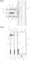
- FIG. 1 to 3 is an embodiment of a T-connection between a post profile 1 and a transom profile 2 running transversely thereto of a post-and-transom construction for facades, conservatories, skylights and the like shown in various representations.
- the two post and transom profiles 1 and 2 are designed in the embodiment shown as hollow profiles with a cavity 3 and identical cross-section. They each have two side walls 4 and 5 parallel to one another and two inner and outer end walls 6 and 7 at right angles to the side walls 4 and 5.
- the outer end wall 7 facing the outside of the post-and-transom construction contains an outwardly projecting web 8 with a receiving channel 9 open to the outside for fastening screws or other fastening elements, through which holding profiles (not shown here) or a holding structure for holding glass panes or other facade elements can be attached to the outer end wall 7.
- the post profile 1 and the transom profile 2 are designed in the form of a metal profile tube, e.g. produced by extrusion, which can be made of steel or aluminum. However, they can also be manufactured as a welded construction from a suitably bent and welded metal sheet, as a wood or plastic construction or the like.
- the outwardly projecting web 8 on the outer front wall 7 facing the outside and used to attach glass panes or other facade elements has, in the embodiment shown, a receiving channel 9 designed as a screw channel. Fastening screws provided with a cutting thread, for example, can be inserted into the receiving channel 9. for fastening retaining profiles or other supporting or facade elements.
- connection between the post profile 1 and the transom profile 2 is made in the Figures 1 to 3 shown embodiment by a connecting element 11 which can be inserted into the cavity 3 of the locking profile 2 at the end thereof and which is designed as a block-shaped plug-in part with an upper and lower side surface 12 and 13 and inner and outer side surfaces 14 and 15 at right angles thereto.
- a locking bolt designed as a locking pin is provided on the connecting element 11.
- Figure 3 recognizable positioning element 16 for engagement in a receiving opening 17 is arranged on the side wall 5 of the post profile 1 facing the locking profile 2.
- a fixed insertion profile 18 is also provided on the side of the connecting element 11 facing the post profile 1 for positive engagement in a transverse groove 19 open towards the outside in the side wall 5 of the post profile 1 facing the locking profile 2.
- the outer contour of the connecting element 11, which is designed as a hollow profile body, is adapted to the inner contour of the cavity 3 of the locking profile 2.
- a holding element 20 designed here as a spring washer, for fastening a guide bolt 21 for the axial guidance of the bolt-shaped positioning element 16, which is prestressed outwards into an engaged position by a compression spring 22.
- the insertion profile 18 which extends along the outer side surface 15 and runs parallel to a longitudinal axis 23 of the connecting element 11 for positive engagement in the transverse groove 19 of the post profile 1.
- the connecting element 11 which is designed here as a profile body made of a hollow profile, is inserted at the end of the transom profile 2 in the direction of the longitudinal axis 24 of the transom profile 2 into the cavity 3 thereof in such a way that the outer side surface 15 of the connecting element 11 is flush with the end surface 25 of the transom profile 2 facing the post profile 1 and the insertion part 18 protrudes relative to the transom profile 2.
- the connecting element 11 is then firmly connected to the locking profile 2 using screws 26, pins or other suitable fastening elements.
- the locking profile 2 has holes 27 arranged in the receiving grooves 10 and the connecting element 11 has screw channels 28 arranged on the outside.
- the insertion profile 18 is designed in the form of a T-slot nut with a T-shaped cross-section.
- the insertion profile 18 is designed as one piece with the connecting element 11 or is molded onto it.
- the insertion profile 18 could also be screwed onto the connecting element 11 or be firmly connected to it in another way.
- the transverse groove 19 running in the post profile 1 transversely to its longitudinal axis is also designed as a T-slot with an inner contour adapted to the outer contour of the insertion profile 18.
- the transverse groove 19 which is open towards the outside of the post profile 1, extends from the outer end wall 7 of the post profile 1 along the side wall 5 of the post profile 1 facing the locking profile 2 in accordance with the length of the insertion profile 18.
- the insertion profile 18 is arranged at the end of the connecting element 11 facing the outer end wall 7, while the positioning element 16 designed as a locking bolt is arranged in the area of the end of the connecting element 11 facing the inner end wall 6 of the locking profile 2. This allows the locking profile 2 to be inserted from the front between two fixed post profiles 1.
- the transverse groove 19 could also be arranged in the inner end wall 6 and the receiving opening 17 in the area of the outer end wall 7 of the post profile 1.
- the inner groove width of the T-shaped transverse groove 19 is adapted to the width of the inner part of the T-shaped insertion profile 18 arranged therein. This allows vertical transverse forces and torsional loads between the locking profile and the post profiles to be transferred.
- the connection between the post and beam profile must be secured by additional screws 30.
- a screw 30 is provided between the inner part of the T-shaped insertion profile 18 and the inner part of the transverse groove 19.
- Figure 2 A recognizable gap 31 is provided into which the screws 30 can be screwed. This allows both bracing in the pulling direction and protection against horizontal transverse forces to be achieved.
- the locking profile 2 which is fitted with two connecting elements 11 at the end, can be inserted horizontally between the post profiles 1 from the front with the positioning elements 16 pressed in, so that the insertion profiles 18 first engage with the transverse grooves 19 and, by further displacement, the positioning elements 16 designed as locking bolts snap into the receiving openings 17.
- the connection can also be tightened using the additional screws 30 or other suitable fastening elements.
Landscapes
- Engineering & Computer Science (AREA)
- Architecture (AREA)
- Physics & Mathematics (AREA)
- Electromagnetism (AREA)
- Civil Engineering (AREA)
- Structural Engineering (AREA)
- Load-Bearing And Curtain Walls (AREA)
Description
- Die Erfindung betrifft eine T-Verbindung zwischen einem Pfosten- und einem Riegelprofil, insbesondere für Pfosten-Riegel-Konstruktionen von Fassaden, Lichtdächern und Wintergärten, nach dem Oberbegriff des Anspruchs 1. Die Erfindung betrifft außerdem eine Pfosten-Riegel-Konstruktion, bei der rechtwinklig zueinander angeordnete Pfosten- und Riegelprofile durch eine T-Verbindung miteinander verbunden sind.
- Eine derartige T-Verbindung ist aus der
DE 299 24 713 U1 bekannt. Dort ist auf ein im Inneren des Riegelprofils verlaufendes Verankerungsprofil ein Verbinder aufgesteckt, der aus einem Formkörper und einem in einer Aufnahme des Formkörpers verschiebbar gelagerten Bundbolzen zum Eingriff in eine Aufnahmeöffnung an einer dem Riegelprofil zugewandten Seitenwand des Pfostenprofils besteht. Der zur ordnungsgemäßen Positionierung dienende Bundbolzen ist innerhalb der Aufnahmeöffnung des Formkörpers gleitend gelagert und wird durch eine Druckfeder in eine nach außen verschobene Montagestellung gedrückt. Damit das Riegelprofil zwischen zwei feststehende Pfostenprofile eingesetzt werden kann, müssen die Bundbolzen von Hand entgegen der Kraft der Druckfeder zurückgedrückt werden und rasten nach der Positionierung an der gewünschten Montagestellung in eine dafür vorgesehene Bohrung an dem Pfostenprofil ein. Zur axialen Sicherung weisen die Bundbolzen versetzte Rastausnehmungen zum formschlüssigen Eingriff in die Bohrung des Pfostenprofils auf. Um jedoch sämtliche Belastungen aufnehmen zu können, ist eine zusätzliche Lastabtragung in Form einer Verschraubung vorgesehen. Hierzu ist das Riegelprofil stirnseitig ausgeklinkt und enthält einen das Pfostenprofil überlappenden Überstand. Durch Bohrungen in dem Überstand und entsprechende Schrauben wird das Riegelprofil mit dem Pfostenprofil verschraubt. Dies ist jedoch mit einem entsprechenden Fertigungs- und Montageaufwand verbunden. Außerdem ist der Bundbolzen nach der Montage von außen nicht mehr zugängig, so dass die Verbindung zwischen dem Pfosten- und Riegelprofil nicht mehr ohne weiteres gelöst werden kann. - Die
EP 0 496 187 A1 und dieDE 198 49 152 A1 offenbaren jeweils den Oberbegriff des Anspruchs 1. - Aufgabe der Erfindung ist es, eine T-Verbindung der eingangs genannten Art und eine Pfosten-Riegel-Konstruktion mit einer solchen T-Verbindung zu schaffen, die eine vereinfachte lasttragende Verbindung von Pfosten- und Riegelprofilen ermöglichen.
- Diese Aufgabe wird durch eine T-Verbindung mit den Merkmalen des Anspruchs 1 und durch eine Pfosten-Riegel-Konstruktion mit den Merkmalen des Anspruchs 11 gelöst. Zweckmäßige Weiterbildungen und vorteilhafte Ausführungsformen der Erfindung sind Gegenstand der Unteransprüche.
- Bei der erfindungsgemäßen T-Verbindung ist die Lastabtrageinrichtung als ein am Verbindungselement fest angeordnetes und sich entlang einer äußeren Seitenfläche des Verbindungselements erstreckendes Einschubprofil zum formschlüssigen Eingriff in eine Quernut des Pfostenprofils ausgebildet. Durch die erfindungsgemäße T-Verbindung kann ein Riegelprofil auch ohne aufwändige Ausklinkungen oder andere zeitintensive Fertigungsmaßnahmen einfach zwischen zwei feststehende Pfostenprofile eingeschoben und gegen sämtliche Belastungen zur Erreichung einer optimalen Lastabtragung gesichert mit einem Pfostenprofil verbunden werden. Die Verbindung kann einfach hergestellt und bei Bedarf auch ohne Beschädigungen wieder gelöst werden.
- In einer besonders zweckmäßigen Ausführung verläuft das Einschubprofil parallel zu einer Längsachse des Verbindungselements. Dadurch kann ein Riegelprofil auf einfache Weise horizontal zwischen zwei vertikale Pfostenprofile eingesetzt und bei Bedarf auch einfach wieder demontiert werden.
- Eine besonders gute Lastabtragung kann z.B. dadurch erreicht werden, dass das Einschubprofil steg- oder leistenförmig ausgebildet ist und einen beispielsweise T-förmigen Querschnitt zum formschlüssigen Eingriff in eine entsprechend T-förmig ausgebildete Quernut des Pfostenprofils aufweist. Dadurch kann das Riegelprofil nicht nur gegen Zugbelastungen, sondern auch gegen Quer- und Torsionsbelastungen gesichert mit dem Pfostenprofil verbunden werden.
- In einer besonders bevorzugten Ausgestaltung ist die Quernut eine zur Außenseite des Pfostenprofils hin offene T-Nut, die sich von der äußeren Stirnwand des Pfostenprofils entsprechend der Länge des Einschubprofils entlang der zum Riegelprofil gewandten Seitenwand des Pfostenprofils erstreckt.
- Das Einschubprofil ist vorzugsweise an dem zu einer äußeren Stirnwand des Riegelprofils gewandten Ende des Verbindungselements angeordnet. Dadurch kann das Riegelprofil von der Vorderseite her zwischen zwei feststehenden Pfostenprofilen eingeschoben werden. Das Einschubprofil kann in einer bevorzugten Ausführung als Profilkörper z.B. aus einem Hohl- oder Vollprofil ausgebildet sein.
- Zur Positionierung und Lagesicherung des Riegelprofils in einer vorgegebenen Montagestellung kann an dem Verbindungselement in einer weiteren vorteilhaften Ausführung ein z.B. als Rastbolzen zum Eingriff in eine Aufnahmeöffnung des Pfostenprofils ausgebildetes Positionierelement angeordnet sein. Das als Rastbolzen ausgebildete Positionierelement kann auf einem Führungsbolzen verschiebbar geführt und durch eine Druckfeder in eine ausgefahrene Einrückstellung beaufschlagt sein.
- Eine erfindungsgemäße Pfosten-Riegel-Konstruktion enthält rechtwinklig miteinander verbundene Pfosten- und Riegelprofile, die durch die vorstehend erläuterte und im Folgenden noch näher beschriebene T-Verbindung miteinander verbunden sind.
- Das Riegelprofil kann fest oder in Richtung seiner Längsachse beweglich mit dem Verbindungselement verbunden sein. Bei einer beweglichen Verbindung können Längenausdehnungen des Riegelprofils ausgeglichen und dennoch ein stabiler Lastabtrag erreicht werden.
- Weitere Besonderheiten und Vorzüge der Erfindung ergeben sich aus der folgenden Beschreibung eines bevorzugten Ausführungsbeispiels anhand der Zeichnung. Es zeigen:
- Figur 1
- ein Ausführungsbeispiel einer T-Verbindung zwischen einem Pfosten- und Riegelprofil mit einem Verbindungselement in einer Explosionsansicht;
- Figur 2
- eine Seitenansicht des Pfosten- und Riegelprofils mit der T-Verbindung von
Figur 1 und - Figur 3
- eine Draufsicht des Pfosten- und Riegelprofils mit der T-Verbindung von
Figur 1 . - In den
Figuren 1 bis 3 ist ein Ausführungsbeispiel einer T-Verbindung zwischen einem Pfostenprofil 1 und einem quer dazu verlaufenden Riegelprofil 2 einer Pfosten-Riegel-Konstruktion für Fassaden, Wintergärten, Lichtdächer und dgl. in verschiedenen Darstellungen gezeigt. Die beiden Pfosten- und Riegelprofile 1 und 2 sind in der gezeigten Ausführung als Hohlprofile mit einem Hohlraum 3 und identischem Querschnitt ausgeführt. Sie weisen jeweils zwei zueinander parallele Seitenwände 4 und 5 und zwei zu den Seitenwänden 4 und 5 rechtwinklige innere und äußere Stirnwände 6 und 7 auf. Die zur Außenseite der Pfosten-Riegel-Konstruktion weisende äußere Stirnwand 7 enthält einen nach außen vorstehenden Steg 8 mit einem zur Außenseite hin offenen Aufnahmekanal 9 für Befestigungsschrauben oder andere Befestigungselemente, durch die hier nicht dargestellte Halteprofile oder eine Haltekonstruktion zur Halterung von Glasscheiben oder anderen Fassadenelementen an der äußeren Stirnwand 7 befestigt werden können. Rechts und links des Stegs 8 sind an der äußeren Stirnwand 7 außerdem in Längsrichtung des Pfosten- bzw. Riegelprofils 1 bzw. 2 verlaufende Aufnahmenuten 10 zur Aufnahme einer Innendichtung oder eines Dichtstücks vorgesehen. - Das Pfostenprofil 1 und das Riegelprofil 2 sind bei der gezeigten Ausführung in Form eines z.B. im Strangpressverfahren hergestellten Metallprofilrohrs ausgeführt, das aus Stahl oder Aluminium bestehen kann. Sie können aber auch als Schweißkonstruktion aus einem entsprechend gebogenen und verschweißten Metallblech, als Holz- bzw. Kunststoffkonstruktion oder dgl. hergestellt sein. Der nach außen vorstehende Steg 8 an der zur Außenseite gerichteten und zur Befestigung von Glasscheiben oder anderer Fassadenelemente dienenden äußeren Stirnwand 7 weist bei dem gezeigten Ausführungsbeispiel einen als Schraubkanal ausgeführten Aufnahmekanal 9 auf. In den Aufnahmekanal 9 können z.B. mit einem Schneidgewinde versehene Befestigungsschrauben zur Befestigung von Halteprofilen oder weiteren Trag- oder Fassadenelementen eingeschraubt werden.
- Die Verbindung zwischen dem Pfostenprofil 1 und dem Riegelprofil 2 erfolgt bei dem in den
Figuren 1 bis 3 gezeigten Ausführungsbeispiel durch ein in den Hohlraum 3 des Riegelprofils 2 an dessen Ende einsteckbares Verbindungselement 11, das als blockförmiges Einsteckteil mit einer oberen und unteren Seitenfläche 12 bzw. 13 und dazu rechtwinkligen inneren und äußeren Seitenflächen 14 bzw. 15 ausgebildet ist. Zur Positionierung und Lagesicherung des Riegelprofils 2 in einer vorgegebenen Montagestellung ist an dem Verbindungselement 11 ein als Rastbolzen ausgebildetes, inFigur 3 erkennbares Positionierelement 16 zum Eingriff in eine Aufnahmeöffnung 17 an der dem Riegelprofil 2 zugewandten Seitenwand 5 des Pfostenprofils 1 angeordnet. Für die Lastabtragung ist an der dem Pfostenprofil 1 zugewandten Seite des Verbindungselements 11 ferner ein feststehendes Einschubprofil 18 zum formschlüssigen Eingriff in eine zur Außenseite hin offene Quernut 19 in der zum Riegelprofil 2 gewandten Seitenwand 5 des Pfostenprofils 1 vorgesehen. - In der gezeigten Ausführung ist die Außenkontur des als Hohlprofilkörper ausgebildeten Verbindungselements 11 an die Innenkontur des Hohlraums 3 des Riegelprofils 2 angepasst. An der dem Riegelprofi 2 zugewandten inneren Seitenfläche 14 des Verbindungselements 11 ist ein hier als Federscheibe ausgebildetes Halteelement 20 zur Befestigung eines Führungsbolzens 21 für die axiale Führung des durch eine Druckfeder 22 nach außen in eine Einrückstellung vorgespannten bolzenförmigen Positionierelements 16 angeordnet. An der dem Pfostenprofil 1 zugewandten äußeren Seitenfläche 15 des Verbindungselements 11 ist das sich entlang der äußeren Seitenfläche 15 erstreckende und parallel zu einer Längsachse 23 des Verbindungselements 11 verlaufende Einschubprofil 18 zum formschlüssigen Eingriff in die Quernut 19 des Pfostenprofils 1 angeordnet.
- Wie aus
Figur 2 hervorgeht, wird das hier als Profilkörper aus einem Hohlprofil ausgebildete Verbindungselement 11 am Ende der Riegelprofils 2 in Richtung der Längsachse 24 des Riegelprofils 2 so in dessen Hohlraum 3 eingesteckt, dass die äußere Seitenfläche 15 des Verbindungselements 11 bündig mit der dem Pfostenprofil 1 zugewandten Stirnfläche 25 des Riegelprofils 2 abschließt und das Einschubteil 18 gegenüber dem Riegelprofil 2 vorsteht. - Anschließend wird das Verbindungselement 11 über Schrauben 26, Stifte oder andere geeignete Befestigungselemente fest mit dem Riegelprofil 2 verbunden. Hierzu weist das Riegelprofil 2 in den Aufnahmenuten 10 angeordnete Bohrungen 27 und das Verbindungselement 11 an der Außenseite angeordnete Schraubkanäle 28 auf.
- Bei der gezeigten Ausführung ist das Einschubprofil 18 in Form eines T-Nutensteins mit einem T-förmigen Querschnitt ausgeführt. Das Einschubprofil 18 ist einstückig mit dem Verbindungselement 11 ausgeführt bzw. an diesem angeformt. Das Einschubprofil 18 könnte aber auch an das Verbindungselement 11 angeschraubt oder auf andere Weise fest mit diesem verbunden sein. Auch die im Pfostenprofil 1 quer zu dessen Längsachse verlaufende Quernut 19 ist als T-Nut mit einer an die Außenkontur des Einschubprofils 18 angepassten Innenkontur ausgeführt.
- Aus der
Figur 1 geht hervor, dass sich die zur Außenseite des Pfostenprofils 1 hin offene Quernut 19 von der äußeren Stirnwand 7 des Pfostenprofils 1 entsprechend der Länge des Einschubprofils 18 entlang der zum Riegelprofil 2 gewandten Seitenwand 5 des Pfostenprofils 1 erstreckt. Die auf der Höhe der Quernut 19 in der Seitenwand 5 angeordnete Aufnahmeöffnung 17 ist dagegen im Bereich der inneren Stirnwand 6 angeordnet, sodass das Riegelprofil 2 im vorderen und hinteren Bereich des Pfostenprofils 1 abgestützt ist. Das Einschubprofil 18 ist an dem zur äußeren Stirnwand 7 gewandten Ende des Verbindungselement 11 angeordnet, während das als Rastbolzen ausgebildete Positionierelement 16 im Bereich des zur inneren Stirnwand 6 des Riegelprofils 2 weisenden Endes des Verbindungselements 11 angeordnet ist. Dadurch kann das Riegelprofil 2 von der Vorderseite her zwischen zwei feststehende Pfostenprofile 1 eingeschoben werden. Bei einer rückseitigen Montage könnte die Quernut 19 auch in der inneren Stirnwand 6 und die Aufnahmeöffnung 17 im Bereich der äußeren Stirnwand 7 des Pfostenprofils 1 angeordnet sein. - In
Figur 2 ist erkennbar, dass die innere Nutbreite der T-förmigen Quernut 19 an die Breite des darin angeordneten inneren Teils des T-förmigen Einschubprofils 18 angepasst ist. Dadurch können vertikale Querkräfte und Torsionsbelastungen zwischen dem Riegelprofil und den Postenprofilen abgetragen werden. Gegen horizontale Querkräfte kann die Verbindung zwischen dem Pfosten- und Riegelprofil durch zusätzliche Schrauben 30 gesichert werden. Hierzu ist zwischen dem inneren Teil des T-förmigen Einschubprofils 18 und dem inneren Teil der Quernut 19 ein inFigur 2 erkennbarer Zwischenraum 31 vorgesehen, in den die Schrauben 30 eingedreht werden können. Dadurch ist sowohl eine Verspannung in Zugrichtung als auch eine Sicherung gegen horizontale Querkräfte erreichbar. - Zur Montage eines Riegelprofils 2 zwischen zwei feststehenden Pfostenprofilen 1 kann das mit zwei Verbindungselementen 11 endseitig bestückte Riegelprofil 2 von der Vorderseite her mit eingedrückten Positionierelementen 16 horizontal zwischen den Pfostenprofilen 1 eingeschoben werden, so dass zunächst die Einschubprofile 18 in Eingriff mit den Quernuten 19 gelangen und durch weitere Verschiebung die als Rastbolzen ausgeführten Positionselemente 16 in die Aufnahmeöffnungen 17 einrasten. Dadurch wird eine sowohl gegen Verdrehung als auch gegen horizontale und vertikale Verschiebung des Riegelprofils gesicherte Verbindung mit einer optimierten Lastabtragung erreicht. Durch die zusätzlichen Schrauben 30 oder andere geeignete Befestigungselemente kann die Verbindung auch noch verspannt werden.
-
- 1
- Pfostenprofil
- 2
- Riegelprofil
- 3
- Hohlraum
- 4
- Seitenwand
- 5
- Seitenwand
- 6
- Innere Stirnwand
- 7
- Äußere Stirnwand
- 8
- Steg
- 9
- Aufnahmekanal
- 10
- Aufnahmenut
- 11
- Verbindungselement
- 12
- Obere Seitenfläche
- 13
- Untere Seitenfläche
- 14
- Innere Seitenfläche
- 15
- Äußere Seitenfläche
- 16
- Positionierelement
- 17
- Aufnahmeöffnung
- 18
- Einschubprofil
- 19
- Quernut
- 20
- Halteelement
- 21
- Führungsbolzen
- 22
- Druckfeder
- 23
- Längsachse des Verbindungselements
- 24
- Längsachse des Riegelprofils
- 25
- Stirnfläche des Riegelprofils
- 26
- Schraube
- 27
- Bohrung
- 28
- Schraubkanal
- 29
- Längsachse des Pfostenprofils
- 30
- Schraube
- 31
- Zwischenraum
Claims (15)
- T-Verbindung zwischen einem Pfostenprofil (1) und einem Riegelprofil (2), insbesondere für Pfosten-Riegel-Konstruktionen von Fassaden, Lichtdächern und Wintergärten, mit mindestens einem in einen Hohlraum (3) des Riegelprofils (2) einsetzbaren Verbindungselement (11) und einer Lastabtrageinrichtung zur lasttragenden Verbindung des Riegelprofils (2) mit dem Pfostenprofil (1), wobei die Lastabtrageinrichtung als ein am Verbindungselement (11) fest angeordnetes und sich entlang einer äußeren Seitenfläche (15) des Verbindungselements (11) erstreckendes Einschubprofil (18) ausgebildet ist, gekennzeichnet durch einen formschlüssigen Eingriff des Einschubprofils (18) in eine Quernut (19) des Pfostenprofils (1).
- T-Verbindung nach Anspruch 1, dadurch gekennzeichnet, dass das Einschubprofil (18) parallel zu einer Längsachse (23) des Verbindungselements (11) verläuft.
- T-Verbindung nach Anspruch 1 oder 2, dadurch gekennzeichnet, dass das Einschubprofil (18) steg- bzw. leistenförmig, insbesondere als Einschubprofil (18) mit einem T-förmigen Querschnitt, ausgebildet ist.
- T-Verbindung nach einem der Ansprüche 1 bis 3, dadurch gekennzeichnet, dass die Quernut (19) eine zur Außenseite des Pfostenprofils (1) hin offene T-Nut ist, die sich von der äußeren Stirnwand (7) des Pfostenprofils (1) entsprechend der Länge des Einschubprofils (18) entlang der zum Riegelprofil (2) gewandten Seitenwand (5) des Pfostenprofils (1) erstreckt.
- T-Verbindung nach einem der Ansprüche 1 bis 4, dadurch gekennzeichnet, dass das Einschubprofil (18) an dem zu einer äußeren Stirnwand (7) des Riegelprofils (2) gewandten Ende des Verbindungselements (11) angeordnet ist.
- T-Verbindung nach einem der Ansprüche 1 bis 5, dadurch gekennzeichnet, dass an dem Verbindungselement (11) ein Positionierelement (16) zur Lagesicherung des Riegelprofils (2) in einer vorgegebenen Montagestellung angeordnet ist.
- T-Verbindung nach Anspruch 6, dadurch gekennzeichnet, dass das Positionierelement (16) als ein in eine Aufnahmeöffnung (17) des Pfostenprofils (1) eingreifender Rastbolzen ausgebildet ist.
- T-Verbindung nach Anspruch 6 oder 7, dadurch gekennzeichnet, dass das Positionierelement (16) auf einem Führungsbolzen (21) verschiebbar geführt und durch eine Druckfeder (22) in eine ausgefahrene Einrückstellung beaufschlagt ist.
- T-Verbindung nach einem der Ansprüche 1 bis 8, dadurch gekennzeichnet, dass das Verbindungselement (11) als Profilkörper mit einer an die Innenkontur des Riegelprofils (2) angepassten Außenkontur ausgebildet ist und/oder dass das Verbindungselement (11) als blockförmiges Einsteckteil mit oberen und unteren Seitenflächen (12, 13) sowie inneren und äußeren Seitenflächen (14, 15) ausgebildet ist.
- T-Verbindung nach einem der Ansprüche 1 bis 9, dadurch gekennzeichnet, dass an der Außenseite des Verbindungselements (11) mehrere Schraubkanäle (28) zur Befestigung des Verbindungselements (11) in dem Riegelprofil (2) vorgesehen sind.
- Pfosten/Riegel-Konstruktion, insbesondere für Fassaden und Wintergärten, die rechtwinklig miteinander verbundene Pfostenprofile (1) und Riegelprofile (2) enthält, dadurch gekennzeichnet, dass die Pfostenprofile (1) und die Riegelprofile (2) durch eine T-Verbindung nach einem der Ansprüche 1 bis 10 miteinander verbunden sind.
- Pfosten/Riegel-Konstruktion nach Anspruch 11, dadurch gekennzeichnet, dass die Pfostenprofile (1) eine quer zu deren Längsachsen (29) verlaufende Quernut (19) zur Aufnahme des Einschubprofils (18) am Verbindungelement (11) aufweisen.
- Pfosten/Riegel-Konstruktion nach Anspruch 12, dadurch gekennzeichnet, dass sich die Quernut (19) von einer äußeren Stirnwand (7) des Pfostenprofils (1) entsprechend der Länge des Einschubprofils entlang einer dem Riegelprofil (2) zugewandten Seitenwand (5) des Pfostenprofils (1) erstreckt.
- Pfosten/Riegel-Konstruktion nach einem der Ansprüche 11 bis 13, dadurch gekennzeichnet, dass die Quernut (19) als T-Nut ausgebildet ist.
- Pfosten/Riegel-Konstruktion nach einem der Ansprüche 12 bis 14, dadurch gekennzeichnet, dass das Riegelprofil (2) fest oder in Richtung seiner Längsachse (24) beweglich mit dem Verbindungselement (11) verbunden ist.
Applications Claiming Priority (1)
| Application Number | Priority Date | Filing Date | Title |
|---|---|---|---|
| DE102020106891.3A DE102020106891B4 (de) | 2020-03-13 | 2020-03-13 | T-Verbindung zwischen einem Pfosten- und Riegelprofil und Pfosten-Riegel-Konstruktion mit einer derartigen T-Verbindung |
Publications (2)
| Publication Number | Publication Date |
|---|---|
| EP3879042A1 EP3879042A1 (de) | 2021-09-15 |
| EP3879042B1 true EP3879042B1 (de) | 2024-07-24 |
Family
ID=74758668
Family Applications (1)
| Application Number | Title | Priority Date | Filing Date |
|---|---|---|---|
| EP21159331.4A Active EP3879042B1 (de) | 2020-03-13 | 2021-02-25 | T-verbindung zwischen einem pfosten- und riegelprofil und pfosten-riegel-konstruktion mit einer derartigen t-verbindung |
Country Status (2)
| Country | Link |
|---|---|
| EP (1) | EP3879042B1 (de) |
| DE (1) | DE102020106891B4 (de) |
Family Cites Families (8)
| Publication number | Priority date | Publication date | Assignee | Title |
|---|---|---|---|---|
| AT231663B (de) | 1958-06-05 | 1964-02-10 | Walter Ciro Cavecchi | Verbindung von aus Pfosten und Querstäben bestehenden Bauelementen zur Bildung eines Fachwerkes |
| ATE76922T1 (de) | 1989-03-02 | 1992-06-15 | Gerhard Mische | Bausatz fuer ein bauwerk. |
| IT1245101B (it) * | 1991-01-23 | 1994-09-13 | Metra Metall Trafilati Allumin | Serie di profilati cooperanti, per la realizzazione di pareti vetrate continue di edifici |
| DE19849152C5 (de) * | 1998-10-26 | 2013-10-10 | Gutmann Ag | Pfosten-Riegelverbindung |
| DE29924713U1 (de) | 1999-01-18 | 2005-01-27 | SCHÜCO International KG | T-Verbindung zwischen einem Sprossen- und einem Pfostenprofil einer Fassade oder eines Lichtdaches |
| IES20060089A2 (en) * | 2006-02-10 | 2006-11-15 | Apa Systems Ltd | A curtain walling system |
| EP2322732B1 (de) | 2009-11-16 | 2012-06-20 | W.M.K.Secur S.r.l. | Fassade oder Glaswand in Brandschutzausführung |
| DE202012101289U1 (de) | 2012-04-11 | 2013-07-12 | SCHÜCO International KG | T-Verbindung und Pfosten-Riegel-Konstruktion |
-
2020
- 2020-03-13 DE DE102020106891.3A patent/DE102020106891B4/de active Active
-
2021
- 2021-02-25 EP EP21159331.4A patent/EP3879042B1/de active Active
Also Published As
| Publication number | Publication date |
|---|---|
| DE102020106891B4 (de) | 2021-09-30 |
| EP3879042A1 (de) | 2021-09-15 |
| DE102020106891A1 (de) | 2021-09-16 |
Similar Documents
| Publication | Publication Date | Title |
|---|---|---|
| EP0476289B1 (de) | Fassadenkonstruktion aus einer Tragkonstruktion mit davorgesetzter Fassadenprofilkonstruktion | |
| EP3529430B1 (de) | Pfosten für eine pfosten-riegel-konstruktion | |
| DE19849152A1 (de) | Pfosten-Riegelverbindung | |
| EP3130717B1 (de) | Pfosten-riegel-verbindung | |
| EP3205532B1 (de) | Drehvorrichtung für einen fahrzeugsitz | |
| EP4102022B1 (de) | Fenster- oder tür-hohlkammerprofil, system mit einem solchen hohlkammerprofil und daraus hergestellter rahmen | |
| EP1098046B1 (de) | Verkleidungssystem für Fassaden und Dächer von Bauwerken | |
| EP4012132B1 (de) | T-verbindung für pfosten-riegel-konstruktionen und pfosten-riegel-konstruktion mit einer derartigen t-verbindung | |
| DE102015220086B4 (de) | Montageanordnung zur Befestigung von Bauelementen in einer Maueröffnung sowie Lastaufnahmeteil hierfür | |
| DE3603221C2 (de) | ||
| EP2186959B1 (de) | T-Verbindung zwischen einem Pfosten- und Riegelprofil | |
| DE102020106891B4 (de) | T-Verbindung zwischen einem Pfosten- und Riegelprofil und Pfosten-Riegel-Konstruktion mit einer derartigen T-Verbindung | |
| EP0955420A2 (de) | Fassadenprofil | |
| EP4102019B1 (de) | Fenster- oder tür-hohlkammerprofil, system mit einem solchen hohlkammerprofil und daraus hergestellter rahmen | |
| EP1602836B1 (de) | Gratleiste für Massivholz | |
| DE29501568U1 (de) | Verbindungselement | |
| DE102006004493B4 (de) | Führungsschienenbefestigung | |
| DE10229272A1 (de) | Stoßverbinder zum winkeligen Verbinden von Hohlprofilen | |
| DE102024100923A1 (de) | Kopplungsvorrichtung für Gebäudefassaden oder -fenster | |
| DE10043444B4 (de) | Fenster- oder Türrahmen mit einem verschraubten Verbinder | |
| DE19943310C2 (de) | Rechteckiges Hohlkammerprofil sowie daraus bildbares Tragwerk | |
| DE20203512U1 (de) | Rahmensystemanordnung | |
| DD296135A5 (de) | Verbindungstraeger zur befestigung von rahmenkonstruktionen | |
| EP1329571A2 (de) | Gerüstkupplung | |
| EP4086404A1 (de) | Gebäudeverschlussanordnung zur anordnung an einer gebäudehülle eines gebäudes sowie entsprechendes gebäude |
Legal Events
| Date | Code | Title | Description |
|---|---|---|---|
| PUAI | Public reference made under article 153(3) epc to a published international application that has entered the european phase |
Free format text: ORIGINAL CODE: 0009012 |
|
| STAA | Information on the status of an ep patent application or granted ep patent |
Free format text: STATUS: THE APPLICATION HAS BEEN PUBLISHED |
|
| AK | Designated contracting states |
Kind code of ref document: A1 Designated state(s): AL AT BE BG CH CY CZ DE DK EE ES FI FR GB GR HR HU IE IS IT LI LT LU LV MC MK MT NL NO PL PT RO RS SE SI SK SM TR |
|
| STAA | Information on the status of an ep patent application or granted ep patent |
Free format text: STATUS: REQUEST FOR EXAMINATION WAS MADE |
|
| 17P | Request for examination filed |
Effective date: 20220315 |
|
| RBV | Designated contracting states (corrected) |
Designated state(s): AL AT BE BG CH CY CZ DE DK EE ES FI FR GB GR HR HU IE IS IT LI LT LU LV MC MK MT NL NO PL PT RO RS SE SI SK SM TR |
|
| GRAP | Despatch of communication of intention to grant a patent |
Free format text: ORIGINAL CODE: EPIDOSNIGR1 |
|
| STAA | Information on the status of an ep patent application or granted ep patent |
Free format text: STATUS: GRANT OF PATENT IS INTENDED |
|
| RIC1 | Information provided on ipc code assigned before grant |
Ipc: E04B 2/96 20060101AFI20240223BHEP |
|
| INTG | Intention to grant announced |
Effective date: 20240312 |
|
| GRAS | Grant fee paid |
Free format text: ORIGINAL CODE: EPIDOSNIGR3 |
|
| GRAA | (expected) grant |
Free format text: ORIGINAL CODE: 0009210 |
|
| STAA | Information on the status of an ep patent application or granted ep patent |
Free format text: STATUS: THE PATENT HAS BEEN GRANTED |
|
| AK | Designated contracting states |
Kind code of ref document: B1 Designated state(s): AL AT BE BG CH CY CZ DE DK EE ES FI FR GB GR HR HU IE IS IT LI LT LU LV MC MK MT NL NO PL PT RO RS SE SI SK SM TR |
|
| REG | Reference to a national code |
Ref country code: GB Ref legal event code: FG4D Free format text: NOT ENGLISH |
|
| REG | Reference to a national code |
Ref country code: CH Ref legal event code: EP |
|
| REG | Reference to a national code |
Ref country code: DE Ref legal event code: R096 Ref document number: 502021004452 Country of ref document: DE |
|
| P01 | Opt-out of the competence of the unified patent court (upc) registered |
Free format text: CASE NUMBER: APP_40547/2024 Effective date: 20240709 |
|
| REG | Reference to a national code |
Ref country code: IE Ref legal event code: FG4D Free format text: LANGUAGE OF EP DOCUMENT: GERMAN |
|
| REG | Reference to a national code |
Ref country code: LT Ref legal event code: MG9D |
|
| REG | Reference to a national code |
Ref country code: NL Ref legal event code: MP Effective date: 20240724 |
|
| PG25 | Lapsed in a contracting state [announced via postgrant information from national office to epo] |
Ref country code: PT Free format text: LAPSE BECAUSE OF FAILURE TO SUBMIT A TRANSLATION OF THE DESCRIPTION OR TO PAY THE FEE WITHIN THE PRESCRIBED TIME-LIMIT Effective date: 20241125 |
|
| PG25 | Lapsed in a contracting state [announced via postgrant information from national office to epo] |
Ref country code: NL Free format text: LAPSE BECAUSE OF FAILURE TO SUBMIT A TRANSLATION OF THE DESCRIPTION OR TO PAY THE FEE WITHIN THE PRESCRIBED TIME-LIMIT Effective date: 20240724 |
|
| PG25 | Lapsed in a contracting state [announced via postgrant information from national office to epo] |
Ref country code: PT Free format text: LAPSE BECAUSE OF FAILURE TO SUBMIT A TRANSLATION OF THE DESCRIPTION OR TO PAY THE FEE WITHIN THE PRESCRIBED TIME-LIMIT Effective date: 20241125 Ref country code: NL Free format text: LAPSE BECAUSE OF FAILURE TO SUBMIT A TRANSLATION OF THE DESCRIPTION OR TO PAY THE FEE WITHIN THE PRESCRIBED TIME-LIMIT Effective date: 20240724 |
|
| PG25 | Lapsed in a contracting state [announced via postgrant information from national office to epo] |
Ref country code: NO Free format text: LAPSE BECAUSE OF FAILURE TO SUBMIT A TRANSLATION OF THE DESCRIPTION OR TO PAY THE FEE WITHIN THE PRESCRIBED TIME-LIMIT Effective date: 20241024 |
|
| PG25 | Lapsed in a contracting state [announced via postgrant information from national office to epo] |
Ref country code: FI Free format text: LAPSE BECAUSE OF FAILURE TO SUBMIT A TRANSLATION OF THE DESCRIPTION OR TO PAY THE FEE WITHIN THE PRESCRIBED TIME-LIMIT Effective date: 20240724 Ref country code: GR Free format text: LAPSE BECAUSE OF FAILURE TO SUBMIT A TRANSLATION OF THE DESCRIPTION OR TO PAY THE FEE WITHIN THE PRESCRIBED TIME-LIMIT Effective date: 20241025 Ref country code: PL Free format text: LAPSE BECAUSE OF FAILURE TO SUBMIT A TRANSLATION OF THE DESCRIPTION OR TO PAY THE FEE WITHIN THE PRESCRIBED TIME-LIMIT Effective date: 20240724 |
|
| PG25 | Lapsed in a contracting state [announced via postgrant information from national office to epo] |
Ref country code: BG Free format text: LAPSE BECAUSE OF FAILURE TO SUBMIT A TRANSLATION OF THE DESCRIPTION OR TO PAY THE FEE WITHIN THE PRESCRIBED TIME-LIMIT Effective date: 20240724 |
|
| PG25 | Lapsed in a contracting state [announced via postgrant information from national office to epo] |
Ref country code: LV Free format text: LAPSE BECAUSE OF FAILURE TO SUBMIT A TRANSLATION OF THE DESCRIPTION OR TO PAY THE FEE WITHIN THE PRESCRIBED TIME-LIMIT Effective date: 20240724 |
|
| PG25 | Lapsed in a contracting state [announced via postgrant information from national office to epo] |
Ref country code: IS Free format text: LAPSE BECAUSE OF FAILURE TO SUBMIT A TRANSLATION OF THE DESCRIPTION OR TO PAY THE FEE WITHIN THE PRESCRIBED TIME-LIMIT Effective date: 20241124 |
|
| PG25 | Lapsed in a contracting state [announced via postgrant information from national office to epo] |
Ref country code: HR Free format text: LAPSE BECAUSE OF FAILURE TO SUBMIT A TRANSLATION OF THE DESCRIPTION OR TO PAY THE FEE WITHIN THE PRESCRIBED TIME-LIMIT Effective date: 20240724 |
|
| PG25 | Lapsed in a contracting state [announced via postgrant information from national office to epo] |
Ref country code: RS Free format text: LAPSE BECAUSE OF FAILURE TO SUBMIT A TRANSLATION OF THE DESCRIPTION OR TO PAY THE FEE WITHIN THE PRESCRIBED TIME-LIMIT Effective date: 20241024 Ref country code: ES Free format text: LAPSE BECAUSE OF FAILURE TO SUBMIT A TRANSLATION OF THE DESCRIPTION OR TO PAY THE FEE WITHIN THE PRESCRIBED TIME-LIMIT Effective date: 20240724 |
|
| PG25 | Lapsed in a contracting state [announced via postgrant information from national office to epo] |
Ref country code: RS Free format text: LAPSE BECAUSE OF FAILURE TO SUBMIT A TRANSLATION OF THE DESCRIPTION OR TO PAY THE FEE WITHIN THE PRESCRIBED TIME-LIMIT Effective date: 20241024 Ref country code: PL Free format text: LAPSE BECAUSE OF FAILURE TO SUBMIT A TRANSLATION OF THE DESCRIPTION OR TO PAY THE FEE WITHIN THE PRESCRIBED TIME-LIMIT Effective date: 20240724 Ref country code: NO Free format text: LAPSE BECAUSE OF FAILURE TO SUBMIT A TRANSLATION OF THE DESCRIPTION OR TO PAY THE FEE WITHIN THE PRESCRIBED TIME-LIMIT Effective date: 20241024 Ref country code: LV Free format text: LAPSE BECAUSE OF FAILURE TO SUBMIT A TRANSLATION OF THE DESCRIPTION OR TO PAY THE FEE WITHIN THE PRESCRIBED TIME-LIMIT Effective date: 20240724 Ref country code: IS Free format text: LAPSE BECAUSE OF FAILURE TO SUBMIT A TRANSLATION OF THE DESCRIPTION OR TO PAY THE FEE WITHIN THE PRESCRIBED TIME-LIMIT Effective date: 20241124 Ref country code: HR Free format text: LAPSE BECAUSE OF FAILURE TO SUBMIT A TRANSLATION OF THE DESCRIPTION OR TO PAY THE FEE WITHIN THE PRESCRIBED TIME-LIMIT Effective date: 20240724 Ref country code: GR Free format text: LAPSE BECAUSE OF FAILURE TO SUBMIT A TRANSLATION OF THE DESCRIPTION OR TO PAY THE FEE WITHIN THE PRESCRIBED TIME-LIMIT Effective date: 20241025 Ref country code: FI Free format text: LAPSE BECAUSE OF FAILURE TO SUBMIT A TRANSLATION OF THE DESCRIPTION OR TO PAY THE FEE WITHIN THE PRESCRIBED TIME-LIMIT Effective date: 20240724 Ref country code: ES Free format text: LAPSE BECAUSE OF FAILURE TO SUBMIT A TRANSLATION OF THE DESCRIPTION OR TO PAY THE FEE WITHIN THE PRESCRIBED TIME-LIMIT Effective date: 20240724 Ref country code: BG Free format text: LAPSE BECAUSE OF FAILURE TO SUBMIT A TRANSLATION OF THE DESCRIPTION OR TO PAY THE FEE WITHIN THE PRESCRIBED TIME-LIMIT Effective date: 20240724 |
|
| PG25 | Lapsed in a contracting state [announced via postgrant information from national office to epo] |
Ref country code: SM Free format text: LAPSE BECAUSE OF FAILURE TO SUBMIT A TRANSLATION OF THE DESCRIPTION OR TO PAY THE FEE WITHIN THE PRESCRIBED TIME-LIMIT Effective date: 20240724 Ref country code: RO Free format text: LAPSE BECAUSE OF FAILURE TO SUBMIT A TRANSLATION OF THE DESCRIPTION OR TO PAY THE FEE WITHIN THE PRESCRIBED TIME-LIMIT Effective date: 20240724 Ref country code: DK Free format text: LAPSE BECAUSE OF FAILURE TO SUBMIT A TRANSLATION OF THE DESCRIPTION OR TO PAY THE FEE WITHIN THE PRESCRIBED TIME-LIMIT Effective date: 20240724 |
|
| PG25 | Lapsed in a contracting state [announced via postgrant information from national office to epo] |
Ref country code: EE Free format text: LAPSE BECAUSE OF FAILURE TO SUBMIT A TRANSLATION OF THE DESCRIPTION OR TO PAY THE FEE WITHIN THE PRESCRIBED TIME-LIMIT Effective date: 20240724 |
|
| PG25 | Lapsed in a contracting state [announced via postgrant information from national office to epo] |
Ref country code: CZ Free format text: LAPSE BECAUSE OF FAILURE TO SUBMIT A TRANSLATION OF THE DESCRIPTION OR TO PAY THE FEE WITHIN THE PRESCRIBED TIME-LIMIT Effective date: 20240724 |
|
| REG | Reference to a national code |
Ref country code: DE Ref legal event code: R097 Ref document number: 502021004452 Country of ref document: DE |
|
| PG25 | Lapsed in a contracting state [announced via postgrant information from national office to epo] |
Ref country code: IT Free format text: LAPSE BECAUSE OF FAILURE TO SUBMIT A TRANSLATION OF THE DESCRIPTION OR TO PAY THE FEE WITHIN THE PRESCRIBED TIME-LIMIT Effective date: 20240724 Ref country code: SK Free format text: LAPSE BECAUSE OF FAILURE TO SUBMIT A TRANSLATION OF THE DESCRIPTION OR TO PAY THE FEE WITHIN THE PRESCRIBED TIME-LIMIT Effective date: 20240724 |
|
| PLBE | No opposition filed within time limit |
Free format text: ORIGINAL CODE: 0009261 |
|
| STAA | Information on the status of an ep patent application or granted ep patent |
Free format text: STATUS: NO OPPOSITION FILED WITHIN TIME LIMIT |
|
| 26N | No opposition filed |
Effective date: 20250425 |
|
| PG25 | Lapsed in a contracting state [announced via postgrant information from national office to epo] |
Ref country code: SE Free format text: LAPSE BECAUSE OF FAILURE TO SUBMIT A TRANSLATION OF THE DESCRIPTION OR TO PAY THE FEE WITHIN THE PRESCRIBED TIME-LIMIT Effective date: 20240724 |
|
| PG25 | Lapsed in a contracting state [announced via postgrant information from national office to epo] |
Ref country code: MC Free format text: LAPSE BECAUSE OF FAILURE TO SUBMIT A TRANSLATION OF THE DESCRIPTION OR TO PAY THE FEE WITHIN THE PRESCRIBED TIME-LIMIT Effective date: 20240724 |
|
| PG25 | Lapsed in a contracting state [announced via postgrant information from national office to epo] |
Ref country code: LU Free format text: LAPSE BECAUSE OF NON-PAYMENT OF DUE FEES Effective date: 20250225 |
|
| REG | Reference to a national code |
Ref country code: BE Ref legal event code: MM Effective date: 20250228 |
|
| PG25 | Lapsed in a contracting state [announced via postgrant information from national office to epo] |
Ref country code: BE Free format text: LAPSE BECAUSE OF NON-PAYMENT OF DUE FEES Effective date: 20250228 |
|
| PG25 | Lapsed in a contracting state [announced via postgrant information from national office to epo] |
Ref country code: IE Free format text: LAPSE BECAUSE OF NON-PAYMENT OF DUE FEES Effective date: 20250225 |
|
| REG | Reference to a national code |
Ref country code: CH Ref legal event code: U11 Free format text: ST27 STATUS EVENT CODE: U-0-0-U10-U11 (AS PROVIDED BY THE NATIONAL OFFICE) Effective date: 20260301 |
|
| PGFP | Annual fee paid to national office [announced via postgrant information from national office to epo] |
Ref country code: GB Payment date: 20260219 Year of fee payment: 6 |
|
| PGFP | Annual fee paid to national office [announced via postgrant information from national office to epo] |
Ref country code: DE Payment date: 20260306 Year of fee payment: 6 |
|
| PGFP | Annual fee paid to national office [announced via postgrant information from national office to epo] |
Ref country code: AT Payment date: 20260216 Year of fee payment: 6 |
|
| PGFP | Annual fee paid to national office [announced via postgrant information from national office to epo] |
Ref country code: FR Payment date: 20260219 Year of fee payment: 6 |
|
| PGFP | Annual fee paid to national office [announced via postgrant information from national office to epo] |
Ref country code: CH Payment date: 20260301 Year of fee payment: 6 |