EP3879042B1 - Raccord en t entre un profilé de montants et de traverses et construction de montants et de traverses dotée d'un tel raccord en t - Google Patents
Raccord en t entre un profilé de montants et de traverses et construction de montants et de traverses dotée d'un tel raccord en t Download PDFInfo
- Publication number
- EP3879042B1 EP3879042B1 EP21159331.4A EP21159331A EP3879042B1 EP 3879042 B1 EP3879042 B1 EP 3879042B1 EP 21159331 A EP21159331 A EP 21159331A EP 3879042 B1 EP3879042 B1 EP 3879042B1
- Authority
- EP
- European Patent Office
- Prior art keywords
- profile
- transom
- mullion
- connecting element
- connection
- Prior art date
- Legal status (The legal status is an assumption and is not a legal conclusion. Google has not performed a legal analysis and makes no representation as to the accuracy of the status listed.)
- Active
Links
Images

Classifications
-
- E—FIXED CONSTRUCTIONS
- E04—BUILDING
- E04B—GENERAL BUILDING CONSTRUCTIONS; WALLS, e.g. PARTITIONS; ROOFS; FLOORS; CEILINGS; INSULATION OR OTHER PROTECTION OF BUILDINGS
- E04B2/00—Walls, e.g. partitions, for buildings; Wall construction with regard to insulation; Connections specially adapted to walls
- E04B2/88—Curtain walls
- E04B2/96—Curtain walls comprising panels attached to the structure through mullions or transoms
- E04B2/965—Connections of mullions and transoms
Definitions
- the invention relates to a T-connection between a mullion and a transom profile, in particular for mullion-transom constructions of facades, skylights and winter gardens, according to the preamble of claim 1.
- the invention also relates to a mullion-transom construction in which mullion and transom profiles arranged at right angles to one another are connected to one another by a T-connection.
- Such a T-connection is from the DE 299 24 713 U1 known.
- a connector is attached to an anchoring profile running inside the transom profile, which consists of a shaped body and a collar bolt that is slidably mounted in a holder of the shaped body for engagement in a receiving opening on a side wall of the post profile facing the transom profile.
- the collar bolt which is used for correct positioning, is slidably mounted within the receiving opening of the shaped body and is pressed into an outwardly displaced assembly position by a compression spring.
- the collar bolts In order for the transom profile to be inserted between two fixed post profiles, the collar bolts must be pressed back by hand against the force of the compression spring and, after positioning in the desired assembly position, they engage in a hole provided for this purpose on the post profile. For axial securing, the collar bolts have offset locking recesses for positive engagement in the hole of the post profile. However, in order to be able to absorb all loads, an additional load transfer in the form of a screw connection is provided. For this purpose, the transom profile is notched at the front and contains a projection that overlaps the post profile. The transom profile is screwed to the post profile using holes in the projection and corresponding screws. However, this involves a corresponding amount of manufacturing and assembly work. In addition, the collar bolt is no longer accessible from the outside after assembly, so that the connection between the post and transom profile can no longer be easily removed.
- the object of the invention is to provide a T-connection of the type mentioned at the outset and a mullion-transom construction with such a T-connection, which enable a simplified load-bearing connection of mullion and transom profiles.
- the load transfer device is designed as an insertion profile that is fixedly arranged on the connecting element and extends along an outer side surface of the connecting element for positive engagement in a transverse groove of the post profile.
- the T-connection according to the invention allows a transom profile to be easily inserted between two fixed post profiles without complex notches or other time-consuming manufacturing measures and connected to a post profile in a way that is secured against all loads in order to achieve optimal load transfer.
- the connection can be easily made and, if necessary, released again without damage.
- the insertion profile runs parallel to a longitudinal axis of the connecting element. This means that a transom profile can be easily inserted horizontally between two vertical post profiles and can also be easily removed again if necessary.
- a particularly good load transfer can be achieved, for example, if the insertion profile is designed in the form of a web or strip and has, for example, a T-shaped cross section for positive engagement in a correspondingly T-shaped transverse groove in the post profile.
- the transom profile can be connected to the post profile in a way that is not only protected against tensile loads, but also against transverse and torsional loads.
- the transverse groove is a T-groove that is open towards the outside of the post profile and extends from the outer end wall of the post profile according to the length of the insertion profile along the side wall of the post profile facing the transom profile.
- the insertion profile is preferably arranged at the end of the connecting element facing an outer end wall of the locking profile. This allows the locking profile to be inserted from the front between two fixed post profiles.
- the insertion profile can be designed as a profile body, e.g. from a hollow or solid profile.
- a positioning element designed, for example, as a locking bolt for engaging in a receiving opening in the post profile can be arranged on the connecting element in a further advantageous embodiment.
- the positioning element designed as a locking bolt can be slidably guided on a guide bolt and can be pushed into an extended, engaged position by a compression spring.
- a mullion-transom construction according to the invention contains mullion and transom profiles connected at right angles to one another, which are connected to one another by the T-connection explained above and described in more detail below.
- the transom profile can be connected to the connecting element either firmly or so that it can move along its longitudinal axis. With a movable connection, longitudinal expansion of the transom profile can be compensated for and stable load transfer can still be achieved.
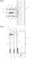
- FIG. 1 to 3 is an embodiment of a T-connection between a post profile 1 and a transom profile 2 running transversely thereto of a post-and-transom construction for facades, conservatories, skylights and the like shown in various representations.
- the two post and transom profiles 1 and 2 are designed in the embodiment shown as hollow profiles with a cavity 3 and identical cross-section. They each have two side walls 4 and 5 parallel to one another and two inner and outer end walls 6 and 7 at right angles to the side walls 4 and 5.
- the outer end wall 7 facing the outside of the post-and-transom construction contains an outwardly projecting web 8 with a receiving channel 9 open to the outside for fastening screws or other fastening elements, through which holding profiles (not shown here) or a holding structure for holding glass panes or other facade elements can be attached to the outer end wall 7.
- the post profile 1 and the transom profile 2 are designed in the form of a metal profile tube, e.g. produced by extrusion, which can be made of steel or aluminum. However, they can also be manufactured as a welded construction from a suitably bent and welded metal sheet, as a wood or plastic construction or the like.
- the outwardly projecting web 8 on the outer front wall 7 facing the outside and used to attach glass panes or other facade elements has, in the embodiment shown, a receiving channel 9 designed as a screw channel. Fastening screws provided with a cutting thread, for example, can be inserted into the receiving channel 9. for fastening retaining profiles or other supporting or facade elements.
- connection between the post profile 1 and the transom profile 2 is made in the Figures 1 to 3 shown embodiment by a connecting element 11 which can be inserted into the cavity 3 of the locking profile 2 at the end thereof and which is designed as a block-shaped plug-in part with an upper and lower side surface 12 and 13 and inner and outer side surfaces 14 and 15 at right angles thereto.
- a locking bolt designed as a locking pin is provided on the connecting element 11.
- Figure 3 recognizable positioning element 16 for engagement in a receiving opening 17 is arranged on the side wall 5 of the post profile 1 facing the locking profile 2.
- a fixed insertion profile 18 is also provided on the side of the connecting element 11 facing the post profile 1 for positive engagement in a transverse groove 19 open towards the outside in the side wall 5 of the post profile 1 facing the locking profile 2.
- the outer contour of the connecting element 11, which is designed as a hollow profile body, is adapted to the inner contour of the cavity 3 of the locking profile 2.
- a holding element 20 designed here as a spring washer, for fastening a guide bolt 21 for the axial guidance of the bolt-shaped positioning element 16, which is prestressed outwards into an engaged position by a compression spring 22.
- the insertion profile 18 which extends along the outer side surface 15 and runs parallel to a longitudinal axis 23 of the connecting element 11 for positive engagement in the transverse groove 19 of the post profile 1.
- the connecting element 11 which is designed here as a profile body made of a hollow profile, is inserted at the end of the transom profile 2 in the direction of the longitudinal axis 24 of the transom profile 2 into the cavity 3 thereof in such a way that the outer side surface 15 of the connecting element 11 is flush with the end surface 25 of the transom profile 2 facing the post profile 1 and the insertion part 18 protrudes relative to the transom profile 2.
- the connecting element 11 is then firmly connected to the locking profile 2 using screws 26, pins or other suitable fastening elements.
- the locking profile 2 has holes 27 arranged in the receiving grooves 10 and the connecting element 11 has screw channels 28 arranged on the outside.
- the insertion profile 18 is designed in the form of a T-slot nut with a T-shaped cross-section.
- the insertion profile 18 is designed as one piece with the connecting element 11 or is molded onto it.
- the insertion profile 18 could also be screwed onto the connecting element 11 or be firmly connected to it in another way.
- the transverse groove 19 running in the post profile 1 transversely to its longitudinal axis is also designed as a T-slot with an inner contour adapted to the outer contour of the insertion profile 18.
- the transverse groove 19 which is open towards the outside of the post profile 1, extends from the outer end wall 7 of the post profile 1 along the side wall 5 of the post profile 1 facing the locking profile 2 in accordance with the length of the insertion profile 18.
- the insertion profile 18 is arranged at the end of the connecting element 11 facing the outer end wall 7, while the positioning element 16 designed as a locking bolt is arranged in the area of the end of the connecting element 11 facing the inner end wall 6 of the locking profile 2. This allows the locking profile 2 to be inserted from the front between two fixed post profiles 1.
- the transverse groove 19 could also be arranged in the inner end wall 6 and the receiving opening 17 in the area of the outer end wall 7 of the post profile 1.
- the inner groove width of the T-shaped transverse groove 19 is adapted to the width of the inner part of the T-shaped insertion profile 18 arranged therein. This allows vertical transverse forces and torsional loads between the locking profile and the post profiles to be transferred.
- the connection between the post and beam profile must be secured by additional screws 30.
- a screw 30 is provided between the inner part of the T-shaped insertion profile 18 and the inner part of the transverse groove 19.
- Figure 2 A recognizable gap 31 is provided into which the screws 30 can be screwed. This allows both bracing in the pulling direction and protection against horizontal transverse forces to be achieved.
- the locking profile 2 which is fitted with two connecting elements 11 at the end, can be inserted horizontally between the post profiles 1 from the front with the positioning elements 16 pressed in, so that the insertion profiles 18 first engage with the transverse grooves 19 and, by further displacement, the positioning elements 16 designed as locking bolts snap into the receiving openings 17.
- the connection can also be tightened using the additional screws 30 or other suitable fastening elements.
Landscapes
- Engineering & Computer Science (AREA)
- Architecture (AREA)
- Physics & Mathematics (AREA)
- Electromagnetism (AREA)
- Civil Engineering (AREA)
- Structural Engineering (AREA)
- Load-Bearing And Curtain Walls (AREA)
Claims (15)
- Assemblage en T entre un profilé de montant (1) et un profilé de traverse (2), en particulier pour des constructions à montants et traverses de façades, toitures translucides et serres, avec au moins un élément d'assemblage (11) pouvant être inséré dans une cavité (3) du profilé de traverse (2) et un dispositif de transfert de charge pour l'assemblage avec support de charge du profilé de traverse (2) au profilé de montant (1), dans lequel le dispositif de transfert de charge est réalisé sous la forme d'un profilé insérable (18) disposé de manière fixe sur l'élément d'assemblage (11) et s'étendant le long d'une surface latérale extérieure (15) de l'élément d'assemblage (11), caractérisé par une insertion par coopération de formes du profilé insérable (18) dans une rainure transversale (19) du profilé de montant (1).
- Assemblage en T selon la revendication 1, caractérisé en ce que le profilé insérable (18) s'étend parallèlement à un axe longitudinal (23) de l'élément d'assemblage (11).
- Assemblage en T selon la revendication 1 ou 2, caractérisé en ce que le profilé insérable (18) est réalisé en forme de barre ou de baguette, en particulier sous la forme d'un profilé insérable (18) avec une section transversale en forme de T.
- Assemblage en T selon l'une quelconque des revendications 1 à 3, caractérisé en ce que la rainure transversale (19) est une rainure en T ouverte en direction de la face extérieure du profilé de montant (1), qui s'étend à partir de la paroi frontale extérieure (7) du profilé de montant (1) de manière correspondant à la longueur du profilé insérable (18) le long de la paroi latérale (5) du profilé de montant (1) tournée vers le profilé de traverse (2).
- Assemblage en T selon l'une quelconque des revendications 1 à 4, caractérisé en ce que le profilé insérable (18) est disposé sur l'extrémité de l'élément d'assemblage (11) tournée vers une paroi frontale extérieure (7) du profilé de traverse (2).
- Assemblage en T selon l'une quelconque des revendications 1 à 5, caractérisé en ce qu'un élément de positionnement (16) pour le blocage en position du profilé de traverse (2) dans une position de montage prédéfinie est disposé sur l'élément d'assemblage (11).
- Assemblage en T selon la revendication 6, caractérisé en ce que l'élément de positionnement (16) est réalisé sous la forme d'un boulon d'arrêt s'insérant dans une ouverture de réception (17) du profilé de montant (1).
- Assemblage en T selon la revendication 6 ou 7, caractérisé en ce que l'élément de positionnement (16) est guidé de manière coulissante sur un boulon de guidage (21) et est sollicité dans une position d'engagement sortie par un ressort de pression (22).
- Assemblage en T selon l'une quelconque des revendications 1 à 8, caractérisé en ce que l'élément d'assemblage (11) est réalisé sous la forme d'un corps profilé avec un contour extérieur adapté au contour intérieur du profilé de traverse (2) et/ou que l'élément d'assemblage (11) est réalisé sous la forme d'une pièce d'introduction en forme de bloc avec des surfaces latérales supérieure et inférieure (12, 13) ainsi que des surfaces latérales intérieure et extérieure (14, 15) .
- Assemblage en T selon l'une quelconque des revendications 1 à 9, caractérisé en ce que plusieurs canaux filetés (28) pour la fixation de l'élément d'assemblage (11) dans le profilé de traverse (2) sont prévus sur la face extérieure de l'élément d'assemblage (11).
- Construction à montants et traverses, en particulier pour des façades et serres, qui contient des profilés de montant (1) et profilés de traverse (2) assemblés les uns aux autres à angle droit, caractérisé en ce que les profilés de montant (1) et les profilés de traverse (2) sont assemblés les uns aux autres par un assemblage en T selon l'une quelconque des revendications 1 à 10.
- Construction à montants et traverses selon la revendication 11, caractérisée en ce que les profilés de montant (1) présentent une rainure transversale (19) s'étendant transversalement par rapport à leurs axes longitudinaux (29) pour la réception du profilé insérable (18) sur l'élément d'assemblage (11).
- Construction à montants et traverses selon la revendication 12, caractérisée en ce que la rainure transversale (19) s'étend à partir d'une paroi frontale extérieure (7) du profilé de montant (1) de manière correspondante à la longueur du profilé insérable le long d'une paroi latérale (5) du profilé de montant (1) tournée vers le profilé de traverse (2).
- Construction à montants et traverses selon l'une quelconque des revendications 11 à 13, caractérisée en ce que la rainure transversale (19) est réalisée sous la forme d'une rainure en T.
- Construction à montants et traverses selon l'une quelconque des revendications 12 à 14, caractérisée en ce que le profilé de traverse (2) est assemblé à l'élément d'assemblage (11) fixement ou de manière mobile en direction de son axe longitudinal (24).
Applications Claiming Priority (1)
| Application Number | Priority Date | Filing Date | Title |
|---|---|---|---|
| DE102020106891.3A DE102020106891B4 (de) | 2020-03-13 | 2020-03-13 | T-Verbindung zwischen einem Pfosten- und Riegelprofil und Pfosten-Riegel-Konstruktion mit einer derartigen T-Verbindung |
Publications (2)
| Publication Number | Publication Date |
|---|---|
| EP3879042A1 EP3879042A1 (fr) | 2021-09-15 |
| EP3879042B1 true EP3879042B1 (fr) | 2024-07-24 |
Family
ID=74758668
Family Applications (1)
| Application Number | Title | Priority Date | Filing Date |
|---|---|---|---|
| EP21159331.4A Active EP3879042B1 (fr) | 2020-03-13 | 2021-02-25 | Raccord en t entre un profilé de montants et de traverses et construction de montants et de traverses dotée d'un tel raccord en t |
Country Status (2)
| Country | Link |
|---|---|
| EP (1) | EP3879042B1 (fr) |
| DE (1) | DE102020106891B4 (fr) |
Family Cites Families (8)
| Publication number | Priority date | Publication date | Assignee | Title |
|---|---|---|---|---|
| AT231663B (de) | 1958-06-05 | 1964-02-10 | Walter Ciro Cavecchi | Verbindung von aus Pfosten und Querstäben bestehenden Bauelementen zur Bildung eines Fachwerkes |
| DE58901609D1 (de) | 1989-03-02 | 1992-07-09 | Gerhard Mische | Bausatz fuer ein bauwerk. |
| IT1245101B (it) * | 1991-01-23 | 1994-09-13 | Metra Metall Trafilati Allumin | Serie di profilati cooperanti, per la realizzazione di pareti vetrate continue di edifici |
| DE19849152C5 (de) * | 1998-10-26 | 2013-10-10 | Gutmann Ag | Pfosten-Riegelverbindung |
| DE29924713U1 (de) | 1999-01-18 | 2005-01-27 | SCHÜCO International KG | T-Verbindung zwischen einem Sprossen- und einem Pfostenprofil einer Fassade oder eines Lichtdaches |
| IES20060089A2 (en) * | 2006-02-10 | 2006-11-15 | Apa Systems Ltd | A curtain walling system |
| EP2322732B1 (fr) | 2009-11-16 | 2012-06-20 | W.M.K.Secur S.r.l. | Façade ou paroi en verre dans une construction ignifuge |
| DE202012101289U1 (de) | 2012-04-11 | 2013-07-12 | SCHÜCO International KG | T-Verbindung und Pfosten-Riegel-Konstruktion |
-
2020
- 2020-03-13 DE DE102020106891.3A patent/DE102020106891B4/de active Active
-
2021
- 2021-02-25 EP EP21159331.4A patent/EP3879042B1/fr active Active
Also Published As
| Publication number | Publication date |
|---|---|
| DE102020106891A1 (de) | 2021-09-16 |
| DE102020106891B4 (de) | 2021-09-30 |
| EP3879042A1 (fr) | 2021-09-15 |
Similar Documents
| Publication | Publication Date | Title |
|---|---|---|
| EP0476289B1 (fr) | Construction de façade comprenant une structure de support à structure profilée fixée à lavant | |
| EP3529430B1 (fr) | Montant pour une construction à montant et traverse | |
| EP0722023A2 (fr) | Montants et traverses formés de profilés liés entre eux | |
| EP3130717B1 (fr) | Liaison poteau/verrou | |
| EP3205532B1 (fr) | Dispositif de rotation pour un siège de véhicule | |
| EP4102022B1 (fr) | Profilé de chambre creuse de fenêtre ou de porte, système doté d'un tel profilé de chambre creuse et châssis fabriqué à partir de celui-ci | |
| EP3879042B1 (fr) | Raccord en t entre un profilé de montants et de traverses et construction de montants et de traverses dotée d'un tel raccord en t | |
| EP1098046B1 (fr) | Système d'habillage de façades et de toits de bâtiments | |
| EP4012132B1 (fr) | Raccord en t pour montants et traverses et montants et traverses dotcomprenant un tel raccord en t | |
| DE102015220086B4 (de) | Montageanordnung zur Befestigung von Bauelementen in einer Maueröffnung sowie Lastaufnahmeteil hierfür | |
| DE3603221C2 (fr) | ||
| EP2186959B1 (fr) | Connexion en T entre un poteau profilé et une traverse profilée | |
| EP0955420A2 (fr) | Profilé pour façades | |
| EP4102019B1 (fr) | Profilé de chambre creuse de fenêtre ou de porte, système doté d'un tel profilé de chambre creuse et châssis fabriqué à partir de celui-ci | |
| EP2042748A1 (fr) | Nervure raidisseuse pour bois massif | |
| DE29501568U1 (de) | Verbindungselement | |
| DE102006004493B4 (de) | Führungsschienenbefestigung | |
| DE10229272A1 (de) | Stoßverbinder zum winkeligen Verbinden von Hohlprofilen | |
| EP4012131A1 (fr) | Dispositif de fixation et procédé d'alignement et de fixation d'un profilé de poteau d'une construction à poteaux et à traverses | |
| DE102024100923A1 (de) | Kopplungsvorrichtung für Gebäudefassaden oder -fenster | |
| DE10043444B4 (de) | Fenster- oder Türrahmen mit einem verschraubten Verbinder | |
| DE20203512U1 (de) | Rahmensystemanordnung | |
| DD296135A5 (de) | Verbindungstraeger zur befestigung von rahmenkonstruktionen | |
| EP1329571A2 (fr) | Connecteur d'échafaudage | |
| EP4086404A1 (fr) | Agencement de fermeture de bâtiment destiné à l'agencement sur une enveloppe de bâtiment, ainsi que bâtiment correspondant |
Legal Events
| Date | Code | Title | Description |
|---|---|---|---|
| PUAI | Public reference made under article 153(3) epc to a published international application that has entered the european phase |
Free format text: ORIGINAL CODE: 0009012 |
|
| STAA | Information on the status of an ep patent application or granted ep patent |
Free format text: STATUS: THE APPLICATION HAS BEEN PUBLISHED |
|
| AK | Designated contracting states |
Kind code of ref document: A1 Designated state(s): AL AT BE BG CH CY CZ DE DK EE ES FI FR GB GR HR HU IE IS IT LI LT LU LV MC MK MT NL NO PL PT RO RS SE SI SK SM TR |
|
| STAA | Information on the status of an ep patent application or granted ep patent |
Free format text: STATUS: REQUEST FOR EXAMINATION WAS MADE |
|
| 17P | Request for examination filed |
Effective date: 20220315 |
|
| RBV | Designated contracting states (corrected) |
Designated state(s): AL AT BE BG CH CY CZ DE DK EE ES FI FR GB GR HR HU IE IS IT LI LT LU LV MC MK MT NL NO PL PT RO RS SE SI SK SM TR |
|
| GRAP | Despatch of communication of intention to grant a patent |
Free format text: ORIGINAL CODE: EPIDOSNIGR1 |
|
| STAA | Information on the status of an ep patent application or granted ep patent |
Free format text: STATUS: GRANT OF PATENT IS INTENDED |
|
| RIC1 | Information provided on ipc code assigned before grant |
Ipc: E04B 2/96 20060101AFI20240223BHEP |
|
| INTG | Intention to grant announced |
Effective date: 20240312 |
|
| GRAS | Grant fee paid |
Free format text: ORIGINAL CODE: EPIDOSNIGR3 |
|
| GRAA | (expected) grant |
Free format text: ORIGINAL CODE: 0009210 |
|
| STAA | Information on the status of an ep patent application or granted ep patent |
Free format text: STATUS: THE PATENT HAS BEEN GRANTED |
|
| AK | Designated contracting states |
Kind code of ref document: B1 Designated state(s): AL AT BE BG CH CY CZ DE DK EE ES FI FR GB GR HR HU IE IS IT LI LT LU LV MC MK MT NL NO PL PT RO RS SE SI SK SM TR |
|
| REG | Reference to a national code |
Ref country code: GB Ref legal event code: FG4D Free format text: NOT ENGLISH |
|
| REG | Reference to a national code |
Ref country code: CH Ref legal event code: EP |
|
| REG | Reference to a national code |
Ref country code: DE Ref legal event code: R096 Ref document number: 502021004452 Country of ref document: DE |
|
| P01 | Opt-out of the competence of the unified patent court (upc) registered |
Free format text: CASE NUMBER: APP_40547/2024 Effective date: 20240709 |
|
| REG | Reference to a national code |
Ref country code: IE Ref legal event code: FG4D Free format text: LANGUAGE OF EP DOCUMENT: GERMAN |
|
| REG | Reference to a national code |
Ref country code: LT Ref legal event code: MG9D |
|
| REG | Reference to a national code |
Ref country code: NL Ref legal event code: MP Effective date: 20240724 |
|
| PG25 | Lapsed in a contracting state [announced via postgrant information from national office to epo] |
Ref country code: PT Free format text: LAPSE BECAUSE OF FAILURE TO SUBMIT A TRANSLATION OF THE DESCRIPTION OR TO PAY THE FEE WITHIN THE PRESCRIBED TIME-LIMIT Effective date: 20241125 |
|
| PG25 | Lapsed in a contracting state [announced via postgrant information from national office to epo] |
Ref country code: NL Free format text: LAPSE BECAUSE OF FAILURE TO SUBMIT A TRANSLATION OF THE DESCRIPTION OR TO PAY THE FEE WITHIN THE PRESCRIBED TIME-LIMIT Effective date: 20240724 |
|
| PG25 | Lapsed in a contracting state [announced via postgrant information from national office to epo] |
Ref country code: PT Free format text: LAPSE BECAUSE OF FAILURE TO SUBMIT A TRANSLATION OF THE DESCRIPTION OR TO PAY THE FEE WITHIN THE PRESCRIBED TIME-LIMIT Effective date: 20241125 Ref country code: NL Free format text: LAPSE BECAUSE OF FAILURE TO SUBMIT A TRANSLATION OF THE DESCRIPTION OR TO PAY THE FEE WITHIN THE PRESCRIBED TIME-LIMIT Effective date: 20240724 |
|
| PG25 | Lapsed in a contracting state [announced via postgrant information from national office to epo] |
Ref country code: NO Free format text: LAPSE BECAUSE OF FAILURE TO SUBMIT A TRANSLATION OF THE DESCRIPTION OR TO PAY THE FEE WITHIN THE PRESCRIBED TIME-LIMIT Effective date: 20241024 |
|
| PG25 | Lapsed in a contracting state [announced via postgrant information from national office to epo] |
Ref country code: FI Free format text: LAPSE BECAUSE OF FAILURE TO SUBMIT A TRANSLATION OF THE DESCRIPTION OR TO PAY THE FEE WITHIN THE PRESCRIBED TIME-LIMIT Effective date: 20240724 Ref country code: GR Free format text: LAPSE BECAUSE OF FAILURE TO SUBMIT A TRANSLATION OF THE DESCRIPTION OR TO PAY THE FEE WITHIN THE PRESCRIBED TIME-LIMIT Effective date: 20241025 Ref country code: PL Free format text: LAPSE BECAUSE OF FAILURE TO SUBMIT A TRANSLATION OF THE DESCRIPTION OR TO PAY THE FEE WITHIN THE PRESCRIBED TIME-LIMIT Effective date: 20240724 |
|
| PG25 | Lapsed in a contracting state [announced via postgrant information from national office to epo] |
Ref country code: BG Free format text: LAPSE BECAUSE OF FAILURE TO SUBMIT A TRANSLATION OF THE DESCRIPTION OR TO PAY THE FEE WITHIN THE PRESCRIBED TIME-LIMIT Effective date: 20240724 |
|
| PG25 | Lapsed in a contracting state [announced via postgrant information from national office to epo] |
Ref country code: LV Free format text: LAPSE BECAUSE OF FAILURE TO SUBMIT A TRANSLATION OF THE DESCRIPTION OR TO PAY THE FEE WITHIN THE PRESCRIBED TIME-LIMIT Effective date: 20240724 |
|
| PG25 | Lapsed in a contracting state [announced via postgrant information from national office to epo] |
Ref country code: IS Free format text: LAPSE BECAUSE OF FAILURE TO SUBMIT A TRANSLATION OF THE DESCRIPTION OR TO PAY THE FEE WITHIN THE PRESCRIBED TIME-LIMIT Effective date: 20241124 |
|
| PG25 | Lapsed in a contracting state [announced via postgrant information from national office to epo] |
Ref country code: HR Free format text: LAPSE BECAUSE OF FAILURE TO SUBMIT A TRANSLATION OF THE DESCRIPTION OR TO PAY THE FEE WITHIN THE PRESCRIBED TIME-LIMIT Effective date: 20240724 |
|
| PG25 | Lapsed in a contracting state [announced via postgrant information from national office to epo] |
Ref country code: RS Free format text: LAPSE BECAUSE OF FAILURE TO SUBMIT A TRANSLATION OF THE DESCRIPTION OR TO PAY THE FEE WITHIN THE PRESCRIBED TIME-LIMIT Effective date: 20241024 Ref country code: ES Free format text: LAPSE BECAUSE OF FAILURE TO SUBMIT A TRANSLATION OF THE DESCRIPTION OR TO PAY THE FEE WITHIN THE PRESCRIBED TIME-LIMIT Effective date: 20240724 |
|
| PG25 | Lapsed in a contracting state [announced via postgrant information from national office to epo] |
Ref country code: RS Free format text: LAPSE BECAUSE OF FAILURE TO SUBMIT A TRANSLATION OF THE DESCRIPTION OR TO PAY THE FEE WITHIN THE PRESCRIBED TIME-LIMIT Effective date: 20241024 Ref country code: PL Free format text: LAPSE BECAUSE OF FAILURE TO SUBMIT A TRANSLATION OF THE DESCRIPTION OR TO PAY THE FEE WITHIN THE PRESCRIBED TIME-LIMIT Effective date: 20240724 Ref country code: NO Free format text: LAPSE BECAUSE OF FAILURE TO SUBMIT A TRANSLATION OF THE DESCRIPTION OR TO PAY THE FEE WITHIN THE PRESCRIBED TIME-LIMIT Effective date: 20241024 Ref country code: LV Free format text: LAPSE BECAUSE OF FAILURE TO SUBMIT A TRANSLATION OF THE DESCRIPTION OR TO PAY THE FEE WITHIN THE PRESCRIBED TIME-LIMIT Effective date: 20240724 Ref country code: IS Free format text: LAPSE BECAUSE OF FAILURE TO SUBMIT A TRANSLATION OF THE DESCRIPTION OR TO PAY THE FEE WITHIN THE PRESCRIBED TIME-LIMIT Effective date: 20241124 Ref country code: HR Free format text: LAPSE BECAUSE OF FAILURE TO SUBMIT A TRANSLATION OF THE DESCRIPTION OR TO PAY THE FEE WITHIN THE PRESCRIBED TIME-LIMIT Effective date: 20240724 Ref country code: GR Free format text: LAPSE BECAUSE OF FAILURE TO SUBMIT A TRANSLATION OF THE DESCRIPTION OR TO PAY THE FEE WITHIN THE PRESCRIBED TIME-LIMIT Effective date: 20241025 Ref country code: FI Free format text: LAPSE BECAUSE OF FAILURE TO SUBMIT A TRANSLATION OF THE DESCRIPTION OR TO PAY THE FEE WITHIN THE PRESCRIBED TIME-LIMIT Effective date: 20240724 Ref country code: ES Free format text: LAPSE BECAUSE OF FAILURE TO SUBMIT A TRANSLATION OF THE DESCRIPTION OR TO PAY THE FEE WITHIN THE PRESCRIBED TIME-LIMIT Effective date: 20240724 Ref country code: BG Free format text: LAPSE BECAUSE OF FAILURE TO SUBMIT A TRANSLATION OF THE DESCRIPTION OR TO PAY THE FEE WITHIN THE PRESCRIBED TIME-LIMIT Effective date: 20240724 |
|
| PG25 | Lapsed in a contracting state [announced via postgrant information from national office to epo] |
Ref country code: SM Free format text: LAPSE BECAUSE OF FAILURE TO SUBMIT A TRANSLATION OF THE DESCRIPTION OR TO PAY THE FEE WITHIN THE PRESCRIBED TIME-LIMIT Effective date: 20240724 Ref country code: RO Free format text: LAPSE BECAUSE OF FAILURE TO SUBMIT A TRANSLATION OF THE DESCRIPTION OR TO PAY THE FEE WITHIN THE PRESCRIBED TIME-LIMIT Effective date: 20240724 Ref country code: DK Free format text: LAPSE BECAUSE OF FAILURE TO SUBMIT A TRANSLATION OF THE DESCRIPTION OR TO PAY THE FEE WITHIN THE PRESCRIBED TIME-LIMIT Effective date: 20240724 |
|
| PG25 | Lapsed in a contracting state [announced via postgrant information from national office to epo] |
Ref country code: EE Free format text: LAPSE BECAUSE OF FAILURE TO SUBMIT A TRANSLATION OF THE DESCRIPTION OR TO PAY THE FEE WITHIN THE PRESCRIBED TIME-LIMIT Effective date: 20240724 |
|
| PG25 | Lapsed in a contracting state [announced via postgrant information from national office to epo] |
Ref country code: CZ Free format text: LAPSE BECAUSE OF FAILURE TO SUBMIT A TRANSLATION OF THE DESCRIPTION OR TO PAY THE FEE WITHIN THE PRESCRIBED TIME-LIMIT Effective date: 20240724 |
|
| REG | Reference to a national code |
Ref country code: DE Ref legal event code: R097 Ref document number: 502021004452 Country of ref document: DE |
|
| PG25 | Lapsed in a contracting state [announced via postgrant information from national office to epo] |
Ref country code: IT Free format text: LAPSE BECAUSE OF FAILURE TO SUBMIT A TRANSLATION OF THE DESCRIPTION OR TO PAY THE FEE WITHIN THE PRESCRIBED TIME-LIMIT Effective date: 20240724 Ref country code: SK Free format text: LAPSE BECAUSE OF FAILURE TO SUBMIT A TRANSLATION OF THE DESCRIPTION OR TO PAY THE FEE WITHIN THE PRESCRIBED TIME-LIMIT Effective date: 20240724 |
|
| PLBE | No opposition filed within time limit |
Free format text: ORIGINAL CODE: 0009261 |
|
| STAA | Information on the status of an ep patent application or granted ep patent |
Free format text: STATUS: NO OPPOSITION FILED WITHIN TIME LIMIT |
|
| 26N | No opposition filed |
Effective date: 20250425 |
|
| PG25 | Lapsed in a contracting state [announced via postgrant information from national office to epo] |
Ref country code: SE Free format text: LAPSE BECAUSE OF FAILURE TO SUBMIT A TRANSLATION OF THE DESCRIPTION OR TO PAY THE FEE WITHIN THE PRESCRIBED TIME-LIMIT Effective date: 20240724 |
|
| PG25 | Lapsed in a contracting state [announced via postgrant information from national office to epo] |
Ref country code: MC Free format text: LAPSE BECAUSE OF FAILURE TO SUBMIT A TRANSLATION OF THE DESCRIPTION OR TO PAY THE FEE WITHIN THE PRESCRIBED TIME-LIMIT Effective date: 20240724 |
|
| PG25 | Lapsed in a contracting state [announced via postgrant information from national office to epo] |
Ref country code: LU Free format text: LAPSE BECAUSE OF NON-PAYMENT OF DUE FEES Effective date: 20250225 |
|
| REG | Reference to a national code |
Ref country code: BE Ref legal event code: MM Effective date: 20250228 |
|
| PG25 | Lapsed in a contracting state [announced via postgrant information from national office to epo] |
Ref country code: BE Free format text: LAPSE BECAUSE OF NON-PAYMENT OF DUE FEES Effective date: 20250228 |
|
| PG25 | Lapsed in a contracting state [announced via postgrant information from national office to epo] |
Ref country code: IE Free format text: LAPSE BECAUSE OF NON-PAYMENT OF DUE FEES Effective date: 20250225 |
|
| REG | Reference to a national code |
Ref country code: CH Ref legal event code: U11 Free format text: ST27 STATUS EVENT CODE: U-0-0-U10-U11 (AS PROVIDED BY THE NATIONAL OFFICE) Effective date: 20260301 |
|
| PGFP | Annual fee paid to national office [announced via postgrant information from national office to epo] |
Ref country code: GB Payment date: 20260219 Year of fee payment: 6 |
|
| PGFP | Annual fee paid to national office [announced via postgrant information from national office to epo] |
Ref country code: DE Payment date: 20260306 Year of fee payment: 6 |
|
| PGFP | Annual fee paid to national office [announced via postgrant information from national office to epo] |
Ref country code: AT Payment date: 20260216 Year of fee payment: 6 |
|
| PGFP | Annual fee paid to national office [announced via postgrant information from national office to epo] |
Ref country code: FR Payment date: 20260219 Year of fee payment: 6 |
|
| PGFP | Annual fee paid to national office [announced via postgrant information from national office to epo] |
Ref country code: CH Payment date: 20260301 Year of fee payment: 6 |