EP3879127B1 - Schutzvorrichtung für ein hydraulisches oder pneumatisches system und fahrzeug - Google Patents
Schutzvorrichtung für ein hydraulisches oder pneumatisches system und fahrzeug Download PDFInfo
- Publication number
- EP3879127B1 EP3879127B1 EP20162146.3A EP20162146A EP3879127B1 EP 3879127 B1 EP3879127 B1 EP 3879127B1 EP 20162146 A EP20162146 A EP 20162146A EP 3879127 B1 EP3879127 B1 EP 3879127B1
- Authority
- EP
- European Patent Office
- Prior art keywords
- pressure
- line
- actuator
- pressure equalization
- hydraulic
- Prior art date
- Legal status (The legal status is an assumption and is not a legal conclusion. Google has not performed a legal analysis and makes no representation as to the accuracy of the status listed.)
- Active
Links
Images


Classifications
-
- F—MECHANICAL ENGINEERING; LIGHTING; HEATING; WEAPONS; BLASTING
- F15—FLUID-PRESSURE ACTUATORS; HYDRAULICS OR PNEUMATICS IN GENERAL
- F15B—SYSTEMS ACTING BY MEANS OF FLUIDS IN GENERAL; FLUID-PRESSURE ACTUATORS, e.g. SERVOMOTORS; DETAILS OF FLUID-PRESSURE SYSTEMS, NOT OTHERWISE PROVIDED FOR
- F15B13/00—Details of servomotor systems ; Valves for servomotor systems
- F15B13/02—Fluid distribution or supply devices characterised by their adaptation to the control of servomotors
- F15B13/023—Excess flow valves, e.g. for locking cylinders in case of hose burst
-
- F—MECHANICAL ENGINEERING; LIGHTING; HEATING; WEAPONS; BLASTING
- F15—FLUID-PRESSURE ACTUATORS; HYDRAULICS OR PNEUMATICS IN GENERAL
- F15B—SYSTEMS ACTING BY MEANS OF FLUIDS IN GENERAL; FLUID-PRESSURE ACTUATORS, e.g. SERVOMOTORS; DETAILS OF FLUID-PRESSURE SYSTEMS, NOT OTHERWISE PROVIDED FOR
- F15B20/00—Safety arrangements for fluid actuator systems; Applications of safety devices in fluid actuator systems; Emergency measures for fluid actuator systems
- F15B20/005—Leakage; Spillage; Hose burst
-
- B—PERFORMING OPERATIONS; TRANSPORTING
- B60—VEHICLES IN GENERAL
- B60P—VEHICLES ADAPTED FOR LOAD TRANSPORTATION OR TO TRANSPORT, TO CARRY, OR TO COMPRISE SPECIAL LOADS OR OBJECTS
- B60P1/00—Vehicles predominantly for transporting loads and modified to facilitate loading, consolidating the load, or unloading
- B60P1/04—Vehicles predominantly for transporting loads and modified to facilitate loading, consolidating the load, or unloading with a tipping movement of load-transporting element
- B60P1/16—Vehicles predominantly for transporting loads and modified to facilitate loading, consolidating the load, or unloading with a tipping movement of load-transporting element actuated by fluid-operated mechanisms
- B60P1/162—Vehicles predominantly for transporting loads and modified to facilitate loading, consolidating the load, or unloading with a tipping movement of load-transporting element actuated by fluid-operated mechanisms the hydraulic system itself
-
- F—MECHANICAL ENGINEERING; LIGHTING; HEATING; WEAPONS; BLASTING
- F15—FLUID-PRESSURE ACTUATORS; HYDRAULICS OR PNEUMATICS IN GENERAL
- F15B—SYSTEMS ACTING BY MEANS OF FLUIDS IN GENERAL; FLUID-PRESSURE ACTUATORS, e.g. SERVOMOTORS; DETAILS OF FLUID-PRESSURE SYSTEMS, NOT OTHERWISE PROVIDED FOR
- F15B21/00—Common features of fluid actuator systems; Fluid-pressure actuator systems or details thereof, not covered by any other group of this subclass
- F15B21/005—Filling or draining of fluid systems
-
- F—MECHANICAL ENGINEERING; LIGHTING; HEATING; WEAPONS; BLASTING
- F15—FLUID-PRESSURE ACTUATORS; HYDRAULICS OR PNEUMATICS IN GENERAL
- F15B—SYSTEMS ACTING BY MEANS OF FLUIDS IN GENERAL; FLUID-PRESSURE ACTUATORS, e.g. SERVOMOTORS; DETAILS OF FLUID-PRESSURE SYSTEMS, NOT OTHERWISE PROVIDED FOR
- F15B2211/00—Circuits for servomotor systems
- F15B2211/80—Other types of control related to particular problems or conditions
- F15B2211/86—Control during or prevention of abnormal conditions
- F15B2211/863—Control during or prevention of abnormal conditions the abnormal condition being a hydraulic or pneumatic failure
- F15B2211/8636—Circuit failure, e.g. valve or hose failure
Definitions
- the invention relates to a protective device for a hydraulic or pneumatic system according to the preamble of claim 1.
- the invention further relates to a method for operating such a protective device and a vehicle comprising at least one such protective device.
- a hydraulic system for tipping a tipper bridge located on a tipper vehicle includes a hydraulic cylinder as a tilting drive unit for the tipping bridge, which can be transferred from a normal driving operating position to a tilting operating position.
- the system further includes a tilt valve in hydraulic communication with the hydraulic cylinder for controlling the lifting and lowering operation of the hydraulic cylinder, a hydraulic fluid tank in communication with the tilt valve, and a hydraulic pump in communication with the tank and the tilt valve.
- a pressure-dependent safety valve that bypasses the tilting valve and is designed in such a way that when the hydraulic cylinder is in the driving position, it diverts pressure fluctuations that occur between the hydraulic cylinder and the tilting valve to the tank.
- a pressure switching valve arrangement with an overload protection function for a hydraulic lifting cylinder of a hydraulic tilting device of a vehicle wherein the pressure switching valve arrangement has a supply line for a supply of a hydraulic pressure medium from a pressure medium from a container conveying pump to the hydraulic lifting cylinder and in the supply line has a check valve that can be opened in the direction of the hydraulic lifting cylinder.
- the pressure switching valve arrangement also has a circulation line branched off from the supply line between the pump and the check valve and leading to the container and a pressure relief valve in the circulation line.
- the pressure relief valve opens towards the container against a force of a valve closing spring when a pressure in the supply line exceeds a reference pressure value that is dependent on the force of the valve closing spring.
- the pressure switching valve arrangement has a device which interacts with the pressure relief valve and which, after opening the pressure relief valve, holds it in the open position until the pressure prevailing in the supply line between the check valve and the hydraulic lifting cylinder falls below a certain value by diverting pressure medium from the hydraulic lifting cylinder is lowered.
- an adjusting device that can be controlled by an electric motor by means of control means is provided for influencing a tensioning state of the valve closing spring of the pressure relief valve.
- the CN 201 041 175 Y describes an automatic protection device in the event of a bursting of a hydraulic high-pressure oil line for a tipper vehicle.
- the protective device includes a valve, wherein if the high-pressure oil line bursts, the valve of the protective device is automatically closed and an oil return path of a raised oil cylinder is closed.
- the invention is based on the object of providing a protective device for a hydraulic or pneumatic device that is improved compared to the prior art To provide a system, an improved method of operating such a protective device and an improved vehicle.
- the object is achieved according to the invention by a protective device which has the features specified in claim 1, by a method which has the features specified in claim 6, and by a vehicle which has the features specified in claim 8.
- the protective device is intended for a hydraulic or pneumatic system, which includes a hydraulic or pneumatic actuator and a tank for storing hydraulic fluid or a gas.
- the protective device comprises a safety element, a pressure line and a pressure compensation element comprising at least one pressure compensation valve.
- the actuator is coupled or can be coupled to the tank by means of the securing element and the pressure line.
- the safety element comprises at least one valve, which is open during standard operation and, when a defined pressure difference is reached, at which a pressure of the hydraulic fluid or gas within the actuator is greater than a pressure within a section of the pressure line facing the tank, a passage between the Actuator and the tank are closed.
- the pressure compensation element is fluidly coupled at least indirectly to a connection of the securing element provided for coupling to the actuator.
- the protective device enables the actuator to be fluidically separated from the tank or the pressure line by means of the securing element in the event of defined pressure deviations between an actuator side and a tank side, that is to say in the event of deviations from normal operation in which the pressure deviations do not exceed a predetermined limit value.
- This is particularly advantageous if a leak occurs on the tank side, for example due to damage to the pressure line or the tank itself, since hydraulic fluid or gas escapes from the actuator due to the closure of the securing element and a resulting unwanted return movement of the actuator to an unpressurized starting position can be avoided.
- unwanted movement of a component whose position can be changed using the actuator for example a tipping body or a boom of a vehicle, can be avoided. This results in increased safety for people and the risk of damage to the component and other objects in its surroundings is effectively avoided.
- the securing element is designed, for example, as a so-called pipe burst protection device, which generally comprises a housing, a closure element and a spring mechanism. If the pressure in the pressure line drops compared to the pressure in the actuator, the spring mechanism moves the closure element and this closes the passage. If such a pipe burst protection device has been triggered, it can only be opened again by a renewed hydraulic or pneumatic movement of the actuator in the direction of its end stop, in that this movement builds up pressure in the pressure line, which opens the closure cap against the spring mechanism.
- a pipe burst protection device which generally comprises a housing, a closure element and a spring mechanism. If the pressure in the pressure line drops compared to the pressure in the actuator, the spring mechanism moves the closure element and this closes the passage. If such a pipe burst protection device has been triggered, it can only be opened again by a renewed hydraulic or pneumatic movement of the actuator in the direction of its end stop, in that this movement builds up pressure in the pressure line, which opens the closure cap against the spring
- the pressure compensation element which, when opened, allows a reduction in pressure on the actuator side until the pressure present on the tank side is reached and thus allows the actuator to move into its starting position or zero position. If hydraulic or By pneumatically pressurizing the pressure line, pressure can be built up in the pressure line, which opens the securing element.
- the pressure compensation element also enables the actuator to be moved to its starting position or zero position if there is a leak on the tank side. A component coupled to the actuator can thus be moved into a safe starting position.
- the protective device comprises a pressure compensation line with a line coupling structure and an element coupling structure arranged on the pressure compensation element and complementary to this line coupling structure. If the pressure compensation line is coupled to the pressure compensation element, a hydraulic fluid located in the actuator or a gas located in the actuator can be guided into a collecting container provided for this purpose in a simple and reliable manner, so that contamination of an environment of the hydraulic or pneumatic system with hydraulic fluid or gas and the resulting environmental damage and dangers to people can be effectively avoided.
- the protective device comprises a pressure line coupling structure arranged on a connection of the securing element provided for coupling to the pressure line, which is designed for a fluidic coupling of the pressure line with a further line coupling structure arranged on an end of the pressure compensation line facing away from the line coupling structure.
- a bypass created in this way around the securing element also enables the hydraulic fluid or gas to be returned to the tank when the pressure compensation element is opened and thus simplifies a safe reduction of the pressure on the actuator side while further reducing the risk of contamination of the environment.
- the length of the pressure compensation line can be minimized and, as a result, handling and transport of the same can be made significantly easier.
- the pressure compensation valve is automatically in a closed state when the pressure compensation line and pressure compensation element are uncoupled.
- the pressure compensation valve comprises an actuation section and the line coupling structure comprises an actuation element complementary to the actuation section, wherein the actuation element acts on the actuation section in the coupled state of the pressure compensation line and pressure compensation element in such a way that the pressure compensation valve is in an open state.
- the pressure compensation element is a measuring coupling, also referred to as a screw coupling or diagnostic coupling.
- a measuring coupling includes a mechanically unlockable check valve, is available inexpensively and can be coupled to the hydraulic or pneumatic system in a simple and reliable manner.
- the pressure line coupling structure is designed as a measuring coupling.
- the measuring coupling includes a mechanically unlockable check valve, is available inexpensively and can be coupled to the hydraulic or pneumatic system in a simple and reliable manner.
- the protective device comprises a conveying unit for conveying hydraulic fluid or gas from the tank into the actuator in order to implement the hydraulic or pneumatic loading of the pressure line and the actuator.
- the securing element is automatically opened during standard operation.
- the safety element is triggered when a defined pressure difference is reached, at which a pressure of the hydraulic fluid or gas within the actuator is greater than a pressure within a section of the pressure line facing the tank, and thereby closes a passage between the actuator and the tank.
- the at least one pressure compensation valve of the pressure compensation element is opened at least until the pressure of the hydraulic fluid or gas within the actuator is at least equal to the pressure within the tank facing section of the pressure line.
- the method enables the actuator to move into its starting position or zero position even after the safety element has been triggered.
- a component coupled to the actuator can thus be moved into a safe starting position.
- the line coupling structure of the pressure compensation line is coupled to the element coupling structure arranged on the pressure compensation element and complementary to this line coupling structure.
- an actuation section of the pressure compensation element is actuated by an actuation element of the line coupling structure in such a way that the pressure compensation valve is opened.
- the pressure compensation line before the pressure compensation line is coupled to the pressure compensation element, the pressure compensation line is fluidically coupled to the pressure line with the end facing away from the line coupling structure.
- a bypass created in this way around the securing element also enables the hydraulic fluid or gas to be returned to the tank when the pressure compensation element is opened and thus simplifies a safe reduction of the pressure on the actuator side while further reducing the risk of contamination of the environment. Because of a Possible minimization of a length of the pressure compensation line makes handling and transporting it significantly easier.
- the vehicle according to the invention comprises a hydraulic or pneumatic system and at least one protective device described above.
- the protective device enables the actuator to be fluidically separated from the tank or the pressure line by means of the securing element in the event of defined pressure deviations between the actuator side and the tank side. This is particularly advantageous if a leak occurs on the tank side, for example due to damage to the pressure line or the tank itself, since due to the closure of the securing element, hydraulic fluid or gas escapes from the actuator and a resulting unwanted return movement of the actuator to a depressurized state Starting position should be avoided. This means that unwanted movement of a component of the vehicle whose position can be changed using the actuator can be avoided. This results in increased safety for people and the risk of damage to the component and other objects in its surroundings is effectively avoided. Furthermore, the protective device enables the actuator to move into its starting position or zero position even after the safety element has been triggered. The component coupled to the actuator can thus be moved into a safe starting position.
- this includes a tipping trough, which can be moved from a starting position to a tilted position by means of a hydraulic or pneumatic actuator of the hydraulic or pneumatic system, for example a hydraulic or pneumatic cylinder.
- a hydraulic or pneumatic actuator of the hydraulic or pneumatic system for example a hydraulic or pneumatic cylinder.
- the vehicle can also be a vehicle combination in which the tipping body is part of a trailer, for example a semi-trailer.
- the actuator and the securing element coupled to it are coupled to the tank by means of the pressure hose, wherein the tank can be arranged on a tractor unit in a vehicle combination.
- the protective device enables one designed in this way Vehicle due to the safety element, on the one hand, that in the event of a leak in the pressure line, an uncontrolled movement of the tipping body into its starting position or zero position and the resulting dangers are avoided. Furthermore, leakage of hydraulic fluid or gas from the actuator into the surroundings of the vehicle is avoided. In addition, the protective device enables a controlled movement of the tipping body into its starting position or zero position by opening the pressure compensation element even when the actuator is in the end stop and the safety element has been triggered.
- the vehicle includes at least one boom, which can be moved from a starting position to a position deviating from this by means of a hydraulic or pneumatic actuator of the hydraulic or pneumatic system.
- the vehicle is an excavator or crane.
- the protective device due to the securing element, makes it possible on the one hand to avoid an uncontrolled movement of the boom into a starting position or zero position and the resulting dangers in the event of a leak in the pressure line. Furthermore, leakage of hydraulic fluid or gas from the actuator into the surroundings of the vehicle is avoided.
- the protective device enables a controlled movement of the boom into its starting position or zero position by opening the pressure compensation element even when the actuator is in the end stop and the safety element has been triggered.
- the protective device can also be part of other devices with a hydraulic or pneumatic system, such as a lifting or working platform.
- FIG. 1 a section of a vehicle 1 is shown with a first exemplary embodiment of a protective device 2 not according to the invention.
- Figure 2 shows an enlarged section of this section.
- the vehicle 1 is, for example, a vehicle combination, comprising a towing vehicle (not shown) and a semi-trailer (not shown) with a tipping body.
- the vehicle 1 can also be any other conceivable vehicle.
- a movement of the tipping trough from a starting position or zero position into a tilted position is required, which in the present case is done by means of a hydraulic actuator 3 arranged on the trailer, in particular one Hydraulic cylinder.
- the actuator 3 can also be operated pneumatically.
- the vehicle 1, in particular the towing vehicle in the exemplary embodiment described, comprises a tank for storing hydraulic fluid and a delivery unit for conveying hydraulic fluid from the tank into the actuator 3.
- the vehicle 1, in particular the trailer in the exemplary embodiment described, comprises a coupling element 4 for fluidly coupling the actuator 3 with a pressure line 5 coupled to the tank.
- a coupling element 4 for fluidly coupling the actuator 3 with a pressure line 5 coupled to the tank.
- a pressure line 5 coupled to the tank.
- the coupling element 4 facing away from the coupling with this pressure line 5, it is connected to another pressure line 6 fluidically coupled, which in turn is fluidly coupled to the actuator 3.
- a securing element 7 is arranged between the actuator 3 and the pressure line 6 and is fluidly coupled to a connection 8 of the actuator 3 and a connection 9 of the pressure line 6.
- the securing element 7 comprises, in a manner not shown, at least one valve which is open during standard operation and, when a defined pressure difference is reached, at which a pressure of the hydraulic fluid within the actuator 3 is greater than a pressure within the pressure lines 5, 6, a passage between the actuator 3 and the tank.
- the safety element 7 is designed, for example, as a so-called pipe rupture safety device, which comprises a housing and, as a valve, a closure element and a spring mechanism. If the pressure in the pressure line 6 drops compared to the pressure in the actuator 3, the spring mechanism moves the closure element and this closes the passage. If such a pipe burst protection device has been triggered, it can only be opened again by a renewed hydraulic or pneumatic movement of the actuator 3 in the direction of its end stop, in that during this movement a pressure is built up in the pressure line 6, which opens the closure cap against the spring mechanism.
- a pressure compensation element 10 is fluidly coupled at least indirectly to the connection 8.
- the pressure compensation element 10 comprises a pressure compensation valve, not shown, which, when opened, enables a pressure reduction on the actuator side at least until the pressure present on the tank side is reached and thus a movement of the actuator 3 and the tipping body into their starting position or zero position.
- the pressure lines 5, 6 are pressurized hydraulically or pneumatically again, pressure can then be built up again in the pressure lines 5, 6, which opens the securing element 7.
- the pressure compensation element 10 also enables a controlled movement of the actuator 3 and the tipping body into it Home position or zero position if there is a leak on the tank side. This means the tipping body can be moved to a safe starting position.
- the pressure compensation element 10 is designed as a measuring coupling, also referred to as a screw coupling or diagnostic coupling, and includes a mechanically unlockable check valve as a pressure compensation valve.
- a pressure compensation line 11 can be coupled to the pressure compensation element 10, the pressure compensation line 11 comprising a line coupling structure 11.1 for this purpose, which is designed to be complementary to an element coupling structure 10.1 of the pressure compensation element 10.
- the pressure compensation valve is automatically in a closed state when the pressure compensation line 11 and pressure compensation element 10 are uncoupled. However, if the pressure compensation line 11 is coupled to the pressure compensation element 10, an actuation section of the pressure compensation element 10 (not shown) is actuated by an actuation element (also not shown) of the line coupling structure 11.1 in such a way that the pressure compensation valve is opened.
- a tank coupling structure formed on the tank is provided, which is designed to fluidly couple the tank with an end of the pressure compensation line 11 facing away from the line coupling structure 11.1.
- the fluidic coupling of the pressure compensation line 11 to the tank takes place. This means that hydraulic fluid emerging from the actuator 3 when carrying out the pressure equalization can be safely returned to the tank.
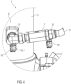
- FIG 3 a section of a vehicle 1 with a second embodiment of a protective device 2 according to the invention is shown.
- Figure 4 shows an enlarged section of this section.
- the protective device 2 comprises a pressure line coupling structure 12 arranged on the connection 9 of the securing element 7 provided for coupling to the pressure line 6, which leads to a fluidic coupling of the pressure line 6 with a further line coupling structure 11.2 arranged on an end of the pressure compensation line 11 facing away from the line coupling structure 11.1 is trained.
- the pressure line coupling structure 12 is also designed, for example, as a measuring coupling.
- the line coupling structure 11.2 includes a corresponding valve, which only opens when coupled to the pressure line coupling structure 12.
- the line coupling structure 11.1 can also include such a valve. If both line coupling structures 11.1, 11.2 have such a valve, a user can couple the pressure compensation line 11 in any order, always preventing hydraulic fluid from escaping from the pressure compensation line 11.
Landscapes
- Engineering & Computer Science (AREA)
- Physics & Mathematics (AREA)
- Fluid Mechanics (AREA)
- Mechanical Engineering (AREA)
- General Engineering & Computer Science (AREA)
- Chemical & Material Sciences (AREA)
- Analytical Chemistry (AREA)
- Fluid-Pressure Circuits (AREA)
Description
- Die Erfindung betrifft eine Schutzvorrichtung für ein hydraulisches oder pneumatisches System gemäß dem Oberbegriff des Anspruchs 1.
- Die Erfindung betrifft weiterhin ein Verfahren zum Betrieb einer solchen Schutzvorrichtung und ein Fahrzeug, umfassend zumindest eine solche Schutzvorrichtung.
- Aus der
DE 10 2007 017 472 A1 ist ein hydraulisches System zum Kippen einer auf einem Kipperfahrzeug befindlichen Kippbrücke bekannt. Das System umfasst einen Hydraulikzylinder als Kippantriebsaggregat für die Kippbrücke, der aus einer normalen Fahrbetriebsstellung in eine Kippbetriebsstellung überführbar ist. Weiterhin umfasst das System ein mit dem Hydraulikzylinder in Hydraulikverbindung stehendes Kippventil zur Steuerung des Hub- und Senkbetriebs des Hydraulikzylinders, einen mit dem Kippventil in Verbindung stehenden Hydraulikflüssigkeitstank und eine mit dem Tank und dem Kippventil in Verbindung stehende Hydraulikpumpe. Zwischen dem Hydraulikzylinder und dem Tank ist ein das Kippventil umgehendes, druckabhängig wirkendes Sicherungsventil vorgesehen, das derart ausgelegt ist, dass es bei in Fahrbetriebsstellung befindlichem Hydraulikzylinder Druckschwankungen, die zwischen Hydraulikzylinder und Kippventil auftreten, zum Tank hin ableitet. - Weiterhin ist aus der
DE 298 15 498 U1 eine Druckschaltventilanordnung mit Überlastsicherungsfunktion für einen hydraulischen Hubzylinder einer hydraulischen Kippeinrichtung eines Fahrzeugs bekannt, wobei die Druckschaltventilanordnung eine Versorgungsleitung für eine Zufuhr eines hydraulischen Druckmediums von einer das Druckmedium aus einem Behälter fördernden Pumpe zu dem hydraulischen Hubzylinder und in der Versorgungsleitung ein in Richtung zu dem hydraulischen Hubzylinder zu öffnendes Rückschlagventil aufweist. Die Druckschaltventilanordnung weist ferner eine zwischen der Pumpe und dem Rückschlagventil von der Versorgungsleitung abgezweigte und zu dem Behälter führende Umlaufleitung und in der Umlaufleitung ein Überdruckventil auf. Das Überdruckventil öffnet gegen eine Kraft einer Ventilschließfeder zu dem Behälter hin, wenn ein Druck in der Versorgungsleitung einen von der Kraft der Ventilschließfeder abhängigen Bezugsdruckwert überschreitet. Ferner weist die Druckschaltventilanordnung eine mit dem Überdruckventil zusammenwirkende Einrichtung auf, die nach dem Öffnen des Überdruckventils dieses in der geöffneten Stellung hält, bis der in der Versorgungsleitung zwischen dem Rückschlagventil und dem hydraulischen Hubzylinder herrschende Druck durch Ableitung von Druckmedium vom hydraulischen Hubzylinder unter einen bestimmten Wert abgesenkt wird. Weiterhin ist eine mittels Steuermitteln elektromotorisch steuerbare Stelleinrichtung zur Beeinflussung eines Spannzustands der Ventilschließfeder des Überdruckventils vorgesehen. - Die
CN 201 041 175 Y beschreibt eine automatische Schutzvorrichtung bei einem Platzen einer hydraulischen Hochdruckölleitung für ein Kipperfahrzeug. Die Schutzvorrichtung umfasst ein Ventil, wobei bei einem Platzen der Hochdruckölleitung das Ventil der Schutzvorrichtung automatisch geschlossen wird und ein Ölrücklaufweg eines angehobenen Ölzylinders geschlossen wird. - Weitere Schutzvorrichtungen für hydraulische oder pneumatische Systeme sind aus der
FI 113 691 B AU 2009 100 917 A4 US 3 228 658 A und derUS 5 215 178 A bekannt. - Der Erfindung liegt die Aufgabe zu Grunde, eine gegenüber dem Stand der Technik verbesserte Schutzvorrichtung für ein hydraulisches oder pneumatisches System, ein verbessertes Verfahren zum Betrieb einer solchen Schutzvorrichtung und ein verbessertes Fahrzeug anzugeben.
- Die Aufgabe wird erfindungsgemäß gelöst durch eine Schutzvorrichtung, welche die im Anspruch 1 angegebenen Merkmale aufweist, durch ein Verfahren, welches die im Anspruch 6 angegebenen Merkmale aufweist, und durch ein Fahrzeug, welches die im Anspruch 8 angegebenen Merkmale aufweist.
- Die Schutzvorrichtung ist für ein hydraulisches oder pneumatisches System, welches einen hydraulischen oder pneumatischen Aktor und einen Tank zur Bevorratung von Hydraulikflüssigkeit oder eines Gases umfasst, vorgesehen. Die Schutzvorrichtung umfasst ein Sicherungselement, eine Druckleitung und ein zumindest ein Druckausgleichsventil umfassendes Druckausgleichselement. Dabei ist der Aktor mittels des Sicherungselements und der Druckleitung mit dem Tank gekoppelt oder koppelbar. Das Sicherungselement umfasst zumindest ein Ventil, welches während eines Normbetriebs geöffnet ist und bei Erreichen eines definierten Druckunterschieds, bei welchem ein Druck der Hydraulikflüssigkeit oder des Gases innerhalb des Aktors größer ist als ein Druck innerhalb eines dem Tank zugewandten Abschnitts der Druckleitung, einen Durchlass zwischen dem Aktor und dem Tank verschließt. Das Druckausgleichselement ist fluidisch zumindest mittelbar mit einem zur Kopplung mit dem Aktor vorgesehenen Anschluss des Sicherungselements gekoppelt.
- Die Schutzvorrichtung ermöglicht mittels des Sicherungselements bei definierten Druckabweichungen zwischen einer Aktorseite und einer Tankseite, das heißt bei Abweichungen vom Normbetrieb, in welchem die Druckabweichungen einen vorgegebenen Grenzwert nicht überschreiten, dass der Aktor von dem Tank bzw. der Druckleitung fluidisch getrennt wird. Dies ist besonders dann vorteilhaft, wenn auf der Tankseite ein Leck auftritt, beispielsweise durch Beschädigung der Druckleitung oder des Tanks selbst, da aufgrund des Verschlusses des Sicherungselements ein Austritt von Hydraulikflüssigkeit oder Gas aus dem Aktor und eine daraus resultierende ungewollte Rückbewegung des Aktors in eine drucklose Ausgangsposition vermieden werden. Somit kann eine ungewollte Bewegung eines mit dem Aktor in seiner Position veränderlichen Bauteils, beispielsweise einer Kippmulde oder eines Auslegers eines Fahrzeugs, vermieden werden. Hieraus resultiert eine erhöhte Sicherheit für Personen und eine Gefahr einer Beschädigung des Bauteils und anderer Objekte in dessen Umgebung wird wirkungsvoll vermieden.
- Das Sicherungselement ist beispielsweise als so genannte Rohrbruchsicherung ausgebildet, welche im Allgemeinen ein Gehäuse, ein Verschlusselement und einen Federmechanismus umfasst. Fällt der Druck in der Druckleitung gegenüber dem Druck im Aktor ab, bewegt der Federmechanismus das Verschlusselement und dieses schließt den Durchlass. Hat eine solche Rohrbruchsicherung ausgelöst, kann diese nur durch eine erneute hydraulisch oder pneumatisch durchgeführte Bewegung des Aktors in Richtung von dessen Endanschlag wieder geöffnet werden, indem bei dieser Bewegung ein Druck in der Druckleitung aufgebaut wird, welcher die Verschlusskappe gegen den Federmechanismus öffnet.
- Jedoch kann es auch ohne Vorhandensein eines Lecks bei einer hydraulisch oder pneumatisch durchgeführten Bewegung des Aktors zum Zeitpunkt eines Erreichens des Endanschlags des Aktors zu einer Druckabweichung kommen, welche zum Auslösen des Sicherungselements führt. Aufgrund des Erreichens des Endanschlags ist keine weitere hydraulisch oder pneumatisch durchgeführte Bewegung des Aktors in diese Richtung möglich, so dass das Sicherungselement nicht wieder geöffnet werden kann und eine Bewegung des Aktors in seine Ausgangsposition nicht möglich ist.
- Dieses Problem wird durch das Druckausgleichselement gelöst, welches bei seiner Öffnung eine Druckverringerung auf der Aktorseite bis zum Erreichen des an der Tankseite vorliegenden Drucks und somit eine Bewegung des Aktors in seine Ausgangsposition oder Nullposition ermöglicht. Bei erneuter hydraulischer oder pneumatischer Beaufschlagung der Druckleitung kann ein Druck in der Druckleitung aufgebaut werden, welcher das Sicherungselement öffnet. Auch ermöglicht das Druckausgleichselement die Bewegung des Aktors in seine Ausgangsposition oder Nullposition, wenn ein Leck auf der Tankseite vorliegt. Somit kann ein mit dem Aktor gekoppeltes Bauteil in eine sichere Ausgangslage bewegt werden.
- Weiterhin umfasst die Schutzvorrichtung eine Druckausgleichsleitung mit einer Leitungskoppelstruktur und eine an dem Druckausgleichselement angeordnete und zu dieser Leitungskoppelstruktur komplementäre Elementkoppelstruktur. Ist die Druckausgleichsleitung mit dem Druckausgleichselement gekoppelt, kann über diese in einfacher und zuverlässiger Weise eine in dem Aktor befindliche Hydraulikflüssigkeit oder ein in dem Aktor befindliches Gas in einen dafür vorgesehenen Auffangbehälter geführt werden, so dass eine Kontamination einer Umgebung des hydraulischen oder pneumatischen Systems mit Hydraulikflüssigkeit oder Gas und daraus resultierende Umweltschädigungen sowie Gefahren für Personen wirkungsvoll vermieden werden können.
- Zusätzlich umfasst die Schutzvorrichtung eine an einem zur Kopplung mit der Druckleitung vorgesehenen Anschluss des Sicherungselements angeordnete Druckleitungskoppelstruktur, welche zu einer fluidischen Kopplung der Druckleitung mit einer an einem der Leitungskoppelstruktur abgewandten Ende der Druckausgleichsleitung angeordneten weiteren Leitungskoppelstruktur ausgebildet ist. Auch ein somit erzeugter Bypass um das Sicherungselement ermöglicht bei Öffnung des Druckausgleichselements eine Rückführung der Hydraulikflüssigkeit oder des Gases in den Tank und vereinfacht so eine sichere Verringerung des Drucks auf der Aktorseite bei weiterer Verringerung einer Kontaminationsgefahr der Umgebung. Hierbei können eine Länge der Druckausgleichsleitung minimiert und daraus folgend eine Handhabung sowie ein Transport derselben signifikant erleichtert werden.
- In einer möglichen Ausgestaltung der Schutzvorrichtung befindet sich das Druckausgleichsventil in einem ungekoppelten Zustand von Druckausgleichsleitung und Druckausgleichselement automatisch in einem geschlossenen Zustand. Das Druckausgleichsventil umfasst einen Betätigungsabschnitt und die Leitungskoppelstruktur umfasst ein zu dem Betätigungsabschnitt komplementäres Betätigungselement, wobei das Betätigungselement im gekoppelten Zustand von Druckausgleichsleitung und Druckausgleichselement derart auf den Betätigungsabschnitt wirkt, dass sich das Druckausgleichsventil in einem geöffneten Zustand befindet. Dies ermöglicht einen sicheren Verschluss des Druckausgleichselements und dass erst bei einer Kopplung desselben mit der Druckausgleichsleitung eine Öffnung desselben erfolgt. Daraus resultiert eine einfache und vor Fehlern geschützte Bedienung durch einen Anwender, so dass die zuvor genannte Kontamination der Umgebung und daraus resultierende Folgen zuverlässig vermieden werden können.
- In einer weiteren möglichen Ausgestaltung der Schutzvorrichtung ist das Druckausgleichselement eine Messkupplung, auch als Schraubkupplung oder Diagnosekupplung bezeichnet. Eine solche Messkupplung umfasst ein mechanisch entsperrbares Rückschlagventil, ist kostengünstig verfügbar und in einfacher und zuverlässiger Weise mit dem hydraulischen oder pneumatischen System koppelbar.
- In einer weiteren möglichen Ausgestaltung der Schutzvorrichtung ist die Druckleitungskoppelstruktur als Messkupplung ausgebildet. Insbesondere umfasst die Messkupplung ein mechanisch entsperrbares Rückschlagventil, ist kostengünstig verfügbar und in einfacher und zuverlässiger Weise mit dem hydraulischen oder pneumatischen System koppelbar.
- In einer weiteren möglichen Ausgestaltung der Schutzvorrichtung umfasst diese eine Fördereinheit zur Förderung von Hydraulikflüssigkeit oder Gas aus dem Tank in den Aktor, um die hydraulische oder pneumatische Beaufschlagung der Druckleitung und des Aktors zu realisieren.
- In dem Verfahren zum Betrieb der zuvor beschriebenen Schutzvorrichtung ist das Sicherungselement während des Normbetriebs automatisch geöffnet. Das Sicherungselement wird bei Erreichen eines definierten Druckunterschieds, bei welchem ein Druck der Hydraulikflüssigkeit oder des Gases innerhalb des Aktors größer ist als ein Druck innerhalb eines dem Tank zugewandten Abschnitts der Druckleitung, ausgelöst und verschließt dadurch einen Durchlass zwischen dem Aktor und dem Tank.
- Erfindungsgemäß wird dann, wenn die Druckleitung sowie deren Verbindung mit dem Sicherungselement und dem Tank leckfrei sind, das zumindest eine Druckausgleichsventil des Druckausgleichselements zumindest solange geöffnet, bis der Druck der Hydraulikflüssigkeit oder des Gases innerhalb des Aktors zumindest gleich groß wie der Druck innerhalb des dem Tank zugewandten Abschnitts der Druckleitung ist.
- Mittels des Verfahrens wird auch nach der Auslösung des Sicherungselements eine Bewegung des Aktors in seine Ausgangsposition oder Nullposition ermöglicht. Somit kann ein mit dem Aktor gekoppeltes Bauteil in eine sichere Ausgangslage bewegt werden.
- Weiterhin wird zur Öffnung des Druckausgleichventils die Leitungskoppelstruktur der Druckausgleichsleitung mit der an dem Druckausgleichselement angeordneten und zu dieser Leitungskoppelstruktur komplementären Elementkoppelstruktur gekoppelt. Während dieser Kopplung wird ein Betätigungsabschnitt des Druckausgleichselements von einem Betätigungselement der Leitungskoppelstruktur derart betätigt, dass das Druckausgleichsventil geöffnet wird. Dies ermöglicht einen sicheren Verschluss des Druckausgleichselements und dass erst bei einer Kopplung desselben mit der Druckausgleichsleitung eine Öffnung desselben erfolgt. Daraus resultiert eine einfache und vor Fehlern geschützte Bedienung durch einen Anwender, so dass die zuvor genannte Kontamination der Umgebung und daraus resultierende Folgen zuverlässig vermieden werden können.
- In einer weiteren möglichen Ausgestaltung des Verfahrens wird vor der Kopplung der Druckausgleichsleitung mit dem Druckausgleichselement die Druckausgleichsleitung mit dem der Leitungskoppelstruktur abgewandten Ende fluidisch mit der Druckleitung gekoppelt. Auch ein somit erzeugter Bypass um das Sicherungselement ermöglicht bei Öffnung des Druckausgleichselements eine Rückführung der Hydraulikflüssigkeit oder des Gases in den Tank und vereinfacht so eine sichere Verringerung des Drucks auf der Aktorseite bei weiterer Verringerung einer Kontaminationsgefahr der Umgebung. Aufgrund einer möglichen Minimierung einer Länge der Druckausgleichsleitung werden eine Handhabung sowie ein Transport derselben signifikant erleichtert.
- Das erfindungsgemäße Fahrzeug umfasst ein hydraulisches oder pneumatisches System und zumindest eine zuvor beschriebene Schutzvorrichtung. Die Schutzvorrichtung ermöglicht mittels des Sicherungselements bei definierten Druckabweichungen zwischen der Aktorseite und der Tankseite, dass der Aktor von dem Tank bzw. der Druckleitung fluidisch getrennt wird. Dies ist besonders dann vorteilhaft, wenn auf der Tankseite ein Leck auftritt, beispielsweise durch Beschädigung der Druckleitung oder des Tanks selbst, da aufgrund des Verschlusses des Sicherungselements der Austritt von Hydraulikflüssigkeit oder Gas aus dem Aktor und eine daraus resultierende ungewollte Rückbewegung des Aktors in eine drucklose Ausgangsposition vermieden werden. Somit kann eine ungewollte Bewegung eines mit dem Aktor in seiner Position veränderlichen Bauteils des Fahrzeugs vermieden werden. Hieraus resultiert eine erhöhte Sicherheit für Personen und eine Gefahr einer Beschädigung des Bauteils und anderer Objekte in dessen Umgebung wird wirkungsvoll vermieden. Weiterhin wird mittels der Schutzvorrichtung auch nach der Auslösung des Sicherungselements eine Bewegung des Aktors in seine Ausgangsposition oder Nullposition ermöglicht. Somit kann das mit dem Aktor gekoppelte Bauteil in eine sichere Ausgangslage bewegt werden.
- In einer möglichen Ausgestaltung des Fahrzeugs umfasst dieses eine Kippmulde, welche mittels eines hydraulischen oder pneumatischen Aktors des hydraulischen oder pneumatischen Systems, beispielsweise eines Hydraulik- oder Pneumatikzylinders, aus einer Ausgangsposition in eine gekippte Position überführbar ist. Das Fahrzeug kann hierbei auch ein Fahrzeuggespann sein, bei welchem die Kippmulde Bestandteil eines Anhängers, beispielsweise Aufliegers ist. Der Aktor und das mit diesem gekoppelte Sicherungselement sind mittels des Druckschlauchs mit dem Tank gekoppelt, wobei der Tank bei einem Fahrzeuggespann an einer Zugmaschine angeordnet sein kann. Die Schutzvorrichtung ermöglicht bei einem derart ausgebildeten Fahrzeug aufgrund des Sicherungselements einerseits, dass bei einem Leck in der Druckleitung eine unkontrollierte Bewegung der Kippmulde in ihre Ausgangsposition oder Nullposition und daraus resultierende Gefahren vermieden werden. Weiterhin werden ein Austritt von Hydraulikflüssigkeit oder Gas aus dem Aktor in eine Umgebung des Fahrzeugs vermieden. Zusätzlich ermöglicht die Schutzvorrichtung auch bei im Endanschlag befindlichen Aktor und ausgelöstem Sicherungselement durch Öffnen des Druckausgleichselements eine kontrollierte Bewegung der Kippmulde in ihre Ausgangsposition oder Nullposition.
- In einer weiteren möglichen Ausgestaltung des Fahrzeugs umfasst dieses zumindest einen Ausleger, welche mittels eines hydraulischen oder pneumatischen Aktors des hydraulischen oder pneumatischen Systems aus einer Ausgangsposition in eine von dieser abweichende Position überführbar ist. Beispielsweise ist das Fahrzeug ein Bagger oder Kran. Auch bei einer solchen Ausbildung des Fahrzeugs ermöglicht die Schutzvorrichtung aufgrund des Sicherungselements einerseits, dass bei einem Leck in der Druckleitung eine unkontrollierte Bewegung des Auslegers in eine Ausgangsposition oder Nullposition und daraus resultierende Gefahren vermieden werden. Weiterhin werden ein Austritt von Hydraulikflüssigkeit oder Gas aus dem Aktor in eine Umgebung des Fahrzeugs vermieden. Zusätzlich ermöglicht die Schutzvorrichtung auch bei im Endanschlag befindlichen Aktor und ausgelöstem Sicherungselement durch Öffnen des Druckausgleichselements eine kontrollierte Bewegung des Auslegers in seine Ausgangsposition oder Nullposition.
- Abweichend von der vorherigen Beschreibung kann die Schutzvorrichtung auch Bestandteil anderer Vorrichtungen mit einem hydraulischen oder pneumatischen System sein, wie zum Beispiel einer Hebe- oder Arbeitsbühne.
- Vorteilhafte Ausgestaltungen der Erfindung sind Gegenstand der Unteransprüche.
- Ausführungsbeispiele der Erfindung werden im Folgenden anhand von Zeichnungen näher erläutert.
- Darin zeigen:
- Figur 1
- schematisch einen Ausschnitt eines Fahrzeugs mit einem ersten nicht erfindungsgemäßen Ausführungsbeispiel einer Schutzvorrichtung,
- Figur 2
- schematisch einen vergrößerten Ausschnitt des Ausschnitts gemäß
Figur 1 , - Figur 3
- schematisch einen Ausschnitt eines Fahrzeugs mit einem zweiten erfindungsgemäßen Ausführungsbeispiel einer Schutzvorrichtung und
- Figur 4
- schematisch einen vergrößerten Ausschnitt des Ausschnitts gemäß
Figur 3 . - Einander entsprechende Teile sind in allen Figuren mit den gleichen Bezugszeichen versehen.
- In
Figur 1 ist ein Ausschnitt eines Fahrzeugs 1 mit einem ersten nicht erfindungsgemäßen Ausführungsbeispiel einer Schutzvorrichtung 2 dargestellt.Figur 2 zeigt einen vergrößerten Ausschnitt dieses Ausschnitts. - Das Fahrzeug 1 ist beispielsweise ein Fahrzeuggespann, umfassend ein nicht näher dargestelltes Zugfahrzeug und einen nicht näher dargestellten Auflieger mit einer Kippmulde. In nicht näher dargestellten Ausführungsbeispielen kann das Fahrzeug 1 auch jedes andere denkbare Fahrzeug sein.
- Zu einer Entladung der Kippmulde, insbesondere zur Entladung von Schüttgut, ist eine Bewegung der Kippmulde aus einer Ausgangsposition oder Nullposition in eine gekippte Position erforderlich, welche vorliegend mittels eines an dem Auflieger angeordneten hydraulischen Aktors 3, insbesondere eines Hydraulikzylinders, erfolgt. In nicht näher dargestellten Ausführungsbeispielen kann der Aktor 3 auch pneumatisch betätigt sein.
- Zur Erzeugung der Bewegung umfasst das Fahrzeug 1, im beschriebenen Ausführungsbeispiel insbesondere das Zugfahrzeug, einen Tank zur Bevorratung einer Hydraulikflüssigkeit sowie eine Fördereinheit zur Förderung von Hydraulikflüssigkeit aus dem Tank in den Aktor 3.
- Weiterhin umfasst das Fahrzeug 1, im beschriebenen Ausführungsbeispiel insbesondere der Auflieger, ein Koppelelement 4 zur fluidischen Kopplung des Aktors 3 mit einer mit dem Tank gekoppelten Druckleitung 5. An einer zur Kopplung mit dieser Druckleitung 5 abgewandten Seite des Koppelelements 4 ist dieses mit einer weiteren Druckleitung 6 fluidisch gekoppelt, welche wiederum mit dem Aktor 3 fluidisch gekoppelt ist.
- Zwischen dem Aktor 3 und der Druckleitung 6 ist ein Sicherungselement 7 angeordnet und fluidisch mit einem Anschluss 8 des Aktors 3 und einem Anschluss 9 der Druckleitung 6 gekoppelt.
- Das Sicherungselement 7 umfasst in nicht näher dargestellter Weise zumindest ein Ventil, welches während eines Normbetriebs geöffnet ist und bei Erreichen eines definierten Druckunterschieds, bei welchem ein Druck der Hydraulikflüssigkeit innerhalb des Aktors 3 größer ist als ein Druck innerhalb der Druckleitungen 5, 6, einen Durchlass zwischen dem Aktor 3 und dem Tank verschließt. Somit kann dann, wenn ausgehend von dem Sicherungselement 7 auf einer Tankseite ein Leck auftritt, beispielsweise durch Beschädigung einer der Druckleitungen 5, 6 oder des Tanks selbst, aufgrund des Verschlusses des Sicherungselements 7 ein Austritt von Hydraulikflüssigkeit aus dem Aktor 3 und eine daraus resultierende ungewollte Rückbewegung des Aktors 3 in seine drucklose Ausgangsposition oder Nullposition vermieden werden. Somit kann eine ungewollte Bewegung der Kippmulde vermieden werden.
- Das Sicherungselement 7 ist beispielsweise als so genannte Rohrbruchsicherung ausgebildet, welche ein Gehäuse und als Ventil ein Verschlusselement und einen Federmechanismus umfasst. Fällt der Druck in der Druckleitung 6 gegenüber dem Druck im Aktor 3 ab, bewegt der Federmechanismus das Verschlusselement und dieses schließt den Durchlass. Hat eine solche Rohrbruchsicherung ausgelöst, kann diese nur durch eine erneute hydraulisch oder pneumatisch durchgeführte Bewegung des Aktors 3 in Richtung von dessen Endanschlag wieder geöffnet werden, indem bei dieser Bewegung ein Druck in der Druckleitung 6 aufgebaut wird, welcher die Verschlusskappe gegen den Federmechanismus öffnet.
- Jedoch kann es auch ohne Vorhandensein eines Lecks bei der hydraulisch durchgeführten Bewegung der Kippmulde zum Zeitpunkt eines Erreichens des Endanschlags des Aktors 3 zu einer Druckabweichung kommen, welche zum Auslösen des Sicherungselements 7 führt. Aufgrund des Erreichens des Endanschlags ist keine weitere hydraulisch durchgeführte Bewegung des Aktors 3 in diese Richtung möglich, so dass das Sicherungselement 7 nicht wieder geöffnet werden kann und eine Bewegung des Aktors 3 in seine Ausgangsposition nicht möglich ist.
- Um dennoch eine Öffnung des Sicherungselements 7 zu ermöglichen, ist ein Druckausgleichselement 10 fluidisch zumindest mittelbar mit dem Anschluss 8 gekoppelt. Das Druckausgleichselement 10 umfasst ein nicht näher dargestelltes Druckausgleichsventil, welches bei seiner Öffnung eine Druckverringerung auf der Aktorseite zumindest bis zum Erreichen des an der Tankseite vorliegenden Drucks und somit eine Bewegung des Aktors 3 und der Kippmulde in ihre Ausgangsposition oder Nullposition ermöglicht. Bei erneuter hydraulischer oder pneumatischer Beaufschlagung der Druckleitungen 5, 6 kann anschließend wieder ein Druck in den Druckleitungen 5, 6 aufgebaut werden, welcher das Sicherungselement 7 öffnet. Auch ermöglicht das Druckausgleichselement 10 eine gesteuerte Bewegung des Aktors 3 und der Kippmulde in ihre Ausgangsposition oder Nullposition, wenn ein Leck auf der Tankseite vorliegt. Somit kann die Kippmulde in eine sichere Ausgangslage bewegt werden.
- Das Druckausgleichselement 10 ist im dargestellten Ausführungsbeispiel als Messkupplung, auch als Schraubkupplung oder Diagnosekupplung bezeichnet, ausgebildet und umfasst als Druckausgleichsventil ein mechanisch entsperrbares Rückschlagventil.
- An das Druckausgleichselement 10 ist eine Druckausgleichsleitung 11 koppelbar, wobei die Druckausgleichsleitung 11 hierzu eine Leitungskoppelstruktur 11.1 umfasst, welche komplementär zu einer Elementkoppelstruktur 10.1 des Druckausgleichselements 10 ausgebildet ist.
- Das Druckausgleichsventil befindet sich in einem ungekoppelten Zustand von Druckausgleichsleitung 11 und Druckausgleichselement 10 automatisch in einem geschlossenen Zustand. Wird jedoch die Druckausgleichsleitung 11 mit dem Druckausgleichselement 10 gekoppelt, wird ein nicht näher dargestellter Betätigungsabschnitt des Druckausgleichselements 10 von einem ebenfalls nicht näher dargestellten Betätigungselement der Leitungskoppelstruktur 11.1 derart betätigt, dass das Druckausgleichsventil geöffnet wird.
- Um eine Kontamination einer Umgebung des Fahrzeugs 1 mit austretender Hydraulikflüssigkeit zu vermeiden, ist eine an dem Tank ausgebildete Tankkoppelstruktur vorgesehen, welche zu einer fluidischen Kopplung des Tanks mit einem der Leitungskoppelstruktur 11.1 abgewandten Ende der Druckausgleichsleitung 11 ausgebildet ist. Dabei erfolgt vor der Kopplung der Druckausgleichsleitung 11 mit dem Druckausgleichselement 10 die fluidische Kopplung der Druckausgleichsleitung 11 mit dem Tank. Somit kann bei der Durchführung des Druckausgleichs aus dem Aktor 3 austretende Hydraulikflüssigkeit sicher in den Tank zurückgeführt werden.
- In
Figur 3 ist ein Ausschnitt eines Fahrzeugs 1 mit einem zweiten erfindungsgemäßen Ausführungsbeispiel einer Schutzvorrichtung 2 dargestellt.Figur 4 zeigt einen vergrößerten Ausschnitt dieses Ausschnitts. - Im Unterschied zu dem in den
Figuren 1 und2 dargestellten ersten Ausführungsbeispiel umfasst die Schutzvorrichtung 2 eine an dem zur Kopplung mit der Druckleitung 6 vorgesehenen Anschluss 9 des Sicherungselements 7 angeordnete Druckleitungskoppelstruktur 12, welche zu einer fluidischen Kopplung der Druckleitung 6 mit einer an einem der Leitungskoppelstruktur 11.1 abgewandten Ende der Druckausgleichsleitung 11 angeordneten weiteren Leitungskoppelstruktur 11.2 ausgebildet ist. - Auch die Druckleitungskoppelstruktur 12 ist beispielsweise als Messkupplung ausgebildet.
- Um nach der Kopplung der Druckausgleichsleitung 11 mit dem Druckausgleichselement 10 und vor der Kopplung mit der Druckleitungskoppelstruktur 12 ein Austreten der Hydraulikflüssigkeit aus der Druckausgleichsleitung 11 zu vermeiden, umfasst die Leitungskoppelstruktur 11.2 ein entsprechendes Ventil, welches erst bei Kopplung mit der Druckleitungskoppelstruktur 12 öffnet. Alternativ oder zusätzlich kann auch die Leitungskoppelstruktur 11.1 ein solches Ventil umfassen. Weisen beide Leitungskoppelstrukturen 11.1, 11.2 ein solches Ventil auf, kann ein Nutzer die Druckausgleichsleitung 11 in einer beliebigen Reihenfolge koppeln, wobei stets ein Austreten von Hydraulikflüssigkeit aus der Druckausgleichsleitung 11 vermieden wird.
-
- 1
- Fahrzeug
- 2
- Schutzvorrichtung
- 3
- Aktor
- 4
- Koppelelement
- 5
- Druckleitung
- 6
- Druckleitung
- 7
- Sicherungselement
- 8
- Anschluss
- 9
- Anschluss
- 10
- Druckausgleichselement
- 10.1
- Elementkoppelstruktur
- 11
- Druckausgleichsleitung
- 11.1
- Leitungskoppelstruktur
- 11.2
- Leitungskoppelstruktur
- 12
- Druckleitungskoppelstruktur
Claims (10)
- Schutzvorrichtung (2) für ein hydraulisches oder pneumatisches System, welches einen hydraulischen oder pneumatischen Aktor (3) und einen Tank zur Bevorratung von Hydraulikflüssigkeit oder eines Gases umfasst,mit einem Sicherungselement (7), einer Druckleitung (6) und einem zumindest ein Druckausgleichsventil umfassenden Druckausgleichselement (10), wobei- der Aktor (3) mittels des Sicherungselements (7) und der Druckleitung (6) mit dem Tank koppelbar ist,- das Sicherungselement (7) zumindest ein Ventil umfasst, welches während eines Normbetriebs geöffnet ist und bei Erreichen eines definierten Druckunterschieds, bei welchem ein Druck der Hydraulikflüssigkeit oder des Gases innerhalb des Aktors (3) größer ist als ein Druck innerhalb eines dem Tank zugewandten Abschnitts der Druckleitung (6), einen Durchlass zwischen dem Aktor (3) und dem Tank verschließt, und- das Druckausgleichselement (10) fluidisch zumindest mittelbar mit einem zur Kopplung mit dem Aktor (3) vorgesehenen Anschluss (8) des Sicherungselements (7) gekoppelt istgekennzeichnet durch- eine Druckausgleichsleitung (11) mit einer Leitungskoppelstruktur (11.1),- eine an dem Druckausgleichselement (10) angeordnete und zu dieser Leitungskoppelstruktur (11.1) komplementäre Elementkoppelstruktur (10.1) und- eine an einem zur Kopplung mit der Druckleitung (6) vorgesehenen Anschluss (9) des Sicherungselements (7) angeordnete Druckleitungskoppelstruktur (12), welche zu einer fluidischen Kopplung der Druckleitung (6) mit einer an einem der Leitungskoppelstruktur (11.1) abgewandten Ende der Druckausgleichsleitung (11) angeordneten weiteren Leitungskoppelstruktur (11.2) ausgebildet ist.
- Schutzvorrichtung (2) nach Anspruch 1, dadurch gekennzeichnet, dass- sich das Druckausgleichsventil in einem ungekoppelten Zustand von Druckausgleichsleitung (11) und Druckausgleichselement (10) automatisch in einem geschlossenen Zustand befindet,- das Druckausgleichsventil einen Betätigungsabschnitt und die Leitungskoppelstruktur (11.1) ein zu dem Betätigungsabschnitt komplementäres Betätigungselement umfassen und- das Betätigungselement im gekoppelten Zustand von Druckausgleichsleitung (11) und Druckausgleichselement (10) derart auf den Betätigungsabschnitt wirkt, dass sich das Druckausgleichsventil in einem geöffneten Zustand befindet.
- Schutzvorrichtung (2) nach einem der vorhergehenden Ansprüche, wobei das Druckausgleichselement (10) eine Messkupplung ist.
- Schutzvorrichtung (2) nach einem der vorhergehenden Ansprüche, dadurch gekennzeichnet, dass die Druckleitungskoppelstruktur (12) als Messkupplung ausgebildet ist.
- Schutzvorrichtung (2) nach einem der vorhergehenden Ansprüche, gekennzeichnet durch eine Fördereinheit zur Förderung von Hydraulikflüssigkeit oder Gas aus dem Tank in den Aktor (3).
- Verfahren zum Betrieb einer Schutzvorrichtung (2) nach einem der vorhergehenden Ansprüche, wobei- das Sicherungselement (7) während des Normbetriebs automatisch geöffnet ist,- das Sicherungselement (7) bei Erreichen eines definierten Druckunterschieds, bei welchem ein Druck der Hydraulikflüssigkeit oder des Gases innerhalb des Aktors (3) größer ist als ein Druck innerhalb eines dem Tank zugewandten Abschnitts der Druckleitung (6), ausgelöst wird und dieses einen Durchlass zwischen dem Aktor (3) und dem Tank verschließt, dadurch gekennzeichnet, dass- dann, wenn die Druckleitung (6) sowie deren Verbindung mit dem Sicherungselement (7) und dem Tank leckfrei sind, das zumindest eine Druckausgleichsventil des Druckausgleichselements (10) zumindest solange geöffnet wird, bis der Druck der Hydraulikflüssigkeit oder des Gases innerhalb des Aktors (3) zumindest gleich groß wie der Druck innerhalb des dem Tank zugewandten Abschnitts der Druckleitung (6) ist, wobei zur Öffnung des Druckausgleichsventils die Leitungskoppelstruktur (11.1) der Druckausgleichsleitung (11) mit der an dem Druckausgleichselement (10) angeordneten und zu dieser Leitungskoppelstruktur (11.1) komplementären Elementkoppelstruktur (10.1) gekoppelt wird und- während der Kopplung ein Betätigungsabschnitt des Druckausgleichselements (10) von einem Betätigungselement der Leitungskoppelstruktur (11.1) derart betätigt wird, dass das Druckausgleichsventil geöffnet wird.
- Verfahren nach Anspruch 6, dadurch gekennzeichnet, dass vor der Kopplung der Druckausgleichsleitung (11) mit dem Druckausgleichselement (10) die Druckausgleichsleitung (11) mit dem der Leitungskoppelstruktur (11.1) abgewandten Ende fluidisch mit der Druckleitung (6) gekoppelt wird.
- Fahrzeug (1), umfassend ein hydraulisches oder pneumatisches System und zumindest eine Schutzvorrichtung (2) gemäß einem der Ansprüche 1 bis 5.
- Fahrzeug (1) nach Anspruch 8, umfassend eine Kippmulde, welche mittels eines hydraulischen oder pneumatischen Aktors (3) des hydraulischen oder pneumatischen Systems aus einer Ausgangsposition in eine gekippte Position überführbar ist.
- Fahrzeug (1) nach Anspruch 8 oder 9, umfassend zumindest einen Ausleger, welcher mittels eines hydraulischen oder pneumatischen Aktors (3) des hydraulischen oder pneumatischen Systems aus einer Ausgangsposition in eine von dieser abweichende Position überführbar ist.
Priority Applications (1)
| Application Number | Priority Date | Filing Date | Title |
|---|---|---|---|
| EP20162146.3A EP3879127B1 (de) | 2020-03-10 | 2020-03-10 | Schutzvorrichtung für ein hydraulisches oder pneumatisches system und fahrzeug |
Applications Claiming Priority (1)
| Application Number | Priority Date | Filing Date | Title |
|---|---|---|---|
| EP20162146.3A EP3879127B1 (de) | 2020-03-10 | 2020-03-10 | Schutzvorrichtung für ein hydraulisches oder pneumatisches system und fahrzeug |
Publications (3)
| Publication Number | Publication Date |
|---|---|
| EP3879127A1 EP3879127A1 (de) | 2021-09-15 |
| EP3879127C0 EP3879127C0 (de) | 2024-02-14 |
| EP3879127B1 true EP3879127B1 (de) | 2024-02-14 |
Family
ID=69804505
Family Applications (1)
| Application Number | Title | Priority Date | Filing Date |
|---|---|---|---|
| EP20162146.3A Active EP3879127B1 (de) | 2020-03-10 | 2020-03-10 | Schutzvorrichtung für ein hydraulisches oder pneumatisches system und fahrzeug |
Country Status (1)
| Country | Link |
|---|---|
| EP (1) | EP3879127B1 (de) |
Citations (1)
| Publication number | Priority date | Publication date | Assignee | Title |
|---|---|---|---|---|
| FI20020281A7 (fi) * | 2002-02-12 | 2003-08-13 | Nummi Oy Ab | Turvaventtiili kippilaitteen hydraulisen teleskooppisylinterin yhteydessä |
Family Cites Families (6)
| Publication number | Priority date | Publication date | Assignee | Title |
|---|---|---|---|---|
| US3228658A (en) * | 1963-12-11 | 1966-01-11 | Applied Power Ind Inc | Hydraulic lift |
| US5215178A (en) * | 1991-03-25 | 1993-06-01 | Mcneilus Truck And Manufacturing, Inc. | Safety valve for discharge chutes on cement mixer |
| DE29815498U1 (de) | 1998-08-28 | 2000-01-27 | Franz Xaver Meiller Fahrzeug- und Maschinenfabrik - GmbH & Co KG, 80997 München | Druckschaltventilanordnung mit Überlastsicherungsfunktion für einen hydraulischen Verbraucher |
| DE102007017472B4 (de) | 2007-04-13 | 2018-05-30 | Franz Xaver Meiller Fahrzeug- Und Maschinenfabrik - Gmbh & Co Kg | Entlastung eines hydraulischen Kippsystems |
| CN201041175Y (zh) | 2007-05-10 | 2008-03-26 | 赵义 | 重型自卸车液压高压油管爆裂自动保护装置 |
| AU2009100917A4 (en) * | 2009-09-11 | 2009-10-22 | Johannes Nijhuis | TSVB (Tipper Body Hose Break Prevention System) |
-
2020
- 2020-03-10 EP EP20162146.3A patent/EP3879127B1/de active Active
Patent Citations (1)
| Publication number | Priority date | Publication date | Assignee | Title |
|---|---|---|---|---|
| FI20020281A7 (fi) * | 2002-02-12 | 2003-08-13 | Nummi Oy Ab | Turvaventtiili kippilaitteen hydraulisen teleskooppisylinterin yhteydessä |
Also Published As
| Publication number | Publication date |
|---|---|
| EP3879127A1 (de) | 2021-09-15 |
| EP3879127C0 (de) | 2024-02-14 |
Similar Documents
| Publication | Publication Date | Title |
|---|---|---|
| EP2569058B1 (de) | Ventil | |
| EP3112230A1 (de) | Feststellbremsmodul, bremsanlage und fahrzeug damit sowie verfahren zum betreiben einer feststellbremseinrichtung mit einem solchen modul | |
| WO2007096099A1 (de) | Steuervorrichtung und hydraulische vorsteuerung | |
| DE202014001328U1 (de) | Schnellkuppler | |
| DE2066194C2 (de) | ||
| EP3879127B1 (de) | Schutzvorrichtung für ein hydraulisches oder pneumatisches system und fahrzeug | |
| EP3608286B1 (de) | Flurförderzeug mit hydraulischem hubsystem und elektronischer fehlfunktionsabsicherung des hubsystems | |
| DE102018126812A1 (de) | Kupplungsvorrichtung, Versorgungsleitung sowie System zur Übertragung eines Mediums | |
| DE102022126034A1 (de) | Ventilanordnung für Arbeitsmaschinen mit ölhydraulischem Werkzeug | |
| DE3204115A1 (de) | Schnellverschlusskupplung | |
| DE10151831B4 (de) | Hydraulikanlage für ein Flurförderzeug | |
| EP4385938B1 (de) | Ventileinrichtung für ein flurförderzeug | |
| DE102007017472B4 (de) | Entlastung eines hydraulischen Kippsystems | |
| DE10104298A1 (de) | Hydraulische Steueranordnung | |
| EP0612645B1 (de) | Druckluftbremse für Schienenfahrzeuge | |
| DE19954584A1 (de) | Schutzeinrichtung für Bremssysteme | |
| DE102014221576A1 (de) | Druckzylinder zur hydraulischen Steuerung von Anbaugeräten an Arbeitsfahrzeugen und hydraulisches Steuerungssystem für Anbaugeräte an Arbeitsfahrzeugen mit derartigen Druckzylindern | |
| EP2639104B1 (de) | Hydrauliksteuerung eines einfach wirkenden Kipperzylinders | |
| DE3937245C2 (de) | Schienenhaken | |
| EP4222410B1 (de) | Kupplungsvorrichtung und kryo-betankungsanordnung | |
| AT409112B (de) | Hydraulische anordnung zur betätigung von beweglichen teilen an fahrzeugen, und vorspannventil für diese anordnung | |
| EP2985473B1 (de) | Hubmodul | |
| DE3443638A1 (de) | Hydraulikbremse fuer fahrzeuge, insbesondere schienenfahrzeuge | |
| DE102008005925B4 (de) | Rückschlagklappe mit Hilfsklappe | |
| EP4686867A1 (de) | Aufnahmekupplungselement zur verbindung einer fluidzuleitung mit einem anschlussstutzen |
Legal Events
| Date | Code | Title | Description |
|---|---|---|---|
| PUAI | Public reference made under article 153(3) epc to a published international application that has entered the european phase |
Free format text: ORIGINAL CODE: 0009012 |
|
| STAA | Information on the status of an ep patent application or granted ep patent |
Free format text: STATUS: THE APPLICATION HAS BEEN PUBLISHED |
|
| AK | Designated contracting states |
Kind code of ref document: A1 Designated state(s): AL AT BE BG CH CY CZ DE DK EE ES FI FR GB GR HR HU IE IS IT LI LT LU LV MC MK MT NL NO PL PT RO RS SE SI SK SM TR |
|
| STAA | Information on the status of an ep patent application or granted ep patent |
Free format text: STATUS: REQUEST FOR EXAMINATION WAS MADE |
|
| 17P | Request for examination filed |
Effective date: 20220103 |
|
| RBV | Designated contracting states (corrected) |
Designated state(s): AL AT BE BG CH CY CZ DE DK EE ES FI FR GB GR HR HU IE IS IT LI LT LU LV MC MK MT NL NO PL PT RO RS SE SI SK SM TR |
|
| GRAP | Despatch of communication of intention to grant a patent |
Free format text: ORIGINAL CODE: EPIDOSNIGR1 |
|
| STAA | Information on the status of an ep patent application or granted ep patent |
Free format text: STATUS: GRANT OF PATENT IS INTENDED |
|
| INTG | Intention to grant announced |
Effective date: 20230919 |
|
| GRAS | Grant fee paid |
Free format text: ORIGINAL CODE: EPIDOSNIGR3 |
|
| GRAA | (expected) grant |
Free format text: ORIGINAL CODE: 0009210 |
|
| STAA | Information on the status of an ep patent application or granted ep patent |
Free format text: STATUS: THE PATENT HAS BEEN GRANTED |
|
| AK | Designated contracting states |
Kind code of ref document: B1 Designated state(s): AL AT BE BG CH CY CZ DE DK EE ES FI FR GB GR HR HU IE IS IT LI LT LU LV MC MK MT NL NO PL PT RO RS SE SI SK SM TR |
|
| REG | Reference to a national code |
Ref country code: GB Ref legal event code: FG4D Free format text: NOT ENGLISH |
|
| REG | Reference to a national code |
Ref country code: CH Ref legal event code: EP |
|
| REG | Reference to a national code |
Ref country code: DE Ref legal event code: R096 Ref document number: 502020006974 Country of ref document: DE |
|
| REG | Reference to a national code |
Ref country code: IE Ref legal event code: FG4D Free format text: LANGUAGE OF EP DOCUMENT: GERMAN |
|
| U01 | Request for unitary effect filed |
Effective date: 20240220 |
|
| U07 | Unitary effect registered |
Designated state(s): AT BE BG DE DK EE FI FR IT LT LU LV MT NL PT SE SI Effective date: 20240229 |
|
| U20 | Renewal fee for the european patent with unitary effect paid |
Year of fee payment: 5 Effective date: 20240318 |
|
| REG | Reference to a national code |
Ref country code: LT Ref legal event code: MG9D |
|
| PG25 | Lapsed in a contracting state [announced via postgrant information from national office to epo] |
Ref country code: IS Free format text: LAPSE BECAUSE OF FAILURE TO SUBMIT A TRANSLATION OF THE DESCRIPTION OR TO PAY THE FEE WITHIN THE PRESCRIBED TIME-LIMIT Effective date: 20240614 |
|
| PG25 | Lapsed in a contracting state [announced via postgrant information from national office to epo] |
Ref country code: GR Free format text: LAPSE BECAUSE OF FAILURE TO SUBMIT A TRANSLATION OF THE DESCRIPTION OR TO PAY THE FEE WITHIN THE PRESCRIBED TIME-LIMIT Effective date: 20240515 |
|
| PG25 | Lapsed in a contracting state [announced via postgrant information from national office to epo] |
Ref country code: HR Free format text: LAPSE BECAUSE OF FAILURE TO SUBMIT A TRANSLATION OF THE DESCRIPTION OR TO PAY THE FEE WITHIN THE PRESCRIBED TIME-LIMIT Effective date: 20240214 Ref country code: RS Free format text: LAPSE BECAUSE OF FAILURE TO SUBMIT A TRANSLATION OF THE DESCRIPTION OR TO PAY THE FEE WITHIN THE PRESCRIBED TIME-LIMIT Effective date: 20240514 |
|
| PG25 | Lapsed in a contracting state [announced via postgrant information from national office to epo] |
Ref country code: ES Free format text: LAPSE BECAUSE OF FAILURE TO SUBMIT A TRANSLATION OF THE DESCRIPTION OR TO PAY THE FEE WITHIN THE PRESCRIBED TIME-LIMIT Effective date: 20240214 |
|
| PG25 | Lapsed in a contracting state [announced via postgrant information from national office to epo] |
Ref country code: RS Free format text: LAPSE BECAUSE OF FAILURE TO SUBMIT A TRANSLATION OF THE DESCRIPTION OR TO PAY THE FEE WITHIN THE PRESCRIBED TIME-LIMIT Effective date: 20240514 Ref country code: NO Free format text: LAPSE BECAUSE OF FAILURE TO SUBMIT A TRANSLATION OF THE DESCRIPTION OR TO PAY THE FEE WITHIN THE PRESCRIBED TIME-LIMIT Effective date: 20240514 Ref country code: IS Free format text: LAPSE BECAUSE OF FAILURE TO SUBMIT A TRANSLATION OF THE DESCRIPTION OR TO PAY THE FEE WITHIN THE PRESCRIBED TIME-LIMIT Effective date: 20240614 Ref country code: HR Free format text: LAPSE BECAUSE OF FAILURE TO SUBMIT A TRANSLATION OF THE DESCRIPTION OR TO PAY THE FEE WITHIN THE PRESCRIBED TIME-LIMIT Effective date: 20240214 Ref country code: GR Free format text: LAPSE BECAUSE OF FAILURE TO SUBMIT A TRANSLATION OF THE DESCRIPTION OR TO PAY THE FEE WITHIN THE PRESCRIBED TIME-LIMIT Effective date: 20240515 Ref country code: ES Free format text: LAPSE BECAUSE OF FAILURE TO SUBMIT A TRANSLATION OF THE DESCRIPTION OR TO PAY THE FEE WITHIN THE PRESCRIBED TIME-LIMIT Effective date: 20240214 |
|
| PG25 | Lapsed in a contracting state [announced via postgrant information from national office to epo] |
Ref country code: PL Free format text: LAPSE BECAUSE OF FAILURE TO SUBMIT A TRANSLATION OF THE DESCRIPTION OR TO PAY THE FEE WITHIN THE PRESCRIBED TIME-LIMIT Effective date: 20240214 |
|
| PG25 | Lapsed in a contracting state [announced via postgrant information from national office to epo] |
Ref country code: PL Free format text: LAPSE BECAUSE OF FAILURE TO SUBMIT A TRANSLATION OF THE DESCRIPTION OR TO PAY THE FEE WITHIN THE PRESCRIBED TIME-LIMIT Effective date: 20240214 |
|
| PG25 | Lapsed in a contracting state [announced via postgrant information from national office to epo] |
Ref country code: SM Free format text: LAPSE BECAUSE OF FAILURE TO SUBMIT A TRANSLATION OF THE DESCRIPTION OR TO PAY THE FEE WITHIN THE PRESCRIBED TIME-LIMIT Effective date: 20240214 |
|
| PG25 | Lapsed in a contracting state [announced via postgrant information from national office to epo] |
Ref country code: CZ Free format text: LAPSE BECAUSE OF FAILURE TO SUBMIT A TRANSLATION OF THE DESCRIPTION OR TO PAY THE FEE WITHIN THE PRESCRIBED TIME-LIMIT Effective date: 20240214 |
|
| PG25 | Lapsed in a contracting state [announced via postgrant information from national office to epo] |
Ref country code: SK Free format text: LAPSE BECAUSE OF FAILURE TO SUBMIT A TRANSLATION OF THE DESCRIPTION OR TO PAY THE FEE WITHIN THE PRESCRIBED TIME-LIMIT Effective date: 20240214 |
|
| PG25 | Lapsed in a contracting state [announced via postgrant information from national office to epo] |
Ref country code: SM Free format text: LAPSE BECAUSE OF FAILURE TO SUBMIT A TRANSLATION OF THE DESCRIPTION OR TO PAY THE FEE WITHIN THE PRESCRIBED TIME-LIMIT Effective date: 20240214 Ref country code: SK Free format text: LAPSE BECAUSE OF FAILURE TO SUBMIT A TRANSLATION OF THE DESCRIPTION OR TO PAY THE FEE WITHIN THE PRESCRIBED TIME-LIMIT Effective date: 20240214 Ref country code: RO Free format text: LAPSE BECAUSE OF FAILURE TO SUBMIT A TRANSLATION OF THE DESCRIPTION OR TO PAY THE FEE WITHIN THE PRESCRIBED TIME-LIMIT Effective date: 20240214 Ref country code: CZ Free format text: LAPSE BECAUSE OF FAILURE TO SUBMIT A TRANSLATION OF THE DESCRIPTION OR TO PAY THE FEE WITHIN THE PRESCRIBED TIME-LIMIT Effective date: 20240214 |
|
| REG | Reference to a national code |
Ref country code: CH Ref legal event code: PL |
|
| REG | Reference to a national code |
Ref country code: DE Ref legal event code: R097 Ref document number: 502020006974 Country of ref document: DE |
|
| PG25 | Lapsed in a contracting state [announced via postgrant information from national office to epo] |
Ref country code: MC Free format text: LAPSE BECAUSE OF FAILURE TO SUBMIT A TRANSLATION OF THE DESCRIPTION OR TO PAY THE FEE WITHIN THE PRESCRIBED TIME-LIMIT Effective date: 20240214 |
|
| PG25 | Lapsed in a contracting state [announced via postgrant information from national office to epo] |
Ref country code: MC Free format text: LAPSE BECAUSE OF FAILURE TO SUBMIT A TRANSLATION OF THE DESCRIPTION OR TO PAY THE FEE WITHIN THE PRESCRIBED TIME-LIMIT Effective date: 20240214 |
|
| PLBE | No opposition filed within time limit |
Free format text: ORIGINAL CODE: 0009261 |
|
| STAA | Information on the status of an ep patent application or granted ep patent |
Free format text: STATUS: NO OPPOSITION FILED WITHIN TIME LIMIT |
|
| 26N | No opposition filed |
Effective date: 20241115 |
|
| PG25 | Lapsed in a contracting state [announced via postgrant information from national office to epo] |
Ref country code: IE Free format text: LAPSE BECAUSE OF NON-PAYMENT OF DUE FEES Effective date: 20240310 |
|
| GBPC | Gb: european patent ceased through non-payment of renewal fee |
Effective date: 20240514 |
|
| PG25 | Lapsed in a contracting state [announced via postgrant information from national office to epo] |
Ref country code: IE Free format text: LAPSE BECAUSE OF NON-PAYMENT OF DUE FEES Effective date: 20240310 Ref country code: CH Free format text: LAPSE BECAUSE OF NON-PAYMENT OF DUE FEES Effective date: 20240331 |
|
| PG25 | Lapsed in a contracting state [announced via postgrant information from national office to epo] |
Ref country code: GB Free format text: LAPSE BECAUSE OF NON-PAYMENT OF DUE FEES Effective date: 20240514 |
|
| U20 | Renewal fee for the european patent with unitary effect paid |
Year of fee payment: 6 Effective date: 20250325 |
|
| PG25 | Lapsed in a contracting state [announced via postgrant information from national office to epo] |
Ref country code: CY Free format text: LAPSE BECAUSE OF FAILURE TO SUBMIT A TRANSLATION OF THE DESCRIPTION OR TO PAY THE FEE WITHIN THE PRESCRIBED TIME-LIMIT; INVALID AB INITIO Effective date: 20200310 |
|
| PG25 | Lapsed in a contracting state [announced via postgrant information from national office to epo] |
Ref country code: HU Free format text: LAPSE BECAUSE OF FAILURE TO SUBMIT A TRANSLATION OF THE DESCRIPTION OR TO PAY THE FEE WITHIN THE PRESCRIBED TIME-LIMIT; INVALID AB INITIO Effective date: 20200310 |
|
| PG25 | Lapsed in a contracting state [announced via postgrant information from national office to epo] |
Ref country code: TR Free format text: LAPSE BECAUSE OF FAILURE TO SUBMIT A TRANSLATION OF THE DESCRIPTION OR TO PAY THE FEE WITHIN THE PRESCRIBED TIME-LIMIT Effective date: 20240214 |
|
| U20 | Renewal fee for the european patent with unitary effect paid |
Year of fee payment: 7 Effective date: 20260126 |