EP3879649B1 - Vorrichtungen und verfahren zum halten von kabeln - Google Patents
Vorrichtungen und verfahren zum halten von kabeln Download PDFInfo
- Publication number
- EP3879649B1 EP3879649B1 EP21161676.8A EP21161676A EP3879649B1 EP 3879649 B1 EP3879649 B1 EP 3879649B1 EP 21161676 A EP21161676 A EP 21161676A EP 3879649 B1 EP3879649 B1 EP 3879649B1
- Authority
- EP
- European Patent Office
- Prior art keywords
- main body
- cables
- securing feature
- discrete
- aperture
- Prior art date
- Legal status (The legal status is an assumption and is not a legal conclusion. Google has not performed a legal analysis and makes no representation as to the accuracy of the status listed.)
- Active
Links
Images



Classifications
-
- H—ELECTRICITY
- H02—GENERATION; CONVERSION OR DISTRIBUTION OF ELECTRIC POWER
- H02G—INSTALLATION OF ELECTRIC CABLES OR LINES, OR OF COMBINED OPTICAL AND ELECTRIC CABLES OR LINES
- H02G3/00—Installations of electric cables or lines or protective tubing therefor in or on buildings, equivalent structures or vehicles
- H02G3/30—Installations of cables or lines on walls, floors or ceilings
- H02G3/32—Installations of cables or lines on walls, floors or ceilings using mounting clamps
-
- H—ELECTRICITY
- H02—GENERATION; CONVERSION OR DISTRIBUTION OF ELECTRIC POWER
- H02G—INSTALLATION OF ELECTRIC CABLES OR LINES, OR OF COMBINED OPTICAL AND ELECTRIC CABLES OR LINES
- H02G3/00—Installations of electric cables or lines or protective tubing therefor in or on buildings, equivalent structures or vehicles
- H02G3/02—Details
-
- F—MECHANICAL ENGINEERING; LIGHTING; HEATING; WEAPONS; BLASTING
- F16—ENGINEERING ELEMENTS AND UNITS; GENERAL MEASURES FOR PRODUCING AND MAINTAINING EFFECTIVE FUNCTIONING OF MACHINES OR INSTALLATIONS; THERMAL INSULATION IN GENERAL
- F16B—DEVICES FOR FASTENING OR SECURING CONSTRUCTIONAL ELEMENTS OR MACHINE PARTS TOGETHER, e.g. NAILS, BOLTS, CIRCLIPS, CLAMPS, CLIPS OR WEDGES; JOINTS OR JOINTING
- F16B2/00—Friction-grip releasable fastenings
- F16B2/02—Clamps, i.e. with gripping action effected by positive means other than the inherent resistance to deformation of the material of the fastening
- F16B2/06—Clamps, i.e. with gripping action effected by positive means other than the inherent resistance to deformation of the material of the fastening external, i.e. with contracting action
- F16B2/08—Clamps, i.e. with gripping action effected by positive means other than the inherent resistance to deformation of the material of the fastening external, i.e. with contracting action using bands
-
- H—ELECTRICITY
- H02—GENERATION; CONVERSION OR DISTRIBUTION OF ELECTRIC POWER
- H02G—INSTALLATION OF ELECTRIC CABLES OR LINES, OR OF COMBINED OPTICAL AND ELECTRIC CABLES OR LINES
- H02G3/00—Installations of electric cables or lines or protective tubing therefor in or on buildings, equivalent structures or vehicles
- H02G3/30—Installations of cables or lines on walls, floors or ceilings
-
- F—MECHANICAL ENGINEERING; LIGHTING; HEATING; WEAPONS; BLASTING
- F16—ENGINEERING ELEMENTS AND UNITS; GENERAL MEASURES FOR PRODUCING AND MAINTAINING EFFECTIVE FUNCTIONING OF MACHINES OR INSTALLATIONS; THERMAL INSULATION IN GENERAL
- F16B—DEVICES FOR FASTENING OR SECURING CONSTRUCTIONAL ELEMENTS OR MACHINE PARTS TOGETHER, e.g. NAILS, BOLTS, CIRCLIPS, CLAMPS, CLIPS OR WEDGES; JOINTS OR JOINTING
- F16B2/00—Friction-grip releasable fastenings
- F16B2/20—Clips, i.e. with gripping action effected solely by the inherent resistance to deformation of the material of the fastening
- F16B2/22—Clips, i.e. with gripping action effected solely by the inherent resistance to deformation of the material of the fastening of resilient material, e.g. rubbery material
-
- F—MECHANICAL ENGINEERING; LIGHTING; HEATING; WEAPONS; BLASTING
- F16—ENGINEERING ELEMENTS AND UNITS; GENERAL MEASURES FOR PRODUCING AND MAINTAINING EFFECTIVE FUNCTIONING OF MACHINES OR INSTALLATIONS; THERMAL INSULATION IN GENERAL
- F16B—DEVICES FOR FASTENING OR SECURING CONSTRUCTIONAL ELEMENTS OR MACHINE PARTS TOGETHER, e.g. NAILS, BOLTS, CIRCLIPS, CLAMPS, CLIPS OR WEDGES; JOINTS OR JOINTING
- F16B21/00—Means for preventing relative axial movement of a pin, spigot, shaft or the like and a member surrounding it; Stud-and-socket releasable fastenings
- F16B21/06—Releasable fastening devices with snap-action
- F16B21/08—Releasable fastening devices with snap-action in which the stud, pin, or spigot has a resilient part
- F16B21/086—Releasable fastening devices with snap-action in which the stud, pin, or spigot has a resilient part the shank of the stud, pin or spigot having elevations, ribs, fins or prongs intended for deformation or tilting predominantly in a direction perpendicular to the direction of insertion
-
- F—MECHANICAL ENGINEERING; LIGHTING; HEATING; WEAPONS; BLASTING
- F16—ENGINEERING ELEMENTS AND UNITS; GENERAL MEASURES FOR PRODUCING AND MAINTAINING EFFECTIVE FUNCTIONING OF MACHINES OR INSTALLATIONS; THERMAL INSULATION IN GENERAL
- F16B—DEVICES FOR FASTENING OR SECURING CONSTRUCTIONAL ELEMENTS OR MACHINE PARTS TOGETHER, e.g. NAILS, BOLTS, CIRCLIPS, CLAMPS, CLIPS OR WEDGES; JOINTS OR JOINTING
- F16B21/00—Means for preventing relative axial movement of a pin, spigot, shaft or the like and a member surrounding it; Stud-and-socket releasable fastenings
- F16B21/06—Releasable fastening devices with snap-action
- F16B21/08—Releasable fastening devices with snap-action in which the stud, pin, or spigot has a resilient part
- F16B21/088—Releasable fastening devices with snap-action in which the stud, pin, or spigot has a resilient part the stud, pin or spigot being integrally formed with the component to be fastened, e.g. forming part of the sheet, plate or strip
-
- F—MECHANICAL ENGINEERING; LIGHTING; HEATING; WEAPONS; BLASTING
- F16—ENGINEERING ELEMENTS AND UNITS; GENERAL MEASURES FOR PRODUCING AND MAINTAINING EFFECTIVE FUNCTIONING OF MACHINES OR INSTALLATIONS; THERMAL INSULATION IN GENERAL
- F16L—PIPES; JOINTS OR FITTINGS FOR PIPES; SUPPORTS FOR PIPES, CABLES OR PROTECTIVE TUBING; MEANS FOR THERMAL INSULATION IN GENERAL
- F16L3/00—Supports for pipes, cables or protective tubing, e.g. hangers, holders, clamps, cleats, clips, brackets
- F16L3/22—Supports for pipes, cables or protective tubing, e.g. hangers, holders, clamps, cleats, clips, brackets specially adapted for supporting a number of parallel pipes at intervals
- F16L3/23—Supports for pipes, cables or protective tubing, e.g. hangers, holders, clamps, cleats, clips, brackets specially adapted for supporting a number of parallel pipes at intervals for a bundle of pipes or a plurality of pipes placed side by side in contact with each other
- F16L3/233—Supports for pipes, cables or protective tubing, e.g. hangers, holders, clamps, cleats, clips, brackets specially adapted for supporting a number of parallel pipes at intervals for a bundle of pipes or a plurality of pipes placed side by side in contact with each other by means of a flexible band
Definitions
- the present invention relates to devices and methods for holding cables.
- a device 100 adapted for holding one or more discrete cables 130 may comprise a flexible main body 102, a securing feature 104, and a plurality of apertures 106. Each of these features will be described in greater detail below.
- the main body 102 of the device 100 comprises a wrapping portion 102a and a mounting portion 102b.
- the main body 102 has a length ( L ), a width ( W ), a thickness ( T 1 /T 2 ), and a longitudinal axis ( A ).
- the main body 102 has a length ( L ) in the range of about 7 inches to about 12 inches, a width ( W ) in the range of about 1 inch to about 2 inches, and a thickness ( T 1 /T 2 ) in the range of about 0.062 inches to about 0.5 inches.
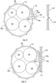
- the main body 102 is flexible and configured to be wrapped such that the main body 102 can circumscribe one or more discrete cables 130 ( see , e.g. , FIGS. 3 and 4 ).
- the main body 102 may be formed of a polymeric material.
- the main body 102 may comprise rubber, polypropylene, nylon 6,6, or acetal.
- the device 100 of the present invention comprises a securing feature 104.
- the securing feature 104 is attached to or is integral with the mounting portion 102b of the main body 102.
- the securing feature 104 may be configured to be secured to a mounting structure 150 ( see , e.g ., FIGS. 3 and 4 ).
- the securing feature 104 may be configured to be secured to a telecommunications tower or monopole.
- the securing feature 104 may comprise two barbs 104a separated by a cavity 120.
- the cavity 120 is configured to cooperate with a rib 108 when holding or bundling together one or more discrete cables 130 ( see , e.g ., FIGS. 3-5 ).
- the thickness ( T 2 ) of the mounting portion 102b of the main body 102 may be greater than the thickness ( T 1 ) of the wrapping portion 102a of the main body 102.
- the thickness ( T 2 ) of the mounting portion 102b of the main body 102 may be in a range of 0.15 inches to about 0.5 inches and the thickness ( T 1 ) of the wrapping portion 102a of the main body 102 may be in a range of about 0.062 inches to about 0.25 inches.
- Having a greater thickness ( T 2 ) of the mounting portion 102b of the main body 102 may help to increase the structural strength of the device 100 and provide a more solid formation to the device 100 when the device 100 is secured to a mounting structure 150 ( see , e.g ., FIGS. 3 and 4 ).
- the device 100 of the present invention comprises a plurality of apertures 106 spaced apart along the longitudinal axis ( A ) of the wrapping portion 102a of the main body 102.
- Each aperture 106 is spaced apart a distance ( L A ).
- the distance ( L A ) between each aperture 106 is in the range of about 1 inch to about 2 inches.
- the securing feature 104 may be configured to be received through one of the apertures 106 when the main body 102 of the device 100 is wrapped around one or more discrete cables 130 ( e.g ., bundling together a plurality of cables 130 ).
- each aperture 106 may be sized such that the securing feature 104 may be inserted through a respective aperture 106.
- each aperture 106 may have a diameter ( D ) in the range of about 0.5 inches to about 1 inch (nominally, about 0.75 inches).
- each aperture 106 comprises a rib 108 that extends across the respective aperture 106.
- Each rib 108 may be aligned perpendicular or parallel to the longitudinal axis ( A ) of the main body 102.
- the ribs 108 are aligned perpendicular to the longitudinal axis ( A ).
- each rib 108 is configured to cooperate with the securing feature 104 when the device 100 is holding one or more discrete cables 130 and optionally when the device 100 is being secured to a mounting structure 150 ( see , e.g. , FIG. 3 ) to provide additional stability.
- each rib 108 may have a thickness ( T R ) in the range of about 0.25 inches to about 0.5 inches and a width ( W R ) in the range of about 0.15 inches to about 0.45 inches. In some embodiments, the thickness ( T R ) and width ( W R ) of each rib 108 correspond to the depth ( D C ) and width ( W C ), respectively, of the cavity 120 of the securing feature 104 ( see , e.g ., FIG. 4 ).
- the main body 102 of the device 100 may comprise a plurality of stabilizing members (or feet) 112 (see , e.g. , FIGS. 1-4 ).
- the stabilizing members 112 may extend radially outwardly from one side of the wrapping portion 102a of the main body 102.
- the stabilizing members 112 may improve stability of the device 100 by helping to limit or prevent the device 100 from rocking/swaying after the securing feature 104 is inserted through an aperture 106 and the device 100 is secured to a mounting structure 150 ( see , e.g. , FIGS. 3 and 4 ).
- the device 100 of the present invention is adapted for holding one or more discrete cables 130 and securing the one or more cables 130 to a mounting structure 150.
- the main body 102 of the device 100 has sufficient flexibility to be wrapped around a plurality of discrete cables 130.
- the one or more discrete cables 130 comprise fiber optic cables, hybrid fiber/power cables and/or coaxial cables.
- the rib 108 within the aperture 106 cooperates with the securing feature 104 (e.g ., the cavity 120 between the barbs 104a and the shoulders 105 of each barb 104a ) ( see also , e.g. , FIG. 5 ) to hold the main body 102 of the device 100 circumscribed around the one or more cables 130.
- the device 100 in combination with a bundle of cables 130, may be secured to a mounting structure 150 by further inserting the securing feature 104 into a pre-configured aperture 152 in the mounting structure 150.
- the aperture 152 in the mounting structure 150 may be configured to receive the barbs 104a of the securing feature 104, thereby securing the device 100 (and the bundle of cables 130 ) to the mounting structure 150.
- the securing feature 104 is configured to be secured in an aperture 152 in the mounting structure 150 having a diameter ( D MS ) in the range of about 0.5 inches to about 1 inch (nominally, about 0.75 inches).
- each rib 108 may be aligned either perpendicular or parallel to the longitudinal axis ( A ) of the main body 102.
- the orientation of each rib 108 within an aperture 106 may correspond with the orientation of the securing feature 104. This allows the ribs 108 to cooperate with the securing feature 104 when holding or bundling together one or more discrete cables 130 and/or securing the device 100 to a mounting structure 150.
- the securing feature 104 comprises two barbs 104a
- the orientation of each rib 108 is perpendicular to the longitudinal axis ( A ) of the main body 102
- the orientation of the two barbs 104a should be parallel to the longitudinal axis ( A ) of the main body 102.
- This orientation allows the ribs 108 to properly align with the cavity 120 between the barbs 104a of the securing feature 104.
- the barbs 104a may each comprise a shoulder 105 that is configured to engage the rib 108 when the rib 108 is within the cavity 120 ( see also , e.g ., FIG. 5 ).
- each rib 108 is parallel to the longitudinal axis ( A ) of the main body 102, then the orientation of the two barbs 104a should be rotated 90 degrees relative to the longitudinal axis ( A ) of the main body 102 ( i.e ., perpendicular).
- the ribs 108 in cooperation with the cavity 120 (and shoulders 105 ) of the securing feature 104, may provide support to help prevent the securing feature 104 from snapping in and/or out of the aperture 152 in the mounting structure 150.
- the ribs 108 may comprise a plurality of protrusions 114.
- the protrusions 114 may be staggered along the length of each rib 108 ( see also , e.g ., FIG. 1 ).
- the protrusions 114 may provide added support to the rib 108 when the rib 108 is secured in the cavity 120 of the securing feature 104.
- the protrusions 114 may provide additional support to the barbs 104a to help prevent the securing feature 104 from snapping in and/or out of the aperture 152 in the mounting structure 150.
- the device 100 of the present invention may comprise at least one grippingtab 110 ( see , e.g ., FIG. 1 ).
- the at least one gripping tab 110 may be attached to or integral with the main body 102.
- the at least one gripping tab 110 may reside at an end of the main body 102 opposite to the securing feature 104 ( i.e ., opposite to the mounting portion 102b of the main body 102 ).
- the gripping tab(s) 110 provides the technician a place to hold the device 100 when wrapping the device 100 around the cable(s) 130.
- the gripping tab(s) 110 may help to reduce grip slippage during use of the device 100.
- the device 200 is similar to the device 100 shown above, except the device 200 may further comprise one or more conforming members 216.
- the one or more conforming members 216 may reside along the "inside" of the wrapping portion 102a of the main body 102 of the device 200.
- the conforming members 216 may be configured to further secure or "cushion" the one or more discrete cables 130 when the cable(s) 130 are circumscribed by the main body 102.
- the conforming members 216 may be in a variety of different shapes and sizes.
- the conforming members 216 have a polygonal or arced shape, and/or may be hollow ( see , e.g. , FIGS. 6 and 7 ) or solid.
- the conforming members 216 may comprise a separate unitary member. In some embodiments, the conforming members 216 may comprise a molded soft polymer material. The molded polymer material may be pliable and/or soft such that the conforming member(s) 216 may mold or "conform" to the one or more cables 130 as the device 200 is wrapped around the cable(s) 130.
- the conforming members 216 may comprise a silicone, a silicone gel or a thermoplastic elastomer.
- the conforming members 216 may take up “slack” and/or provide a "cushion” for the cable(s) 130 in the main body 102 that may result due to the spacing (or periods) ( L A ) between the plurality of apertures 106 when the device 200 is wrapped around one or more cables 130. For example, during wrapping of the device 200, inserting the securing feature 104 through one aperture 106 may result in the device 200 being too loose around the cable(s) 130, whereas inserting the securing feature 104 through the next aperture 106 may result in the device being too tight around the cable(s) 130.
- the conforming members 216 may assist in taking up (reducing) the "slack” in the device 200 and/or provide additional support ("cushion") to the cable(s) 130 from differences in tightness of the device 200 from aperture 106 to aperture 106.
- FIG. 8 which corresponds to an embodiment not covered by the claims, a device 300 adapted for holding one or more discrete cables is shown therein.
- the device 300 is similar to the devices 100, 200 shown above, except that the device 300 comprises an alternative securing feature 304 and the main body 102 of the device 300 comprises a frangible portion 102c.
- the securing feature 304 may comprise a threaded post 304a and a capture member 304b.
- the threaded post 304a may be configured to be received through one of the plurality of apertures 106 when the main body 102 of the device 300 is wrapped around the one or more discrete cables 130.
- the threaded post 304a is configured to be received through an aperture 106 having a diameter ( D ) in the range of about 0.5 inches to about 1 inch (nominally, about 0.75 inches).
- the capture member 304b may be configured to be secured ( e.g ., threaded or snapped) onto to the threaded post 304a.
- the main body 102 of the device 300 may comprise a frangible portion 102c.
- the frangible portion 102c may attach the capture member 304b to the device 300.
- the frangible portion 102c is configured to break away from the main body 102 such that the capture member 304b may be detached from the main body 102 of the device 300, thereby allowing the capture member 304b to be secured onto the threaded post 304a.
- the threaded post 304a may be a threaded bolt and the capture member 304b may be a breakaway nut ( see , e.g. , FIG. 8 ).
- a capture member 304b' may comprise an interior ridge 305 ( see , e.g ., FIG. 9 ).
- the ridge 305 may be configured to interlock with at least one thread of the post 304a.
- the capture member 304b' may be pushed onto the threaded post 304a until the ridge 305 interlocks with at least one of the threads of the post 304a.
- Other securing features 304 may be used as an alternative to the breakaway nut 304b, 304b', such as, for example, an elastic band or a retaining ring.
- the post 304a may have annular, rather than helical, threads, particularly when used with a capture member 304b' having a ridge 305.
- a securing feature 104 comprising a threaded bolt 304a and breakaway nut 304b may help to mitigate the stress that is applied on the securing feature 304 when the main body 102 of the device 300 circumscribes the cables 130.
- the additional retaining capability may reduce the chances of the securing feature 304 failing while the device is holding one or more cables 130.
- the device 400 is similar to the device 100 described herein in that the device 400 comprises a flexible main body 402, a securing feature 404, and a plurality of apertures 406.
- the main body 402 is flexible and configured to be wrapped such that the main body 402 can circumscribe one or more discrete cables 130.
- the main body 402 of the device 400 may comprise a wrapping portion 402a and a mounting portion 402b.
- the main body 402 may be formed of a polymeric material.
- the main body 402 may comprise rubber, polypropylene, nylon 6,6, or acetal.
- the securing feature 404 of device 400 may be attached to or integral with the mounting portion 402b of the main body 402.
- the securing feature 404 may be configured to be secured to a mounting structure 150.
- the securing feature 404 may be configured to be secured to a telecommunications tower, cable hanger adapter, or monopole.
- the securing feature 404 may comprise two barbs 404a separated by a cavity 420. Each barb 404a is configured to be received by a respective aperture 406 in the wrapping portion 402a of the main body 402 of the device 400. In some embodiments, the barbs 404a may each comprise a shoulder 405 that may further define the cavity 120.
- the cavity 420 is configured to receive a section (or "rib") 408 of the main body 402 located between each aperture 406.
- a section (or "rib") 408 of the main body 402 located between each aperture 406.
- the barbs 404a i.e ., the securing feature 404
- the barbs 404a may then be secured to a mounting structure 150, thereby securing the rib 408 within the cavity 420.
- the device 400 may comprise a plurality of undulations 407. Similar to the stabilizing members 112 described herein, the undulations 407 may improve stability of the device 400 by helping to limit or prevent the device 400 from rocking/swaying after the securing feature 404 is inserted through an aperture 406 and the device 400 is secured to a mounting structure 150. In addition, the undulation 407 may contribute to the flexibility of the device 400 to help the wrapping portion 402a to circumscribe one or more discrete cables 130.
- the device 400 may further comprise a plug 410 coupled to or integral with the mounting portion 402b of the main body 402.
- the plug 410 is sized and configured to be inserted into the cavity 420.
- the plug 410 is coupled to or integral with the mounting portion 402b via a flex member 403.
- the flex member 403 is configured such that the plug 410 may be inserted into the cavity 420 of the securing feature 404 while remaining coupled to the mounting portion 402b of the device 400.
- the plug 410 may comprise a protrusion 410a. As shown in FIG.
- the protrusion 410a may be sized and configured such that when the plug 410 is inserted into the cavity 420 of the securing feature 404, the protrusion 410a extends between the shoulders 405 of the barbs 404a, thereby providing additional support to the barbs 404a to help prevent the securing feature 404 from snapping in and/or out of an aperture 152 in the mounting structure 150.
- the device 400 may further comprise two guide hooks 412 adjacent to the free end of the wrapping portion 402a of the main body 402.
- the guide hooks 412 may be used to manage excess of the wrapping portion 402a when the device 400 is wrapped to circumscribe the cable(s) 130. For example, once wrapped around one or more discrete cables 130 (e.g ., bundling together a plurality of cables 130 ), the installer may hook the remaining wrapping portion 402a of the device 400 onto itself using the two guide hooks 412.
- a method for holding one or more discrete cables is provided according to claim 10.
- the method may further comprise inserting the securing feature through an aperture in the mounting structure, thereby securing the device and the one or more cables to the mounting structure.
Landscapes
- Engineering & Computer Science (AREA)
- Architecture (AREA)
- Civil Engineering (AREA)
- Structural Engineering (AREA)
- General Engineering & Computer Science (AREA)
- Mechanical Engineering (AREA)
- Installation Of Indoor Wiring (AREA)
- Clamps And Clips (AREA)
Claims (11)
- Vorrichtung (100) zum Halten von Kabeln in Kombination mit einem oder mehreren separaten Kabeln (130),
wobei die Vorrichtung umfasst:einen flexiblen Hauptkörper (102), der aus einem Polymermaterial, das eine Länge, eine Breite, eine Dicke und eine Längsachse aufweist, gebildet ist, wobei der Hauptkörper einen Wickelabschnitt (102a) und einen Befestigungsabschnitt (102b) umfasst, wobei der Wickelabschnitt konfiguriert ist, derart gewickelt zu werden, dass der Hauptkörper das eine oder die mehreren separaten Kabel umschreibt;ein Befestigungselement (104), das an dem Befestigungsabschnitt des Hauptkörpers befestigt oder damit einstückig gebildet und konfiguriert ist, an einer Befestigungsstruktur (150) befestigt zu werden; undmehrere Öffnungen (106) entlang der Längsachse des Wickelabschnitts des Hauptkörpers, wobei jede Öffnung angepasst ist, das Befestigungselement aufzunehmen,wobei der Hauptkörper um das eine oder die mehreren separaten Kabel gewickelt ist und das Befestigungselement durch mindestens eine der mehreren Öffnungen aufgenommen ist und dadurch das eine oder die mehreren separaten Kabel gehalten werden,dadurch gekennzeichnet, dass: jede Öffnung eine Rippe (108) umfasst, die sich über die Öffnung hinweg erstreckt, wobei die Rippe konfiguriert ist, mit dem Befestigungselement zusammenzuwirken, wenn ein oder mehrere separate Kabel gehalten werden, und optional die Vorrichtung an der Befestigungsstruktur befestigt. - Vorrichtung nach Anspruch 1, wobei jede Rippe senkrecht zur Längsachse des Hauptkörpers ist.
- Vorrichtung nach einem der vorstehenden Ansprüche, wobei das Befestigungselement zwei Widerhaken umfasst, die durch einen Hohlraum getrennt sind, und der Hohlraum konfiguriert ist, beim Befestigen der Vorrichtung an der Befestigungsstruktur mit einer entsprechenden Rippe zusammenzuwirken.
- Vorrichtung nach einem der vorstehenden Ansprüche, ferner umfassend ein Stöpselelement, das konfiguriert ist, in das Befestigungselement eingeführt zu werden, wenn das eine oder die mehreren separaten Kabel gehalten werden.
- Vorrichtung nach einem der vorstehenden Ansprüche, ferner umfassend mehrere Wellungen zwischen dem Befestigungsabschnitt und dem Wickelabschnitt der Vorrichtung.
- Vorrichtung nach einem der vorstehenden Ansprüche, wobei jede Rippe mehrere Vorsprünge umfasst, die konfiguriert sind, in das Befestigungselement einzugreifen.
- Vorrichtung nach einem der vorstehenden Ansprüche, wobei die Vorrichtung ferner ein oder mehrere konforme Elemente entlang der Länge einer Unterseite des Wickelabschnitts des Hauptkörpers umfasst und das eine oder die mehreren konformen Elemente konfiguriert sind, das eine oder die mehreren separaten Kabel weitergehend zu befestigen, wenn das eine oder die mehreren Kabel von dem Hauptkörper umschrieben sind.
- Vorrichtung nach einem der vorstehenden Ansprüche, wobei das Polymermaterial Gummi, Polypropylen oder Nylon umfasst.
- Vorrichtung nach einem der vorstehenden Ansprüche, wobei das eine oder die mehreren separaten Kabel Kabel umfassen, die ausgewählt sind aus einer Gruppe bestehend aus Lichtwellenleiterkabeln, Hybridfaser-/Stromkabeln und/oder Koaxialkabeln.
- Verfahren zum Halten von einem oder mehreren separaten Kabeln, wobei das Verfahren umfasst:
Bereitstellen einer Vorrichtung (100), die zum Halten von einem oder mehreren separaten Kabeln (130) angepasst ist, wobei die Vorrichtung umfasst:einen flexiblen Hauptkörper (102), der aus einem Polymermaterial, das eine Länge, eine Breite, eine Dicke und eine Längsachse aufweist, gebildet ist, wobei der Hauptkörper einen Wickelabschnitt (102a) und einen Befestigungsabschnitt (102b) umfasst, wobei der Wickelabschnitt konfiguriert ist, derart gewickelt zu werden, dass der Hauptkörper das eine oder die mehreren separaten Kabel umschreibt;ein Befestigungselement (104), das an dem Befestigungsabschnitt des Hauptkörpers befestigt oder damit einstückig gebildet und konfiguriert ist, an einer Befestigungsstruktur (150) befestigt zu werden; undmehrere Öffnungen (106) entlang der Längsachse des Wickelabschnitts des Hauptkörpers, wobei jede Öffnung eine Rippe umfasst, die sich über die Öffnung hinweg erstreckt,wobei das Befestigungselement konfiguriert ist, durch eine der mehreren Öffnungen aufgenommen zu werden, wenn der Hauptkörper um das eine oder die mehreren separaten Kabel gewickelt wird;Wickeln des Wickelabschnitts des Hauptkörpers der Vorrichtung um das eine oder die mehreren separaten Kabel; undEinführen des Befestigungselements durch mindestens eine der Öffnungen, sodass die Rippe, die sich über die Öffnung hinweg erstreckt, mit dem Befestigungselement zusammenwirkt und dadurch das eine oder die mehreren separaten Kabel gehalten werden. - Verfahren nach Anspruch 10, ferner umfassend: Einführen des Befestigungselements durch eine Öffnung in der Befestigungsstruktur und dadurch Befestigen der Vorrichtung und des einen oder der mehreren Kabel an der Befestigungsstruktur.
Applications Claiming Priority (1)
| Application Number | Priority Date | Filing Date | Title |
|---|---|---|---|
| US16/814,472 US11271378B2 (en) | 2018-12-28 | 2020-03-10 | Devices and methods for holding cables |
Publications (3)
| Publication Number | Publication Date |
|---|---|
| EP3879649A1 EP3879649A1 (de) | 2021-09-15 |
| EP3879649B1 true EP3879649B1 (de) | 2024-05-01 |
| EP3879649B8 EP3879649B8 (de) | 2024-05-29 |
Family
ID=74873489
Family Applications (1)
| Application Number | Title | Priority Date | Filing Date |
|---|---|---|---|
| EP21161676.8A Active EP3879649B8 (de) | 2020-03-10 | 2021-03-10 | Vorrichtungen und verfahren zum halten von kabeln |
Country Status (2)
| Country | Link |
|---|---|
| EP (1) | EP3879649B8 (de) |
| CN (1) | CN113381348A (de) |
Family Cites Families (9)
| Publication number | Priority date | Publication date | Assignee | Title |
|---|---|---|---|---|
| US4342438A (en) * | 1979-07-20 | 1982-08-03 | Illinois Tool Works Inc. | Flexible strap with integral attachment means |
| US4673150A (en) * | 1984-10-22 | 1987-06-16 | Mechanical Plastics Corp. | Plastic fasteners |
| US6443403B1 (en) * | 2000-09-11 | 2002-09-03 | Panduit Corp. | Cable routing clamp and method of application |
| US6533226B2 (en) * | 2000-09-14 | 2003-03-18 | Hellermanntyton Corporation | Saddle mount |
| CN101997284A (zh) * | 2009-08-20 | 2011-03-30 | 鸿富锦精密工业(深圳)有限公司 | 固定束线带 |
| US9306380B2 (en) | 2013-08-13 | 2016-04-05 | Commscope Technologies Llc | Grommet for cable hanger |
| EP4170839A1 (de) | 2015-03-27 | 2023-04-26 | CommScope Technologies LLC | Aufhänger zur montage von kabeln |
| US9903510B2 (en) | 2015-11-03 | 2018-02-27 | Commscope Technologies Llc | Hanger for mounting cables |
| US11268635B2 (en) * | 2018-12-28 | 2022-03-08 | Commscope Technologies Llc | Devices and methods for holding cables |
-
2021
- 2021-03-10 CN CN202110259147.2A patent/CN113381348A/zh active Pending
- 2021-03-10 EP EP21161676.8A patent/EP3879649B8/de active Active
Also Published As
| Publication number | Publication date |
|---|---|
| EP3879649A1 (de) | 2021-09-15 |
| CN113381348A (zh) | 2021-09-10 |
| EP3879649B8 (de) | 2024-05-29 |
Similar Documents
| Publication | Publication Date | Title |
|---|---|---|
| US11268635B2 (en) | Devices and methods for holding cables | |
| US11588309B2 (en) | Devices and methods for holding cables | |
| US11821550B2 (en) | Insert for mounting multiple cables in cable hanger | |
| CA2274276C (en) | Cable retainer of plastics for vehicles | |
| EP3033814B1 (de) | Öse für kabelaufhängung | |
| EP3827492B1 (de) | Vorrichtung und verfahren zum führen und schützen von mindestens einem stromkabel in einem solarpaneelmontagesystem | |
| US20220390042A1 (en) | Conduit management device | |
| EP3549213A1 (de) | Aufhänger zur montage mehrerer kabel | |
| US20210360878A1 (en) | Vine inhibiting cone and method of use thereof | |
| WO2009037450A2 (en) | A cable duct restraining device | |
| EP3879649A1 (de) | Vorrichtungen und verfahren zum halten von kabeln | |
| US11735900B2 (en) | Cable retention device, system and method | |
| WO2017220952A1 (en) | Ground stabilising device | |
| US12062899B2 (en) | Bundling suspension wire | |
| US20230021924A1 (en) | Radial clamp devices for clamping hoisting grips to cables | |
| JP5336211B2 (ja) | 架空ケーブル防護管 | |
| JP3558758B2 (ja) | 光ファイバケーブルの牽引具 | |
| KR20220146269A (ko) | 직경 가변형 콜게이트 튜브 | |
| CN218278469U (zh) | 一种防鼠罩 | |
| US20250244549A1 (en) | Cable support devices | |
| WO2020023461A1 (en) | Hanger assembly for mounting multiple cables | |
| WO2025174305A1 (en) | Device and method for attaching cables to a solar cell panel | |
| WO2020035647A1 (en) | Protector for a flexible elongate article | |
| JPH1138296A (ja) | 通信用多条布設光ファイバケーブル引上管端部用キャップ装置 | |
| JPH0671797U (ja) | 支線ガード |
Legal Events
| Date | Code | Title | Description |
|---|---|---|---|
| PUAI | Public reference made under article 153(3) epc to a published international application that has entered the european phase |
Free format text: ORIGINAL CODE: 0009012 |
|
| STAA | Information on the status of an ep patent application or granted ep patent |
Free format text: STATUS: REQUEST FOR EXAMINATION WAS MADE |
|
| 17P | Request for examination filed |
Effective date: 20210310 |
|
| AK | Designated contracting states |
Kind code of ref document: A1 Designated state(s): AL AT BE BG CH CY CZ DE DK EE ES FI FR GB GR HR HU IE IS IT LI LT LU LV MC MK MT NL NO PL PT RO RS SE SI SK SM TR |
|
| GRAP | Despatch of communication of intention to grant a patent |
Free format text: ORIGINAL CODE: EPIDOSNIGR1 |
|
| STAA | Information on the status of an ep patent application or granted ep patent |
Free format text: STATUS: GRANT OF PATENT IS INTENDED |
|
| RIC1 | Information provided on ipc code assigned before grant |
Ipc: B65D 63/10 20060101ALN20230918BHEP Ipc: F16B 2/22 20060101ALN20230918BHEP Ipc: F16B 2/20 20060101ALN20230918BHEP Ipc: F16L 3/23 20060101ALN20230918BHEP Ipc: F16L 3/14 20060101ALN20230918BHEP Ipc: F16L 3/137 20060101ALN20230918BHEP Ipc: F16L 3/133 20060101ALN20230918BHEP Ipc: F16L 3/12 20060101ALI20230918BHEP Ipc: H02G 3/32 20060101AFI20230918BHEP |
|
| INTG | Intention to grant announced |
Effective date: 20231010 |
|
| GRAS | Grant fee paid |
Free format text: ORIGINAL CODE: EPIDOSNIGR3 |
|
| GRAA | (expected) grant |
Free format text: ORIGINAL CODE: 0009210 |
|
| STAA | Information on the status of an ep patent application or granted ep patent |
Free format text: STATUS: THE PATENT HAS BEEN GRANTED |
|
| AK | Designated contracting states |
Kind code of ref document: B1 Designated state(s): AL AT BE BG CH CY CZ DE DK EE ES FI FR GB GR HR HU IE IS IT LI LT LU LV MC MK MT NL NO PL PT RO RS SE SI SK SM TR |
|
| REG | Reference to a national code |
Ref country code: GB Ref legal event code: FG4D |
|
| REG | Reference to a national code |
Ref country code: DE Ref legal event code: R081 Ref document number: 602021012469 Country of ref document: DE Owner name: OUTDOOR WIRELESS NETWORKS LLC (N.D.GES.D.STAAT, US Free format text: FORMER OWNER: COMMSCOPE TECHNOLOGIES LLC, HICKORY, NC, US Ref country code: DE Ref legal event code: R081 Ref document number: 602021012469 Country of ref document: DE Owner name: COMMSCOPE TECHNOLOGIES LLC, CLAREMONT, US Free format text: FORMER OWNER: COMMSCOPE TECHNOLOGIES LLC, HICKORY, NC, US |
|
| REG | Reference to a national code |
Ref country code: CH Ref legal event code: PK Free format text: BERICHTIGUNG B8 Ref country code: CH Ref legal event code: EP |
|
| RAP4 | Party data changed (patent owner data changed or rights of a patent transferred) |
Owner name: COMMSCOPE TECHNOLOGIES LLC |
|
| REG | Reference to a national code |
Ref country code: IE Ref legal event code: FG4D |
|
| RIN2 | Information on inventor provided after grant (corrected) |
Inventor name: STOCKMAN, CHRISTOPHER Inventor name: JOSHI, AVIRAL Inventor name: VACCARO, RONALD A. |
|
| REG | Reference to a national code |
Ref country code: DE Ref legal event code: R096 Ref document number: 602021012469 Country of ref document: DE |
|
| P01 | Opt-out of the competence of the unified patent court (upc) registered |
Effective date: 20240525 |
|
| REG | Reference to a national code |
Ref country code: LT Ref legal event code: MG9D |
|
| RAP2 | Party data changed (patent owner data changed or rights of a patent transferred) |
Owner name: OUTDOOR WIRELESS NETWORKS LLC |
|
| REG | Reference to a national code |
Ref country code: NL Ref legal event code: MP Effective date: 20240501 |
|
| REG | Reference to a national code |
Ref country code: GB Ref legal event code: 732E Free format text: REGISTERED BETWEEN 20240815 AND 20240821 |
|
| PG25 | Lapsed in a contracting state [announced via postgrant information from national office to epo] |
Ref country code: IS Free format text: LAPSE BECAUSE OF FAILURE TO SUBMIT A TRANSLATION OF THE DESCRIPTION OR TO PAY THE FEE WITHIN THE PRESCRIBED TIME-LIMIT Effective date: 20240901 |
|
| PG25 | Lapsed in a contracting state [announced via postgrant information from national office to epo] |
Ref country code: BG Free format text: LAPSE BECAUSE OF FAILURE TO SUBMIT A TRANSLATION OF THE DESCRIPTION OR TO PAY THE FEE WITHIN THE PRESCRIBED TIME-LIMIT Effective date: 20240501 |
|
| PG25 | Lapsed in a contracting state [announced via postgrant information from national office to epo] |
Ref country code: FI Free format text: LAPSE BECAUSE OF FAILURE TO SUBMIT A TRANSLATION OF THE DESCRIPTION OR TO PAY THE FEE WITHIN THE PRESCRIBED TIME-LIMIT Effective date: 20240501 Ref country code: HR Free format text: LAPSE BECAUSE OF FAILURE TO SUBMIT A TRANSLATION OF THE DESCRIPTION OR TO PAY THE FEE WITHIN THE PRESCRIBED TIME-LIMIT Effective date: 20240501 |
|
| PG25 | Lapsed in a contracting state [announced via postgrant information from national office to epo] |
Ref country code: GR Free format text: LAPSE BECAUSE OF FAILURE TO SUBMIT A TRANSLATION OF THE DESCRIPTION OR TO PAY THE FEE WITHIN THE PRESCRIBED TIME-LIMIT Effective date: 20240802 |
|
| PG25 | Lapsed in a contracting state [announced via postgrant information from national office to epo] |
Ref country code: PT Free format text: LAPSE BECAUSE OF FAILURE TO SUBMIT A TRANSLATION OF THE DESCRIPTION OR TO PAY THE FEE WITHIN THE PRESCRIBED TIME-LIMIT Effective date: 20240902 |
|
| REG | Reference to a national code |
Ref country code: AT Ref legal event code: MK05 Ref document number: 1683731 Country of ref document: AT Kind code of ref document: T Effective date: 20240501 |
|
| PG25 | Lapsed in a contracting state [announced via postgrant information from national office to epo] |
Ref country code: NL Free format text: LAPSE BECAUSE OF FAILURE TO SUBMIT A TRANSLATION OF THE DESCRIPTION OR TO PAY THE FEE WITHIN THE PRESCRIBED TIME-LIMIT Effective date: 20240501 |
|
| PG25 | Lapsed in a contracting state [announced via postgrant information from national office to epo] |
Ref country code: ES Free format text: LAPSE BECAUSE OF FAILURE TO SUBMIT A TRANSLATION OF THE DESCRIPTION OR TO PAY THE FEE WITHIN THE PRESCRIBED TIME-LIMIT Effective date: 20240501 |
|
| PG25 | Lapsed in a contracting state [announced via postgrant information from national office to epo] |
Ref country code: AT Free format text: LAPSE BECAUSE OF FAILURE TO SUBMIT A TRANSLATION OF THE DESCRIPTION OR TO PAY THE FEE WITHIN THE PRESCRIBED TIME-LIMIT Effective date: 20240501 |
|
| REG | Reference to a national code |
Ref country code: DE Ref legal event code: R081 Ref document number: 602021012469 Country of ref document: DE Owner name: OUTDOOR WIRELESS NETWORKS LLC (N.D.GES.D.STAAT, US Free format text: FORMER OWNER: COMMSCOPE TECHNOLOGIES LLC, CLAREMONT, NC, US |
|
| PG25 | Lapsed in a contracting state [announced via postgrant information from national office to epo] |
Ref country code: PL Free format text: LAPSE BECAUSE OF FAILURE TO SUBMIT A TRANSLATION OF THE DESCRIPTION OR TO PAY THE FEE WITHIN THE PRESCRIBED TIME-LIMIT Effective date: 20240501 |
|
| PG25 | Lapsed in a contracting state [announced via postgrant information from national office to epo] |
Ref country code: LV Free format text: LAPSE BECAUSE OF FAILURE TO SUBMIT A TRANSLATION OF THE DESCRIPTION OR TO PAY THE FEE WITHIN THE PRESCRIBED TIME-LIMIT Effective date: 20240501 |
|
| PG25 | Lapsed in a contracting state [announced via postgrant information from national office to epo] |
Ref country code: PT Free format text: LAPSE BECAUSE OF FAILURE TO SUBMIT A TRANSLATION OF THE DESCRIPTION OR TO PAY THE FEE WITHIN THE PRESCRIBED TIME-LIMIT Effective date: 20240902 Ref country code: PL Free format text: LAPSE BECAUSE OF FAILURE TO SUBMIT A TRANSLATION OF THE DESCRIPTION OR TO PAY THE FEE WITHIN THE PRESCRIBED TIME-LIMIT Effective date: 20240501 Ref country code: NO Free format text: LAPSE BECAUSE OF FAILURE TO SUBMIT A TRANSLATION OF THE DESCRIPTION OR TO PAY THE FEE WITHIN THE PRESCRIBED TIME-LIMIT Effective date: 20240801 Ref country code: NL Free format text: LAPSE BECAUSE OF FAILURE TO SUBMIT A TRANSLATION OF THE DESCRIPTION OR TO PAY THE FEE WITHIN THE PRESCRIBED TIME-LIMIT Effective date: 20240501 Ref country code: LV Free format text: LAPSE BECAUSE OF FAILURE TO SUBMIT A TRANSLATION OF THE DESCRIPTION OR TO PAY THE FEE WITHIN THE PRESCRIBED TIME-LIMIT Effective date: 20240501 Ref country code: IS Free format text: LAPSE BECAUSE OF FAILURE TO SUBMIT A TRANSLATION OF THE DESCRIPTION OR TO PAY THE FEE WITHIN THE PRESCRIBED TIME-LIMIT Effective date: 20240901 Ref country code: HR Free format text: LAPSE BECAUSE OF FAILURE TO SUBMIT A TRANSLATION OF THE DESCRIPTION OR TO PAY THE FEE WITHIN THE PRESCRIBED TIME-LIMIT Effective date: 20240501 Ref country code: GR Free format text: LAPSE BECAUSE OF FAILURE TO SUBMIT A TRANSLATION OF THE DESCRIPTION OR TO PAY THE FEE WITHIN THE PRESCRIBED TIME-LIMIT Effective date: 20240802 Ref country code: FI Free format text: LAPSE BECAUSE OF FAILURE TO SUBMIT A TRANSLATION OF THE DESCRIPTION OR TO PAY THE FEE WITHIN THE PRESCRIBED TIME-LIMIT Effective date: 20240501 Ref country code: ES Free format text: LAPSE BECAUSE OF FAILURE TO SUBMIT A TRANSLATION OF THE DESCRIPTION OR TO PAY THE FEE WITHIN THE PRESCRIBED TIME-LIMIT Effective date: 20240501 Ref country code: BG Free format text: LAPSE BECAUSE OF FAILURE TO SUBMIT A TRANSLATION OF THE DESCRIPTION OR TO PAY THE FEE WITHIN THE PRESCRIBED TIME-LIMIT Effective date: 20240501 Ref country code: AT Free format text: LAPSE BECAUSE OF FAILURE TO SUBMIT A TRANSLATION OF THE DESCRIPTION OR TO PAY THE FEE WITHIN THE PRESCRIBED TIME-LIMIT Effective date: 20240501 Ref country code: RS Free format text: LAPSE BECAUSE OF FAILURE TO SUBMIT A TRANSLATION OF THE DESCRIPTION OR TO PAY THE FEE WITHIN THE PRESCRIBED TIME-LIMIT Effective date: 20240801 |
|
| PG25 | Lapsed in a contracting state [announced via postgrant information from national office to epo] |
Ref country code: DK Free format text: LAPSE BECAUSE OF FAILURE TO SUBMIT A TRANSLATION OF THE DESCRIPTION OR TO PAY THE FEE WITHIN THE PRESCRIBED TIME-LIMIT Effective date: 20240501 |
|
| PG25 | Lapsed in a contracting state [announced via postgrant information from national office to epo] |
Ref country code: EE Free format text: LAPSE BECAUSE OF FAILURE TO SUBMIT A TRANSLATION OF THE DESCRIPTION OR TO PAY THE FEE WITHIN THE PRESCRIBED TIME-LIMIT Effective date: 20240501 |
|
| PG25 | Lapsed in a contracting state [announced via postgrant information from national office to epo] |
Ref country code: CZ Free format text: LAPSE BECAUSE OF FAILURE TO SUBMIT A TRANSLATION OF THE DESCRIPTION OR TO PAY THE FEE WITHIN THE PRESCRIBED TIME-LIMIT Effective date: 20240501 |
|
| PG25 | Lapsed in a contracting state [announced via postgrant information from national office to epo] |
Ref country code: SK Free format text: LAPSE BECAUSE OF FAILURE TO SUBMIT A TRANSLATION OF THE DESCRIPTION OR TO PAY THE FEE WITHIN THE PRESCRIBED TIME-LIMIT Effective date: 20240501 Ref country code: RO Free format text: LAPSE BECAUSE OF FAILURE TO SUBMIT A TRANSLATION OF THE DESCRIPTION OR TO PAY THE FEE WITHIN THE PRESCRIBED TIME-LIMIT Effective date: 20240501 |
|
| PG25 | Lapsed in a contracting state [announced via postgrant information from national office to epo] |
Ref country code: SM Free format text: LAPSE BECAUSE OF FAILURE TO SUBMIT A TRANSLATION OF THE DESCRIPTION OR TO PAY THE FEE WITHIN THE PRESCRIBED TIME-LIMIT Effective date: 20240501 |
|
| PG25 | Lapsed in a contracting state [announced via postgrant information from national office to epo] |
Ref country code: SM Free format text: LAPSE BECAUSE OF FAILURE TO SUBMIT A TRANSLATION OF THE DESCRIPTION OR TO PAY THE FEE WITHIN THE PRESCRIBED TIME-LIMIT Effective date: 20240501 Ref country code: SK Free format text: LAPSE BECAUSE OF FAILURE TO SUBMIT A TRANSLATION OF THE DESCRIPTION OR TO PAY THE FEE WITHIN THE PRESCRIBED TIME-LIMIT Effective date: 20240501 Ref country code: RO Free format text: LAPSE BECAUSE OF FAILURE TO SUBMIT A TRANSLATION OF THE DESCRIPTION OR TO PAY THE FEE WITHIN THE PRESCRIBED TIME-LIMIT Effective date: 20240501 Ref country code: EE Free format text: LAPSE BECAUSE OF FAILURE TO SUBMIT A TRANSLATION OF THE DESCRIPTION OR TO PAY THE FEE WITHIN THE PRESCRIBED TIME-LIMIT Effective date: 20240501 Ref country code: DK Free format text: LAPSE BECAUSE OF FAILURE TO SUBMIT A TRANSLATION OF THE DESCRIPTION OR TO PAY THE FEE WITHIN THE PRESCRIBED TIME-LIMIT Effective date: 20240501 Ref country code: CZ Free format text: LAPSE BECAUSE OF FAILURE TO SUBMIT A TRANSLATION OF THE DESCRIPTION OR TO PAY THE FEE WITHIN THE PRESCRIBED TIME-LIMIT Effective date: 20240501 |
|
| REG | Reference to a national code |
Ref country code: DE Ref legal event code: R097 Ref document number: 602021012469 Country of ref document: DE |
|
| PG25 | Lapsed in a contracting state [announced via postgrant information from national office to epo] |
Ref country code: IT Free format text: LAPSE BECAUSE OF FAILURE TO SUBMIT A TRANSLATION OF THE DESCRIPTION OR TO PAY THE FEE WITHIN THE PRESCRIBED TIME-LIMIT Effective date: 20240501 |
|
| PLBE | No opposition filed within time limit |
Free format text: ORIGINAL CODE: 0009261 |
|
| STAA | Information on the status of an ep patent application or granted ep patent |
Free format text: STATUS: NO OPPOSITION FILED WITHIN TIME LIMIT |
|
| 26N | No opposition filed |
Effective date: 20250204 |
|
| PG25 | Lapsed in a contracting state [announced via postgrant information from national office to epo] |
Ref country code: SI Free format text: LAPSE BECAUSE OF FAILURE TO SUBMIT A TRANSLATION OF THE DESCRIPTION OR TO PAY THE FEE WITHIN THE PRESCRIBED TIME-LIMIT Effective date: 20240501 |
|
| PG25 | Lapsed in a contracting state [announced via postgrant information from national office to epo] |
Ref country code: SE Free format text: LAPSE BECAUSE OF FAILURE TO SUBMIT A TRANSLATION OF THE DESCRIPTION OR TO PAY THE FEE WITHIN THE PRESCRIBED TIME-LIMIT Effective date: 20240501 |
|
| PG25 | Lapsed in a contracting state [announced via postgrant information from national office to epo] |
Ref country code: MC Free format text: LAPSE BECAUSE OF FAILURE TO SUBMIT A TRANSLATION OF THE DESCRIPTION OR TO PAY THE FEE WITHIN THE PRESCRIBED TIME-LIMIT Effective date: 20240501 |
|
| REG | Reference to a national code |
Ref country code: CH Ref legal event code: H13 Free format text: ST27 STATUS EVENT CODE: U-0-0-H10-H13 (AS PROVIDED BY THE NATIONAL OFFICE) Effective date: 20251023 |
|
| PG25 | Lapsed in a contracting state [announced via postgrant information from national office to epo] |
Ref country code: LU Free format text: LAPSE BECAUSE OF NON-PAYMENT OF DUE FEES Effective date: 20250310 |
|
| REG | Reference to a national code |
Ref country code: BE Ref legal event code: MM Effective date: 20250331 |
|
| PG25 | Lapsed in a contracting state [announced via postgrant information from national office to epo] |
Ref country code: BE Free format text: LAPSE BECAUSE OF NON-PAYMENT OF DUE FEES Effective date: 20250331 |
|
| PG25 | Lapsed in a contracting state [announced via postgrant information from national office to epo] |
Ref country code: CH Free format text: LAPSE BECAUSE OF NON-PAYMENT OF DUE FEES Effective date: 20250331 |
|
| PG25 | Lapsed in a contracting state [announced via postgrant information from national office to epo] |
Ref country code: IE Free format text: LAPSE BECAUSE OF NON-PAYMENT OF DUE FEES Effective date: 20250310 |
|
| PGFP | Annual fee paid to national office [announced via postgrant information from national office to epo] |
Ref country code: GB Payment date: 20260327 Year of fee payment: 6 |
|
| PGFP | Annual fee paid to national office [announced via postgrant information from national office to epo] |
Ref country code: DE Payment date: 20260327 Year of fee payment: 6 |
|
| PGFP | Annual fee paid to national office [announced via postgrant information from national office to epo] |
Ref country code: FR Payment date: 20260325 Year of fee payment: 6 |