EP3880923B1 - Système de guidage pour le guidage d'un battant de porte monté de manière mobile - Google Patents
Système de guidage pour le guidage d'un battant de porte monté de manière mobile Download PDFInfo
- Publication number
- EP3880923B1 EP3880923B1 EP19797160.9A EP19797160A EP3880923B1 EP 3880923 B1 EP3880923 B1 EP 3880923B1 EP 19797160 A EP19797160 A EP 19797160A EP 3880923 B1 EP3880923 B1 EP 3880923B1
- Authority
- EP
- European Patent Office
- Prior art keywords
- guide rail
- guide
- door wing
- guide system
- furniture
- Prior art date
- Legal status (The legal status is an assumption and is not a legal conclusion. Google has not performed a legal analysis and makes no representation as to the accuracy of the status listed.)
- Active
Links
Images




Classifications
-
- E—FIXED CONSTRUCTIONS
- E05—LOCKS; KEYS; WINDOW OR DOOR FITTINGS; SAFES
- E05D—HINGES OR SUSPENSION DEVICES FOR DOORS, WINDOWS OR WINGS
- E05D15/00—Suspension arrangements for wings
- E05D15/26—Suspension arrangements for wings for folding wings
- E05D15/264—Suspension arrangements for wings for folding wings for bi-fold wings
-
- E—FIXED CONSTRUCTIONS
- E05—LOCKS; KEYS; WINDOW OR DOOR FITTINGS; SAFES
- E05D—HINGES OR SUSPENSION DEVICES FOR DOORS, WINDOWS OR WINGS
- E05D15/00—Suspension arrangements for wings
- E05D15/56—Suspension arrangements for wings with successive different movements
- E05D15/58—Suspension arrangements for wings with successive different movements with both swinging and sliding movements
-
- E—FIXED CONSTRUCTIONS
- E06—DOORS, WINDOWS, SHUTTERS, OR ROLLER BLINDS IN GENERAL; LADDERS
- E06B—FIXED OR MOVABLE CLOSURES FOR OPENINGS IN BUILDINGS, VEHICLES, FENCES OR LIKE ENCLOSURES IN GENERAL, e.g. DOORS, WINDOWS, BLINDS, GATES
- E06B3/00—Window sashes, door leaves, or like elements for closing wall or like openings; Layout of fixed or moving closures, e.g. windows in wall or like openings; Features of rigidly-mounted outer frames relating to the mounting of wing frames
- E06B3/32—Arrangements of wings characterised by the manner of movement; Arrangements of movable wings in openings; Features of wings or frames relating solely to the manner of movement of the wing
- E06B3/50—Arrangements of wings characterised by the manner of movement; Arrangements of movable wings in openings; Features of wings or frames relating solely to the manner of movement of the wing with more than one kind of movement
- E06B3/5045—Arrangements of wings characterised by the manner of movement; Arrangements of movable wings in openings; Features of wings or frames relating solely to the manner of movement of the wing with more than one kind of movement specially adapted for furniture
-
- E—FIXED CONSTRUCTIONS
- E05—LOCKS; KEYS; WINDOW OR DOOR FITTINGS; SAFES
- E05D—HINGES OR SUSPENSION DEVICES FOR DOORS, WINDOWS OR WINGS
- E05D15/00—Suspension arrangements for wings
- E05D15/56—Suspension arrangements for wings with successive different movements
- E05D15/58—Suspension arrangements for wings with successive different movements with both swinging and sliding movements
- E05D2015/586—Suspension arrangements for wings with successive different movements with both swinging and sliding movements with travelling hinge parts
-
- E—FIXED CONSTRUCTIONS
- E05—LOCKS; KEYS; WINDOW OR DOOR FITTINGS; SAFES
- E05F—DEVICES FOR MOVING WINGS INTO OPEN OR CLOSED POSITION; CHECKS FOR WINGS; WING FITTINGS NOT OTHERWISE PROVIDED FOR, CONCERNED WITH THE FUNCTIONING OF THE WING
- E05F1/00—Closers or openers for wings, not otherwise provided for in this subclass
- E05F1/08—Closers or openers for wings, not otherwise provided for in this subclass spring-actuated, e.g. for horizontally sliding wings
- E05F1/16—Closers or openers for wings, not otherwise provided for in this subclass spring-actuated, e.g. for horizontally sliding wings for sliding wings
-
- E—FIXED CONSTRUCTIONS
- E05—LOCKS; KEYS; WINDOW OR DOOR FITTINGS; SAFES
- E05Y—INDEXING SCHEME ASSOCIATED WITH SUBCLASSES E05D AND E05F, RELATING TO CONSTRUCTION ELEMENTS, ELECTRIC CONTROL, POWER SUPPLY, POWER SIGNAL OR TRANSMISSION, USER INTERFACES, MOUNTING OR COUPLING, DETAILS, ACCESSORIES, AUXILIARY OPERATIONS NOT OTHERWISE PROVIDED FOR, APPLICATION THEREOF
- E05Y2201/00—Constructional elements; Accessories therefor
- E05Y2201/20—Brakes; Disengaging means; Holders; Stops; Valves; Accessories therefor
- E05Y2201/21—Brakes
- E05Y2201/212—Buffers
-
- E—FIXED CONSTRUCTIONS
- E05—LOCKS; KEYS; WINDOW OR DOOR FITTINGS; SAFES
- E05Y—INDEXING SCHEME ASSOCIATED WITH SUBCLASSES E05D AND E05F, RELATING TO CONSTRUCTION ELEMENTS, ELECTRIC CONTROL, POWER SUPPLY, POWER SIGNAL OR TRANSMISSION, USER INTERFACES, MOUNTING OR COUPLING, DETAILS, ACCESSORIES, AUXILIARY OPERATIONS NOT OTHERWISE PROVIDED FOR, APPLICATION THEREOF
- E05Y2201/00—Constructional elements; Accessories therefor
- E05Y2201/20—Brakes; Disengaging means; Holders; Stops; Valves; Accessories therefor
- E05Y2201/224—Stops
-
- E—FIXED CONSTRUCTIONS
- E05—LOCKS; KEYS; WINDOW OR DOOR FITTINGS; SAFES
- E05Y—INDEXING SCHEME ASSOCIATED WITH SUBCLASSES E05D AND E05F, RELATING TO CONSTRUCTION ELEMENTS, ELECTRIC CONTROL, POWER SUPPLY, POWER SIGNAL OR TRANSMISSION, USER INTERFACES, MOUNTING OR COUPLING, DETAILS, ACCESSORIES, AUXILIARY OPERATIONS NOT OTHERWISE PROVIDED FOR, APPLICATION THEREOF
- E05Y2201/00—Constructional elements; Accessories therefor
- E05Y2201/40—Motors; Magnets; Springs; Weights; Accessories therefor
- E05Y2201/404—Function thereof
- E05Y2201/422—Function thereof for opening
- E05Y2201/426—Function thereof for opening for the initial opening movement
-
- E—FIXED CONSTRUCTIONS
- E05—LOCKS; KEYS; WINDOW OR DOOR FITTINGS; SAFES
- E05Y—INDEXING SCHEME ASSOCIATED WITH SUBCLASSES E05D AND E05F, RELATING TO CONSTRUCTION ELEMENTS, ELECTRIC CONTROL, POWER SUPPLY, POWER SIGNAL OR TRANSMISSION, USER INTERFACES, MOUNTING OR COUPLING, DETAILS, ACCESSORIES, AUXILIARY OPERATIONS NOT OTHERWISE PROVIDED FOR, APPLICATION THEREOF
- E05Y2201/00—Constructional elements; Accessories therefor
- E05Y2201/60—Suspension or transmission members; Accessories therefor
- E05Y2201/622—Suspension or transmission members elements
- E05Y2201/696—Screw mechanisms
-
- E—FIXED CONSTRUCTIONS
- E05—LOCKS; KEYS; WINDOW OR DOOR FITTINGS; SAFES
- E05Y—INDEXING SCHEME ASSOCIATED WITH SUBCLASSES E05D AND E05F, RELATING TO CONSTRUCTION ELEMENTS, ELECTRIC CONTROL, POWER SUPPLY, POWER SIGNAL OR TRANSMISSION, USER INTERFACES, MOUNTING OR COUPLING, DETAILS, ACCESSORIES, AUXILIARY OPERATIONS NOT OTHERWISE PROVIDED FOR, APPLICATION THEREOF
- E05Y2600/00—Mounting or coupling arrangements for elements provided for in this subclass
- E05Y2600/10—Adjustable
- E05Y2600/12—Adjustable by manual operation
-
- E—FIXED CONSTRUCTIONS
- E05—LOCKS; KEYS; WINDOW OR DOOR FITTINGS; SAFES
- E05Y—INDEXING SCHEME ASSOCIATED WITH SUBCLASSES E05D AND E05F, RELATING TO CONSTRUCTION ELEMENTS, ELECTRIC CONTROL, POWER SUPPLY, POWER SIGNAL OR TRANSMISSION, USER INTERFACES, MOUNTING OR COUPLING, DETAILS, ACCESSORIES, AUXILIARY OPERATIONS NOT OTHERWISE PROVIDED FOR, APPLICATION THEREOF
- E05Y2600/00—Mounting or coupling arrangements for elements provided for in this subclass
- E05Y2600/10—Adjustable
- E05Y2600/30—Adjustment motion
- E05Y2600/31—Linear motion
- E05Y2600/312—Horizontal motion
-
- E—FIXED CONSTRUCTIONS
- E05—LOCKS; KEYS; WINDOW OR DOOR FITTINGS; SAFES
- E05Y—INDEXING SCHEME ASSOCIATED WITH SUBCLASSES E05D AND E05F, RELATING TO CONSTRUCTION ELEMENTS, ELECTRIC CONTROL, POWER SUPPLY, POWER SIGNAL OR TRANSMISSION, USER INTERFACES, MOUNTING OR COUPLING, DETAILS, ACCESSORIES, AUXILIARY OPERATIONS NOT OTHERWISE PROVIDED FOR, APPLICATION THEREOF
- E05Y2600/00—Mounting or coupling arrangements for elements provided for in this subclass
- E05Y2600/10—Adjustable
- E05Y2600/30—Adjustment motion
- E05Y2600/32—Rotary motion
- E05Y2600/322—Rotary motion around a horizontal axis
-
- E—FIXED CONSTRUCTIONS
- E05—LOCKS; KEYS; WINDOW OR DOOR FITTINGS; SAFES
- E05Y—INDEXING SCHEME ASSOCIATED WITH SUBCLASSES E05D AND E05F, RELATING TO CONSTRUCTION ELEMENTS, ELECTRIC CONTROL, POWER SUPPLY, POWER SIGNAL OR TRANSMISSION, USER INTERFACES, MOUNTING OR COUPLING, DETAILS, ACCESSORIES, AUXILIARY OPERATIONS NOT OTHERWISE PROVIDED FOR, APPLICATION THEREOF
- E05Y2900/00—Application of doors, windows, wings or fittings thereof
- E05Y2900/20—Application of doors, windows, wings or fittings thereof for furniture, e.g. cabinets
- E05Y2900/212—Doors disappearing in pockets in the furniture body
Definitions
- the invention relates to a piece of furniture with a furniture body and with at least one door leaf, which is mounted so as to be movable relative to the furniture body by a guide system of the type to be described.
- a furniture door is shown, which is pivotably mounted on a stop bar via hinges.
- the stop bar is movable along an upper and lower guide by a scissor mechanism, allowing the furniture door to be moved depthwise into the furniture body.
- the lower guide has an adjustable stop, allowing the furniture door to be adjusted laterally in the closed position.
- FIGS. 7a-7d show a guide system for door leaves with two guide rails extending at right angles to each other, wherein a support in the form of an elongated column is provided for the movable mounting of at least one door leaf.
- the support together with the two door leaves, is arranged in a depth direction of the furniture body. movable so that the door leaves can be retracted into a lateral slot in the furniture body in a parallel position when not in use.
- a guide rail is attached to the side wall of the furniture body, with the support being movable along the guide rail in the depth direction of the furniture body.
- the object of the present invention is to provide a guidance system of the type mentioned at the outset while avoiding the disadvantages discussed above.
- the at least one stop is adjustable in the longitudinal direction relative to the at least one guide rail by the at least one adjusting device.
- the at least one stop is adjustable for determining an end position of the carrier relative to the guide rail running in the depth direction in the assembly position, so that an end position of the carrier can be adjusted by actuating the adjusting device.
- the adjustment device can also be used to position the door leaf to be connected to the support in a depth direction of the furniture body in such a way that a front narrow side of the door leaf in the assembled state in the inserted The door leaf can be aligned flush with a narrow side of the furniture body.
- the adjustment of the at least one stop relative to the guide rail can, for example, be stepless.
- the adjustment device can have several predefined positions for adjustable positioning of the stop.
- the adjustment device can be designed to be self-locking. This ensures that a preset position of the stop relative to the guide rail remains in every set position.
- the adjustment device can have at least one rotatably mounted operating element, wherein the at least one stop can be adjusted relative to the guide rail by rotating the operating element.
- the guide rail can have a front end region in the installed position, with the operating element being arranged at the front end region of the guide rail.
- the operating element is immediately and directly accessible from the front, i.e., even when the door leaf is fully retracted in the depth direction, for adjustment manually or using a tool.
- the operating element can be arranged on a front end face of the guide rail in the installed position. This results in a simple, intuitive, and convenient adjustment of the stop relative to the guide rail.
- the operating element can be mounted so as to be rotatable about an axis which runs essentially parallel to the longitudinal axis of the guide rail.
- the guide rail may have at least one linear guide for displaceably supporting the stop, wherein the stop is displaceable in or along the at least one linear guide by actuating the adjusting device.
- the guide system can have a transmission mechanism that converts a rotary movement of the operating element into a linear movement of the stop. Converting a rotary movement into a linear movement is a measure known to those skilled in the art and can be achieved, for example, by a rack-and-pinion arrangement, a worm gear, or a threaded spindle-and-nut arrangement.
- the transmission mechanism also offers the possibility of changing the transmission ratio.
- the operating element can be driven by a cordless screwdriver at a relatively high speed, whereby the stop can be driven with a small stroke but with great force.
- the transmission mechanism can, for example, have at least one coupling rod connected to the at least one stop, wherein the coupling rod can be moved relative to the guide rail by actuating the adjustment device.
- the guide rail can have at least one guide channel for receiving the coupling rod, whereby the coupling rod can be arranged on the guide rail in a visually unobtrusive manner and securely against any possible interference with fingers or objects.
- the coupling rod can be designed either as a push lever or as a threaded spindle.
- the at least one stop is arranged on an ejector of an ejection device, by means of which the carrier can be ejected in a direction opposite to the depth direction by overpressing the stop into an overpressing position located behind the end position, wherein the ejection device as a whole can be adjusted relative to the guide rail by the adjusting device.
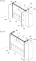
- Fig. 1a shows a perspective view of a piece of furniture 1 with a furniture body 2 and a folding-sliding door having movable door leaves 3a, 3b; 4a, 4b.
- the door leaves 3a, 3b and the door leaves 4a, 4b are each movably mounted by a guide system 5 between a first position, in which the door leaves 3a, 3b; 4a, 4b are aligned substantially coplanar to one another, and a second position, in which the door leaves 3a, 3b; 4a, 4b are aligned substantially parallel to one another.
- the guide system 5 comprises a longitudinal rail 7 with a longitudinal direction (L), wherein a carriage 6, which can be coupled to the second door leaf 3b, is mounted for movement along the longitudinal rail 7. In an installed position, the longitudinal rail 7 is arranged essentially horizontally and parallel to a front edge of the furniture body 2.
- Fig. 1b shows the furniture 1, where the door leaves 3a, 3b starting from the Fig. 1a shown coplanar position into an angular position to each other.
- the first door leaf 3a can be movably mounted on a support 11, for example, via two or more furniture hinges 10, wherein the support 11 can be inserted into the receiving compartment 8a in a depth direction (Z).
- the support 11 is in the figure shown in a transfer position, so that the carriage 6 can be moved between the Longitudinal rail 7 and the support 11 are transferable. In the transfer position shown, the support 11 is releasably locked to the longitudinal rail 7, wherein the locking between the longitudinal rail 7 and the support 11 can be released by the carriage 6 entering or onto the support 11.
- the support 11 is designed in the form of an elongated column, the length of which corresponds to at least half the height of the door leaves 3a, 3b.
- the two door leaves 3a, 3b are connected to one another in an articulated manner about a vertically extending axis via at least one hinge fitting 9.
- the second door leaf 3b is mounted so as to be movable along the longitudinal rail 7 via the carriage 6.
- Fig. 2a shows the furniture 1 with the door leaves 3a and 3b, which are now aligned parallel to each other.
- the support 11 has been unlocked by the carriage 6 entering the longitudinal rail 7, so that the support 11 (together with the carriage 6 and the door leaves 3a, 3b) can be moved in the depth direction (Z) along a guide rail 17 ( Fig. 3 ) of the guide system 5 can be inserted into the receiving compartment 8a.
- Fig. 2b shows the furniture 1 with the door leaves 3a, 3b, which are now in a fully inserted state in the receiving compartment 8a.
- the door leaves 3a, 3b are thus guided by the guide system 5 from a first position according to Fig. 1a , in which the door leaves 3a, 3b are aligned substantially coplanar to each other, and a second position according to Fig. 2b , in which the door leaves 3a, 3b are aligned essentially parallel to each other and can be accommodated within the receiving compartment 8a.
- a Figures 2a, 2b The kitchen 12 shown can be completely covered, so that the kitchen 12 can be visually separated from the remaining area of a living space.
- the receiving compartment 8a is formed by a side wall 13a and a fixed furniture part 13b spaced parallel to the side wall 13a, wherein the door leaves 3a, 3b can be inserted in a parallel position to one another between the side wall 13a and the fixed furniture part 13b.
- Fig. 3 shows a perspective view of the guide system 5 in the area between the side wall 13a and the fixed furniture part 13b, between which the receiving compartment 8a for receiving the door leaves 3a, 3b is formed.
- the longitudinal rail 7 has a longitudinal direction (L) which, in an assembled position, runs parallel to a front edge of the furniture body 2.
- a guide rail 17 with a longitudinal direction (L2) is arranged on the fixed furniture part 13b, wherein the longitudinal direction (L) of the longitudinal rail 7 and the longitudinal direction (L2) of the guide rail 17 run transversely, preferably substantially at right angles, to one another.
- the support 11 is designed for the movable mounting of the at least one door leaf 3a, wherein the door leaf 3a, in an assembled state, for example, via two or more furniture hinges 10 ( Fig. 1b ) is pivotally mounted on the support 11 about an axis extending vertically in the assembled position.
- the support 11 has at least one guide device 14, by means of which the support 11 can be moved along the guide rail 17 in the depth direction (Z) and in a direction opposite to the depth direction (Z).
- the guide device 14 of the support 11 has at least one roller 14a, which is movably mounted along a first track 17a of the guide rail 17.
- the support 11 can be releasably locked to the longitudinal rail 7 via a receiving device 15.
- the receiving device 15 is designed to receive the carriage 6, so that the carriage 6 can be moved into the receiving device 15 from the longitudinal rail 7.
- guide grooves 20, 21 can be formed in the longitudinal rail 7, which extend in the longitudinal direction (L) of the longitudinal rail 7 and which, in the transfer position of the receiving device 15, are aligned with corresponding guide grooves 20a, 21a of the receiving device 15. In this way, the rollers of the carriage 6 can be moved without an interfering abutting edge between the longitudinal rail 7 and the receiving device 15.
- the receiving device 15 has at least one support roller 16 which is separate from the guide device 14 of the carrier 11 and is movably mounted along the guide rail 17. It is preferably provided that the guide rail 17 has a first track 17a and at least one second track 17b which is separate from the first track 17a, wherein the track roller 14a of the guide device 14 is guided along the first track 17a of the Guide rail 17 and the at least one support roller 16 of the receiving device 15 are movably mounted along the second running web 17b of the guide rail 17.
- the carrier 11 and the receiving device 15 are connected to one another in a movement-coupled manner during a movement along the guide rail 17 in the depth direction (Z), wherein it is preferably provided that the receiving device 15 are coupled to one another without play during a movement along the guide rail 17 in the depth direction (Z) and in a direction opposite to the depth direction (Z).
- at least one further guide rail 18 can be provided, along which at least one further roller 19 of the carrier 11 is movably mounted.
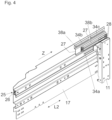
- Fig. 4 shows a perspective view of the guide rail 17 to be arranged on the fixed furniture part 13b and in the depth direction (Z) of the furniture body 2.
- An adjustment device 25 with a rotatably mounted operating element 26 is arranged on the front end of the guide rail 17.
- the stop 28 can be adjusted to define an end position of the support 11 relative to the guide rail 17.
- the stop 28 is arranged on an ejector 36 of an ejection device 27.
- the carrier 11 By pushing the stop 28 into an overpressure position arranged behind the end position, the carrier 11 can be ejected by the force of the ejection device 27 in a direction opposite to the depth direction (Z).
- Fig. 5 shows the guide system 5 in an exploded view.
- the guide rail 17 has a longitudinal direction (L2), wherein the at least one stop 28 is mounted displaceably in the longitudinal direction (L2) by actuating the adjusting device 25.
- the operating element 26 is arranged, which is rotatable on a bearing part 30 but immovable in the longitudinal direction (L2).
- the operating element 26 can have an undercut (for example in the form of a recess) in which the bearing part 30 can be received in a form-fitting manner.
- the bearing part 30 is to be fastened to the front end region of the guide rail 17 via a first screw 31.
- the operating element 26 is threadably engaged with a coupling rod 32 via a threaded portion 37, wherein the coupling rod 32 is movable in the longitudinal direction (L2) by actuating the operating element 26.
- the coupling rod 32 is connected via a second screw 33 to the ejection device 27, which is displaceably mounted in or along at least one linear guide 34a of the guide rail 17.
- the ejection device 27 enables the carrier 11 to be ejected in a direction opposite to the depth direction (Z).
- two stops 28 are provided, each arranged or formed on an ejector 36 of the ejection device 27.
- the ejectors 36 each comprise, in a known manner, a lockable energy accumulator, which can be unlocked by moving the stops 28 into an overpressure position arranged behind the end position.
- the ejection device 27 further comprises an insertion slot 29 for a part of the carrier 11, so that the position of the carrier 11 in the end position can be stabilized in a direction running transversely to the longitudinal direction (L2).
- the receiving device 15 of the carrier 11 can contact the stops 28 and move them into the overpressure position, so that the energy accumulators of the ejectors 36 can be unlocked and the carrier 11 can be ejected in a direction opposite to the depth direction (Z) by the force of these energy accumulators.
- Fig. 6a shows the guide system 5 in a side view, wherein the carrier 11 assumes a first end position relative to the guide rail 17.
- the at least one stop 28 is adjustable in the longitudinal direction (L2) of the guide rail 17 by the adjustment device 25.
- at least one or more linear guides 34a, 34b, 34c can be provided.
- the linear guide 34a is formed on the guide rail 17, while the two other linear guides 34b, 34c are arranged on the ejection device 27, wherein the linear guides 34b, 34c are displaceable by actuating the adjustment device 25 relative to pins 38a, 38b, which are mounted stationary relative to the guide rail 17.
- Fig. 6b shows the guide system 5 with the support 11 in a second end position deviating from the first end position.
- the stop 28 By adjusting the stop 28 to determine an end position of the support 11, manufacturing tolerances of the door leaves 3a, 3b or different widths of the door leaves 3a, 3b can be compensated, so that a front end of the door leaves 3a, 3b inserted into the receiving compartment 8a of the furniture body 2 ( Fig. 2b ) can be aligned flush relative to the front end faces of the side wall 13a and the fixed furniture part 13b.
- the at least one stop 28 can be adjusted by the adjustment device 25 between 0 mm and 50 mm, preferably between 0 mm and 130 mm.
Landscapes
- Engineering & Computer Science (AREA)
- Mechanical Engineering (AREA)
- Civil Engineering (AREA)
- Structural Engineering (AREA)
- Support Devices For Sliding Doors (AREA)
- Cabinets, Racks, Or The Like Of Rigid Construction (AREA)
- Extensible Doors And Revolving Doors (AREA)
Claims (15)
- Système de guidage (5) pour le guidage d'au moins un vantail de porte (3a) monté de manière mobile par rapport à un corps de meuble (2), en particulier d'une porte pliante-coulissante, comprenant:- au moins un rail de guidage (17) avec une direction longitudinale (L2), dans lequel la direction longitudinale (L2) du rail de guidage (17) s'étend dans un état de montage sur le corps de meuble (2) de manière sensiblement parallèle à une direction de profondeur (Z) du corps de meuble (2),- un support (11) destiné à monter de manière mobile l'au moins un vantail de porte (3a), dans lequel le support (11) est monté de manière à pouvoir être déplacé au moins par endroits le long du rail de guidage (17),- au moins une butée (28) pour déterminer une position finale de l'au moins un support (11) dans la direction longitudinale (L2) du rail de guidage (17), dans lequel l'au moins une butée (28) est disposée sur un éjecteur (36) d'un dispositif d'éjection (27) par lequel le support (11) peut être éjecté par surpression de la butée (28) dans une position de surpression se trouvant derrière la position finale dans une direction opposée à la direction de profondeur (Z)caractérisé en ce que
le système de guidage (5)- comprend au moins un dispositif de réglage (25) destiné à régler une position de l'au moins une butée (28),- et que l'au moins une butée (28) peut être réglée par l'au moins un dispositif de réglage (25) dans la direction longitudinale (L2) par rapport à l'au moins un rail de guidage (17),- dans lequel le dispositif d'éjection (27) peut être réglé dans son ensemble par le dispositif de réglage (25) par rapport au rail de guidage (17). - Système de guidage selon la revendication 1, caractérisé en ce que le dispositif de réglage (25) est réalisé de manière autobloquante.
- Système de guidage selon la revendication 1 ou 2, caractérisé en ce que le dispositif de réglage (25) présente au moins un élément de commande (26) monté de manière à pouvoir tourner, dans lequel l'au moins une butée (28) peut être réglée par rapport au rail de guidage (17) par une rotation de l'élément de commande (26).
- Système de guidage selon la revendication 3, caractérisé en ce que l'au moins un élément de commande (26) est disposé de manière fixe lors d'une rotation de l'élément de commande (26) dans la direction longitudinale (L2) du rail de guidage (17).
- Système de guidage selon la revendication 3 ou 4, caractérisé en ce que le rail de guidage (17) présente une zone d'extrémité avant en position de montage, dans lequel l'élément de commande (26) est disposé sur la zone d'extrémité avant du rail de guidage (17).
- Système de guidage selon l'une quelconque des revendications 3 à 5, caractérisé en ce que l'élément de commande (26) est disposé dans une position de montage sur une face frontale avant du rail de guidage (17).
- Système de guidage selon l'une quelconque des revendications 3 à 6, caractérisé en ce que l'élément de commande (26) est monté de manière à pouvoir tourner autour d'un axe qui est sensiblement parallèle à l'axe longitudinal (L2) du rail de guidage (17).
- Système de guidage selon l'une quelconque des revendications 3 à 7, caractérisé en ce qu'est prévu un mécanisme de transmission qui convertit un mouvement de rotation de l'élément de commande (26) en un mouvement linéaire de l'au moins une butée (28).
- Système de guidage selon la revendication 8, caractérisé en ce que le mécanisme de transmission présente au moins une tige d'accouplement (32) reliée à l'au moins une butée (28), dans lequel la tige d'accouplement (32) est mobile par un actionnement du dispositif de réglage (25) par rapport au rail de guidage (17).
- Système de guidage selon la revendication 9, caractérisé en ce que le rail de guidage (17) présente au moins un canal de guidage (35) s'étendant dans la direction longitudinale (L2) pour recevoir la tige d'accouplement (32).
- Système de guidage selon l'une quelconque des revendications 1 à 10, caractérisé en ce qu'au moins un guidage linéaire (34a, 34b, 34c) est prévu pour monté de manière coulissante l'au moins une butée (28).
- Système de guidage selon l'une quelconque des revendications 1 à 11, caractérisé en ce que le système de guidage (5) présente un rail longitudinal (7) qui, dans un état de montage, s'étend de manière transversale, de préférence de manière sensiblement perpendiculaire, au rail de guidage (17).
- Meuble (1) avec un corps de meuble (2) et avec au moins un vantail de porte (3a) monté de manière mobile par rapport au corps de meuble (2) et avec un système de guidage (5) selon l'une des revendications 1 à 12 pour guider le vantail de porte (3a) par rapport au corps de meuble (2).
- Meuble selon la revendication 13, caractérisé en ce que le rail de guidage (17) est disposé sur le corps de meuble (2) et s'étend dans une direction de profondeur (Z) du corps de meuble (2), dans lequel l'au moins un vantail de porte (3a) est relié de manière mobile au support (11) et est monté de manière mobile conjointement avec le support (11) le long du rail de guidage (17) dans la direction de profondeur (Z) du corps de meuble (2).
- Meuble selon la revendication 14, caractérisé en ce que le meuble (1) présente au moins un deuxième vantail de porte (3b) qui est relié de manière articulée au premier vantail de porte (3a), dans lequel le premier vantail de porte (3a) et le deuxième vantail de porte (3b) sont montés de manière mobile entre une première position, dans laquelle le premier vantail de porte (3a) et le deuxième vantail de porte (3b) sont orientés de manière sensiblement coplanaire l'un par rapport à l'autre, et une deuxième position, dans laquelle le premier vantail de porte (3a) et le deuxième vantail de porte (3b) sont orientés de manière sensiblement parallèle l'un par rapport à l'autre, dans lequel le premier vantail de porte (3a) et le deuxième vantail de porte (3b) sont montés de manière mobile à partir de la deuxième position conjointement avec le support (11) le long du rail de guidage (17) dans la direction de profondeur (Z) du corps de meuble (2).
Priority Applications (1)
| Application Number | Priority Date | Filing Date | Title |
|---|---|---|---|
| EP25172206.2A EP4567241A3 (fr) | 2018-11-14 | 2019-10-18 | Système de guidage pour guider un battant de porte monté de manière mobile |
Applications Claiming Priority (2)
| Application Number | Priority Date | Filing Date | Title |
|---|---|---|---|
| ATA50997/2018A AT521260B1 (de) | 2018-11-14 | 2018-11-14 | Führungssystem zur Führung eines bewegbar gelagerten Türflügels |
| PCT/AT2019/060350 WO2020097640A1 (fr) | 2018-11-14 | 2019-10-18 | Système de guidage pour le guidage d'un battant de porte monté de manière mobile |
Related Child Applications (1)
| Application Number | Title | Priority Date | Filing Date |
|---|---|---|---|
| EP25172206.2A Division EP4567241A3 (fr) | 2018-11-14 | 2019-10-18 | Système de guidage pour guider un battant de porte monté de manière mobile |
Publications (2)
| Publication Number | Publication Date |
|---|---|
| EP3880923A1 EP3880923A1 (fr) | 2021-09-22 |
| EP3880923B1 true EP3880923B1 (fr) | 2025-04-30 |
Family
ID=68424544
Family Applications (2)
| Application Number | Title | Priority Date | Filing Date |
|---|---|---|---|
| EP19797160.9A Active EP3880923B1 (fr) | 2018-11-14 | 2019-10-18 | Système de guidage pour le guidage d'un battant de porte monté de manière mobile |
| EP25172206.2A Pending EP4567241A3 (fr) | 2018-11-14 | 2019-10-18 | Système de guidage pour guider un battant de porte monté de manière mobile |
Family Applications After (1)
| Application Number | Title | Priority Date | Filing Date |
|---|---|---|---|
| EP25172206.2A Pending EP4567241A3 (fr) | 2018-11-14 | 2019-10-18 | Système de guidage pour guider un battant de porte monté de manière mobile |
Country Status (9)
| Country | Link |
|---|---|
| US (1) | US11952816B2 (fr) |
| EP (2) | EP3880923B1 (fr) |
| JP (1) | JP7130871B2 (fr) |
| CN (1) | CN113167089B (fr) |
| AT (1) | AT521260B1 (fr) |
| ES (1) | ES3033475T3 (fr) |
| MY (1) | MY209125A (fr) |
| TW (1) | TWI730471B (fr) |
| WO (1) | WO2020097640A1 (fr) |
Families Citing this family (12)
| Publication number | Priority date | Publication date | Assignee | Title |
|---|---|---|---|---|
| AT519479B1 (de) * | 2017-05-11 | 2018-07-15 | Blum Gmbh Julius | Führungssystem zur Führung eines Türflügels |
| AT519902B1 (de) * | 2017-05-11 | 2022-07-15 | Blum Gmbh Julius | Führungssystem zur Führung eines Türflügels |
| AT521139B1 (de) * | 2018-11-14 | 2019-11-15 | Blum Gmbh Julius | Führungssystem zur Führung eines bewegbar gelagerten Türflügels |
| AT523272B1 (de) * | 2019-12-19 | 2021-07-15 | Blum Gmbh Julius | Führungssystem zur Führung eines bewegbar gelagerten Türflügels |
| AT523327A1 (de) * | 2019-12-19 | 2021-07-15 | Blum Gmbh Julius | Führungsvorrichtung zur Führung eines Möbelteils |
| AT523270B1 (de) * | 2019-12-19 | 2021-07-15 | Blum Gmbh Julius | Anordnung zur Führung einer Schiebetür oder Falt-Schiebetür |
| AT523271B1 (de) | 2019-12-19 | 2021-07-15 | Blum Gmbh Julius | Führungsanordnung zur Führung wenigstens eines bewegbaren Möbelteils |
| AT523302B1 (de) | 2019-12-19 | 2023-05-15 | Blum Gmbh Julius | Anordnung mit einem Möbelscharnier und einer Abdeckung |
| CN111749583A (zh) * | 2020-06-15 | 2020-10-09 | 中山市欧派克五金制品有限公司 | 一种空间智动隔断系统 |
| AT524380A1 (de) * | 2020-10-22 | 2022-05-15 | Blum Gmbh Julius | Verfahren zum Bewegen wenigstens eines Türflügels |
| AT524557B1 (de) | 2020-12-17 | 2022-07-15 | Blum Gmbh Julius | Führungssystem zur Führung wenigstens eines Türflügels relativ zu einem Möbelkorpus |
| AT526130A1 (de) * | 2022-04-29 | 2023-11-15 | Blum Gmbh Julius | Anordnung zur Führung wenigstens eines bewegbaren Möbelteiles relativ zu einem Möbelkorpus |
Citations (1)
| Publication number | Priority date | Publication date | Assignee | Title |
|---|---|---|---|---|
| JPS5841893U (ja) * | 1981-09-14 | 1983-03-19 | 松下電工株式会社 | 家具の扉構造 |
Family Cites Families (26)
| Publication number | Priority date | Publication date | Assignee | Title |
|---|---|---|---|---|
| US4451284A (en) | 1981-07-28 | 1984-05-29 | Ciba-Geigy Corporation | Derivatives of 2-nitro-4- or -5-pyridyloxyphenylphosphonic acid, the preparation thereof, the use thereof as herbicides and/or plant growth regulators |
| CH670555A5 (fr) * | 1986-07-02 | 1989-06-30 | Karl Haab | |
| US4872287A (en) * | 1988-05-13 | 1989-10-10 | C. Hager & Sons Hinge Manufacturing Company | Latching mechanism for trolley-hung doors |
| KR100573463B1 (ko) * | 1997-06-24 | 2006-04-24 | 하바 아게 | 미닫이문과 안내장치의 연결장치 |
| IL137708A0 (en) * | 1999-03-16 | 2001-10-31 | Hawa Ag | Buffer device |
| JP2003074251A (ja) * | 2001-09-07 | 2003-03-12 | Yamaguchiyasushi Seisakusho:Kk | 仏間の正面開閉装置 |
| EP1813752A1 (fr) * | 2005-10-12 | 2007-08-01 | Caimi Export S.P.A. | Meuble aver des portes coulissantes parallelles et non coplanaires |
| US20070159037A1 (en) * | 2006-01-10 | 2007-07-12 | Knape & Vogt Manufacturing Company | Hinge bracket for a pocket door |
| JP4786477B2 (ja) * | 2006-09-05 | 2011-10-05 | アトムリビンテック株式会社 | 引戸装置 |
| DE102007022269B4 (de) * | 2007-05-09 | 2010-09-02 | Karl Simon Gmbh & Co. Kg | Möbelbeschlag |
| ES2323037B1 (es) * | 2007-10-25 | 2010-04-08 | Klein Iberica, S.A. | Mecanismo de regulacion para puertas correderas. |
| FR2928166B1 (fr) * | 2008-03-03 | 2013-08-23 | Edac | Dispositif de guidage pour porte coulissante escamotable |
| TWM362282U (en) * | 2009-01-09 | 2009-08-01 | Bing-Yan Chen | Window alignment lock |
| DE102011050394A1 (de) * | 2011-05-17 | 2012-11-22 | Hettich-Heinze Gmbh & Co. Kg | Beschlag für eine Schiebetür |
| US8402606B1 (en) * | 2011-10-18 | 2013-03-26 | Patrick Tsai | Door closer with buffer mechanism for a sliding door |
| RU2667137C2 (ru) * | 2014-01-23 | 2018-09-14 | Кобленц С.п.А. | Стопорное и демпфирующее устройство для узлов каретки раздвижных дверей для зданий или мебели и подобных им |
| EP2977534B1 (fr) * | 2014-07-22 | 2020-04-15 | Eclisse S.R.L. | Rail, en particulier pour des cadres encastrées de portes coulissantes |
| AT516282B1 (de) * | 2014-11-26 | 2016-04-15 | Blum Gmbh Julius | Anordnung zum Aufspreizen wenigstens zweier gelenkig miteinander verbundener Türflügel |
| DE102015106781A1 (de) * | 2015-04-30 | 2016-11-03 | Hettich-Oni Gmbh & Co. Kg | Ausstoßvorrichtung für ein bewegbares Möbelteil |
| AT16159U1 (de) * | 2015-06-09 | 2019-02-15 | Blum Gmbh Julius | Ausstoßvorrichtung für ein bewegbares Möbelteil |
| WO2017123908A1 (fr) * | 2016-01-14 | 2017-07-20 | Pemko Manufacturing Company, Inc. | Dispositif et système d'arrêt en douceur |
| AT519246B1 (de) * | 2017-01-13 | 2018-05-15 | Blum Gmbh Julius | Führungssystem zur Führung eines bewegbar gelagerten Möbelteiles |
| AT519247B1 (de) * | 2017-01-13 | 2018-05-15 | Blum Gmbh Julius | Führungssystem zur Führung zumindest eines bewegbar gelagerten Türflügels |
| AT519374B1 (de) | 2017-01-13 | 2018-06-15 | Blum Gmbh Julius | Führungssystem zur Führung eines bewegbar gelagerten Möbelteiles |
| AT519513B1 (de) * | 2017-01-13 | 2022-09-15 | Blum Gmbh Julius | Anordnung zur Führung einer Schiebetür oder Falt-Schiebetür an einer Möbelwand |
| KR102592617B1 (ko) * | 2018-02-13 | 2023-10-23 | 테르노 스코레볼리 에스.피.에이. 유니페르소날레 | 문과 옷장 문을 슬라이딩으로 움직이기 위한 장치 |
-
2018
- 2018-11-14 AT ATA50997/2018A patent/AT521260B1/de active
-
2019
- 2019-10-18 EP EP19797160.9A patent/EP3880923B1/fr active Active
- 2019-10-18 ES ES19797160T patent/ES3033475T3/es active Active
- 2019-10-18 JP JP2021526377A patent/JP7130871B2/ja active Active
- 2019-10-18 MY MYPI2021002303A patent/MY209125A/en unknown
- 2019-10-18 WO PCT/AT2019/060350 patent/WO2020097640A1/fr not_active Ceased
- 2019-10-18 EP EP25172206.2A patent/EP4567241A3/fr active Pending
- 2019-10-18 CN CN201980074750.4A patent/CN113167089B/zh active Active
- 2019-10-25 TW TW108138556A patent/TWI730471B/zh active
-
2021
- 2021-04-30 US US17/245,283 patent/US11952816B2/en active Active
Patent Citations (1)
| Publication number | Priority date | Publication date | Assignee | Title |
|---|---|---|---|---|
| JPS5841893U (ja) * | 1981-09-14 | 1983-03-19 | 松下電工株式会社 | 家具の扉構造 |
Also Published As
| Publication number | Publication date |
|---|---|
| ES3033475T3 (en) | 2025-08-04 |
| CN113167089A (zh) | 2021-07-23 |
| EP4567241A3 (fr) | 2025-08-27 |
| MY209125A (en) | 2025-06-23 |
| US11952816B2 (en) | 2024-04-09 |
| EP4567241A2 (fr) | 2025-06-11 |
| US20210246700A1 (en) | 2021-08-12 |
| TW202037804A (zh) | 2020-10-16 |
| EP3880923A1 (fr) | 2021-09-22 |
| JP2022507445A (ja) | 2022-01-18 |
| TWI730471B (zh) | 2021-06-11 |
| JP7130871B2 (ja) | 2022-09-05 |
| AT521260A4 (de) | 2019-12-15 |
| AT521260B1 (de) | 2019-12-15 |
| CN113167089B (zh) | 2022-12-23 |
| WO2020097640A1 (fr) | 2020-05-22 |
Similar Documents
| Publication | Publication Date | Title |
|---|---|---|
| EP3880923B1 (fr) | Système de guidage pour le guidage d'un battant de porte monté de manière mobile | |
| EP3475508B1 (fr) | Ferrure de meuble | |
| EP3899177B1 (fr) | Système de guidage pour guider au moins un battant de porte monté de manière mobile | |
| EP3969703B1 (fr) | Système de guidage pour guider au moins un battant de porte | |
| EP1959792B1 (fr) | Meuble presentant au moins des premiere et deuxieme parties de meuble | |
| EP1151697B1 (fr) | Dispositif pour régler l'inclinaison d'un panneau frontal d'un tiroir | |
| EP3622154A1 (fr) | Système de guidage pour le guidage d'un battant de porte | |
| AT521139A4 (de) | Führungssystem zur Führung eines bewegbar gelagerten Türflügels | |
| EP3880917B1 (fr) | Charnière de meuble | |
| EP3491966A1 (fr) | Dispositif de raccordement et meuble ou appareil électroménager | |
| DE102007029557B4 (de) | Führungsvorrichtung für einen Schiebeflügel | |
| EP0941889A2 (fr) | Dispositif d'extraction | |
| EP2281963B1 (fr) | Paroi de séparation mobile | |
| EP4048122B1 (fr) | Combinaison d'un element de mouvement et d'un element de synchronisation pour des rails de tiroir | |
| EP3880918B1 (fr) | Charnière de meuble | |
| EP4419771B1 (fr) | Dispositif de guidage d'au moins deux portes de meubles | |
| EP4263993B1 (fr) | Ensemble de guidage d'une partie de meuble mobile | |
| EP3344835B1 (fr) | Charnière et revêtement muni d'une charnière | |
| WO2025056287A1 (fr) | Ferrure de porte coulissante et agencement de porte coulissante associé | |
| AT518048B1 (de) | Schubladenwand | |
| AT523789B1 (de) | Ausziehführung für ein bewegbares Möbelteil | |
| DE19717806A1 (de) | Mitnehmer für einen Seilzugfensterheber | |
| EP3945936B1 (fr) | Dispositif de chargement ou d'éjection | |
| EP2618698B1 (fr) | Dispositif de réglage de l'inclinaison d'une partie de meuble mobile, et meuble correspondant | |
| AT526953B1 (de) | Führungsanordnung zur Führung eines bewegbaren Möbelteils |
Legal Events
| Date | Code | Title | Description |
|---|---|---|---|
| STAA | Information on the status of an ep patent application or granted ep patent |
Free format text: STATUS: UNKNOWN |
|
| STAA | Information on the status of an ep patent application or granted ep patent |
Free format text: STATUS: THE INTERNATIONAL PUBLICATION HAS BEEN MADE |
|
| PUAI | Public reference made under article 153(3) epc to a published international application that has entered the european phase |
Free format text: ORIGINAL CODE: 0009012 |
|
| STAA | Information on the status of an ep patent application or granted ep patent |
Free format text: STATUS: REQUEST FOR EXAMINATION WAS MADE |
|
| 17P | Request for examination filed |
Effective date: 20210426 |
|
| AK | Designated contracting states |
Kind code of ref document: A1 Designated state(s): AL AT BE BG CH CY CZ DE DK EE ES FI FR GB GR HR HU IE IS IT LI LT LU LV MC MK MT NL NO PL PT RO RS SE SI SK SM TR |
|
| DAV | Request for validation of the european patent (deleted) | ||
| DAX | Request for extension of the european patent (deleted) | ||
| P01 | Opt-out of the competence of the unified patent court (upc) registered |
Effective date: 20230523 |
|
| STAA | Information on the status of an ep patent application or granted ep patent |
Free format text: STATUS: EXAMINATION IS IN PROGRESS |
|
| 17Q | First examination report despatched |
Effective date: 20240607 |
|
| GRAP | Despatch of communication of intention to grant a patent |
Free format text: ORIGINAL CODE: EPIDOSNIGR1 |
|
| STAA | Information on the status of an ep patent application or granted ep patent |
Free format text: STATUS: GRANT OF PATENT IS INTENDED |
|
| GRAS | Grant fee paid |
Free format text: ORIGINAL CODE: EPIDOSNIGR3 |
|
| INTG | Intention to grant announced |
Effective date: 20250225 |
|
| GRAA | (expected) grant |
Free format text: ORIGINAL CODE: 0009210 |
|
| STAA | Information on the status of an ep patent application or granted ep patent |
Free format text: STATUS: THE PATENT HAS BEEN GRANTED |
|
| AK | Designated contracting states |
Kind code of ref document: B1 Designated state(s): AL AT BE BG CH CY CZ DE DK EE ES FI FR GB GR HR HU IE IS IT LI LT LU LV MC MK MT NL NO PL PT RO RS SE SI SK SM TR |
|
| REG | Reference to a national code |
Ref country code: CH Ref legal event code: EP Ref country code: GB Ref legal event code: FG4D Free format text: NOT ENGLISH |
|
| REG | Reference to a national code |
Ref country code: IE Ref legal event code: FG4D Free format text: LANGUAGE OF EP DOCUMENT: GERMAN |
|
| REG | Reference to a national code |
Ref country code: DE Ref legal event code: R096 Ref document number: 502019013299 Country of ref document: DE |
|
| REG | Reference to a national code |
Ref country code: ES Ref legal event code: FG2A Ref document number: 3033475 Country of ref document: ES Kind code of ref document: T3 Effective date: 20250804 |
|
| REG | Reference to a national code |
Ref country code: NL Ref legal event code: MP Effective date: 20250430 |
|
| PG25 | Lapsed in a contracting state [announced via postgrant information from national office to epo] |
Ref country code: PT Free format text: LAPSE BECAUSE OF FAILURE TO SUBMIT A TRANSLATION OF THE DESCRIPTION OR TO PAY THE FEE WITHIN THE PRESCRIBED TIME-LIMIT Effective date: 20250901 Ref country code: FI Free format text: LAPSE BECAUSE OF FAILURE TO SUBMIT A TRANSLATION OF THE DESCRIPTION OR TO PAY THE FEE WITHIN THE PRESCRIBED TIME-LIMIT Effective date: 20250430 |
|
| REG | Reference to a national code |
Ref country code: LT Ref legal event code: MG9D |
|
| PG25 | Lapsed in a contracting state [announced via postgrant information from national office to epo] |
Ref country code: NO Free format text: LAPSE BECAUSE OF FAILURE TO SUBMIT A TRANSLATION OF THE DESCRIPTION OR TO PAY THE FEE WITHIN THE PRESCRIBED TIME-LIMIT Effective date: 20250730 Ref country code: GR Free format text: LAPSE BECAUSE OF FAILURE TO SUBMIT A TRANSLATION OF THE DESCRIPTION OR TO PAY THE FEE WITHIN THE PRESCRIBED TIME-LIMIT Effective date: 20250731 |
|
| PG25 | Lapsed in a contracting state [announced via postgrant information from national office to epo] |
Ref country code: PL Free format text: LAPSE BECAUSE OF FAILURE TO SUBMIT A TRANSLATION OF THE DESCRIPTION OR TO PAY THE FEE WITHIN THE PRESCRIBED TIME-LIMIT Effective date: 20250430 Ref country code: NL Free format text: LAPSE BECAUSE OF FAILURE TO SUBMIT A TRANSLATION OF THE DESCRIPTION OR TO PAY THE FEE WITHIN THE PRESCRIBED TIME-LIMIT Effective date: 20250430 |
|
| PGFP | Annual fee paid to national office [announced via postgrant information from national office to epo] |
Ref country code: TR Payment date: 20250930 Year of fee payment: 7 |
|
| PG25 | Lapsed in a contracting state [announced via postgrant information from national office to epo] |
Ref country code: BG Free format text: LAPSE BECAUSE OF FAILURE TO SUBMIT A TRANSLATION OF THE DESCRIPTION OR TO PAY THE FEE WITHIN THE PRESCRIBED TIME-LIMIT Effective date: 20250430 |
|
| PG25 | Lapsed in a contracting state [announced via postgrant information from national office to epo] |
Ref country code: HR Free format text: LAPSE BECAUSE OF FAILURE TO SUBMIT A TRANSLATION OF THE DESCRIPTION OR TO PAY THE FEE WITHIN THE PRESCRIBED TIME-LIMIT Effective date: 20250430 |
|
| PG25 | Lapsed in a contracting state [announced via postgrant information from national office to epo] |
Ref country code: RS Free format text: LAPSE BECAUSE OF FAILURE TO SUBMIT A TRANSLATION OF THE DESCRIPTION OR TO PAY THE FEE WITHIN THE PRESCRIBED TIME-LIMIT Effective date: 20250731 |
|
| PG25 | Lapsed in a contracting state [announced via postgrant information from national office to epo] |
Ref country code: IS Free format text: LAPSE BECAUSE OF FAILURE TO SUBMIT A TRANSLATION OF THE DESCRIPTION OR TO PAY THE FEE WITHIN THE PRESCRIBED TIME-LIMIT Effective date: 20250830 |
|
| PG25 | Lapsed in a contracting state [announced via postgrant information from national office to epo] |
Ref country code: LV Free format text: LAPSE BECAUSE OF FAILURE TO SUBMIT A TRANSLATION OF THE DESCRIPTION OR TO PAY THE FEE WITHIN THE PRESCRIBED TIME-LIMIT Effective date: 20250430 |
|
| REG | Reference to a national code |
Ref country code: CH Ref legal event code: U11 Free format text: ST27 STATUS EVENT CODE: U-0-0-U10-U11 (AS PROVIDED BY THE NATIONAL OFFICE) Effective date: 20251101 |
|
| PGFP | Annual fee paid to national office [announced via postgrant information from national office to epo] |
Ref country code: DE Payment date: 20251028 Year of fee payment: 7 |
|
| PG25 | Lapsed in a contracting state [announced via postgrant information from national office to epo] |
Ref country code: DK Free format text: LAPSE BECAUSE OF FAILURE TO SUBMIT A TRANSLATION OF THE DESCRIPTION OR TO PAY THE FEE WITHIN THE PRESCRIBED TIME-LIMIT Effective date: 20250430 Ref country code: SM Free format text: LAPSE BECAUSE OF FAILURE TO SUBMIT A TRANSLATION OF THE DESCRIPTION OR TO PAY THE FEE WITHIN THE PRESCRIBED TIME-LIMIT Effective date: 20250430 |
|
| PGFP | Annual fee paid to national office [announced via postgrant information from national office to epo] |
Ref country code: AT Payment date: 20251028 Year of fee payment: 7 |
|
| PGFP | Annual fee paid to national office [announced via postgrant information from national office to epo] |
Ref country code: IT Payment date: 20251022 Year of fee payment: 7 |
|
| PGFP | Annual fee paid to national office [announced via postgrant information from national office to epo] |
Ref country code: CH Payment date: 20251101 Year of fee payment: 7 |
|
| PG25 | Lapsed in a contracting state [announced via postgrant information from national office to epo] |
Ref country code: CZ Free format text: LAPSE BECAUSE OF FAILURE TO SUBMIT A TRANSLATION OF THE DESCRIPTION OR TO PAY THE FEE WITHIN THE PRESCRIBED TIME-LIMIT Effective date: 20250430 |
|
| PG25 | Lapsed in a contracting state [announced via postgrant information from national office to epo] |
Ref country code: EE Free format text: LAPSE BECAUSE OF FAILURE TO SUBMIT A TRANSLATION OF THE DESCRIPTION OR TO PAY THE FEE WITHIN THE PRESCRIBED TIME-LIMIT Effective date: 20250430 |
|
| PG25 | Lapsed in a contracting state [announced via postgrant information from national office to epo] |
Ref country code: RO Free format text: LAPSE BECAUSE OF FAILURE TO SUBMIT A TRANSLATION OF THE DESCRIPTION OR TO PAY THE FEE WITHIN THE PRESCRIBED TIME-LIMIT Effective date: 20250430 Ref country code: SK Free format text: LAPSE BECAUSE OF FAILURE TO SUBMIT A TRANSLATION OF THE DESCRIPTION OR TO PAY THE FEE WITHIN THE PRESCRIBED TIME-LIMIT Effective date: 20250430 |
|
| PGFP | Annual fee paid to national office [announced via postgrant information from national office to epo] |
Ref country code: ES Payment date: 20251118 Year of fee payment: 7 |
|
| REG | Reference to a national code |
Ref country code: DE Ref legal event code: R097 Ref document number: 502019013299 Country of ref document: DE |
|
| PLBE | No opposition filed within time limit |
Free format text: ORIGINAL CODE: 0009261 |
|
| STAA | Information on the status of an ep patent application or granted ep patent |
Free format text: STATUS: NO OPPOSITION FILED WITHIN TIME LIMIT |
|
| REG | Reference to a national code |
Ref country code: CH Ref legal event code: L10 Free format text: ST27 STATUS EVENT CODE: U-0-0-L10-L00 (AS PROVIDED BY THE NATIONAL OFFICE) Effective date: 20260311 |
|
| 26N | No opposition filed |
Effective date: 20260202 |