EP3884241B1 - Codeur de mesure pour arbre d'escalator - Google Patents
Codeur de mesure pour arbre d'escalator Download PDFInfo
- Publication number
- EP3884241B1 EP3884241B1 EP19703950.6A EP19703950A EP3884241B1 EP 3884241 B1 EP3884241 B1 EP 3884241B1 EP 19703950 A EP19703950 A EP 19703950A EP 3884241 B1 EP3884241 B1 EP 3884241B1
- Authority
- EP
- European Patent Office
- Prior art keywords
- measurement transducer
- measuring tape
- support ring
- transducer according
- circumferential direction
- Prior art date
- Legal status (The legal status is an assumption and is not a legal conclusion. Google has not performed a legal analysis and makes no representation as to the accuracy of the status listed.)
- Active
Links
Images


Classifications
-
- G—PHYSICS
- G01—MEASURING; TESTING
- G01D—MEASURING NOT SPECIALLY ADAPTED FOR A SPECIFIC VARIABLE; ARRANGEMENTS FOR MEASURING TWO OR MORE VARIABLES NOT COVERED IN A SINGLE OTHER SUBCLASS; TARIFF METERING APPARATUS; MEASURING OR TESTING NOT OTHERWISE PROVIDED FOR
- G01D5/00—Mechanical means for transferring the output of a sensing member; Means for converting the output of a sensing member to another variable where the form or nature of the sensing member does not constrain the means for converting; Transducers not specially adapted for a specific variable
- G01D5/12—Mechanical means for transferring the output of a sensing member; Means for converting the output of a sensing member to another variable where the form or nature of the sensing member does not constrain the means for converting; Transducers not specially adapted for a specific variable using electric or magnetic means
- G01D5/244—Mechanical means for transferring the output of a sensing member; Means for converting the output of a sensing member to another variable where the form or nature of the sensing member does not constrain the means for converting; Transducers not specially adapted for a specific variable using electric or magnetic means influencing characteristics of pulses or pulse trains; generating pulses or pulse trains
- G01D5/245—Mechanical means for transferring the output of a sensing member; Means for converting the output of a sensing member to another variable where the form or nature of the sensing member does not constrain the means for converting; Transducers not specially adapted for a specific variable using electric or magnetic means influencing characteristics of pulses or pulse trains; generating pulses or pulse trains using a variable number of pulses in a train
- G01D5/2451—Incremental encoders
-
- G—PHYSICS
- G01—MEASURING; TESTING
- G01D—MEASURING NOT SPECIALLY ADAPTED FOR A SPECIFIC VARIABLE; ARRANGEMENTS FOR MEASURING TWO OR MORE VARIABLES NOT COVERED IN A SINGLE OTHER SUBCLASS; TARIFF METERING APPARATUS; MEASURING OR TESTING NOT OTHERWISE PROVIDED FOR
- G01D5/00—Mechanical means for transferring the output of a sensing member; Means for converting the output of a sensing member to another variable where the form or nature of the sensing member does not constrain the means for converting; Transducers not specially adapted for a specific variable
- G01D5/12—Mechanical means for transferring the output of a sensing member; Means for converting the output of a sensing member to another variable where the form or nature of the sensing member does not constrain the means for converting; Transducers not specially adapted for a specific variable using electric or magnetic means
- G01D5/244—Mechanical means for transferring the output of a sensing member; Means for converting the output of a sensing member to another variable where the form or nature of the sensing member does not constrain the means for converting; Transducers not specially adapted for a specific variable using electric or magnetic means influencing characteristics of pulses or pulse trains; generating pulses or pulse trains
- G01D5/24428—Error prevention
- G01D5/24433—Error prevention by mechanical means
- G01D5/24438—Special design of the sensing element or scale
-
- G—PHYSICS
- G01—MEASURING; TESTING
- G01D—MEASURING NOT SPECIALLY ADAPTED FOR A SPECIFIC VARIABLE; ARRANGEMENTS FOR MEASURING TWO OR MORE VARIABLES NOT COVERED IN A SINGLE OTHER SUBCLASS; TARIFF METERING APPARATUS; MEASURING OR TESTING NOT OTHERWISE PROVIDED FOR
- G01D5/00—Mechanical means for transferring the output of a sensing member; Means for converting the output of a sensing member to another variable where the form or nature of the sensing member does not constrain the means for converting; Transducers not specially adapted for a specific variable
- G01D5/26—Mechanical means for transferring the output of a sensing member; Means for converting the output of a sensing member to another variable where the form or nature of the sensing member does not constrain the means for converting; Transducers not specially adapted for a specific variable characterised by optical transfer means, i.e. using infrared, visible, or ultraviolet light
- G01D5/32—Mechanical means for transferring the output of a sensing member; Means for converting the output of a sensing member to another variable where the form or nature of the sensing member does not constrain the means for converting; Transducers not specially adapted for a specific variable characterised by optical transfer means, i.e. using infrared, visible, or ultraviolet light with attenuation or whole or partial obturation of beams of light
- G01D5/34—Mechanical means for transferring the output of a sensing member; Means for converting the output of a sensing member to another variable where the form or nature of the sensing member does not constrain the means for converting; Transducers not specially adapted for a specific variable characterised by optical transfer means, i.e. using infrared, visible, or ultraviolet light with attenuation or whole or partial obturation of beams of light the beams of light being detected by photocells
- G01D5/347—Mechanical means for transferring the output of a sensing member; Means for converting the output of a sensing member to another variable where the form or nature of the sensing member does not constrain the means for converting; Transducers not specially adapted for a specific variable characterised by optical transfer means, i.e. using infrared, visible, or ultraviolet light with attenuation or whole or partial obturation of beams of light the beams of light being detected by photocells using displacement encoding scales
- G01D5/34707—Scales; Discs, e.g. fixation, fabrication, compensation
Definitions
- the present invention relates to a sensor for a shaft of an escalator for providing a position coding by means of a magnetic tape measure and a system having the sensor.
- Escalators or escalators generally include a drive which, by means of a chain, drives a main shaft which in turn drives the escalator steps.
- a drive which, by means of a chain, drives a main shaft which in turn drives the escalator steps.
- the stair steps descend unhindered, which can lead to serious accidents, especially when people are on the escalator.
- the chains on escalators are usually monitored and the main axis is braked immediately if the chain breaks.
- CN 104370199A teaches, for example, the provision of a coded information belt on an escalator shaft which has a QR code continuously disposed on a peripheral surface and is optically scanned to detect rotational speed.
- CN 104340835B teaches providing an optical code on a peripheral surface or side surface of a rotating body connected to a drive shaft of the escalator, the code being read by an optical sensor.
- EP 2 455 722 A discloses a transducer for wind turbines, having an adjustable support ring, which can be adapted to a high-speed shaft of relatively large size and in particular centered on it, and a magnetic tape applied thereto, which is from a magnetic sensor assembly of the system is readable.
- this solution is highly complex in terms of manufacturing technology and is therefore too expensive for use in escalators.
- this arrangement also requires the provision of at least two sensors in order to detect an existing hole in the coding of the magnetic tape (see also parallel application EP 2 660 567 A1 ).
- the present invention is based on the object of providing an improved sensor and an associated measuring system which enables optimized magnetic detection, can be attached to existing escalator shafts in a simplified manner and is also simple and inexpensive to produce. This object is solved by the subject matter of the independent claims.
- the dependent claims represent advantageous developments of the present invention.
- the invention in a first aspect, relates to a sensor for a shaft of an escalator for providing a position coding, having a carrier ring and a magnetic measuring tape arranged on its circumference, the carrier ring and the measuring tape being designed in two parts in the form of preferably semicircular elements and being selective in a respective connection area can be connected to one another via connecting means of the carrier ring, with the measuring tape having a large number of magnetic poles arranged in the circumferential direction, with the magnetic poles being arranged in the measuring tape in such a way that a single magnetic pole extends in the circumferential direction or scanning direction of the measuring sensor over the respective connection area of the carrier ring and Measuring tape extends.
- Top view is defined here as a top view of a peripheral surface of the measuring sensor or the measuring tape in a direction orthogonal to the axis of rotation of the measuring sensor or the measuring tape.
- the arrangement according to the invention ensures that the course of the field lines of the measuring tape or the measuring sensor that can be detected by a provided sensor is reliably recognized as homogeneous when the measuring sensor rotates about its axis of rotation, despite the two-part design of the measuring tape and the carrier ring.
- the transmitter can thus be scanned by a single magnetic sensor. This is in stark contrast to the prior art in which opposite ends of a magnetic tape measure each have a different polarity and/or magnetic gap, thereby failing to achieve the advantages of the present invention.
- the respective connecting area of the carrier ring and measuring tape is arranged at an incline with respect to a circumferential direction or scanning direction of the measuring value transmitter.
- the respective connection area is arranged inclined relative to the circumferential direction in a top view of the measuring value sensor or the measuring tape of the measuring value sensor.
- connection area can be arranged at an angle of 35-65°, more preferably at an angle of 40 to 50° and most preferably at an angle of about 45° relative to a circumferential direction or scanning direction of the measuring transducer.
- connection area between the carrier ring and the tape measure can also be arranged orthogonally to the circumferential direction or the scanning direction of the measuring transducer.
- the magnetic poles are arranged in the measuring tape in such a way that the respective connecting area of the measuring tape is arranged in a central or central area of the pole extending over the connecting area.
- a central area preferably extends centrally to the respective pole boundaries and preferably has an area of up to 50%, more preferably up to 25% of the pole extending over the connection area.
- the respective connecting area of the measuring tape can also be arranged in such a way that it divides the pole of the measuring tape extending over the connecting area preferably approximately in half and/or that the pole extending over the respective connecting area of the measuring tape is approximately centered on it.
- the respective connection area of the measuring tape and/or the carrier ring is preferably a plane on which the respective ends of the measuring tape and/or the carrier ring lie opposite one another.
- the opposite ends of the measuring tape in the connection area preferably extend directly inside a single magnetic pole of the measuring tape.
- the respective ends of the measuring tape and/or carrier ring are preferably aligned essentially parallel to one another.
- a gap lying in the connection area between the respective ends of the carrier ring preferably has a thickness of less than 1 mm, preferably less than 0.6 mm.
- the thickness of the gap can be between 0.1 and 0.6 mm, for example.
- a gap lying in the connection area between the respective ends of the measuring tape preferably has a thickness of less than 0.8mm, preferably less than 0.3mm. The thickness of this gap can be between 0.1 and 0.3 mm, for example.
- the carrier ring and the measuring tape can preferably be divided into two elements of substantially the same size, which are designed in the shape of a semicircle.
- the carrier ring and measuring tape can also have a different division, for example a division into three or more segments which are essentially in the form of a segment of a circle.
- the magnetic poles of the measuring tape are arranged essentially without interruption in the circumferential direction. This means that the individual poles are arranged directly adjacent to one another in the circumferential direction or are introduced into the measuring tape. Thus, there are preferably no magnetic gaps in the measuring tape in the circumferential direction.
- the magnetic poles are preferably arranged alternately in the circumferential direction of the measuring tape. This means, in particular, that the north and south poles are arranged alternately in the circumferential direction in the tape measure or incorporated therein. In this way, in particular, an incremental coding can be provided. In an alternative embodiment, the position coding can also provide an absolute coding.
- the magnetic poles can be present in a predefined arrangement or sequence in the circumferential direction.
- the respective pole length in the circumferential direction and/or the polar type, ie in particular north or south pole, of successive poles in the circumferential direction can vary or be formed irregularly.
- the individual magnetic poles of the tape measure preferably have a homogeneous pole length in the circumferential direction.
- the pole length of the individual poles in the circumferential direction is preferably between 10 and 20 mm and more preferably between 15 and 17 mm.
- the individual poles In a plan view of the peripheral surface of the measuring tape, the individual poles preferably extend over the entire width of the measuring tape.
- the magnetic poles provide a position coding of the measuring transducer, which preferably forms a scale that can be read out or scanned by a suitable magnetic sensor.
- the position coding is preferably formed by a signal which recurs periodically in the circumferential direction of the measuring value transmitter and which can have a predefined frequency.
- An outer diameter of the scale and/or an outer diameter of the carrier ring is preferably matched to a predefined pole length of the magnetic poles in the circumferential direction, such that there is no magnetic gap or inconsistency in the circumferential direction of the connected carrier ring and scale.
- An inner diameter of the carrier ring is preferably adapted to an outer diameter of the escalator shaft.
- the sensor can have adjustment means, for example in the form of an elongated rubber band, preferably a double-sided adhesive tape, which can be arranged between the escalator shaft and the carrier ring.
- the adjusting means are essentially used to compensate for tolerances during assembly and enable the support ring to be attached to the escalator shaft in a torsion-proof manner.
- the width of the measuring tape is preferably matched to the carrier ring and can essentially correspond to the width of the carrier ring.
- the carrier ring has a slightly greater width, preferably 1 to 15% greater, more preferably 5 to 10% greater width than the measuring tape.
- the carrier ring is made of metal, preferably iron.
- the carrier ring preferably has a homogeneous width and thickness.
- the measuring tape is preferably made of ferromagnetic material, for example ferromagnetic plastic.
- the measuring tape consists of an elastomer with ferromagnetic particles embedded therein.
- the particles can preferably be single-domain strontium ferrite particles.
- other ferromagnetic particles may be included, such as barium ferrite, neodymium, neodymium-iron-boron (NdFeB), or samarium cobalt (CoSm) particles.
- the tape measure is preferably glued to the underlying support ring.
- An adhesive layer applied to the circumference of the carrier ring before the measuring tape is applied can be provided for this purpose.
- the magnetic poles or the position coding formed by them is achieved by magnetizing the measuring tape.
- the position coding is introduced by magnetizing the tape measure and carrier ring in the connected state. This means that after the production of the carrier ring and the application of the measuring tape, the assembled components are magnetized. Due to the simultaneous magnetization of the measuring tape together with the carrier ring, poles formed in the measuring tape can be present in the same manner or essentially in the same arrangement in the carrier ring underneath. If the description speaks of the presence of the described poles in the measuring tape, this can also include a possible configuration of the corresponding pole arrangement in the carrier ring underneath. Alternatively, the described magnetization can only be present in the measuring tape.
- the tape measure is preferably applied or glued to the carrier ring after it has been manufactured and in the connected state of the ring.
- a predefined or selected length of a continuous band can be applied to the circumference of the carrier ring in such a way that the corresponding ends of the band are opposite one another in a first connection area of the carrier ring, preferably in such a way that the respective connection areas of the carrier ring and band are essentially uniform in plan view run and/or overlap.
- a second connection area or gap of the band is then produced, preferably in such a way that this connection area of the band also runs uniformly with the underlying connection area of the support ring.
- a joint magnetization of the carrier ring and the applied tape is preferably carried out before cutting the tape.
- the joint magnetization can also take place after the tape has been cut.
- the connecting means of the carrier ring preferably have at least one through hole for receiving a dowel pin, which can run parallel to a connecting plane of the carrier ring elements.
- the through hole runs axially offset to the connecting plane of the carrier ring elements.
- the through bore is preferably arranged over more than 60%, for example between 60-70%, more preferably over 70%, for example between 70% and 85%, of its area in one of the carrier ring elements.
- the through hole and the dowel pin used are preferably designed in such a way that a gap occurring during the production of the support ring is removed by material removal during the separation of the ring into the individual elements, in particular the individual halves, is compensated for, as a result of which the initially optimal circular shape of the ring is retained even in the assembled state.
- the connecting means preferably each have at least one screw connection, which can be arranged orthogonally to a connecting plane of the support ring elements.
- the screw connection can be formed by a stepped bore in a ring element and a through bore in the ring element to be connected, which can be connected by means of a screw.
- the connecting means can also each have two adjacent bores in the respective ends of the carrier ring elements, which are preferably arranged parallel to the axis of rotation of the carrier ring and into which cylinder pins connected to a holding plate can be inserted.
- a spring-elastic clamping element for example a mounting clamp, can be provided to secure the cylindrical pins.
- the invention relates to a measuring system having a measuring value transmitter as described above and a sensor arrangement for scanning the position coding or the magnetic poles of the measuring value transmitter.
- the sensor arrangement is preferably arranged in such a way that it scans a change in the field lines of the measuring sensor during rotation about its axis of rotation.
- the sensor arrangement is preferably arranged on the circumference of the measured value transmitter or its measuring tape, in particular within a radial extension of the measured value transmitter or the measuring tape.
- the sensor arrangement preferably has only a single sensor for scanning the measured-value transmitter.
- the sensor can a Hall sensor or a sensor of the MR class, such as an AMR or GMR sensor.
- the sensor can also be a DMIX sensor from ELGO, for example.
- the sensor arrangement is preferably set up to pass on the position, speed and/or acceleration of the shaft to a higher-level controller. This is preferably done by scanning the course of the field lines of the magnetic poles of the sensor during its rotation due to the rotation of the escalator shaft.
- the sensor arrangement and/or the controller can have an appropriately configured microcontroller.
- the sensor arrangement is preferably at a distance of greater than/equal to 10 mm from a peripheral surface of the measuring transducer or measuring tape.
- the distance is between 10 and 30 mm, more preferably between 10 and 20 mm.
- the response time of the sensor arrangement is preferably less than 300 ms, more preferably less than 150 ms and most preferably less than 100 ms.
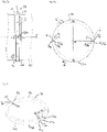
- FIG. 1 shows a plan view of a preferred embodiment of the sensor 10, ie a plan view of a peripheral surface F of the sensor 10, in particular of a connection area 3 described in more detail below, in a direction orthogonal to the axis of rotation Z of the sensor.
- the measured value sensor 10 comprises a carrier ring 1 and a measuring tape 2 arranged on the circumference thereof, for example glued on.
- the measured value sensor 10 can be mounted on a shaft 40 of an escalator by means of adjustment means 9 in the form of an elongated rubber band such as a double-sided adhesive tape .
- the width of the rubber band is selected to be larger than that of the carrier ring 1 and the tape measure 2.
- the width of the carrier ring 1 can be slightly larger than the tape measure 2, preferably 1 to 15% larger, more preferably 5 to 10% larger .
- the measuring value transmitter 10 is designed in two parts and has two preferably essentially semicircular elements of the carrier ring 1a, 1b and the measuring tape 2a, 2b (see also 2 ).
- the support ring 1 and the tape measure 2 are preferably divided in half into two elements 1a, 1b, 2a, 2b that are essentially the same size.
- the measuring value transmitter 10 can also be formed from several segments.
- the corresponding elements 1a, 1b, 2a, 2b can be selectively connected by means of connecting means 4, described in more detail below, at preferably two connecting areas 3 to form a continuous ring, ie a ring preferably without a continuous gap running through its cross section.
- the measuring tape 2 has a multiplicity of magnetic poles 5i arranged in the circumferential direction U. These are essentially uninterrupted and arranged alternately in the circumferential direction, which means that a north pole introduced into the tape measure is followed in the circumferential direction U by a south pole introduced into the tape measure.
- the respective poles 5i have a homogeneous pole length P L in the circumferential direction. This is preferably between 10 and 20mm and more preferably between 15 and 17mm in circumferential direction.
- This arrangement of the poles in the measuring tape provides a position coding of the measured value sensor and thus of the escalator shaft 40, which is determined by a suitable sensor system 20 (see Fig 2 ) can be read.
- the position coding has a periodically recurring signal Si with a predefined frequency.
- the measuring value transmitter 10 thus represents an incremental value transmitter for scanning by means of suitable sensors 20.
- the in 1 The magnetic poles 5i, 5a, 5b shown are equally contained in the respective tape measure according to the other exemplary embodiments, but have been partially omitted for the sake of clarity in the drawing.
- the magnetic poles 5i are now arranged on the measuring tape 2 or introduced into it by suitable magnetization such that an individual pole 5a, 5b of the poles 5i extends in the circumferential direction U of the measuring sensor 10 over the respective connection area 3.
- a single pole 5a thus extends over a first connecting area 3 of the measuring element elements 1a, 1b, 2a, 2b and a second pole 5b over a second, preferably opposite connecting area 3 of the measuring element elements 1a, 1b, 2a, 2b, respectively in a radial plan view of the respective pole 5a, 5b of the sensor.
- the exact polarity, north or south pole, of the respective individual pole 5a, 5b extending over the respective connection area 3 is preferably irrelevant.
- the respective connection area 3 of the carrier ring 1 and the measuring tape 2 is preferably a respective plane 3a on which the respective ends 11a, 11b, 12a, 12b of the carrier ring 1 and the measuring tape 2 are opposite.
- the respective connection area 3 of the carrier ring 1 and the measuring tape 2 or the connection plane 3a is opposite the circumferential direction U of the measuring sensor 10 and/or inclined relative to a planar side surface 1c, 1d of the carrier ring.
- This means that the respective connection area 3 does not run orthogonally to the circumferential direction U and/or to the side surface 1c in a plan view of the circumferential surface F of the measuring value sensor 10, but has an angle ⁇ to this.
- the angle ⁇ preferably has a value of 35-65°, more preferably 40 to 50° and most preferably a value of about 45°.
- connection plane 3a is in particular a respective gap between the respective ends 11a, 11b, 12a, 12b of the carrier ring 1 and the measuring tape 2.
- a gap between the respective ends of the carrier ring 11a, 11b can have a thickness of less than 1mm, preferably less than 0.6 mm.
- the respective gap of the carrier ring 1 is preferably not continuous in a cross-sectional view of the carrier ring 1, in particular due to the connecting means 4 of the carrier ring 1 partially arranged therein.
- a gap between the respective ends of the measuring tape 12a, 12b can have a thickness of less than 0.8 mm, preferably less than 0.3mm.
- connection area 3 or the connection plane 3a is preferably arranged in the middle or in a central area of the respective pole 5a, 5b extending over the connection area 3.
- the respective connection area 3 can divide the pole 5a, 5b extending over the connection area 3 approximately in half.
- the 2 shows a schematic side view of the system according to the invention having the sensor 10 described above and a sensor arrangement 20 for scanning the position coding of the sensor 10.
- the sensor arrangement 20 has only one sensor 21, preferably a sensor of the MR class or a Hall sensor.
- the Sensor 21 is preferably arranged in the radial direction of extent of the measuring transducer 10 in such a way that it is directed towards the peripheral surface F or that it can scan the magnetic measuring tape 2 rotating in the peripheral direction U.
- the sensor 21 is at a distance d of preferably greater than/equal to 10 mm from the peripheral surface F or outer surface of the measuring value transmitter 10 .
- the outer diameter D 2 of the measuring tape 2 and/or an outer diameter D 1 of the carrier ring 1 can be adapted to a predefined pole length P L of the magnetic poles 5i of the measuring tape, in particular in such a way that there is no magnetic gap or inconsistency in the circumferential direction U of the connected carrier ring 1 and Tape measure 2 is present.
- An inner diameter D i of the carrier ring 1 is preferably adapted to an outer diameter of the escalator shaft 40 .
- the adjusting means 9 already described above enable tolerance compensation when mounting the measuring value transmitter 10 on the shaft 40.
- the sensor arrangement 20 detects the magnetic field changes or the course of the magnetic field lines of the sensor 10 and calculates the position, speed and/or the acceleration of the shaft 40 from this and can do this forward to a control device 22.
- FIG. 3 shows a perspective view of a preferred embodiment of the carrier ring 1 of the measuring transducer 10.
- this has two essentially semicircular elements 1a, 1b, which can be connected to one another in a respective connecting region 3.
- the ring 1 is preferably manufactured as a turned part, then the bores and/or threads for the connecting means 4, which are described in more detail below, are set. Then takes place a separation of the ring 1 into preferably two halves 1a, 1b, with material being removed which can be compensated for by the connecting means 4.
- the carrier ring 1 has a homogeneous width with two parallel side surfaces 1c, 1d.
- the ring 1 also has a homogeneous inner and outer diameter D i , D 1 .
- the connecting means 4 of the support ring each have a through hole 15 for receiving a dowel or cylinder pin 15a (see also Figure 4c , 5c , 6c ) on.
- These through bores 15 extend axially offset to the connecting plane 3a of the support ring elements 1a, 1b.
- more than 60%, preferably more than 70%, of the area of the through bore 15 is arranged in a first support ring element 1a.
- the fitted dowel or cylinder pins 15a also make it possible to compensate for the material removal that occurs when the ring is separated.
- the connecting means 4 of the carrier ring 1 preferably also have a bore 6a for a screw connection 6 (see also Figures 4a-4e and Figures 6a-6e ), which is preferably arranged orthogonally to a connecting plane 3a of the carrier ring elements 1a, 1b.
- the carrier ring 1 can have two adjacent bores 7a, 7b in the respective ends of the carrier ring elements 1a, 1b, which can be connected by means of a suitable retaining plate 8a with fitted dowel or cylinder pins 8b (see also Figures 5a-5e and Figures 6a-6e ).
- the connecting means 4 of the carrier ring 1 preferably also each have two adjacent bores 7a, 7b in the respective ends of the Carrier ring elements 1a, 1b, which preferably run parallel to the axis of rotation Z of the carrier ring 1 and in which cylinder pins 8b connected to a holding plate 8a can be inserted.
- connecting means 4 described above can be combined according to the invention in different ways, as described below with reference to FIG Figures 4a-4e , 5a-5e and 6a-6e is described.
- the Figures 4a-4e show a first preferred exemplary embodiment, according to which the carrier ring elements 1a, 1b are connected to one another by means of the cylindrical pins 15a located in the bores 15.
- the carrier ring elements 1a, 1b are connected to one another by means of the screw connection 6.
- This is preferably arranged orthogonally to the connecting surface 3 of the carrier ring elements 1a, 1b and comprises a preferably stepped bore 6a, a threaded bore 6b arranged thereto in the respective other carrier ring element and an associated screw 6c.
- This arrangement of the connecting means 4 enables a secure connection of the individual carrier ring elements 1a, 1b, which can nevertheless be selectively separated, for example for maintenance purposes.
- the Figures 5a-5e show a second preferred exemplary embodiment, according to which the carrier ring elements 1a, 1b are connected to one another by means of the cylinder pins 15a located in the bores 15 and additionally by means of fitting or cylinder pins 8b inserted in the adjacent bores 7a, 7b of the respective carrier ring elements 1a, 1b. These are held by means of a holding plate 8a, which has two bores 14a, 14b arranged coaxially to the bores 7a, 7b. The ends of the dowel or cylindrical pins 8b opposite the holding plate 8a can be secured by means of a spring-elastic tensioning element 8c such as, for example, a mounting bracket.
- the connecting means described above enable a secure connection of the individual Carrier ring elements 1a, 1b, which is particularly easy to separate from each other and in particular without additional tools such as a screwdriver.
- the Figures 6a-6e show a third preferred embodiment, according to which the carrier ring elements 1a, 1b by means of a combination of in Figures 4a-4e and 5a-5e connecting means 4 shown is connected.
- the carrier ring elements 1a, 1b are connected to one another by means of the cylinder pins 15a located in the bores 15, additionally by means of dowel or cylinder pins 8b inserted in the adjacent bores 7a, 7b of the respective carrier ring elements 1a, 1b, and furthermore additionally by means of the previously described screw connection 6 tied together.
- the connecting means described above enable a very secure connection of the individual support ring elements 1a, 1b, which can nevertheless be easily separated from one another, for example for maintenance purposes.
- connection area 3 of the carrier ring 1 and the tape measure 2 is preferably arranged orthogonally to the circumferential direction U of the measuring transducer 10 and/or to a planar side surface 1c, 1d of the carrier ring.
- the connection area is preferably a plane 3a, on which the respective ends 11a, 11b, 12a, 12b of the carrier ring 1 and the measuring tape 2 lie opposite one another in an essentially parallel manner.
- the connection area 3 is preferably in a central area M (between the dashed lines in Figure 7a ) of the respective pole 5a, 5b arranged.
- the central area M preferably extends parallel to the axis of rotation Z and preferably has an area of up to 50%, more preferably up to 25% of the pole extending over the connection area.
- the measuring value sensor 10 shown here also has connecting means, which preferably each have a bore 15 with a cylindrical pin 15a inserted therein (see FIG Figures 7b and 7c ).
- the bore 15 and the cylinder pin 15a used preferably run parallel to the connecting plane 3a.
- the bore 15 and the cylinder pin 15a are preferably arranged parallel to the axis of rotation Z here.
- the respective through hole 15 extends axially offset to the connecting plane 3a of the carrier ring elements 1a, 1b.
- more than 60%, preferably more than 70%, of the area of the through bore 15 is arranged in a first support ring element 1a.
- the connecting means 4 can additionally or alternatively each have a screw connection 6 and/or a connection by means of adjacent bores 7a, 7b in the respective carrier ring elements 1a, 1b, which can be secured by means of a retaining plate 8a (in the Figures 7a-7c not shown) and fitted therein dowel or cylindrical pins 8b can be connected.
Landscapes
- Physics & Mathematics (AREA)
- General Physics & Mathematics (AREA)
- Measurement Of Length, Angles, Or The Like Using Electric Or Magnetic Means (AREA)
- Transmission And Conversion Of Sensor Element Output (AREA)
Claims (25)
- Transmetteur de signaux (10) pour un arbre (40) d'un escalier mécanique pour fournir un codage de position, ledit transmetteur de signaux (10) comprenant un anneau de support (1) et un mètre à ruban (2) magnétique disposé sur le côté de circonférence sur ledit anneau de support (1), l'anneau de support (1) et le mètre à ruban (2) étant réalisés en deux parties en forme d'éléments (1a, 1b, 2a, 2b) qui sont, de préférence, semi-circulaires et étant capables d'être reliés l'un à l'autre dans une zone de liaison (3) respective sélectivement via des moyens de liaison (4) de l'anneau de support (1), le mètre à ruban (2) ayant une pluralité de pôles (5i) magnétiques disposés dans la direction de circonférence, caractérisé en ce que les pôles (5i) magnétiques sont disposés dans le mètre à ruban (2) de telle manière qu'un seul pôle (5a, 5b) magnétique s'étend sur chaque zone de liaison (3) respective de l'anneau de support (1) et du mètre à ruban (2) dans la direction de circonférence (U) du transmetteur de signaux (10).
- Transmetteur de signaux selon la revendication 1, caractérisé en ce que la zone de liaison (3) respective de l'anneau de support (1) et du mètre à ruban (2) est disposée de manière inclinée par rapport à une direction de circonférence (U) du transmetteur de signaux (10)
- Transmetteur de signaux selon la revendication 2, caractérisé en ce que la zone de liaison (3) respective est disposée par rapport à une direction de circonférence (U) du transmetteur de signaux (10) selon un angle (a) de 35° à 65°, plus préférentiellement de 40° à 50° et, de la manière la plus préférée, selon un angle d'environ 45°.
- Transmetteur de signaux selon l'une quelconque des revendications précédente, caractérisé en ce que les pôles (5i) sont disposés de telle manière que la zone de liaison (3) respective divise le pôle (5a, 5b) qui s'étend sur la zone de liaison (3) en deux moitiés approximativement égales et/ou que le pôle (5a, 5b) qui s'étend sur la zone de liaison respective est approximativement centré sur ladite zone de liaison.
- Transmetteur de signaux selon l'une quelconque des revendications précédente, caractérisé en ce que la zone de liaison (3) respective est un plan (3a) sur lequel les extrémités (11a, 11b, 12a, 12b) respectives de l'anneau de support (1) et/ou du mètre à ruban (2) sont opposées.
- Transmetteur de signaux selon l'une quelconque des revendications précédente, caractérisé en ce qu'une fente (16a) située dans la zone de liaison (3) a une épaisseur inférieure à 1 mm, de préférence inférieure à 0,6 mm, entre les extrémités respectives de l'anneau de support (11a, 11b).
- Transmetteur de signaux selon l'une quelconque des revendications précédente, caractérisé en ce qu'une fente (16b) située dans la zone de liaison (3) a une épaisseur inférieure à 0,8 mm, de préférence inférieure à 0,3 mm, entre les extrémités respectives du mètre à ruban (12a, 12b).
- Transmetteur de signaux selon l'une quelconque des revendications précédente, caractérisé en ce que les pôles (5i) magnétiques du mètre à ruban sont disposés essentiellement sans interruption dans la direction de circonférence (U).
- Transmetteur de signaux selon l'une quelconque des revendications précédente, caractérisé en ce que les pôles (5i) magnétiques du mètre à ruban (2) sont disposés de manière alternée dans la direction de circonférence (U).
- Transmetteur de signaux selon l'une quelconque des revendications précédente, caractérisé en ce que les pôles (5i) magnétiques du mètre à ruban (2) ont une longueur de pôle (PL) homogène dans la direction de circonférence (U).
- Transmetteur de signaux selon l'une quelconque des revendications précédente, caractérisé en ce qu'une longueur de pôle (PL) des pôles (5i) du mètre à ruban (2) est entre 10 à 20 mm et, de préférence, entre 15 et 17 mm dans la direction de circonférence (U).
- Transmetteur de signaux selon l'une quelconque des revendications précédente, caractérisé en ce que le codage de position forme une échelle qui est capable d'être lue par un capteur (21) approprié.
- Transmetteur de signaux selon l'une quelconque des revendications précédente, caractérisé en ce que le codage de position a un signal (Si) se répétant périodiquement ayant une fréquence prédéfinie.
- Transmetteur de signaux selon l'une quelconque des revendications précédente, caractérisé en ce qu'un diamètre extérieur (D2) du mètre à ruban (2) et/ou un diamètre extérieur (D1) de l'anneau de support (1) sont/est adapté/s à une longueur de pôle (PL) prédéfinie des pôles (5i) magnétiques dans la direction de circonférence (U) de telle manière qu'il n'existe aucun vide magnétique ou aucune incohérence magnétique dans la direction de circonférence (U) de l'anneau de support (1) relié et du mètre à ruban (2).
- Transmetteur de signaux selon l'une quelconque des revendications précédente, caractérisé en ce que le codage de position a été introduit au moyen de la magnétisation du mètre à ruban (2) et de l'anneau de support (1) dans l'état relié.
- Transmetteur de signaux selon l'une quelconque des revendications précédente, caractérisé en ce que chaque moyen de liaison (4) a au moins un trou traversant (15) pour loger une goupille de positionnement (15a), ledit trou traversant (15) s'étendant parallèlement à un plan (3a) de liaison des éléments (1a, 1b) d'anneau de support et s'étendant, de préférence, de manière à être axialement décalé au plan (3a) de liaison des éléments d'anneau de support.
- Transmetteur de signaux selon l'une quelconque des revendications précédente, caractérisé en ce que chaque moyen de liaison (4) a au moins un assemblage par vis (6) qui est disposé, de préférence, orthogonalement à un plan (3a) de liaison des éléments (1a, 1b) d'anneau de support.
- Transmetteur de signaux selon l'une quelconque des revendications précédente, caractérisé en ce que chaque moyen de liaison (4) a deux forages (7a, 7b) adjacents dans les extrémités respectives des éléments (1a, 1b) d'anneau de support et un élément de serrage (8c) à élasticité de ressort prévu pour fixer des goupilles cylindriques (8b), lesdits forages (7a, 7b) s'étendant, de préférence, parallèlement à l'axe de rotation (Z) de l'anneau de support (1) et des goupilles cylindriques (8b) reliées à une plaque de retenue (8a) étant insérables dans lesdits forages (7a, 7b).
- Transmetteur de signaux selon l'une quelconque des revendications précédente, caractérisé en ce que le transmetteur de signaux (10) a des moyens d'ajustage (9) en forme d'au moins un ruban en caoutchouc oblong, de préférence d'un ruban adhésif double face, qui est capable d'être disposé entre l'arbre (40) et l'anneau de support (1).
- Transmetteur de signaux selon l'une quelconque des revendications précédente, caractérisé en ce que l'anneau de support (1) est en métal, de préférence en fer, et/ou en ce que le mètre à ruban (2) est en plastique ferromagnétique, de préférence en un élastomère ayant des particules ferromagnétiques incorporées dans celui-ci.
- Système de mesure (30) comprenant un transmetteur de signaux (10) selon l'une quelconque des revendications précédentes et un agencement de capteur (20) pour échantillonner le codage de position du transmetteur de signaux.
- Système de mesure selon la revendication 21, caractérisé en ce que l'agencement de capteur (20) n'a qu'un seul capteur, de préférence un capteur (21) de la classe MR.
- Système de mesure selon la revendication 21 ou 22, caractérisé en ce que l'agencement de capteur (20) est configuré pour transmettre la position, la vitesse et/ou l'accélération de l'arbre (40) à une commande supérieure (22).
- Système de mesure selon l'une quelconque des revendications 21 à 23, caractérisé en ce que l'agencement de capteur (20) est espacé d'une distance (d) de supérieure/égale à 10 mm d'une surface extérieure (F) du transmetteur de signaux (10).
- Système de mesure selon l'une quelconque des revendications 21 à 24, caractérisé en ce que l'agencement de capteur (20) a un temps de réponse d'inférieur à 300 ms et, de préférence, d'inférieur à 150 ms.
Applications Claiming Priority (1)
| Application Number | Priority Date | Filing Date | Title |
|---|---|---|---|
| PCT/EP2019/051272 WO2020147969A1 (fr) | 2019-01-18 | 2019-01-18 | Capteur de mesure pour cage d'escalier roulant |
Publications (2)
| Publication Number | Publication Date |
|---|---|
| EP3884241A1 EP3884241A1 (fr) | 2021-09-29 |
| EP3884241B1 true EP3884241B1 (fr) | 2022-11-02 |
Family
ID=65351994
Family Applications (1)
| Application Number | Title | Priority Date | Filing Date |
|---|---|---|---|
| EP19703950.6A Active EP3884241B1 (fr) | 2019-01-18 | 2019-01-18 | Codeur de mesure pour arbre d'escalator |
Country Status (3)
| Country | Link |
|---|---|
| EP (1) | EP3884241B1 (fr) |
| CN (1) | CN111712690B (fr) |
| WO (1) | WO2020147969A1 (fr) |
Families Citing this family (3)
| Publication number | Priority date | Publication date | Assignee | Title |
|---|---|---|---|---|
| DE102020003964A1 (de) | 2020-07-02 | 2022-01-05 | Baumer Hübner GmbH | Verfahren zur Herstellung einer Maßverkörperung |
| CN112504046A (zh) * | 2020-12-01 | 2021-03-16 | 四川航天长征装备制造有限公司 | 一种恒拉力曲线长度测量装置 |
| CN119197247A (zh) * | 2024-09-27 | 2024-12-27 | 四川航天长征装备制造有限公司 | 一种航天用大型整体旋压锥底零件周长快速测量方法 |
Citations (3)
| Publication number | Priority date | Publication date | Assignee | Title |
|---|---|---|---|---|
| US4002937A (en) * | 1975-07-03 | 1977-01-11 | Dickey-John Corporation | Magnetic sensing device |
| EP1612564A2 (fr) * | 2001-09-11 | 2006-01-04 | Koyo Seiko Company, Ltd. | Anneau d'impulsion aimanté |
| EP2660610A2 (fr) * | 2012-05-04 | 2013-11-06 | Leine & Linde Ab | Bague de support pour codeur |
Family Cites Families (9)
| Publication number | Priority date | Publication date | Assignee | Title |
|---|---|---|---|---|
| DE10211155A1 (de) * | 2002-03-14 | 2003-09-25 | Heidenhain Gmbh Dr Johannes | Verfahren zur Herstellung eines ringförmigen Maßstabs |
| DE102010030121B4 (de) * | 2009-08-13 | 2014-12-31 | Johannes Hübner Fabrik elektrischer Maschinen GmbH | Polradanordnung für einen Drehgeber |
| DE202010007285U1 (de) * | 2010-05-21 | 2011-09-23 | Balluff Gmbh | Maßkörpervorrichtung für ein Positions-/Wegmesssystem, Positions-/Wegmesssystem und Anwendung, an welcher ein Positions-/Wegmesssystem montiert ist |
| DE102010061738A1 (de) | 2010-11-22 | 2012-04-26 | Baumer Innotec Ag | Verfahren und Inkrementalwertgeber zur Bestimmung einer Istlage eines Körpers entlang eines Messweges mit einer wenigstens eine Lücke aufweisenden Maßverkörperung |
| CN102759308B (zh) * | 2011-04-26 | 2016-12-14 | Asm自动化传感器测量技术有限公司 | 具有卷尺的测量环以及用于布置卷尺的方法 |
| SE539190C2 (sv) | 2012-05-04 | 2017-05-09 | Leine & Linde Ab | Ett sensorhuvud för en pulsgivare |
| CN104340835B (zh) | 2013-07-26 | 2016-12-07 | 上海三菱电梯有限公司 | 乘客输送设备的安全检测装置及其实现方法 |
| CN104370199A (zh) * | 2014-11-11 | 2015-02-25 | 瑞电士(常熟)传感器有限公司 | 自动扶梯测速系统 |
| CN208315310U (zh) * | 2018-06-20 | 2019-01-01 | 长春禹衡光学有限公司 | 一种用于磁编码器的磁环组件 |
-
2019
- 2019-01-18 EP EP19703950.6A patent/EP3884241B1/fr active Active
- 2019-01-18 CN CN201980003888.5A patent/CN111712690B/zh active Active
- 2019-01-18 WO PCT/EP2019/051272 patent/WO2020147969A1/fr not_active Ceased
Patent Citations (3)
| Publication number | Priority date | Publication date | Assignee | Title |
|---|---|---|---|---|
| US4002937A (en) * | 1975-07-03 | 1977-01-11 | Dickey-John Corporation | Magnetic sensing device |
| EP1612564A2 (fr) * | 2001-09-11 | 2006-01-04 | Koyo Seiko Company, Ltd. | Anneau d'impulsion aimanté |
| EP2660610A2 (fr) * | 2012-05-04 | 2013-11-06 | Leine & Linde Ab | Bague de support pour codeur |
Also Published As
| Publication number | Publication date |
|---|---|
| EP3884241A1 (fr) | 2021-09-29 |
| WO2020147969A1 (fr) | 2020-07-23 |
| CN111712690B (zh) | 2022-07-01 |
| CN111712690A (zh) | 2020-09-25 |
Similar Documents
| Publication | Publication Date | Title |
|---|---|---|
| EP1357365B1 (fr) | Détecteur de position | |
| DE10037211B4 (de) | Lenkradstellungssensor | |
| EP1408305B1 (fr) | Dispositif de mesure de l'angle absolu d'un arbre tournant | |
| EP3403056B1 (fr) | Assemblage d'un détecteur de rotation à un boîtier | |
| EP1873534B1 (fr) | Dispositif pour déterminer, sans contact, la vitesse de rotation et/ou la position d'un objet doté d'un codeur | |
| EP3884241B1 (fr) | Codeur de mesure pour arbre d'escalator | |
| DE19716985A1 (de) | Vorrichtung zur Ermittlung der Position und/oder Torsion rotierender Wellen | |
| EP1927824B1 (fr) | Encodeur | |
| WO2013186001A1 (fr) | Bague magnétique d'un système de détection de position de rotor d'un moteur électrique électriquement commuté | |
| DE112007002698T5 (de) | Vorrichtung zum Erfassen des von einer Welle übertragenen Drehmoments | |
| EP3207337B1 (fr) | Capteur pour déterminer au moins une propriété de rotation d'un élément en rotation | |
| DE10310567A1 (de) | Lagerbaugruppe mit Rotationssensor, der in der Lage ist, die Nullstellung zu erfassen | |
| EP3590812A1 (fr) | Système de mesure incrémental pour une bicyclette, bicyclette, moyen émetteur de signal et procédé de fabrication | |
| DE102013006379A1 (de) | Sensorvorrichtung mit einer Drehmomentsensoreinrichtung und einer Inkrementalsensoreinrichtung und Kraftfahrzeug | |
| EP2479539B1 (fr) | Dispositif de mesure d'angle | |
| DE102010030121B4 (de) | Polradanordnung für einen Drehgeber | |
| DE102008051242B4 (de) | Polrad und Montageverfahren hierfür | |
| DE102011076284A1 (de) | Lagereinheit mit Winkelmesssystem | |
| DE102009038087A1 (de) | Kugelgewindetrieb | |
| EP2343506A2 (fr) | Dispositif de mesure de longueur | |
| DE102005061347A1 (de) | Anordnung zur Messung des absoluten Drehwinkels einer Welle | |
| EP3128294B1 (fr) | Capteur de determination de la position angulaire d'un moteur et moteur comprenant un capteur destine a determiner la position angulaire | |
| DE102004026476A1 (de) | Vorrichtung zur rotativen Winkelmessung | |
| DE102006020700A1 (de) | Einrichtung zur Drehwinkelerfassung | |
| DE102008046540A1 (de) | Wälzlageranordnung mit Drehwinkelgeber |
Legal Events
| Date | Code | Title | Description |
|---|---|---|---|
| STAA | Information on the status of an ep patent application or granted ep patent |
Free format text: STATUS: UNKNOWN |
|
| STAA | Information on the status of an ep patent application or granted ep patent |
Free format text: STATUS: THE INTERNATIONAL PUBLICATION HAS BEEN MADE |
|
| TPAC | Observations filed by third parties |
Free format text: ORIGINAL CODE: EPIDOSNTIPA |
|
| PUAI | Public reference made under article 153(3) epc to a published international application that has entered the european phase |
Free format text: ORIGINAL CODE: 0009012 |
|
| STAA | Information on the status of an ep patent application or granted ep patent |
Free format text: STATUS: REQUEST FOR EXAMINATION WAS MADE |
|
| 17P | Request for examination filed |
Effective date: 20210623 |
|
| AK | Designated contracting states |
Kind code of ref document: A1 Designated state(s): AL AT BE BG CH CY CZ DE DK EE ES FI FR GB GR HR HU IE IS IT LI LT LU LV MC MK MT NL NO PL PT RO RS SE SI SK SM TR |
|
| DAV | Request for validation of the european patent (deleted) | ||
| DAX | Request for extension of the european patent (deleted) | ||
| GRAP | Despatch of communication of intention to grant a patent |
Free format text: ORIGINAL CODE: EPIDOSNIGR1 |
|
| STAA | Information on the status of an ep patent application or granted ep patent |
Free format text: STATUS: GRANT OF PATENT IS INTENDED |
|
| RIC1 | Information provided on ipc code assigned before grant |
Ipc: G01D 5/245 20060101ALI20220429BHEP Ipc: G01D 5/244 20060101ALI20220429BHEP Ipc: G01D 5/347 20060101AFI20220429BHEP |
|
| INTG | Intention to grant announced |
Effective date: 20220517 |
|
| GRAS | Grant fee paid |
Free format text: ORIGINAL CODE: EPIDOSNIGR3 |
|
| GRAA | (expected) grant |
Free format text: ORIGINAL CODE: 0009210 |
|
| STAA | Information on the status of an ep patent application or granted ep patent |
Free format text: STATUS: THE PATENT HAS BEEN GRANTED |
|
| AK | Designated contracting states |
Kind code of ref document: B1 Designated state(s): AL AT BE BG CH CY CZ DE DK EE ES FI FR GB GR HR HU IE IS IT LI LT LU LV MC MK MT NL NO PL PT RO RS SE SI SK SM TR |
|
| REG | Reference to a national code |
Ref country code: GB Ref legal event code: FG4D Free format text: NOT ENGLISH |
|
| REG | Reference to a national code |
Ref country code: CH Ref legal event code: EP Ref country code: AT Ref legal event code: REF Ref document number: 1529053 Country of ref document: AT Kind code of ref document: T Effective date: 20221115 |
|
| REG | Reference to a national code |
Ref country code: DE Ref legal event code: R096 Ref document number: 502019006123 Country of ref document: DE |
|
| REG | Reference to a national code |
Ref country code: IE Ref legal event code: FG4D Free format text: LANGUAGE OF EP DOCUMENT: GERMAN |
|
| REG | Reference to a national code |
Ref country code: LT Ref legal event code: MG9D |
|
| REG | Reference to a national code |
Ref country code: NL Ref legal event code: MP Effective date: 20221102 |
|
| PG25 | Lapsed in a contracting state [announced via postgrant information from national office to epo] |
Ref country code: SE Free format text: LAPSE BECAUSE OF FAILURE TO SUBMIT A TRANSLATION OF THE DESCRIPTION OR TO PAY THE FEE WITHIN THE PRESCRIBED TIME-LIMIT Effective date: 20221102 Ref country code: PT Free format text: LAPSE BECAUSE OF FAILURE TO SUBMIT A TRANSLATION OF THE DESCRIPTION OR TO PAY THE FEE WITHIN THE PRESCRIBED TIME-LIMIT Effective date: 20230302 Ref country code: NO Free format text: LAPSE BECAUSE OF FAILURE TO SUBMIT A TRANSLATION OF THE DESCRIPTION OR TO PAY THE FEE WITHIN THE PRESCRIBED TIME-LIMIT Effective date: 20230202 Ref country code: LT Free format text: LAPSE BECAUSE OF FAILURE TO SUBMIT A TRANSLATION OF THE DESCRIPTION OR TO PAY THE FEE WITHIN THE PRESCRIBED TIME-LIMIT Effective date: 20221102 Ref country code: FI Free format text: LAPSE BECAUSE OF FAILURE TO SUBMIT A TRANSLATION OF THE DESCRIPTION OR TO PAY THE FEE WITHIN THE PRESCRIBED TIME-LIMIT Effective date: 20221102 Ref country code: ES Free format text: LAPSE BECAUSE OF FAILURE TO SUBMIT A TRANSLATION OF THE DESCRIPTION OR TO PAY THE FEE WITHIN THE PRESCRIBED TIME-LIMIT Effective date: 20221102 |
|
| PG25 | Lapsed in a contracting state [announced via postgrant information from national office to epo] |
Ref country code: RS Free format text: LAPSE BECAUSE OF FAILURE TO SUBMIT A TRANSLATION OF THE DESCRIPTION OR TO PAY THE FEE WITHIN THE PRESCRIBED TIME-LIMIT Effective date: 20221102 Ref country code: PL Free format text: LAPSE BECAUSE OF FAILURE TO SUBMIT A TRANSLATION OF THE DESCRIPTION OR TO PAY THE FEE WITHIN THE PRESCRIBED TIME-LIMIT Effective date: 20221102 Ref country code: LV Free format text: LAPSE BECAUSE OF FAILURE TO SUBMIT A TRANSLATION OF THE DESCRIPTION OR TO PAY THE FEE WITHIN THE PRESCRIBED TIME-LIMIT Effective date: 20221102 Ref country code: IS Free format text: LAPSE BECAUSE OF FAILURE TO SUBMIT A TRANSLATION OF THE DESCRIPTION OR TO PAY THE FEE WITHIN THE PRESCRIBED TIME-LIMIT Effective date: 20230302 Ref country code: HR Free format text: LAPSE BECAUSE OF FAILURE TO SUBMIT A TRANSLATION OF THE DESCRIPTION OR TO PAY THE FEE WITHIN THE PRESCRIBED TIME-LIMIT Effective date: 20221102 Ref country code: GR Free format text: LAPSE BECAUSE OF FAILURE TO SUBMIT A TRANSLATION OF THE DESCRIPTION OR TO PAY THE FEE WITHIN THE PRESCRIBED TIME-LIMIT Effective date: 20230203 |
|
| PG25 | Lapsed in a contracting state [announced via postgrant information from national office to epo] |
Ref country code: NL Free format text: LAPSE BECAUSE OF FAILURE TO SUBMIT A TRANSLATION OF THE DESCRIPTION OR TO PAY THE FEE WITHIN THE PRESCRIBED TIME-LIMIT Effective date: 20221102 |
|
| PG25 | Lapsed in a contracting state [announced via postgrant information from national office to epo] |
Ref country code: SM Free format text: LAPSE BECAUSE OF FAILURE TO SUBMIT A TRANSLATION OF THE DESCRIPTION OR TO PAY THE FEE WITHIN THE PRESCRIBED TIME-LIMIT Effective date: 20221102 Ref country code: RO Free format text: LAPSE BECAUSE OF FAILURE TO SUBMIT A TRANSLATION OF THE DESCRIPTION OR TO PAY THE FEE WITHIN THE PRESCRIBED TIME-LIMIT Effective date: 20221102 Ref country code: EE Free format text: LAPSE BECAUSE OF FAILURE TO SUBMIT A TRANSLATION OF THE DESCRIPTION OR TO PAY THE FEE WITHIN THE PRESCRIBED TIME-LIMIT Effective date: 20221102 Ref country code: DK Free format text: LAPSE BECAUSE OF FAILURE TO SUBMIT A TRANSLATION OF THE DESCRIPTION OR TO PAY THE FEE WITHIN THE PRESCRIBED TIME-LIMIT Effective date: 20221102 Ref country code: CZ Free format text: LAPSE BECAUSE OF FAILURE TO SUBMIT A TRANSLATION OF THE DESCRIPTION OR TO PAY THE FEE WITHIN THE PRESCRIBED TIME-LIMIT Effective date: 20221102 |
|
| REG | Reference to a national code |
Ref country code: DE Ref legal event code: R097 Ref document number: 502019006123 Country of ref document: DE |
|
| PG25 | Lapsed in a contracting state [announced via postgrant information from national office to epo] |
Ref country code: SK Free format text: LAPSE BECAUSE OF FAILURE TO SUBMIT A TRANSLATION OF THE DESCRIPTION OR TO PAY THE FEE WITHIN THE PRESCRIBED TIME-LIMIT Effective date: 20221102 Ref country code: AL Free format text: LAPSE BECAUSE OF FAILURE TO SUBMIT A TRANSLATION OF THE DESCRIPTION OR TO PAY THE FEE WITHIN THE PRESCRIBED TIME-LIMIT Effective date: 20221102 |
|
| REG | Reference to a national code |
Ref country code: CH Ref legal event code: PL |
|
| PLBE | No opposition filed within time limit |
Free format text: ORIGINAL CODE: 0009261 |
|
| STAA | Information on the status of an ep patent application or granted ep patent |
Free format text: STATUS: NO OPPOSITION FILED WITHIN TIME LIMIT |
|
| PG25 | Lapsed in a contracting state [announced via postgrant information from national office to epo] |
Ref country code: LU Free format text: LAPSE BECAUSE OF NON-PAYMENT OF DUE FEES Effective date: 20230118 |
|
| REG | Reference to a national code |
Ref country code: BE Ref legal event code: MM Effective date: 20230131 |
|
| 26N | No opposition filed |
Effective date: 20230803 |
|
| GBPC | Gb: european patent ceased through non-payment of renewal fee |
Effective date: 20230202 |
|
| PG25 | Lapsed in a contracting state [announced via postgrant information from national office to epo] |
Ref country code: LI Free format text: LAPSE BECAUSE OF NON-PAYMENT OF DUE FEES Effective date: 20230131 Ref country code: CH Free format text: LAPSE BECAUSE OF NON-PAYMENT OF DUE FEES Effective date: 20230131 |
|
| PG25 | Lapsed in a contracting state [announced via postgrant information from national office to epo] |
Ref country code: SI Free format text: LAPSE BECAUSE OF FAILURE TO SUBMIT A TRANSLATION OF THE DESCRIPTION OR TO PAY THE FEE WITHIN THE PRESCRIBED TIME-LIMIT Effective date: 20221102 Ref country code: FR Free format text: LAPSE BECAUSE OF NON-PAYMENT OF DUE FEES Effective date: 20230131 Ref country code: BE Free format text: LAPSE BECAUSE OF NON-PAYMENT OF DUE FEES Effective date: 20230131 |
|
| PG25 | Lapsed in a contracting state [announced via postgrant information from national office to epo] |
Ref country code: GB Free format text: LAPSE BECAUSE OF NON-PAYMENT OF DUE FEES Effective date: 20230202 |
|
| PG25 | Lapsed in a contracting state [announced via postgrant information from national office to epo] |
Ref country code: IE Free format text: LAPSE BECAUSE OF NON-PAYMENT OF DUE FEES Effective date: 20230118 Ref country code: GB Free format text: LAPSE BECAUSE OF NON-PAYMENT OF DUE FEES Effective date: 20230202 |
|
| PG25 | Lapsed in a contracting state [announced via postgrant information from national office to epo] |
Ref country code: IT Free format text: LAPSE BECAUSE OF FAILURE TO SUBMIT A TRANSLATION OF THE DESCRIPTION OR TO PAY THE FEE WITHIN THE PRESCRIBED TIME-LIMIT Effective date: 20221102 |
|
| PG25 | Lapsed in a contracting state [announced via postgrant information from national office to epo] |
Ref country code: MC Free format text: LAPSE BECAUSE OF FAILURE TO SUBMIT A TRANSLATION OF THE DESCRIPTION OR TO PAY THE FEE WITHIN THE PRESCRIBED TIME-LIMIT Effective date: 20221102 |
|
| PG25 | Lapsed in a contracting state [announced via postgrant information from national office to epo] |
Ref country code: MC Free format text: LAPSE BECAUSE OF FAILURE TO SUBMIT A TRANSLATION OF THE DESCRIPTION OR TO PAY THE FEE WITHIN THE PRESCRIBED TIME-LIMIT Effective date: 20221102 |
|
| PG25 | Lapsed in a contracting state [announced via postgrant information from national office to epo] |
Ref country code: BG Free format text: LAPSE BECAUSE OF FAILURE TO SUBMIT A TRANSLATION OF THE DESCRIPTION OR TO PAY THE FEE WITHIN THE PRESCRIBED TIME-LIMIT Effective date: 20221102 |
|
| PG25 | Lapsed in a contracting state [announced via postgrant information from national office to epo] |
Ref country code: BG Free format text: LAPSE BECAUSE OF FAILURE TO SUBMIT A TRANSLATION OF THE DESCRIPTION OR TO PAY THE FEE WITHIN THE PRESCRIBED TIME-LIMIT Effective date: 20221102 |
|
| REG | Reference to a national code |
Ref country code: AT Ref legal event code: MM01 Ref document number: 1529053 Country of ref document: AT Kind code of ref document: T Effective date: 20240118 |
|
| PG25 | Lapsed in a contracting state [announced via postgrant information from national office to epo] |
Ref country code: AT Free format text: LAPSE BECAUSE OF NON-PAYMENT OF DUE FEES Effective date: 20240118 |
|
| PG25 | Lapsed in a contracting state [announced via postgrant information from national office to epo] |
Ref country code: CY Free format text: LAPSE BECAUSE OF FAILURE TO SUBMIT A TRANSLATION OF THE DESCRIPTION OR TO PAY THE FEE WITHIN THE PRESCRIBED TIME-LIMIT; INVALID AB INITIO Effective date: 20190118 |
|
| PG25 | Lapsed in a contracting state [announced via postgrant information from national office to epo] |
Ref country code: HU Free format text: LAPSE BECAUSE OF FAILURE TO SUBMIT A TRANSLATION OF THE DESCRIPTION OR TO PAY THE FEE WITHIN THE PRESCRIBED TIME-LIMIT; INVALID AB INITIO Effective date: 20190118 |
|
| PG25 | Lapsed in a contracting state [announced via postgrant information from national office to epo] |
Ref country code: TR Free format text: LAPSE BECAUSE OF FAILURE TO SUBMIT A TRANSLATION OF THE DESCRIPTION OR TO PAY THE FEE WITHIN THE PRESCRIBED TIME-LIMIT Effective date: 20221102 |
|
| PGFP | Annual fee paid to national office [announced via postgrant information from national office to epo] |
Ref country code: DE Payment date: 20260126 Year of fee payment: 8 |
|
| PGFP | Annual fee paid to national office [announced via postgrant information from national office to epo] |
Ref country code: AT Payment date: 20260410 Year of fee payment: 5 |