EP3590812A1 - Système de mesure incrémental pour une bicyclette, bicyclette, moyen émetteur de signal et procédé de fabrication - Google Patents
Système de mesure incrémental pour une bicyclette, bicyclette, moyen émetteur de signal et procédé de fabrication Download PDFInfo
- Publication number
- EP3590812A1 EP3590812A1 EP19184336.6A EP19184336A EP3590812A1 EP 3590812 A1 EP3590812 A1 EP 3590812A1 EP 19184336 A EP19184336 A EP 19184336A EP 3590812 A1 EP3590812 A1 EP 3590812A1
- Authority
- EP
- European Patent Office
- Prior art keywords
- signal
- path system
- bicycle
- wheel
- optionally
- Prior art date
- Legal status (The legal status is an assumption and is not a legal conclusion. Google has not performed a legal analysis and makes no representation as to the accuracy of the status listed.)
- Granted
Links
Images


Classifications
-
- B—PERFORMING OPERATIONS; TRANSPORTING
- B62—LAND VEHICLES FOR TRAVELLING OTHERWISE THAN ON RAILS
- B62M—RIDER PROPULSION OF WHEELED VEHICLES OR SLEDGES; POWERED PROPULSION OF SLEDGES OR SINGLE-TRACK CYCLES; TRANSMISSIONS SPECIALLY ADAPTED FOR SUCH VEHICLES
- B62M6/00—Rider propulsion of wheeled vehicles with additional source of power, e.g. combustion engine or electric motor
- B62M6/40—Rider propelled cycles with auxiliary electric motor
- B62M6/45—Control or actuating devices therefor
- B62M6/50—Control or actuating devices therefor characterised by detectors or sensors, or arrangement thereof
-
- B—PERFORMING OPERATIONS; TRANSPORTING
- B62—LAND VEHICLES FOR TRAVELLING OTHERWISE THAN ON RAILS
- B62J—CYCLE SADDLES OR SEATS; AUXILIARY DEVICES OR ACCESSORIES SPECIALLY ADAPTED TO CYCLES AND NOT OTHERWISE PROVIDED FOR, e.g. ARTICLE CARRIERS OR CYCLE PROTECTORS
- B62J45/00—Electrical equipment arrangements specially adapted for use as accessories on cycles, not otherwise provided for
- B62J45/40—Sensor arrangements; Mounting thereof
- B62J45/41—Sensor arrangements; Mounting thereof characterised by the type of sensor
- B62J45/413—Rotation sensors
-
- B—PERFORMING OPERATIONS; TRANSPORTING
- B62—LAND VEHICLES FOR TRAVELLING OTHERWISE THAN ON RAILS
- B62J—CYCLE SADDLES OR SEATS; AUXILIARY DEVICES OR ACCESSORIES SPECIALLY ADAPTED TO CYCLES AND NOT OTHERWISE PROVIDED FOR, e.g. ARTICLE CARRIERS OR CYCLE PROTECTORS
- B62J45/00—Electrical equipment arrangements specially adapted for use as accessories on cycles, not otherwise provided for
- B62J45/40—Sensor arrangements; Mounting thereof
- B62J45/42—Sensor arrangements; Mounting thereof characterised by mounting
- B62J45/423—Sensor arrangements; Mounting thereof characterised by mounting on or besides the wheel
-
- G—PHYSICS
- G01—MEASURING; TESTING
- G01P—MEASURING LINEAR OR ANGULAR SPEED, ACCELERATION, DECELERATION, OR SHOCK; INDICATING PRESENCE, ABSENCE, OR DIRECTION, OF MOVEMENT
- G01P21/00—Testing or calibrating of apparatus or devices covered by the preceding groups
- G01P21/02—Testing or calibrating of apparatus or devices covered by the preceding groups of speedometers
-
- G—PHYSICS
- G01—MEASURING; TESTING
- G01P—MEASURING LINEAR OR ANGULAR SPEED, ACCELERATION, DECELERATION, OR SHOCK; INDICATING PRESENCE, ABSENCE, OR DIRECTION, OF MOVEMENT
- G01P3/00—Measuring linear or angular speed; Measuring differences of linear or angular speeds
- G01P3/42—Devices characterised by the use of electric or magnetic means
- G01P3/44—Devices characterised by the use of electric or magnetic means for measuring angular speed
- G01P3/48—Devices characterised by the use of electric or magnetic means for measuring angular speed by measuring frequency of generated current or voltage
- G01P3/481—Devices characterised by the use of electric or magnetic means for measuring angular speed by measuring frequency of generated current or voltage of pulse signals
-
- B—PERFORMING OPERATIONS; TRANSPORTING
- B62—LAND VEHICLES FOR TRAVELLING OTHERWISE THAN ON RAILS
- B62L—BRAKES SPECIALLY ADAPTED FOR CYCLES
- B62L1/00—Brakes; Arrangements thereof
- B62L1/005—Brakes; Arrangements thereof constructional features of brake elements, e.g. fastening of brake blocks in their holders
Definitions
- the present invention relates to an incremental measuring path system for a bicycle, for determining a rotational speed of a wheel of the bicycle relative to a fixed point on the bicycle, for example a fork and / or a frame, comprising at least one signal transmitter means with a plurality of signal transmitters optionally arranged in a signal transmitter level Es, and at least one sensor means cooperating with these signal transmitters, the signal transmitter means on the wheel and the sensor means on the fixed point, or vice versa, being able to be arranged such that when the wheel rotates, the signal transmitters rotate past the sensor element to scan at least one signal path and form at least one measurement signal that can be picked up.
- Measuring systems for a bicycle for determining a rotational speed of a wheel of this bicycle are known from the prior art. Different embodiments are offered. There are mechanical systems that transmit a mechanical speed signal to a speedometer unit via a mechanical coupling between a rotating wheel axle and the fork, from which a speed can be determined in combination with the wheel circumference of the wheel used. In addition, systems are known which allow a sensor means to detect the rotational speed of a wheel via magnetic signal transmitters, whereupon a speed signal can be determined again. From the area of ABS systems, constructions are known in which, in particular, optical sensors are used to scan a measuring ring which rotates together with a wheel and in particular coaxially with it. Movement of the measuring ring and the wheel coupled to it can be detected via cutouts in the measuring ring.
- an incremental measuring path system for a bicycle for determining a rotational speed of a wheel of the bicycle relative to a fixed point on the bicycle, for example a fork (2) and / or a frame, comprising at least one signaling means with a plurality of, Optionally arranged in a signal transmitter level ES, and at least one sensor means cooperating with these signal transmitters, the signal transmitter means on the wheel and the sensor means on the fixed point, or vice versa, can be arranged such that when the wheel rotates, the signal transmitters for scanning at least one signal path and formation Rotate at least one tappable measurement signal past the sensor element, at least one signal transmitter, optionally exactly one signal transmitter, being designed as a calibration element, comprising at least one signal section which is configured differently from the signal sections of the other signal transmitters.
- a bicycle comprising a bicycle frame, at least one wheel rotatably mounted on this bicycle frame and an incremental measuring path system, as is the case here is described.
- a signaling device for an incremental measuring path system as described here, with a plurality of signaling devices, optionally arranged in a signaling level Es, wherein the signaling device can be arranged on a wheel of a bicycle or a fixed point on the bicycle such that when the wheel rotates, the signal transmitters for scanning at least one signal path and forming at least one measurement signal that can be tapped rotate past a sensor element on the bicycle,
- this object is achieved by a method for producing a signaling device for an incremental measuring path system, as described here, comprising the following step: providing a signaling device base and in particular a measuring ring; Form and in particular impress a plurality of signal transmitters into the signal transmitter base, each comprising at least one signal path which can be scanned by a sensor element, at least one signal generator, optionally exactly one signal generator, being designed as a calibration element, comprising at least one signal path which is different from the signal paths of the other signal transmitters is.
- An essential point of the invention is the provision of a plurality of signal transmitters, at least one and advantageously exactly one signal transmitter being designed as a calibration element. If the detection of the individual signal transmitter sections of the "normal" signal transmitter permits, for example, the determination of a rotational speed of the wheel in which the signal transmitters rotate past the sensor element, the detection of the signal transmitter designed as a calibration element or the signal section of the calibration element enables a reliable conclusion to be drawn about the actual rotation speed and in particular a very safe protection against manipulation.
- certain sections on the switch base are spaced apart on the switch base. It is optionally conceivable to provide these gaps with signal paths and thus to detect them. These gaps can therefore include the signal transmitters according to the invention with signal transmitter sections.
- a plurality and further optionally all signal transmitters are arranged on a signal transmitter basis and in particular a measuring ring.
- This signal transmitter base and in particular the measuring ring is optionally designed such that the signal transmitters are arranged at least in sections rotationally symmetrically about a central axis.
- This central axis optionally runs coaxially with the axis of rotation of the wheel.
- the measuring ring can be attached to the wheel, for example coaxially to the axis of rotation of the wheel. It is also possible to attach the measuring ring to a brake disc. It is also conceivable to integrate the measuring ring in the brake disc. It is conceivable to releasably attach the measuring ring to the brake disc. It is also conceivable to integrate the measuring ring in a spoke or similar rim support system. It is also conceivable to integrate the signal transmitters into the system and in particular into corresponding spokes, for example using wider spokes, colored spokes, etc., which can then function as individual signal transmitters.
- the measuring ring can be designed as a full ring, but also only as a ring segment with at least one intermediate space or gap, so it does not have to rotate 360 °.
- the measuring ring can also consist of a plurality of measuring ring elements which can be arranged to form a measuring ring or a measuring part ring, in particular with or without gaps. At least one space or gap can optionally function as a signal transmitter and in particular as a calibration element.
- Each signal transmitter is optionally assigned at least one signal path which can be detected by the at least one sensor element. All possible types of signal paths that are adapted to the sensor element used can be used here.
- At least one signal transmitter, and in particular all signal transmitters, and the sensor element in combination are designed as proximity switches, and in particular as proximity switches from the group comprising inductive proximity switches, capacitive proximity switches, magnetic proximity switches, optical proximity switches, light barriers or ultrasonic proximity switches.
- proximity switches can therefore be used in which at least one signal transmitter can be designed to be ferromagnetic.
- Proximity switches can also be used in which at least one signal transmitter can be made non-magnetic and in particular made of non-magnetic metal. It is also conceivable to design the signal transmitters in such a way that when the sensor element is approached, the oscillation frequency of a proximity switch resonant circuit changes. This is particularly the case with capacitive proximity switches.
- reed switches for. B. reed switches, reed contacts, reed relays or Hall sensors can be used. It is conceivable to design the signal transmitters magnetically. Sensor elements that react to light reflection are conceivable in particular with regard to optical proximity switches.
- the sensor means has at least one sensor from the group of Hall sensors, optical sensors, optoelectric sensors, inductive sensors, capacitive sensors, magnetic sensors, ultrasonic sensors.
- the at least one signal path of the calibration element is designed to be clearly identifiable among the other signal paths. This can be done in different ways. Color codes, geometric codes, magnetic codes, electrical codes, material difference codes, etc. can be used here.
- the signal paths of the other signal generators are identical, in particular in such a way that the signal path of the calibration element is clearly delimited from these other signal paths.
- the signal path of the calibration element is made shorter or longer than the signal path of the other signal generators. This is possible, for example, by scanning a longer signal path or a shorter signal path of the calibration element in the circumferential direction of rotation by the sensor element. It is also conceivable to design the signal transmitter in such a way that it produces a stronger or weaker signal, and thus a detection of the calibration element is possible.
- each signal transmitter has at least one leading edge and at least one trailing edge, the leading edge defining the start of the signal path and the trailing edge defining the end of the signal path of the signal generator.
- a signal path in the form of a circular arc section is optionally defined between the leading edge and the trailing edge.
- at least one signal path is designed as a surface, which optionally extends between the leading edge and the trailing edge. It is also conceivable, in particular, to arrange a plurality of signal paths in parallel or in another way relative to one another, in particular on one signal generator, in order, for example, to provide several different signal paths with one signal generator.
- the rotation angle between the individual successive leading edges of the individual signal transmitters and / or, with the exception of the rotation angle between a trailing edge of the calibration element and the trailing edge of the following one, are optionally the same as seen from a rotation angle of the wheel rotation and in particular a 360 ° rotation angle of the wheel Signal generator, all angles of rotation between the individual trailing edges of the individual signal generators are the same and / or are optionally seen via a rotation angle of the wheel rotation and in particular a 360 ° rotation angle of the wheel, the angle of rotation between the individual successive trailing edges of the individual signal generators is the same and / or, With the exception of the angle of rotation between a leading edge of a signal transmitter and the leading edge of the subsequent calibration element, all angles of rotation between the individual leading edges of the individual signal transmitters are the same.
- leading and trailing relate in particular to a direction of rotation of the signal transmitters relative to the sensor element.
- a leading edge or a similar starting element on the signal transmitter supplies a ramp-up signal or a ramp-down signal that can be read out by the sensor element.
- a following trailing edge or a similar end element on the signal transmitter supplies a ramp-down signal or a ramp-up signal that can be read out by the sensor element.
- the signal path is optionally defined as the element that contains the signal path.
- the leading edge supplies a ramp-up signal or a ramp-down signal and the following trailing edge accordingly provides a ramp-down signal or a ramp-up signal.
- the signal path of the respective signal transmitter is optionally defined between these signals.
- the distance between the individual ramp-up signals of all signal transmitters is the same.
- the distance between the ramp-down signals between a signal generator and the subsequent calibration element is greater or smaller than the distance between the remaining other ramp-down signal distances.
- This definition optionally also includes that the distance between the individual ramp-down signals of all signal generators is the same and / or that the distance between the ramp-up signals between one signal generator and the subsequent calibration element is greater or smaller than the distance between the other others Ramp-up signal distances.
- the signal transmitter is designed to be opaque, in particular at least in a partial area of the signal path between the leading edge and the trailing edge.
- signal transmitters can also be used in the foreground of rotating parts, for example brake disks or spokes, sensors cooperating with the signal transmitter not being disturbed by these parts lying in the background.
- the signal transmitter has at least one elevation protruding from the level of the signal transmitter base and in particular from the level of the measuring ring.
- This elevation can be detected by an appropriately designed sensor element.
- the elevations point in a direction pointing toward or away from the sensor means.
- the partial area between two elevations is also conceivable.
- the signal transmitter in the area of the depression or in the area of the elevation.
- the signal transmitters optionally with the exception of the calibration element, all face in the same direction, to the sensor means or point away from it.
- the signal path of the calibration element is optionally longer than the signal path of the remaining signal elements and in particular by at least 5%, further optionally by at least 10% longer. It is conceivable to design the signal transmitter as color coding, which can be optically detected, for example. Optionally, the signal path of the calibration element is designed in a different color than the signal path of the other signal elements. Optionally, the signal path of the calibration element is defined differently geometrically, in particular in its dimensions, its thickness etc. as the signal path of the other signal elements. It is conceivable to design the signal transmitter as a recess.
- the signal path of the calibration element has a different detectable material than the signal paths of the other signal elements, for example a magnetic material or a magnetized material. It is conceivable to encode the signal generator magnetically. It is also conceivable to provide the signal transmitter with any other type of code, as is known from the prior art. All of this also applies to the calibration element.
- the elevation is optionally designed as a plateau elevation, in particular with at least one plateau surface that is coplanar with the plane of the measuring ring.
- This plateau surface can optionally be detected by the sensor element. It is also possible here to design the plateau elevation in the direction of the sensor means or to point it away. This definition of direction should preferably be understood in the direction of the axis of rotation of the wheel.
- the elevation is optionally stamped into the signal generator base and in particular the measuring ring. Using a deformation method and in particular the method described here, a respective signal transmitter in the form of an elevation can be produced in this way quite cheaply and quickly.
- the elevation has at least one leading edge and / or at least one trailing edge, which is bent out of the signal transmitter base and in particular the measuring ring, punched out or cut into the like and / or which is at least in sections not connected to the signal transmitter base.
- the leading edge and / or the trailing edge is optionally an edge as previously described under this name. The kinking, punching out or similar incision guarantees a clear detectability of the edge by the sensor element.
- the elevation is connected to the signal generator base via at least one longitudinal side that runs essentially in the longitudinal direction of the signal generator base.
- the long side is preferably arcuate and in particular complementary to the circumference of the measuring ring.
- the long side is arched.
- the leading edge and / or the trailing edge is punched out as a kink or the like is cut, this results in an elevation which is optionally connected in the tangential direction or lengthwise to the signaling device base and is not connected to the signaling device base in the region of the leading and trailing edges ,
- the elevation optionally has the shape of a dome with lateral connection points to the signal generator base and an open front and / or rear part, namely in the region of the leading edge and / or the trailing edge.
- the leading edge and / or the trailing edge is designed to be adjacent to an end wall that runs in a plane that deviates from the signal transmitter level and / or the signal transmitter base and in particular runs orthogonally thereto.
- leading edge and / or the trailing edge are part of an optionally vertical front or rear wall.
- a leading edge and / or trailing edge is thus preferably formed with a 90 ° angle between the front or rear side wall and the cover of the elevation and in particular a previously mentioned plateau level. It is also conceivable to tilt the front side wall inwards in the direction of the signal generator base, so that there is an angle of ⁇ 90 ° between this front side wall and the cover of the elevation and / or the signal generator base and, in this respect, an acute angle.
- the angle is preferably selected such that the leading end wall, viewed in the direction of rotation, is inclined forward from the signal generator base and / or the trailing front wall is inclined backwards starting from the signal generator base.
- leading edge and / or the trailing edge viewed in the signal generator level, is designed as a straight line.
- the leading edge and / or the trailing edge in a view direction on the signal transmitter level or the signal transmitter base or a correspondingly designed measuring ring are formed as straight lines.
- leading edge and / or the trailing edge are arranged in the signal transmitter level in relation to a radial direction of the wheel by a warping angle ⁇ > 5 °, optionally ⁇ > 10 ° pivoted.
- the leading edge and / or the trailing edge are thus optionally not designed radially with respect to the rotation means of the wheel, but rather are pivoted thereon. This improves the detection result of the sensor element.
- the invention also relates to a signaling device for an incremental measuring path system, as described here, and a bicycle with such an incremental measuring path system.
- a signaling device for an incremental measuring path system as described here
- a bicycle with such an incremental measuring path system for reasons of redundancy, these designs are not dealt with individually, but reference is made to all the embodiments and advantages mentioned in relation to the incremental measuring path system. These can be applied and transferred identically to the signaling device or the bicycle.
- the incremental measuring path system optionally includes a transmission means, via which the detected measuring signals are fed to an evaluation and in particular a speed evaluation.
- the incremental measuring path system optionally includes signal line means, which forward the detected measurement signals from the sensor element to the evaluation means. This forwarding can be wired or wireless.
- a controller is optionally provided, which enables the evaluation of the detected signals.
- a display device for example a speedometer or a corresponding display, or a coupling means for coupling to such a device, for example a mobile phone, is optionally provided
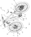
- Fig. 1 shows an isometric illustration of an embodiment of the bicycle 100 according to the invention, comprising a bicycle frame 1 and an embodiment of the incremental measuring path system 300 according to the invention.
- a front fork 2 which carries a front wheel 3, is arranged on the bicycle frame 1 in a steering head region 20.
- a brake disk 90 comprising a signaling means 210 and in particular a measuring ring 92, which will be described in more detail below, and is part of an incremental measuring path system.
- a rear wheel 6 is arranged on the bicycle frame 1 and is positioned on a dropout 8.
- the dropout 8 is part of the bicycle frame 1, wherein it is connected in a known manner to the seat stays 5 and chain stays 7.
- the bicycle frame 1 comprises a drive bearing area 24, on which a drive bearing housing for accommodating a battery-operated auxiliary motor 28 is formed.
- the auxiliary motor 28 can be, for example, an electric motor and in particular an electric motor with a crank drive.
- the bicycle frame 1 also includes a frame tube 10 which runs between the steering head region 20 and the drive bearing region 24.
- the frame tube 10 can be referred to as a down tube. It optionally runs in an inclined design from a steering head region 20 arranged at the front at the top in relation to the longitudinal plane of the bicycle and essentially one engine bearing area arranged in the lower center.
- the frame tube 10 is designed such that a battery is located in its interior and a battery receiving section 14 running axially there. can be inserted in particular for the auxiliary drive 28.
- the battery receptacle section 14 is equipped with an insertion opening 18 running on the end face 16, through which the front end of the battery can be inserted into the battery receptacle section.
- the bicycle frame 1 comprises a first embodiment of the incremental measuring path system, with at least one measuring ring 92 arranged here, for example on the front wheel 3, as part of the incremental path measuring system, for example for a tachometer unit. It is conceivable to also or alternatively arrange this measuring path system and in particular the measuring ring in the area of the rear wheel.
- the first embodiment of the incremental path measuring system shown comprises the signaling means 210 or the measuring ring 92 and a sensor means 96 operating with it.
- a measuring system and in particular the measuring ring 92, here attached to a brake disk 90 by way of example, not only for the bicycle 100 according to the invention, but can be applied to any type of bicycle.
- the measuring ring 92 is optionally formed or fastened on the brake disk 90 shown here.
- the measuring ring 92 is optionally designed to be rotationally symmetrical with respect to an axis Ax, which in the assembled state is arranged on the front bicycle tire 3 co-axially with the mounting axis (not shown).
- the measuring ring 92 has a plurality of signal transmitters, here in the form of knife elevations 94, which protrude from the measuring ring 92 in the form of features and optionally in the assembled state (see Fig. 1 ) point in the direction of a sensor means 96 or rotate past it at a smaller distance than its borders 93. It is optionally also possible to form the elevations in a direction pointing away from the sensor means 96, so that the borders 93, the elevations 94 running all the way around, rotate are on the sensor means 96 as the elevations.
- the sensor means is designed to detect the elevations 94 or, in the other embodiment mentioned above, the borders 93 as they rotate past the measuring sensor 96. It is known from the prior art to provide such an incremental measuring path system by means of a measuring ring, in which the measuring ring has cutouts and the measurement sensor detects these cutouts or the webs between the cutouts. However, such a measuring system is prone to errors; it was a matter of improving it.
- the incremental measuring path system now presented comprising the measuring ring 92 and the elevations 94 formed thereon, provides a much better and more reliable system.
- At least one elevation 94 is made larger or smaller than the remaining elevations. It therefore provides a calibration element 98, which can in particular prevent manipulation of the measurement results.
- a correspondingly assigned trigger unit for example on the speedometer 99 of the bicycle (see for example Fig. 1 )
- a measuring method can be initiated in which the revolutions of the measuring ring 92 are counted on the basis of the passage of the calibration element 98. This makes it difficult to manipulate the speed measurement system.
- an incremental travel measuring system and in particular the measuring ring 92 have a particular advantage.
- the larger configuration of at least one elevation 94 or of the calibration element 98 relates here optionally to the length in the circumferential direction, that is to say the length which runs past the sensor means during the rotation.
- the calibration element 98 is longer than the remaining elevations 94 when viewed in the circumferential direction and in particular by at least 5%, further optionally by at least 10% longer.
- the 5 to 9 show a second embodiment of the incremental measuring path system according to the invention or the signaling means 210 for such.
- the measurement path system 300 are attached to a bicycle 100 in order to determine a rotational speed of the wheel 3 of the bicycle 100 relative to a fixed point on the bicycle 100, for example the fork 2 and / or a frame 1 or another part of the bicycle.
- the incremental measuring path system likewise comprises at least one signaling means 210 with a plurality of, optionally in one signaling level Es (see Fig. 6 ) arranged signal transmitters 212 and at least one sensor means 96 cooperating with these signal transmitters 212.
- the signal transmitter means 210 can be arranged on the wheel 3 and the sensor means on the fixed point 2 or vice versa such that when the wheel 3 rotates, the signal transmitters 212 for scanning at least one signal path 214 , 218, in particular on the signal generators, and formation of at least one measurement signal that can be tapped past the sensor element 96 (viewed relatively).
- the signal paths are exemplary in the 7 to 9 shown.
- a measurement signal is generated which is optionally wired or wireless to a controller 302 (see Fig. 1 ) can be sent and evaluated there. In this way, for example, a rotational speed of the wheel can be determined.
- a controller 302 see Fig. 1
- a rotational speed of the wheel can be determined.
- the movement of the wheel itself can also be detected via such a measuring path system. All detection methods known from the prior art can be used here.
- At least one signal generator 212 and optionally exactly one signal generator is designed as a calibration element 98, comprising at least one signal path 218 which is designed differently from the signal paths 214 of the other signal generators 212.
- the signal path 218 of the calibration element 98 is longer than the other signal paths 214.
- Sensor element 96 is shown in FIGS 5 and 6 illustrated as an example; the 7 to 9 show an example of an embodiment of the signaling means 210 used.
- this signaling means 210 is designed as a measuring ring 92. It is possible to design this measuring ring 92 as a completely circumferential ring, but it can also be used only as a ring Partial ring be formed.
- the signal generator base in a brake disk 90 (see Fig. 1 ) to integrate.
- the auto switch base 92 can also be attached to a brake disc.
- At least one signal transmitter 212 and preferably all signal transmitters 212 and the sensor element 96 are designed as proximity switches. This means that the signal transmitter and sensor element have a proximity switch and in particular a proximity switch as has already been described above.
- each signal path 214 can be of the same length as the other signal paths 214, while the signal path 218 is shorter or longer.
- the other coding options described above can be used.
- the signaling means 210 has a preferred direction of rotation R, which is optionally selected here counterclockwise.
- This direction of rotation relates to a mounting side of the signaling device on the left-hand side of a bicycle, it relates on the left-hand side to the direction of travel of the Of the bicycle.
- the direction of rotation is preferably selected in the opposite direction.
- Each signaling means 212 optionally has a leading edge 220 and at least one trailing edge 230, the leading edge 220 defining the start of the signal path 214, 218 and the trailing edge 230 defining the end of the signal path 214, 218 of the signal generator. This is for example in the Fig. 5 . 8 and 9 shown.
- a so-called ramp-up signal is optionally generated, which defines the start of the signal path.
- a ramp-down signal is optionally generated which signals the end of the signal path 214, 218.
- the signal generator is understood as the space between the leading edge and the trailing edge of a detected signal path.
- each signal generator 212 has at least one elevation 94 protruding from the plane Es of the signal generator base 92.
- This elevation optionally has a plateau elevation, in particular at least one plateau surface 215 coplanar with the level of the signal transmitter base 92.
- the elevations 94 point in a direction pointing toward the sensor means 96.
- the elevations are optionally also opaque here.
- the signal generators or elevations 94 are embossed into the signal generator base 92 or the measuring ring 92 or the like is introduced plastically to deform the material, in particular by means of an embossing method.
- the elevations 94 emerge from the border 93 of the signal generator base 92.
- the resulting shapes of the leading edges 220 and trailing edges 230 are exemplary in section according to Fig. 9 shown. Because of the deformation process used, the edges 220, 230 are rounded here.
- the respective signal transmitters 212 in addition to the leading edges 220 and the trailing edges 230, are defined by longitudinal sides 240 are.
- these longitudinal sides 240 are optionally formed in an arc shape, the arc optionally running as a circular arc radially to the center point of the axis of rotation Ax.
- the signal transmitters 212 are connected both to their leading edges 220 and the trailing edges 230 and to the longitudinal sides 240 of the signal transmitter base 92 or the borders 93.
- the leading edge 220 and / or the trailing edge 230 in the signal transmitter level Es viewed in the form of a straight line. As in Fig. 5 these straight lines are shown in the signal transmitter level. It is optionally viewed in the radial direction of the wheel, arranged pivoted by a draft angle of ⁇ > 5 °, optionally ⁇ > 10 °.
- the leading edge and / or the trailing edge are designed to be inclined forward in the direction of rotation by this draft angle ⁇ .
- the 10 to 14 show a further embodiment of the incremental measuring path system according to the invention and in particular a further embodiment of the signal transmitter means 210 according to the invention.
- the signal transmitter means 210 corresponds essentially to the previously described signal transmitter means, but it has different signal transmitters 212 from it. Although the signal transmitters 212 are also designed here as elevations 94, they have leading and trailing edges 220, 230 of different design.
- leading edge 220 and / or at least one trailing edge 230 are optionally bent out of the signal generator base 92, punched out or cut into the like. It is also possible, especially in the 13 and 14 shown that these edges are not connected at least in sections to the signal generator base 92.
- leading edge 220 and / or the trailing edge 230 in the signal transmitter level Es are optionally formed as straight lines.
- the leading edge 220 and / or the trailing edge 230 adjoin an end wall 250, which is in one of the signal transmitter level Es and / or the signal transmitter base 92 deviating and in particular orthogonal to the plane. This is also in the 13 and 14 recognizable.
- the distance between the respective ramp-up signals is optionally found to be the same, while a distance between one ramp-down signal and the other ramp-down signals is different, or vice versa.
- This different distance is due to the calibration element 98 and its different signal path 218. This different calibration element reliably prevents manipulation of the signaling means 210.
- the 15 to 16 show a third embodiment of the invention incremental measuring path system or a further embodiment of the signaling device 212 according to the invention.
- This embodiment is almost identical to the previously described third embodiment, but here the signaling devices with their leading edges 220 and trailing edges 230 are designed differently warped with respect to the radial direction.
- the leading edge 220 and / or the trailing edge 230 is arranged in the signal transmitter level, viewed in the radial direction of the wheel, tilted backward by a draft angle ⁇ > 5 ° and optionally ⁇ > 10 °.
- Such an embodiment has proven to be particularly advantageous for determining an accurate detection signal.
- the invention also includes a method for producing a signaling device for an incremental measuring path system, as described here, comprising the following steps: providing a signaling device base and in particular a measuring ring; Forming and in particular stamping a plurality of signal transmitters into the signal transmitter base, each comprising at least one signal path which can be scanned by a sensor element, at least one signal generator, optionally exactly one signal generator, being designed as a calibration element, comprising at least one signal path which differs from the signal paths of the other signal generators is trained.
- the method optionally includes all other features, as previously described in relation to the bicycle, the incremental measuring path system or the signaling means. For reasons of redundancy, it is not explicitly dealt with here individually, but reference is made to the fact that these features can be transferred to the aforementioned method in the form of process steps and the production of such features. The reverse also applies, of course.
Landscapes
- Engineering & Computer Science (AREA)
- Mechanical Engineering (AREA)
- Physics & Mathematics (AREA)
- General Physics & Mathematics (AREA)
- Chemical & Material Sciences (AREA)
- Combustion & Propulsion (AREA)
- Transportation (AREA)
- Transmission And Conversion Of Sensor Element Output (AREA)
Priority Applications (1)
| Application Number | Priority Date | Filing Date | Title |
|---|---|---|---|
| EP19184336.6A EP3590812B1 (fr) | 2018-07-05 | 2019-07-04 | Système de mesure incrémental pour une bicyclette, bicyclette, moyen émetteur de signal et procédé de fabrication |
Applications Claiming Priority (3)
| Application Number | Priority Date | Filing Date | Title |
|---|---|---|---|
| EP18181933.5A EP3590813B1 (fr) | 2018-07-05 | 2018-07-05 | Bicyclette pourvue d'un entraînement auxiliaire fonctionnant sur batterie et cadre de bicyclette correspondant |
| EP18182236.2A EP3590814B1 (fr) | 2018-07-05 | 2018-07-06 | Bicyclette pourvue d'un entraînement auxiliaire fonctionnant sur batterie et cadre de bicyclette correspondant |
| EP19184336.6A EP3590812B1 (fr) | 2018-07-05 | 2019-07-04 | Système de mesure incrémental pour une bicyclette, bicyclette, moyen émetteur de signal et procédé de fabrication |
Publications (2)
| Publication Number | Publication Date |
|---|---|
| EP3590812A1 true EP3590812A1 (fr) | 2020-01-08 |
| EP3590812B1 EP3590812B1 (fr) | 2022-09-07 |
Family
ID=74549864
Family Applications (1)
| Application Number | Title | Priority Date | Filing Date |
|---|---|---|---|
| EP19184336.6A Active EP3590812B1 (fr) | 2018-07-05 | 2019-07-04 | Système de mesure incrémental pour une bicyclette, bicyclette, moyen émetteur de signal et procédé de fabrication |
Country Status (1)
| Country | Link |
|---|---|
| EP (1) | EP3590812B1 (fr) |
Cited By (5)
| Publication number | Priority date | Publication date | Assignee | Title |
|---|---|---|---|---|
| CN113859417A (zh) * | 2020-06-30 | 2021-12-31 | 什拉姆有限责任公司 | 自行车的速度感测装置和系统 |
| DE102020127569B3 (de) | 2020-10-20 | 2022-04-21 | C & S GmbH Consulting und Services | Geschwindigkeitsmessgerät |
| DE102022202716A1 (de) | 2022-03-21 | 2023-08-03 | Zf Friedrichshafen Ag | Messringelement für ein Messsystem für ein Mikromobilitätsfahrzeug, Messsystem und Mikromobilitätsfahrzeug |
| DE202024105856U1 (de) | 2024-10-11 | 2024-11-13 | Zf Friedrichshafen Ag | Radeinheit für ein Fahrrad und Fahrrad |
| DE102024209919A1 (de) | 2024-10-11 | 2026-04-16 | Zf Friedrichshafen Ag | Radeinheit für ein Fahrrad und Fahrrad |
Citations (4)
| Publication number | Priority date | Publication date | Assignee | Title |
|---|---|---|---|---|
| FR2526953A1 (fr) * | 1982-05-11 | 1983-11-18 | Citroen Sa | Detecteur magnetique de la vitesse de rotation ou d'une position angulaire donnee d'un arbre tournant |
| WO2013046472A1 (fr) * | 2011-09-30 | 2013-04-04 | パイオニア株式会社 | Dispositif et procédé de détection d'angle de rotation |
| DE102015120656A1 (de) * | 2015-11-27 | 2017-06-01 | Gustav Magenwirth Gmbh & Co. Kg | Radeinheit |
| DE102017115157A1 (de) * | 2017-07-06 | 2019-01-10 | Saf-Holland Gmbh | Polrad |
-
2019
- 2019-07-04 EP EP19184336.6A patent/EP3590812B1/fr active Active
Patent Citations (4)
| Publication number | Priority date | Publication date | Assignee | Title |
|---|---|---|---|---|
| FR2526953A1 (fr) * | 1982-05-11 | 1983-11-18 | Citroen Sa | Detecteur magnetique de la vitesse de rotation ou d'une position angulaire donnee d'un arbre tournant |
| WO2013046472A1 (fr) * | 2011-09-30 | 2013-04-04 | パイオニア株式会社 | Dispositif et procédé de détection d'angle de rotation |
| DE102015120656A1 (de) * | 2015-11-27 | 2017-06-01 | Gustav Magenwirth Gmbh & Co. Kg | Radeinheit |
| DE102017115157A1 (de) * | 2017-07-06 | 2019-01-10 | Saf-Holland Gmbh | Polrad |
Cited By (11)
| Publication number | Priority date | Publication date | Assignee | Title |
|---|---|---|---|---|
| CN113859417A (zh) * | 2020-06-30 | 2021-12-31 | 什拉姆有限责任公司 | 自行车的速度感测装置和系统 |
| EP3939871A1 (fr) * | 2020-06-30 | 2022-01-19 | Sram, Llc | Dispositifs et systèmes de détection de vitesse pour bicyclette |
| CN113859417B (zh) * | 2020-06-30 | 2023-11-17 | 什拉姆有限责任公司 | 自行车的速度感测装置和系统 |
| TWI828335B (zh) * | 2020-06-30 | 2024-01-01 | 美商速聯有限責任公司 | 用於自行車之速度感測系統 |
| DE102020127569B3 (de) | 2020-10-20 | 2022-04-21 | C & S GmbH Consulting und Services | Geschwindigkeitsmessgerät |
| DE102022202716A1 (de) | 2022-03-21 | 2023-08-03 | Zf Friedrichshafen Ag | Messringelement für ein Messsystem für ein Mikromobilitätsfahrzeug, Messsystem und Mikromobilitätsfahrzeug |
| WO2023180138A1 (fr) | 2022-03-21 | 2023-09-28 | Zf Friedrichshafen Ag | Élément annulaire de mesure pour un système de mesure pour un véhicule de micromobilité, système de mesure et véhicule de micromobilité |
| EP4535010A2 (fr) | 2022-03-21 | 2025-04-09 | ZF Friedrichshafen AG | Élément annulaire de mesure pour un système de mesure pour un câble électronique, système de mesure et câble électronique |
| EP4535010A3 (fr) * | 2022-03-21 | 2025-06-25 | ZF Friedrichshafen AG | Élément annulaire de mesure pour un système de mesure pour un câble électronique, système de mesure et câble électronique |
| DE202024105856U1 (de) | 2024-10-11 | 2024-11-13 | Zf Friedrichshafen Ag | Radeinheit für ein Fahrrad und Fahrrad |
| DE102024209919A1 (de) | 2024-10-11 | 2026-04-16 | Zf Friedrichshafen Ag | Radeinheit für ein Fahrrad und Fahrrad |
Also Published As
| Publication number | Publication date |
|---|---|
| EP3590812B1 (fr) | 2022-09-07 |
Similar Documents
| Publication | Publication Date | Title |
|---|---|---|
| EP3590812B1 (fr) | Système de mesure incrémental pour une bicyclette, bicyclette, moyen émetteur de signal et procédé de fabrication | |
| DE10057468B4 (de) | Drehmomenterfassungssystem | |
| EP1902288B1 (fr) | Dispositif capteur pour saisir un angle differentiel | |
| DE69411657T2 (de) | Kodierelement mit Messaufnehmer und damit angestattetem Lager | |
| DE102017207716B4 (de) | Lenkeinrichtung | |
| EP3073622B1 (fr) | Moteur électrique commuté électroniquement par balayage direct du champ magnétique de rotor | |
| DE19900330A1 (de) | Drehwinkelsensor, Drehmomentsensor mit einem Drehwinkelsensor und Servo-Lenkvorrichtung, die einen derartigen Drehmomentsensor verwendet | |
| WO2013186001A1 (fr) | Bague magnétique d'un système de détection de position de rotor d'un moteur électrique électriquement commuté | |
| DE102015102013A1 (de) | Sensorvorrichtung mit einer Drehmomentsensoreinrichtung und einer Inkrementalsensoreinrichtung und Kraftfahrzeug mit einer solchen Sensorvorrichtung | |
| DE112007000289T5 (de) | Elektrische Servolenkungsvorrichtung | |
| DE102019124973A1 (de) | Sensoranordnung zur Erfassung eines Lenkmomentes sowie einer absoluten Winkelposition und Sensorvorrichtung mit dieser Sensoranordnung | |
| DE3410736A1 (de) | Analoger wegsensor | |
| DE202018103775U1 (de) | Leistungsmessanordnung | |
| WO2010060851A2 (fr) | Dispositif de détection pour mesurer le couple de rotation dans des systèmes de direction | |
| DE69524366T2 (de) | Wälzlager mit Drehgeschwindigkeitssensor | |
| DE10137400A1 (de) | Rotationserfassungsvorrichtung | |
| EP3884241B1 (fr) | Codeur de mesure pour arbre d'escalator | |
| DE60006520T2 (de) | Vorrichtung zur rückführung in die totlage insbesondere für steuerräder | |
| DE102011055893A1 (de) | Lenksystem in einem Fahrzeug | |
| DE4425398A1 (de) | Druckerfassungsgerät | |
| DE102014014391A1 (de) | Kombiniertes Sensorkonzept für Lenksysteme von Kraftfahrzeugen | |
| DE102020101937A1 (de) | Schutzhülse für einen Drehzahlsensor | |
| DE102011084191A1 (de) | Lenkanordnung | |
| EP1312534A2 (fr) | Dispositif pour la détermination de l'angle de braquage d'un volant | |
| DE212010000224U1 (de) | Detektor zum Erfassen der Drehrichtung einer Achse, insbesondere einer Fahrradpedalachse |
Legal Events
| Date | Code | Title | Description |
|---|---|---|---|
| PUAI | Public reference made under article 153(3) epc to a published international application that has entered the european phase |
Free format text: ORIGINAL CODE: 0009012 |
|
| STAA | Information on the status of an ep patent application or granted ep patent |
Free format text: STATUS: THE APPLICATION HAS BEEN PUBLISHED |
|
| AK | Designated contracting states |
Kind code of ref document: A1 Designated state(s): AL AT BE BG CH CY CZ DE DK EE ES FI FR GB GR HR HU IE IS IT LI LT LU LV MC MK MT NL NO PL PT RO RS SE SI SK SM TR |
|
| AX | Request for extension of the european patent |
Extension state: BA ME |
|
| STAA | Information on the status of an ep patent application or granted ep patent |
Free format text: STATUS: REQUEST FOR EXAMINATION WAS MADE |
|
| 17P | Request for examination filed |
Effective date: 20200608 |
|
| RBV | Designated contracting states (corrected) |
Designated state(s): AL AT BE BG CH CY CZ DE DK EE ES FI FR GB GR HR HU IE IS IT LI LT LU LV MC MK MT NL NO PL PT RO RS SE SI SK SM TR |
|
| STAA | Information on the status of an ep patent application or granted ep patent |
Free format text: STATUS: EXAMINATION IS IN PROGRESS |
|
| 17Q | First examination report despatched |
Effective date: 20200918 |
|
| RIC1 | Information provided on ipc code assigned before grant |
Ipc: B62L 1/00 20060101ALN20220317BHEP Ipc: G01P 21/02 20060101ALI20220317BHEP Ipc: G01P 3/481 20060101ALI20220317BHEP Ipc: B62J 45/423 20200101ALI20220317BHEP Ipc: B62J 45/413 20200101ALI20220317BHEP Ipc: B62M 6/50 20100101AFI20220317BHEP |
|
| GRAP | Despatch of communication of intention to grant a patent |
Free format text: ORIGINAL CODE: EPIDOSNIGR1 |
|
| STAA | Information on the status of an ep patent application or granted ep patent |
Free format text: STATUS: GRANT OF PATENT IS INTENDED |
|
| INTG | Intention to grant announced |
Effective date: 20220503 |
|
| GRAS | Grant fee paid |
Free format text: ORIGINAL CODE: EPIDOSNIGR3 |
|
| GRAA | (expected) grant |
Free format text: ORIGINAL CODE: 0009210 |
|
| STAA | Information on the status of an ep patent application or granted ep patent |
Free format text: STATUS: THE PATENT HAS BEEN GRANTED |
|
| AK | Designated contracting states |
Kind code of ref document: B1 Designated state(s): AL AT BE BG CH CY CZ DE DK EE ES FI FR GB GR HR HU IE IS IT LI LT LU LV MC MK MT NL NO PL PT RO RS SE SI SK SM TR |
|
| REG | Reference to a national code |
Ref country code: GB Ref legal event code: FG4D Free format text: NOT ENGLISH |
|
| REG | Reference to a national code |
Ref country code: CH Ref legal event code: EP Ref country code: AT Ref legal event code: REF Ref document number: 1516842 Country of ref document: AT Kind code of ref document: T Effective date: 20220915 |
|
| REG | Reference to a national code |
Ref country code: DE Ref legal event code: R096 Ref document number: 502019005538 Country of ref document: DE |
|
| REG | Reference to a national code |
Ref country code: IE Ref legal event code: FG4D Free format text: LANGUAGE OF EP DOCUMENT: GERMAN |
|
| REG | Reference to a national code |
Ref country code: NL Ref legal event code: FP |
|
| REG | Reference to a national code |
Ref country code: LT Ref legal event code: MG9D |
|
| PG25 | Lapsed in a contracting state [announced via postgrant information from national office to epo] |
Ref country code: SE Free format text: LAPSE BECAUSE OF FAILURE TO SUBMIT A TRANSLATION OF THE DESCRIPTION OR TO PAY THE FEE WITHIN THE PRESCRIBED TIME-LIMIT Effective date: 20220907 Ref country code: RS Free format text: LAPSE BECAUSE OF FAILURE TO SUBMIT A TRANSLATION OF THE DESCRIPTION OR TO PAY THE FEE WITHIN THE PRESCRIBED TIME-LIMIT Effective date: 20220907 Ref country code: NO Free format text: LAPSE BECAUSE OF FAILURE TO SUBMIT A TRANSLATION OF THE DESCRIPTION OR TO PAY THE FEE WITHIN THE PRESCRIBED TIME-LIMIT Effective date: 20221207 Ref country code: LV Free format text: LAPSE BECAUSE OF FAILURE TO SUBMIT A TRANSLATION OF THE DESCRIPTION OR TO PAY THE FEE WITHIN THE PRESCRIBED TIME-LIMIT Effective date: 20220907 Ref country code: LT Free format text: LAPSE BECAUSE OF FAILURE TO SUBMIT A TRANSLATION OF THE DESCRIPTION OR TO PAY THE FEE WITHIN THE PRESCRIBED TIME-LIMIT Effective date: 20220907 Ref country code: FI Free format text: LAPSE BECAUSE OF FAILURE TO SUBMIT A TRANSLATION OF THE DESCRIPTION OR TO PAY THE FEE WITHIN THE PRESCRIBED TIME-LIMIT Effective date: 20220907 |
|
| PG25 | Lapsed in a contracting state [announced via postgrant information from national office to epo] |
Ref country code: HR Free format text: LAPSE BECAUSE OF FAILURE TO SUBMIT A TRANSLATION OF THE DESCRIPTION OR TO PAY THE FEE WITHIN THE PRESCRIBED TIME-LIMIT Effective date: 20220907 Ref country code: GR Free format text: LAPSE BECAUSE OF FAILURE TO SUBMIT A TRANSLATION OF THE DESCRIPTION OR TO PAY THE FEE WITHIN THE PRESCRIBED TIME-LIMIT Effective date: 20221208 |
|
| PG25 | Lapsed in a contracting state [announced via postgrant information from national office to epo] |
Ref country code: SM Free format text: LAPSE BECAUSE OF FAILURE TO SUBMIT A TRANSLATION OF THE DESCRIPTION OR TO PAY THE FEE WITHIN THE PRESCRIBED TIME-LIMIT Effective date: 20220907 Ref country code: RO Free format text: LAPSE BECAUSE OF FAILURE TO SUBMIT A TRANSLATION OF THE DESCRIPTION OR TO PAY THE FEE WITHIN THE PRESCRIBED TIME-LIMIT Effective date: 20220907 Ref country code: PT Free format text: LAPSE BECAUSE OF FAILURE TO SUBMIT A TRANSLATION OF THE DESCRIPTION OR TO PAY THE FEE WITHIN THE PRESCRIBED TIME-LIMIT Effective date: 20230109 Ref country code: ES Free format text: LAPSE BECAUSE OF FAILURE TO SUBMIT A TRANSLATION OF THE DESCRIPTION OR TO PAY THE FEE WITHIN THE PRESCRIBED TIME-LIMIT Effective date: 20220907 Ref country code: CZ Free format text: LAPSE BECAUSE OF FAILURE TO SUBMIT A TRANSLATION OF THE DESCRIPTION OR TO PAY THE FEE WITHIN THE PRESCRIBED TIME-LIMIT Effective date: 20220907 |
|
| PG25 | Lapsed in a contracting state [announced via postgrant information from national office to epo] |
Ref country code: SK Free format text: LAPSE BECAUSE OF FAILURE TO SUBMIT A TRANSLATION OF THE DESCRIPTION OR TO PAY THE FEE WITHIN THE PRESCRIBED TIME-LIMIT Effective date: 20220907 Ref country code: PL Free format text: LAPSE BECAUSE OF FAILURE TO SUBMIT A TRANSLATION OF THE DESCRIPTION OR TO PAY THE FEE WITHIN THE PRESCRIBED TIME-LIMIT Effective date: 20220907 Ref country code: IS Free format text: LAPSE BECAUSE OF FAILURE TO SUBMIT A TRANSLATION OF THE DESCRIPTION OR TO PAY THE FEE WITHIN THE PRESCRIBED TIME-LIMIT Effective date: 20230107 Ref country code: EE Free format text: LAPSE BECAUSE OF FAILURE TO SUBMIT A TRANSLATION OF THE DESCRIPTION OR TO PAY THE FEE WITHIN THE PRESCRIBED TIME-LIMIT Effective date: 20220907 |
|
| REG | Reference to a national code |
Ref country code: DE Ref legal event code: R097 Ref document number: 502019005538 Country of ref document: DE |
|
| P01 | Opt-out of the competence of the unified patent court (upc) registered |
Effective date: 20230522 |
|
| PG25 | Lapsed in a contracting state [announced via postgrant information from national office to epo] |
Ref country code: AL Free format text: LAPSE BECAUSE OF FAILURE TO SUBMIT A TRANSLATION OF THE DESCRIPTION OR TO PAY THE FEE WITHIN THE PRESCRIBED TIME-LIMIT Effective date: 20220907 |
|
| PLBE | No opposition filed within time limit |
Free format text: ORIGINAL CODE: 0009261 |
|
| STAA | Information on the status of an ep patent application or granted ep patent |
Free format text: STATUS: NO OPPOSITION FILED WITHIN TIME LIMIT |
|
| PG25 | Lapsed in a contracting state [announced via postgrant information from national office to epo] |
Ref country code: DK Free format text: LAPSE BECAUSE OF FAILURE TO SUBMIT A TRANSLATION OF THE DESCRIPTION OR TO PAY THE FEE WITHIN THE PRESCRIBED TIME-LIMIT Effective date: 20220907 |
|
| 26N | No opposition filed |
Effective date: 20230608 |
|
| PG25 | Lapsed in a contracting state [announced via postgrant information from national office to epo] |
Ref country code: SI Free format text: LAPSE BECAUSE OF FAILURE TO SUBMIT A TRANSLATION OF THE DESCRIPTION OR TO PAY THE FEE WITHIN THE PRESCRIBED TIME-LIMIT Effective date: 20220907 |
|
| PG25 | Lapsed in a contracting state [announced via postgrant information from national office to epo] |
Ref country code: MC Free format text: LAPSE BECAUSE OF FAILURE TO SUBMIT A TRANSLATION OF THE DESCRIPTION OR TO PAY THE FEE WITHIN THE PRESCRIBED TIME-LIMIT Effective date: 20220907 |
|
| PG25 | Lapsed in a contracting state [announced via postgrant information from national office to epo] |
Ref country code: MC Free format text: LAPSE BECAUSE OF FAILURE TO SUBMIT A TRANSLATION OF THE DESCRIPTION OR TO PAY THE FEE WITHIN THE PRESCRIBED TIME-LIMIT Effective date: 20220907 |
|
| REG | Reference to a national code |
Ref country code: CH Ref legal event code: PL |
|
| REG | Reference to a national code |
Ref country code: BE Ref legal event code: MM Effective date: 20230731 |
|
| PG25 | Lapsed in a contracting state [announced via postgrant information from national office to epo] |
Ref country code: LU Free format text: LAPSE BECAUSE OF NON-PAYMENT OF DUE FEES Effective date: 20230704 |
|
| GBPC | Gb: european patent ceased through non-payment of renewal fee |
Effective date: 20230704 |
|
| PG25 | Lapsed in a contracting state [announced via postgrant information from national office to epo] |
Ref country code: LU Free format text: LAPSE BECAUSE OF NON-PAYMENT OF DUE FEES Effective date: 20230704 |
|
| REG | Reference to a national code |
Ref country code: IE Ref legal event code: MM4A |
|
| PG25 | Lapsed in a contracting state [announced via postgrant information from national office to epo] |
Ref country code: GB Free format text: LAPSE BECAUSE OF NON-PAYMENT OF DUE FEES Effective date: 20230704 Ref country code: CH Free format text: LAPSE BECAUSE OF NON-PAYMENT OF DUE FEES Effective date: 20230731 |
|
| PG25 | Lapsed in a contracting state [announced via postgrant information from national office to epo] |
Ref country code: IT Free format text: LAPSE BECAUSE OF FAILURE TO SUBMIT A TRANSLATION OF THE DESCRIPTION OR TO PAY THE FEE WITHIN THE PRESCRIBED TIME-LIMIT Effective date: 20220907 Ref country code: BE Free format text: LAPSE BECAUSE OF NON-PAYMENT OF DUE FEES Effective date: 20230731 |
|
| PG25 | Lapsed in a contracting state [announced via postgrant information from national office to epo] |
Ref country code: IE Free format text: LAPSE BECAUSE OF NON-PAYMENT OF DUE FEES Effective date: 20230704 |
|
| PG25 | Lapsed in a contracting state [announced via postgrant information from national office to epo] |
Ref country code: IE Free format text: LAPSE BECAUSE OF NON-PAYMENT OF DUE FEES Effective date: 20230704 |
|
| PG25 | Lapsed in a contracting state [announced via postgrant information from national office to epo] |
Ref country code: BG Free format text: LAPSE BECAUSE OF FAILURE TO SUBMIT A TRANSLATION OF THE DESCRIPTION OR TO PAY THE FEE WITHIN THE PRESCRIBED TIME-LIMIT Effective date: 20220907 |
|
| PG25 | Lapsed in a contracting state [announced via postgrant information from national office to epo] |
Ref country code: BG Free format text: LAPSE BECAUSE OF FAILURE TO SUBMIT A TRANSLATION OF THE DESCRIPTION OR TO PAY THE FEE WITHIN THE PRESCRIBED TIME-LIMIT Effective date: 20220907 |
|
| PG25 | Lapsed in a contracting state [announced via postgrant information from national office to epo] |
Ref country code: CY Free format text: LAPSE BECAUSE OF FAILURE TO SUBMIT A TRANSLATION OF THE DESCRIPTION OR TO PAY THE FEE WITHIN THE PRESCRIBED TIME-LIMIT; INVALID AB INITIO Effective date: 20190704 |
|
| PG25 | Lapsed in a contracting state [announced via postgrant information from national office to epo] |
Ref country code: HU Free format text: LAPSE BECAUSE OF FAILURE TO SUBMIT A TRANSLATION OF THE DESCRIPTION OR TO PAY THE FEE WITHIN THE PRESCRIBED TIME-LIMIT; INVALID AB INITIO Effective date: 20190704 |
|
| REG | Reference to a national code |
Ref country code: AT Ref legal event code: MM01 Ref document number: 1516842 Country of ref document: AT Kind code of ref document: T Effective date: 20240704 |
|
| PG25 | Lapsed in a contracting state [announced via postgrant information from national office to epo] |
Ref country code: AT Free format text: LAPSE BECAUSE OF NON-PAYMENT OF DUE FEES Effective date: 20240704 |
|
| PG25 | Lapsed in a contracting state [announced via postgrant information from national office to epo] |
Ref country code: TR Free format text: LAPSE BECAUSE OF FAILURE TO SUBMIT A TRANSLATION OF THE DESCRIPTION OR TO PAY THE FEE WITHIN THE PRESCRIBED TIME-LIMIT Effective date: 20220907 |
|
| PGFP | Annual fee paid to national office [announced via postgrant information from national office to epo] |
Ref country code: NL Payment date: 20251230 Year of fee payment: 7 Ref country code: FR Payment date: 20251230 Year of fee payment: 7 |
|
| PGFP | Annual fee paid to national office [announced via postgrant information from national office to epo] |
Ref country code: DE Payment date: 20251230 Year of fee payment: 7 |
|
| PGFP | Annual fee paid to national office [announced via postgrant information from national office to epo] |
Ref country code: AT Payment date: 20260410 Year of fee payment: 5 |