EP3884800B1 - Article chaussant et système de charge - Google Patents
Article chaussant et système de charge Download PDFInfo
- Publication number
- EP3884800B1 EP3884800B1 EP21160296.6A EP21160296A EP3884800B1 EP 3884800 B1 EP3884800 B1 EP 3884800B1 EP 21160296 A EP21160296 A EP 21160296A EP 3884800 B1 EP3884800 B1 EP 3884800B1
- Authority
- EP
- European Patent Office
- Prior art keywords
- article
- footwear
- charging
- component
- charging device
- Prior art date
- Legal status (The legal status is an assumption and is not a legal conclusion. Google has not performed a legal analysis and makes no representation as to the accuracy of the status listed.)
- Active
Links
Images






Classifications
-
- A—HUMAN NECESSITIES
- A43—FOOTWEAR
- A43C—FASTENINGS OR ATTACHMENTS OF FOOTWEAR; LACES IN GENERAL
- A43C11/00—Other fastenings specially adapted for shoes
- A43C11/16—Fastenings secured by wire, bolts, or the like
- A43C11/165—Fastenings secured by wire, bolts, or the like characterised by a spool, reel or pulley for winding up cables, laces or straps by rotation
-
- A—HUMAN NECESSITIES
- A43—FOOTWEAR
- A43B—CHARACTERISTIC FEATURES OF FOOTWEAR; PARTS OF FOOTWEAR
- A43B1/00—Footwear characterised by the material
- A43B1/0054—Footwear characterised by the material provided with magnets, magnetic parts or magnetic substances
-
- A—HUMAN NECESSITIES
- A43—FOOTWEAR
- A43B—CHARACTERISTIC FEATURES OF FOOTWEAR; PARTS OF FOOTWEAR
- A43B3/00—Footwear characterised by the shape or the use
- A43B3/34—Footwear characterised by the shape or the use with electrical or electronic arrangements
-
- A—HUMAN NECESSITIES
- A43—FOOTWEAR
- A43B—CHARACTERISTIC FEATURES OF FOOTWEAR; PARTS OF FOOTWEAR
- A43B3/00—Footwear characterised by the shape or the use
- A43B3/34—Footwear characterised by the shape or the use with electrical or electronic arrangements
- A43B3/36—Footwear characterised by the shape or the use with electrical or electronic arrangements with light sources
-
- A—HUMAN NECESSITIES
- A43—FOOTWEAR
- A43C—FASTENINGS OR ATTACHMENTS OF FOOTWEAR; LACES IN GENERAL
- A43C1/00—Shoe lacing fastenings
-
- A—HUMAN NECESSITIES
- A43—FOOTWEAR
- A43C—FASTENINGS OR ATTACHMENTS OF FOOTWEAR; LACES IN GENERAL
- A43C11/00—Other fastenings specially adapted for shoes
- A43C11/008—Combined fastenings, e.g. to accelerate undoing or fastening
-
- H—ELECTRICITY
- H02—GENERATION; CONVERSION OR DISTRIBUTION OF ELECTRIC POWER
- H02J—ELECTRIC POWER NETWORKS; CIRCUIT ARRANGEMENTS OR SYSTEMS FOR SUPPLYING OR DISTRIBUTING ELECTRIC POWER; SYSTEMS FOR STORING ELECTRIC ENERGY
- H02J50/00—Circuit arrangements or systems for wireless supply or distribution of electric power
- H02J50/10—Circuit arrangements or systems for wireless supply or distribution of electric power using inductive coupling
-
- H—ELECTRICITY
- H02—GENERATION; CONVERSION OR DISTRIBUTION OF ELECTRIC POWER
- H02J—ELECTRIC POWER NETWORKS; CIRCUIT ARRANGEMENTS OR SYSTEMS FOR SUPPLYING OR DISTRIBUTING ELECTRIC POWER; SYSTEMS FOR STORING ELECTRIC ENERGY
- H02J7/00—Circuit arrangements for charging or discharging batteries or for supplying loads from batteries
- H02J7/70—Circuit arrangements for charging or discharging batteries or for supplying loads from batteries characterised by the mechanical construction
Definitions
- the present disclosure is directed to a method of controlling an article of footwear including an upper, a sole structure, an interior cavity, an automated tensioning system, a battery, a charging assembly, and a sensor.
- the method comprises receiving information from the sensor, where the sensor is configured to detect a connection of the charging assembly with an external charging device, and detecting if the charging assembly is connected to the external charging device.
- the method also includes automatically loosening the article of footwear through an operation of the automated tensioning system if the sensor determines that the charging assembly is connected to the external charging device.
- the present disclosure is directed to a kit of parts for making an article of footwear in accordance with either of the previous aspects.
- the kit of parts includes an article of footwear with an upper, a sole structure, an interior cavity, an automated tensioning system, a battery, a charging assembly, and a first sensor.
- the external charging device is configured to connect with the charging assembly in order to charge the battery of the article of footwear, and the charging assembly includes a ferromagnetic material, such that the charging assembly can magnetically couple with the external charging device to hold the charging assembly and the external charging device together.
- longitudinal refers to a direction extending a length of a component.
- a longitudinal direction of an article of footwear extends between a forefoot region and a heel region of the article of footwear.
- forward is used to refer to the general direction in which the toes of a foot point, and the term “rearward” is used to refer to the opposite direction, i.e., the direction in which the heel of the foot is facing.
- lateral direction refers to a side-to-side direction extending a width of a component.
- the lateral direction may extend between a medial side and a lateral side of an article of footwear, with the lateral side of the article of footwear being the surface that faces away from the other foot, and the medial side being the surface that faces toward the other foot.
- vertical refers to a direction generally perpendicular to both the lateral and longitudinal directions. For example, in cases where a sole is planted flat on a ground surface, the vertical direction may extend from the ground surface upward. It will be understood that each of these directional adjectives may be applied to individual components of a sole.
- upward refers to the vertical direction heading away from a ground surface, while the term “downward” refers to the vertical direction heading toward the ground surface.
- top refers to the portion of an object substantially furthest from the ground in a vertical direction
- bottom refers to the portion of an object substantially closest to the ground in a vertical direction
- the "interior” of a shoe refers to space that is occupied by a wearer's foot when the shoe is worn.
- the “inner side” of a panel or other shoe element refers to the face of that panel or element that is (or will be) oriented toward the shoe interior in a completed shoe.
- the “outer side” or “exterior” of an element refers to the face of that element that is (or will be) oriented away from the shoe interior in the completed shoe.
- the inner side of an element may have other elements between that inner side and the interior in the completed shoe.
- an outer side of an element may have other elements between that outer side and the space external to the completed shoe.
- the terms “inward” and “inwardly” shall refer to the direction toward the interior of the shoe, and the terms “outward” and “outwardly” shall refer to the direction toward the exterior of the shoe.
- the foregoing directional terms when used in reference to an article of footwear, shall refer to the article of footwear when sitting in an upright position, with the sole facing groundward, that is, as it would be positioned when worn by a wearer standing on a substantially level surface.
- fixedly attached shall refer to two components joined in a manner such that the components may not be readily separated (for example, without destroying one or both of the components).
- exemplary modalities of fixed attachment may include joining with permanent adhesive, rivets, stitches, nails, staples, welding or other thermal bonding, or other joining techniques.
- two components may be "fixedly attached” by virtue of being integrally formed, for example, in a molding process.
- removable attachment shall refer to the joining of two components or a component and an element in a manner such that the two components are secured together, but may be readily detached from one another.
- removable attachment mechanisms may include hook and loop fasteners, friction fit connections, interference fit connections, magnetic connections, threaded connectors, cam-locking connectors, compression of one material with another, and other such readily detachable connectors.
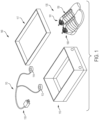
- FIG. 1 illustrates an embodiment of a footwear charging system (“charging system”) 140.
- charging system 140 may be a kit of parts in some embodiments.
- the kit of parts may include a container 115 configured to store components of charging system 140.
- charging system 140 may include a complementary pair of footwear (“pair") 135, comprising a first article of footwear ("first article”) 100 and a second article of footwear (“second article) 101.
- first article first article
- second article second article
- a complementary pair of footwear refers to two articles of footwear that are designed to be worn as a pair by one user on a right foot and a left foot.
- the kit of parts comprising charging system 140 may be separate from complementary pair of footwear 135.
- charging system 140 may be manufactured or configured separately from complementary pair of footwear 135.
- charging system 140 may be utilized with a different pair of footwear.
- charging system 140 may further include an external charging unit (“charging unit”) 110.
- charging unit 110 can include multiple components for connecting or contacting to various elements.
- charging unit 110 includes a first charging component (“first component”) 112 and a second charging component (“second component”) 114. In other embodiments, there may be only one charging component, or there may be additional charging components.
- charging unit 110 of charging system 140 can include provisions for receiving power from an external power source of some kind.
- charging unit 110 can include a power cord 118 that is configured to receive power from an external power source.
- power cord 118 can be plugged into a wall socket.
- Power cord 118 can comprise a plug and cord (or cable) in some embodiments.
- power cord 118 may be configured for use in a wide range of environments.
- power cord 118 may be connected to a standard AC power source or outlet (i.e., sockets) in some embodiments.
- power cord 118 may connect with a 110-volt power supply.
- power cord 118 may be configured for utilization with a range of voltages, including 110, 115, 120, 220, 230, or other standard residential voltages, and/or DC power. In some cases, power cord 118 may be adapted for industrial voltage use. Thus, charging unit 110 may be readily used in most of the locations where charging unit 110 may be transported or used. Charging unit 110 will be discussed further below with respect to FIG. 3 .
- container 115 may be configured to contain or store complementary pair of footwear 135 as well as charging unit 110 that comprises charging system 140.
- container 115 may be a box, such as a traditional shoebox or plastic resealable container, with a lid 117 or cover.
- container 115 is illustrated here with a particular design.
- container 115 is illustrated as a generally three-dimensional rectangular shoebox.
- container 115 can comprise any type of housing with the capacity for storing articles of footwear.
- container 115 can comprise a bag that resembles a traditional duffle-type bag.
- container 115 could be sized to fit a single pair of footwear, a single article of footwear, or multiple pairs of footwear, as well as other portions of charging system 140, in different embodiments. In other embodiments, however, container 115 could have any other design. In particular, container 115 could have another shape and/or size in other embodiments. Examples of other designs for a container include, but are not limited to, any type of box, receptacle, housing, platform, bags, and/or backpacks. Furthermore, the container could include any provisions for carrying the container, including any type of strap or handle. In embodiments including charging system 140, container 115 can include provisions for storing various systems or components associated with an article or charging component. In particular, in embodiments including an inductive charging system (see further below), container 115 can provide or be configured to hold or secure components of the inductive charging system that allow power to be transferred from an external power source to complementary pair of footwear 135.
- one or more parts of charging system 140 can include provisions for indicating the status of the charging system during use.
- one or both articles of footwear comprising complementary pair of footwear 135 can include a visual indicator, such as a light, for indicating the charging status.
- charging unit 110 can include a visual indicator, or can include a sound-based indicator, such as a speaker configured to produce a sound to indicate the charging status.
- charging indicators may be LED lights that are lit to indicate the charging status of an article of footwear in some embodiments. For example, if first article 100 is being charged alone, only one light associated with first article 100 may be lit.
- both a first light associated with first article 100 and a second light associated with second article 101 may be lit.
- the color of one or both charging indicators and/or any sounds may change depending on the status of the charging system.
- charging indicators may be disposed along any portion of charging system 140. However, in other embodiments, such as those illustrated herein, there may be no charging indicators included in charging system 140.
- first article 100 may also be applicable to second article 101, including directional adjectives and the identification of general components (e.g., a sole structure and an upper) comprising each article.
- first article 100 and second article 101 may include some differences in structure and/or design depending on the desired use or function of pair 135.
- first article 100 is shown in the form of an athletic shoe, such as a running shoe.
- tensioning system 150 may be used with any other kind of footwear including, but not limited to, hiking boots, soccer shoes, football shoes, sneakers, running shoes, cross-training shoes, rugby shoes, basketball shoes, baseball shoes as well as other kinds of shoes.
- tensioning system 150 may be configured for use with various kinds of non-sports-related footwear, including, but not limited to, slippers, sandals, high-heeled footwear, loafers as well as any other kinds of footwear.
- a tensioning system may not be limited to footwear, and in other embodiments, a tensioning system and/or components associated with a tensioning system could be used with various kinds of apparel, including clothing, sportswear, sporting equipment, and other kinds of apparel. In still other embodiments, a tensioning system may be used with braces, such as medical braces.
- first article 100 may be divided into three general regions along a longitudinal axis 180: a forefoot region 105, a midfoot region 125, and a heel region 145.
- Forefoot region 105 generally includes portions of first article 100 corresponding with the toes and the joints connecting the metatarsals with the phalanges.
- Midfoot region 125 generally includes portions of first article 100 corresponding with an arch area of the foot.
- Heel region 145 generally corresponds with rear portions of the foot, including the calcaneus bone.
- Forefoot region 105, midfoot region 125, and heel region 145 are not intended to demarcate precise areas of first article 100. Rather, forefoot region 105, midfoot region 125, and heel region 145 are intended to represent general relative areas of first article 100 to aid in the following discussion. Since various features of first article 100 extend beyond one region of first article 100, the terms forefoot region 105, midfoot region 125, and heel region 145 apply not only to first article 100 but also to the various elements or components comprising first article 100.
- upper 102 may include one or more material elements (for example, meshes, textiles, foam, leather, and synthetic leather), which may be joined to define an interior void configured to receive a foot of a wearer.
- the material elements may be selected and arranged to selectively impart properties such as light weight, durability, air permeability, wear resistance, flexibility, and comfort.
- Upper 102 may define an opening 130 through which a foot of a wearer may be received into the interior void.
- sole structure 104 may be fixedly attached to upper 102 (for example, with adhesive, stitching, welding, or other suitable techniques) and may have a configuration that extends between upper 102 and the ground.
- Sole structure 104 may include provisions for attenuating ground reaction forces (that is, cushioning and stabilizing the foot during vertical and horizontal loading).
- sole structure 104 may be configured to provide traction, impart stability, and control or limit various foot motions, such as pronation, supination, or other motions.
- sole structure 104 may be configured to provide traction for first article 100. In addition to providing traction, sole structure 104 may attenuate ground reaction forces when compressed between the foot and the ground during walking, running, or other ambulatory activities.
- the configuration of sole structure 104 may vary significantly in different embodiments to include a variety of conventional or non-conventional structures. In some cases, the configuration of sole structure 104 can be configured according to one or more types of ground surfaces on which sole structure 104 may be used.
- the disclosed concepts may be applicable to footwear configured for use on any of a variety of surfaces, including indoor surfaces or outdoor surfaces.
- the configuration of sole structure 104 may vary based on the properties and conditions of the surfaces on which first article 100 is anticipated to be used. For example, sole structure 104 may vary depending on whether the surface is harder or softer. In addition, sole structure 104 may be tailored for use in wet or dry conditions.
- sole structure 104 may be configured for a particularly specialized surface or condition.
- the proposed footwear upper construction may be applicable to any kind of footwear, such as basketball, soccer, football, and other athletic activities. Accordingly, in some embodiments, sole structure 104 may be configured to provide traction and stability on hard indoor surfaces (such as hardwood), soft, natural turf surfaces, or on hard, artificial turf surfaces. In some embodiments, sole structure 104 may be configured for use on multiple different surfaces.
- sole structure 104 may include different components.
- sole structure 104 may include multiple components, which may individually or collectively provide first article 100 with a number of attributes, such as support, rigidity, flexibility, stability, cushioning, comfort, reduced weight, or other attributes.
- sole structure 104 may include an insole/sockliner, a cushioning layer, a midsole, and an outer sole member ("outsole") 162, which may have an exposed, ground-contacting lower surface. In some cases, however, one or more of these components may be omitted.
- sole structure 104 may comprise a sole plate 161, as will be further discussed below.
- an insole may be disposed in the void defined by upper 102.
- the insole may extend through each of forefoot region 105, midfoot region 125, and heel region 145, and between lateral side 185 and medial side 165 of first article 100.
- the insole may be formed of a deformable (for example, compressible) material, such as polyurethane foams, or other polymer foam materials. Accordingly, the insole may, by virtue of its compressibility, provide cushioning, and may also conform to the foot in order to provide comfort, support, and stability.
- a midsole 151 may be fixedly attached to a lower area of upper 102 (for example, through stitching, adhesive bonding, thermal bonding (such as welding), or other techniques), or may be integral with upper 102.
- Midsole 151 may be formed from any suitable material having the properties described above, according to the activity for which first article 100 is intended.
- midsole 151 may include a foamed polymer material, such as polyurethane (PU), ethyl vinyl acetate (EVA), or any other suitable material that operates to attenuate ground reaction forces as sole structure 104 contacts the ground during walking, running, or other ambulatory activities.
- PU polyurethane
- EVA ethyl vinyl acetate
- materials can be adjusted to provide greater resilience and structural support.
- first article 100 may include a tongue 172, which may be provided near or along a throat opening 132.
- tongue 172 may be provided in or near an instep region of first article 100.
- tongue 172 may be disposed along other portions of an article of footwear, or an article may not include a tongue.
- sole structure 104 can include one or more cleat members or traction elements that are configured to increase traction with a ground surface.
- lacing guides 154 in the figures is only intended to be exemplary, and it will be understood that other embodiments are not limited to a particular configuration for lacing guides 154. Furthermore, the particular types of lacing guides 154 illustrated in the embodiments are also exemplary, and other embodiments may incorporate any other kinds of lacing guides or similar lacing provisions. In some other embodiments, for example, laces could be inserted through traditional eyelets. Some examples of lace guiding provisions that may be incorporated into the embodiments are disclosed in Cotterman et al., U.S. Patent Application Publication Number 2012/0000091, published January 5, 2012 and entitled "Lace Guide,". Additional examples are disclosed in Goodman et al., U.S.
- a motorized tensioning device may generally be configured to automatically apply tension to a lace for purposes of tightening and loosening upper 102.
- a motorized tensioning device may thus include provisions for winding a lace onto, and unwinding a lace from, a spool internal to the motorized tensioning device.
- the provisions may include an electric motor that automatically winds and unwinds the spool in response to various inputs or controls.
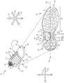
- a bottom view 250 of first article 100 is also depicted near first article 100.
- Bottom view 250 includes a magnified view of outsole 162 and sole plate 161.
- Sole structure 104 includes outsole 162 joined to midsole 151, where midsole 151 is joined to or is disposed adjacent to sole plate 161.
- outsole 162 may include a shape and size substantially similar to that of at least a portion of midsole 151.
- outsole 162 extends over and covers a large portion of midsole 151.
- outsole 162 may comprise a different shape or size.
- outsole 162 may cover a smaller portion of midsole 151 than depicted here.
- outsole 162 may be substantially larger than midsole 151.
- bridge portion 204 can be disposed further toward one side versus another side.
- bridge portion 204 is arranged such that it is disposed along medial side 165 of sole structure 104.
- central longitudinal axis 280 represents a longitudinal midline of midsole 151
- bridge portion 204 may be laterally offset with respect to central longitudinal axis 280.
- bridge portion 204 may be disposed more centrally and/or extend across both sides of sole structure 104.
- sole plate 161 may be at least partially exposed in the assembled sole structure.
- an underside 200 of sole plate 161 as shown herein can include one or more exposed regions.
- sole plate 161 includes two exposed regions, here referred to as a first region 230 and a second region 240.
- housing 272 can include an internal charging device 274 that may facilitate the charging of tensioning system 150 in first article 100.
- internal charging device 274 can be linked to or otherwise connected to an external charging system (such as charging unit 110 of FIG. 1 ) to transfer power to a battery associated with first article 100.
- internal charging device 274 can comprise internal inductive loops that can be charged by an inductive charging system.
- housing 272 can optionally include a securing element that can facilitate the connection of an external charging component with sole structure 104 (see FIGS. 8-10 ).
- the sensors providing information might include, but are not limited to, pressure sensors in shoe insoles to detect standing and/or rate of motion, bend indicators, strain gauges, gyroscopes, and accelerometers.
- the sensor information may be used to establish a new target tension.
- pressure sensors could be used to measure contact pressures of the upper of an article of footwear against the foot of a wearer and automatically adjust to achieve a desired pressure.
- housing 272 may include a sensor in some embodiments.
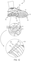
- a sensor may detect and measure a relative change with respect to a connection that is created between charging assembly 270 and a component of the charging system.
- the use of the term "connect” or "connection” in the context of the charging system, charging assembly and/or charging unit should be understood to mean a link that occurs between two devices or components that facilitates access or communication of a transfer of power or information related to the charging process. The link may occur as a result of the physical contact between two surfaces, but it may also be created through wireless signals or signals that do not require physical contact.
- the use of sensors will be discussed further with respect to FIGS. 11 and 12 .
- first article 100 can be configured for use with an external charging unit.
- the dimensions of the exposed regions of sole plate 161 may facilitate a connection with an external charging unit.
- sole structure 104 can include a recess 276 that is dimensioned to receive a portion of an external charging unit in different embodiments.
- recess 276 can be formed or defined by portions of the surfaces of underside 200 of sole plate 161, outsole 162, and midsole 151.
- Recess 276 can have a first volume that is configured to receive, enclose, contain, or otherwise hold a portion of another device or component, as will be discussed further below.
- the height of recess 276 can vary.
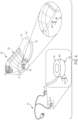
- charging system 140 may include charging unit 110 comprising first component 112 and second component 114.
- charging unit 110 may facilitate the transfer of power to one or more articles of footwear.
- charging unit 110 may comprise a charging station and be configured to provide the functions of a charging system, as described above with respect to FIG. 1 .
- charging unit 110 may include provisions for transferring power to one or more articles of footwear.
- a charging unit can include a central processing unit (CPU) of some kind.
- a charging unit could comprise a simple circuit of some kind for receiving electrical inputs and providing an electrical output according to the inputs.
- a charging unit may include a printed circuit board.
- a charging unit may include a number of ports that facilitate the input and output of information and power.
- the term "port" means any interface or shared boundary between two conductors for purposes of this disclosure.
- ports can facilitate the insertion and removal of conductors. Examples of these types of ports include mechanical connectors.
- ports are interfaces that generally do not provide easy insertion or removal. Examples of these types of ports include soldering or electron traces on circuit boards.
- the charging unit can include one or more ports configured to transfer power to an external inductive loop. It should be understood that the reference to an external inductive loop is with respect to an inductive loop that is external to an article of footwear.
- an external inductive loop may be enclosed or housed within a structure.
- an external inductive loop can be disposed within a portion of first component 112 and/or second component 114, or some other portion of charging system 140.
- an external inductive loop may be associated with an internal inductive loop of a corresponding article of footwear.
- external charging unit 110 that is utilized in charging system 140 may be configured for use with first article 100.
- charging unit 110 can include components that are dimensioned to be connected to first article 100.
- one or more components of charging unit 110 can be dimensioned to be received by a portion of sole structure 104 (see FIG. 2 ).
- a component can be dimensioned to fit or be received by recess 276 in sole structure 104 (see FIG. 2 ).
- first component 112. For purposes of illustration, the discussion herein will focus on first component 112. However, it should be understood that features and descriptions provided regarding first component 112 may be generally applicable to second component 114 in some embodiments. To better illustrate an embodiment of first component 112 for the reader, an isometric magnified view 300 of first component 112 is included in FIG. 3 .
- First component 112 may have a housing structure that can comprise different shapes in different embodiments.
- first component 112 may comprise a generally cylindrical geometry, including a top portion 302 associated with a top side, and a base portion 304 associated with a bottom side, as well as a continuous, curved surface 306 extending between top portion 302 and base portion 304.
- Top portion 302 and base portion 304 are depicted as generally circular in FIG. 3 .
- the dimensions and/or shape of top portion 302, base portion 304, and/or curved surface 306 may differ, including but not limited to oblong, triangular, square, rectangular, oval, elliptical, or other regular or irregular shapes.
- first component 112 can have a spherical, prism, cone, pyramidal, cuboid, or other regular or irregular geometry.
- the geometry of first component 112 or the shapes of one or more of its surfaces may be configured to correspond or match with a portion of first article 100, as will be discussed further below.
- first component 112 may be smooth or generally untextured surfaces. However, in other embodiments, some surfaces can exhibit textures or other surface characteristics, such as dimpling, protrusions, ribs, ridges, securing elements, nubs, or various patterns, for example.
- first component 112 can include one or more locating or structural features to facilitate alignment of first component 112 within charging system 140. In particular, in embodiments using an inductive charging system, it may be necessary to ensure proper alignment of internal inductive loops disposed within each article with any external inductive loops disposed in charging unit 110.
- top portion 302 can be configured with recesses that engage protrusions located on bottom surfaces of first region 230 of sole plate 161 (see FIG. 2 ). In other cases, top portion 302 can be configured with protrusions that engage recesses located on bottom surfaces of first region 230 of sole plate 161 (see FIG. 2 ). In still other embodiments, other types of locating features that are known in the art can be used. With these arrangements, an article can be maintained in a predetermined location with respect to first component 112. In particular, articles may be positioned in a manner that orients any internal inductive loops with any external inductive loops disposed within first component 112. However, in some embodiments, top portion 302 does not include locating features, and may be substantially smooth or flat.
- top portion 302 has a third area 333 defined by a substantially round perimeter (or circumference).
- base portion 30 may have a substantially similar area to top portion 302.
- top portion 302 may have a different sized area than base portion 304.
- first component 112 may include a second volume that can be substantially similar to or less that the first volume of recess 276 (shown in FIG. 2 ) in different embodiments.
- the second volume of first component 112 may be the same or smaller than the first volume associated with recess 276 of sole plate 161 in FIG. 2 . In some embodiments, this can allow first component 112 to be disposed fully within the space bounded by recess 276, as will be discussed in FIGS. 5-7 .
- first component 112 may include different elements in various embodiments.
- first component 112 (which comprises the housing that is generally defined by the various outer surfaces that have been described above) can encase one or more inductive loops, circuitry, wiring, or other charging components.
- first component 112 can include a region or component that has a greater degree of magnetic attraction, such as a ferromagnetic material that can be disposed along the outer surface of first component 112, or in the interior of first component 112.
- top portion 302 and base portion 304 comprise substantially similar materials. In other embodiments, top portion 302 and base portion 304 can differ. For example, top portion 302 may include a region configured to improve or facilitate a connection to a sole structure. In addition, in one embodiment, base portion 304 may be generally smooth and/or flat. However, in other embodiments, base portion 304 may comprise undulations or bumps, or other types of texturing. In some cases, there may be traction elements disposed along base portion 304 to help anchor or secure first component 112, for example. Thus, in some embodiments, base portion 304 can include provisions for stability or grip on a ground surface.
- the current embodiment generally describes an external inductive loop disposed in first component 112 of charging unit 110
- other embodiments can include external inductive loops disposed in other portions of charging unit 110.
- the current embodiment includes internal inductive loops disposed in a sole structure of an article of footwear
- an internal inductive loop could be disposed in any other portion of an article of footwear. Examples of other portions that could house an internal inductive loop include, but are not limited to, a tongue, an upper sidewall, a forefoot portion of an upper, a heel portion of an upper, as well as any other portion of an article of footwear.
- the location of an internal inductive loop in an article of footwear can be selected according to the location of an external inductive loop in a charging unit so that the internal inductive loop can be readily arranged adjacent to the external inductive loop when the article is inserted onto or placed adjacent to the charging unit, allowing inductive coupling (i.e., charging in an inductive based charging system) to occur.
- first component 112 can comprise different plastics, polymers, thermoplastic polyurethane (TPU), nylon, glass, carbon fiber, carbon composites, or other types of materials.
- portions of a charging component may comprise a light-diffusive material.
- charging unit 110 can include power cord 118 that is configured to receive power from an external power source.
- first component 112 and/or second component 114 of charging unit 110 may be connected with, integral with, or fixedly attached to a first cable line 350 that is part of power cord 118, as shown in FIG. 3 .
- first component 112 can contact, link, join, or be otherwise attached to first cable line 350.
- first component 112 can include a port that connects first component 112 with first cable line 350.
- the various portions of power cord 118 may comprise different lengths, dimensions, materials, and configurations, including any cables or cords known in the art.
- power cord 118 can comprise a Y-type cable, as shown in FIG. 3 .
- first cable line 350 extending from first component 112 and a second cable line 352 extending from second component 114.
- First cable line 350 and second cable line 352 can join at a central region 354, and extend toward a power adaptor 360 along a central cable line 356.
- first component 112 and second component 114 may be configured to be moved or arranged independently of one another.
- first component 112 can be utilized by an article of footwear without a concurrent use of second component 114, for example.
- first component 112 and recess 276 may have dimensions that complement each other and facilitate the connection of first component 112 with charging assembly 270.
- recess 276 can have a first volume that is greater than or substantially similar to the second volume of first component 112; similarly, first region 230 of recess 276 can have first area 233 that is greater to or substantially similar to third area 333 (see FIGS. 2 and 3 ).
- first component 112 has a thickness 410 that extends between top portion 302 and base portion 304. Thickness 410 also generally corresponds to the width of curved surface 306 in FIG. 4 .
- recess 276 in sole structure 104 has a height 420. As shown in FIG. 4 , in one embodiment, thickness 410 may be less than height 420. This difference in thickness can facilitate the link or association between first component 112 and an article of footwear in some embodiments, as will be discussed below. However, in other embodiments, thickness 410 may be substantially similar to height 420 or larger than height 420.
- thickness 410 may be generally consistent throughout first component 112, and height 420 may be generally consistent throughout recess 276. However, in other embodiments, there may be irregularities throughout first component 112 and/or sole structure 104, such that the thicknesses or height are not consistent. For example, in embodiments where first component 112 includes ridges or other irregularities along top portion 302, there may be corresponding irregularities in the thickness of first component. In such cases, thickness 410 may be understood to represent the maximum thickness of first component 410.
- the upper surface of recess 276 (associated with the underside of sole plate 161 in first region 230, as shown in FIG. 2 ) may be spaced apart from top portion 302 of first component 112, such that there is no physical contact between the two surfaces. In other embodiments, due to the close or substantially similar value of height 420 and thickness 410, the upper surface of recess 276 may contact or press against the surface of top portion 302 of first component 112.
- first article 100 can include midsole 151 and outsole 162.
- midsole 151 can be disposed adjacent to sole plate 161.
- Sole plate 161 includes a portion along midfoot region 125 that is an exposed outer surface (associated with first region 230 and second region 240 of FIG. 2 ).
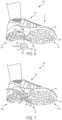
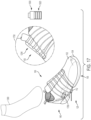
- first article 100 has a first recess 576 and second article 101 has a second recess 578, which are each substantially similar to recess 276 discussed previously with respect to FIGS. 2-4 .
- the charging system described herein may differ in other ways.
- the charging system of the present disclosure may include features of charging systems disclosed in Beers et al., U.S. Patent Number 8,058,837, issued November 15, 2011 (previously U.S. Patent Application No. 12/369,410, filed February 11, 2009 ) and entitled "Charging System for an Article of Footwear,".
- charging unit 110 may be configured for use with pair 135.
- first component 112 and first article 100 For purposes of illustration, the discussion herein will focus on first component 112 and first article 100. However, it should be understood that features and descriptions provided regarding first component 112 and first article 100 (as well as components associated with first article 100) may be generally applicable to second component 114 and second article 101 in different embodiments.
- first component 112 is mounted or installed.
- a portion of the exposed surface of first region 230 of sole plate 161 can be positioned such that it is disposed adjacent to top portion 302 of first component 112.
- first component 112 can be received by recess 276 such that a portion of curved surface 306 can press or contact a side surface 676 of midsole 151.
- the curvature of curved surface 306 may be substantially similar to the curvature of side surface 676 and improve the fit between the surfaces.
- each article can be maintained in a predetermined location with respect to its charging units during charging, which is especially beneficial in embodiments that incorporate an inductive charging system.
- first component 112 and first article 100 there may be additional provisions included in some embodiments.
- various types of securing elements may be incorporated in article 100. Some of the embodiments disclosed herein may include one or more securing elements that can facilitate the connection between an article of footwear and a charging unit.
- securing element(s) may comprise a magnetic fastener or magnetic securing system.
- there may be magnetic materials incorporated into one or both of the articles of footwear and the charging unit.
- the magnetic materials can correspond in position to the desired placement or positioning of the charging component relative to the sole structure.
- inductive loops disposed in first article 100 can be positioned to facilitate the charging of components if an inductive charging system is being used.
- charging system 140 may include provisions to facilitate the alignment of internal inductive loops disposed within each article with any external inductive loops disposed in the charging unit.
- "magnetic securing elements" can be utilized to help ensure the proper position of the charging component with the exposed surface of the sole structure comprising charging assembly 270.
- the charging component(s) and/or any associated magnets can be coated with a water-insulating material like rubber to protect it from everyday use in which an article of footwear may be dirty or covered with residual particles.
- the charging component(s) and magnetic portions can undergo oxidation to provide a water-insulating layer on the component.
- the size and/or weight of a magnetic securing element as discussed with respect to second element 820 should be such that it does not make the charging component too heavy but is nevertheless sufficiently strong in terms of its magnetic power so as to enable the charging component to be readily attracted to the article of footwear.
- the magnetic attraction should be sufficient so that as a user subsequently removes his or her foot from the article of footwear, the connection is not displaced or interrupted (unless that is the intention of the user).
- Attractive magnetic field 850 is schematically represented by a series of rings surrounding the illustration of first component 112 in FIGS. 8-10 .
- attractive magnetic field 850 may draw both portions toward one another, and/or generate a pulling force. Once the two portions are brought close enough to one another, the two elements can be pulled and held together securely by an attractive force, allowing for a magnetic connective force.
- the magnetic connection is supplemented by different securing mechanisms, which can securely fix first element 810 alongside second element 820.
- first element 810 and second element 820 may not directly (i.e., physically) contact one another in some embodiments, they may nevertheless be securely and removably attached to one another through the proximity of first article 100 to first component 112.
- a user may facilitate the coupling by stepping or moving toward charging component 112 while wearing first article 100, as shown in FIGS. 8-10 .
- unlaced state 1204 represents a specific condition in which the article of footwear is fully unlaced (as loose as the system is configured to allow the article to become).
- unlaced state 1204 may also represent a level of tension in which the system recognizes that the article of footwear is loosened to a particular level of tension or tightness that is preset by the system or desired by the user.
- unlaced state 1204 need not only represent the "fully unlaced" condition of the article of footwear, and may also be associated with a minimal amount of tension of the lacing system.
- laced state 1102 can represent a specific condition in which the system recognizes that the article of footwear is fully laced (as tightly as the system has been configured to allow the article to become). However, in some cases, laced state 1102 may also represent a condition in which the system recognizes that the article of footwear is laced to a particular level of tension or tightness that is desired by the user or preset by the system. In other words, laced state 1102 need not represent the "fully laced" condition of the article of footwear, and may also be associated with only a minimal amount of tension of the lacing system. However, laced state 1102 is understood to be a greater tension level than unlaced state 1204. In some embodiments, laced state 1102 can comprise all levels of tension associated with the automated tensioning system that are greater than the tension level of unlaced state unlaced state 1204.
- first sensor 1100 may be disposed in an article of footwear.
- first sensor 1100 can comprise a component that detects changes in magnetic forces, changes in infrared radiation, microwaves, or ultrasonics, contact with a particular surface, and/or proximity to another component.
- first sensor 1100 can include a capacitive sensor or capacitive displacement sensor, a sensor based on the Doppler effect, an inductive sensor, an optical sensor, radar, sonar, or a fiber optics sensor.
- Other embodiments may include any type of sensors that can detect a connection between two components.
- first sensor 1100 is not engaged or activated.
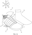
- first article 100 is shown in laced state 1102 (see a first lacing region view 1150).
- first sensor 1100 can become activated in some embodiments.
- the engagement of first sensor 1100 can initiate a series of events in the article of footwear and lead to a change in the state of automated tensioning system 150.
- the activation or engagement of first sensor 1100 initiates a process whereby first article 100 can transition from laced state 1102 (see FIG.
- first sensor 1100 may inform tensioning system 150 that first article 100 is now connected to a charging device, and an auto-unlacing process (depicted in FIG. 12 with arrows) of first article 100 should occur.
- first article 100 can be connected to the charging unit.
- first article 100 can charge while foot 1300 is removed from first article 100.
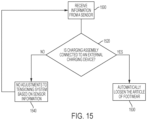
- FIG. 15 provides a flow chart depicting one process of controlling an article of footwear, where the article of footwear includes an upper, a sole structure, an interior cavity, an automated tensioning system, a battery, a charging assembly, and a sensor.
- the article of footwear can receive information from a sensor in a first step 1500.
- the method of controlling the article of footwear can include a second step 1510 of determining whether the charging assembly is connected to the external charging device.
- a third step 1530 can comprise automatically loosening the article of footwear through an operation of the automated tensioning system if the sensor determines that the charging assembly is connected to the external charging device.
- a fourth step 1540 comprises making no adjustments to the tensioning system based on the sensor information if the sensor does not determine that the charging assembly is connected to the external charging device.
- one article or a pair of footwear can be charged and then removed to permit the charging of additional (different) pairs of footwear with the same charging unit.
- additional embodiments can further comprise the step of determining if the battery is charged.
- an additional step can comprise determining if a foot is disposed in the interior cavity of the article of footwear.
- another step can include automatically tightening the article of footwear through an operation of the automated tensioning system if the battery is charged and a foot is disposed in the interior cavity.
- Additional embodiments can comprise inductively charging the article of footwear when the charging assembly is connected to the external charging device.
- second step 1510 of detecting a connection also includes determining if magnetic coupling has occurred between the charging assembly and the external charging device.
- third step 1530 of automatically loosening the article of footwear can further include the step of instructing the automated tensioning system to loosen the article of footwear.
- the external charging unit may include provisions for charging a battery or other power source associated with the article of footwear.
- FIG. 16 is one embodiment of the charging process with respect to first article 100.
- the battery associated with first article 100 may be charged.
- the energy level of a battery 1600 may increase over time.
- battery 1600 of first article 100 is nearly depleted at the time of the connection, as shown with a first energy level 1610.
- battery 1600 can be in any other energy state or have any other energy level.
- first article 100 remains in unlaced state 1204 during the charging process.
- the amount of tension of the article of footwear during charging can vary from that depicted here.
- battery 1600 is sufficiently charged (for example, the energy level of battery 1600 is above a certain operating threshold, or battery 1600 is fully charged), as shown with a second energy level 1620, the article may be configured for normal operations.
- a user may return to first article 100 following a duration of time sufficient to charge the battery for use in normal operation. This duration may vary widely, as, for example, the energy level of the battery can vary at the time the connection between first article 100 and first component 112 occurs, or the battery model or type may differ in different embodiments. In other embodiments, other features may be configured differently in different embodiments, such that the time required to charge the battery is variable.
- first article 100 remains connected to charging unit 110.
- first article 100 may be first disconnected from the corresponding charging unit before foot 1300 is inserted.
- different states or functions of the automated tensioning system may be triggered by the activation of a sensor.
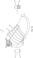
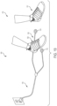
- an autolacing process may be initiated by the activation of a second sensor 1700 located in the article of footwear.
- the sensor can detect changes in pressure.
- second sensor 1700 may detect and measure a relative change in a force or applied load, detect and measure the rate of change in force, identify force thresholds, and/or detect contact and/or touch.
- the sensor may comprise a generally two-dimensional material.
- second sensor 1700 may include a piezoelectric material.
- second sensor 1700 may have different dimensions and/or shapes in different embodiments and be disposed in other regions or portions of first article 100 than shown here.
- the application of pressure (for example, of a foot being inserted into first article 100) can activate second sensor 1700, which in turn can trigger other events, such as autolacing.
- second sensor 1700 can comprise a force sensitive resistor (FSR).
- FSR force sensitive resistor
- the FSR may be located along heel region 145 of first article 100.
- first article 100 Prior to the insertion of foot 1300, first article 100 may be in unlaced state 1204, as shown in third lacing region view 1750.
- second sensor 1700 when foot 1300 is fully inserted into first article 100, such that the heel of foot 1300 can apply pressure along heel region 145, second sensor 1700 (shown in FIG.
- second sensor 1700 can become activated in some embodiments.
- second sensor 1700 detects a predetermined or preset amount of pressure or weight (i.e., a force)
- second sensor 1700 becomes activated.
- the engagement of second sensor 1700 can initiate a series of events and/or cause a change in the state of the automated tensioning system.
- the activation or engagement of second sensor 1700 initiates a process whereby first article 100 can transition from unlaced state 1204 of FIG. 17 to laced state 1102 (shown in fourth lacing region view 1850 in FIG. 18 ).
- the engagement of second sensor 1700 may inform the system that article 100 is now being used or worn by a user, and that an autolacing process (represented by arrows in FIG. 18 ) may occur.
- the autolacing process moves the article to laced state 1102.
- automated tensioning system 150 may include provisions to automatically tighten one or more article of footwear.
- the automatic tightening is configured to occur once the article detects that a user has resumed the wearing of pair 135, and pair 135 is sufficiently charged for normal operations.
- the autolacing feature may facilitate the use of an article of footwear by allowing a user to rapidly and easily insert a foot into the article of footwear and be automatically fitted (i.e., whereby the tension level of the article is increased to a desired or preset setting) and ready for regular use.
- the autolacing process may occur only when the article remains connected to the charger unit and a foot is inserted into the article.
- the autolacing can occur when a foot is inserted into the article, regardless of whether the article is still connected to the charger unit.
- the insertion of a foot into the article of footwear does not necessarily trigger the autolacing process, and such an operation may be optional.
- a user may simply pull first article 100 away from charging component 112 until the pulling force exceeds the attractive magnetic force between first element 810 and second element 820 (see FIGS. 8-10 ).
- the system may include an additional device that can be adjusted or manipulated to "unlock" first article 100 from charging component 112.
- a pull tab such as a tensile element, a loop, or a hook that extends from a portion of first article 100 and can be grasped by a user and help release first article 100 from charging component 112.
- the charging system discussed in this detailed description and in the claims can be used independently of a tensioning system.
- the charging system discussed in this detailed description is used to charge a battery of some kind, that battery can be further coupled to one or more different electrical systems.
- the charging system discussed in this detailed description and in the claims may be used to power any type of electrical system associated with an article of footwear.
- the charging system discussed in this embodiment could be used to charge a battery to power an accelerometer or a sensor for tracking distance and motion.
- the charging system discussed here could be used to power a heating and/or cooling system for an article.
- the charging system could be used to power two or more electrical systems simultaneously.
- the embodiments of the external charging unit as described herein may be utilized with any type or configuration of footwear or article of apparel that have any type of system or mechanism.
- the charging unit need not be adjusted to accommodate different sizes of footwear.
- some or all portions of the charging system such as the charging unit, can retain their original shape and dimensions and be used with footwear ranging in size from a "child size" to an "adult size.”
- the charging system can be utilized with footwear ranging between U.S. standard size 6 and larger.
- the charging system could be used with footwear ranging from U.S. standard size 4 and 20.
- the charging system could be used with footwear ranging from U.S. standard child size 5 to a men's size 21 or larger.
Landscapes
- Engineering & Computer Science (AREA)
- Microelectronics & Electronic Packaging (AREA)
- Footwear And Its Accessory, Manufacturing Method And Apparatuses (AREA)
Claims (15)
- Article chaussant (100), l'article chaussant comprenant :une tige (102) et une structure de semelle (104) ;un système de tension automatisé (150) qui est configuré pour ajuster un niveau de tension de l'article chaussant d'un premier niveau de tension à un deuxième niveau de tension, dans lequel le premier niveau de tension est supérieur au deuxième niveau de tension ;un ensemble de charge (270) configuré pour se coupler magnétiquement avec un dispositif de charge externe, l'ensemble de charge comprenant :un dispositif de charge interne (274)un logement (272) ; etun matériau ferromagnétique (810), etun capteur (1100), agencé pour fournir des informations au système de tension automatisé lorsque l'ensemble de charge est connecté au dispositif de charge externe (110).
- Article chaussant (100) selon la revendication 1, dans lequel le deuxième niveau de tension correspond à un état ouvert de l'article chaussant ; et facultativement dans lequel le système de tension automatisé (150) est configuré pour desserrer l'article chaussant du premier niveau de tension au deuxième niveau de tension lorsque le système de tension automatisé reçoit des informations en provenance du capteur (1100) indiquant que l'ensemble de charge (270) est connecté au dispositif de charge externe (110).
- Article chaussant (100) selon l'une quelconque des revendications précédentes, dans lequel le dispositif de charge interne (274) est un dispositif de charge inductive qui est configuré pour se coupler par induction avec le dispositif de charge externe (110) ; facultativement dans lequel l'article chaussant inclut une batterie (1600) qui est chargée par le biais d'un processus de charge inductive ; et facultativement dans lequel le système de tension automatisé (150) est configurer pour resserrer l'article chaussant du deuxième niveau de tension au premier niveau de tension lorsque le système de tension automatisé reçoit des informations indiquant qu'un pied a été inséré dans une cavité intérieure de l'article chaussant et que la batterie a été chargée.
- Article chaussant (100) selon l'une quelconque des revendications précédentes, dans lequel l'ensemble de charge (270) inclut un composant attractif configuré pour renforcer le couplage magnétique entre l'ensemble de charge et le dispositif de charge externe (110).
- Article chaussant (100) selon l'une quelconque des revendications précédentes, dans lequel l'ensemble de charge (270) inclut un évidement de réception (276) configuré pour recevoir une portion du dispositif de charge externe (110) ; et facultativement dans lequel une hauteur de l'évidement de réception est supérieure à une hauteur du dispositif de charge externe.
- Procédé de commande d'un article chaussant (100) incluant une tige (102), une structure de semelle (104), une cavité intérieure, un système de tension automatisé (150), une batterie (1600), un ensemble de charge (270), et un capteur (1100) configuré pour détecter une connexion de l'ensemble de charge avec un dispositif de charge externe (110), le procédé comprenant :la réception d'informations en provenance du capteur ;la détection de si l'ensemble de charge est connecté au dispositif de charge externe, dans lequel l'étape consistant à détecter une connexion inclut la détermination de si un couplage magnétique s'est produit entre l'ensemble de charge et le dispositif de charge externe.
- Procédé selon la revendication 6, comprenant en outre :la détermination de si la batterie (1600) est chargée ;la détermination de si un pied est disposé dans la cavité intérieure de l'article chaussant (100) ; etle resserrage automatique de l'article chaussant par le biais d'une opération du système de tension automatisé (150) si la batterie est chargée et qu'un pied est disposé dans la cavité intérieure.
- Procédé selon la revendication 6 ou la revendication 7, comprenant en outre le desserrage automatique de l'article chaussant (100) par le biais d'une opération du système de tension automatisé (150) si le capteur (1100) détermine que l'ensemble de charge (270) est connecté au dispositif de charge externe (110) ; et facultativement dans lequel l'étape consistant à desserrer automatique de l'article chaussant inclut l'étape consistant à donner instruction au système de tension automatisé de desserrer l'article chaussant.
- Procédé selon l'une quelconque des revendications 6 à 8, comprenant en outre la charge inductive de l'article chaussant (100) lorsque l'ensemble de charge (270) est connecté au dispositif de charge externe (110).
- Kit de pièces pour fabriquer un article chaussant (100) selon l'une quelconque des revendications 1 à 5, le kit de pièces comprenant :
un article chaussant avec :une tige (102),une structure de semelle (104),une cavité intérieure,un système de tension automatisé (150),une batterie (1600),un ensemble de charge (270) incluant un matériau ferromagnétique (810), etun premier capteur, etun dispositif de charge externe (110) configuré pour se connecter avec l'ensemble de charge (270) afin de charger la batterie de l'article chaussantdans lequel l'ensemble de charge est configuré pour se coupler magnétiquement avec le dispositif de charge externe pour maintenir ensemble l'ensemble de charge et le dispositif de charge externe. - Kit de pièces selon la revendication 10, dans lequel le système de tension automatisé (270) est configuré pour ajuster un niveau de tension de l'article chaussant (100) d'un premier niveau de tension à un deuxième niveau de tension lorsque le premier capteur (1100) détecte une connexion entre l'ensemble de charge (270) et le dispositif de charge externe (110), et dans lequel le premier niveau de tension est supérieur au deuxième niveau de tension.
- Kit de pièces selon la revendication 10 ou la revendication 11, dans lequel l'article chaussant (100) inclut en outre un deuxième capteur (1700), dans lequel le système de tension automatisé (150) est configuré pour ajuster le niveau de tension de l'article chaussant du deuxième niveau de tension à un troisième niveau de tension lorsque le deuxième capteur détecte une insertion d'un pied dans la cavité intérieure de l'article chaussant et la batterie (1600) est chargée, et dans lequel le troisième niveau de tension est supérieur au deuxième niveau de tension.
- Kit de pièces selon l'une quelconque des revendications 10 à 12, dans lequel le dispositif de charge externe (110) inclut un premier composant (112), un deuxième composant (114), et un câble de type Y (118), le câble de type Y ayant une première extrémité, une deuxième extrémité, et une troisième extrémité, dans lequel la première extrémité du câble de type Y se connecte au premier composant, la deuxième extrémité du câble de type Y se connecte au deuxième composant, et la troisième extrémité du câble de type Y est configurée pour se connecter à une source d'alimentation externe ; et facultativement dans lequel l'ensemble de charge (270) est configuré pour se connecter avec le premier composant ou au deuxième composant.
- Kit de pièces selon la revendication 13, dans lequel l'ensemble de charge (270) inclut un évidement de réception (276) configuré pour recevoir le premier composant (112), et dans lequel une hauteur de l'évidement de réception est supérieure à une hauteur du premier composant.
- Kit de pièces selon la revendication 13 ou la revendication 14, dans lequel l'ensemble de charge (270) inclut un composant attractif configuré pour aider à assujettir l'article chaussant (100) au premier composant (112), et dans lequel le couplage magnétique entre l'ensemble de charge et le premier composant est configuré pour permettre à un utilisateur de retirer un pied de la cavité intérieure de l'article chaussant tandis que l'ensemble de charge est connecté au premier composant.
Applications Claiming Priority (3)
| Application Number | Priority Date | Filing Date | Title |
|---|---|---|---|
| US201562260938P | 2015-11-30 | 2015-11-30 | |
| PCT/US2016/064248 WO2017095945A1 (fr) | 2015-11-30 | 2016-11-30 | Article chaussant et système de charge |
| EP16871435.0A EP3383213B1 (fr) | 2015-11-30 | 2016-11-30 | Article chaussant et système de charge |
Related Parent Applications (1)
| Application Number | Title | Priority Date | Filing Date |
|---|---|---|---|
| EP16871435.0A Division EP3383213B1 (fr) | 2015-11-30 | 2016-11-30 | Article chaussant et système de charge |
Publications (2)
| Publication Number | Publication Date |
|---|---|
| EP3884800A1 EP3884800A1 (fr) | 2021-09-29 |
| EP3884800B1 true EP3884800B1 (fr) | 2025-07-02 |
Family
ID=58776631
Family Applications (2)
| Application Number | Title | Priority Date | Filing Date |
|---|---|---|---|
| EP16871435.0A Active EP3383213B1 (fr) | 2015-11-30 | 2016-11-30 | Article chaussant et système de charge |
| EP21160296.6A Active EP3884800B1 (fr) | 2015-11-30 | 2016-11-30 | Article chaussant et système de charge |
Family Applications Before (1)
| Application Number | Title | Priority Date | Filing Date |
|---|---|---|---|
| EP16871435.0A Active EP3383213B1 (fr) | 2015-11-30 | 2016-11-30 | Article chaussant et système de charge |
Country Status (4)
| Country | Link |
|---|---|
| US (2) | US10477911B2 (fr) |
| EP (2) | EP3383213B1 (fr) |
| CN (2) | CN112754109B (fr) |
| WO (1) | WO2017095945A1 (fr) |
Families Citing this family (38)
| Publication number | Priority date | Publication date | Assignee | Title |
|---|---|---|---|---|
| US11723436B2 (en) | 2008-05-02 | 2023-08-15 | Nike, Inc. | Article of footwear and charging system |
| US8046937B2 (en) | 2008-05-02 | 2011-11-01 | Nike, Inc. | Automatic lacing system |
| US11103030B2 (en) | 2015-10-07 | 2021-08-31 | Puma SE | Article of footwear having an automatic lacing system |
| US11033079B2 (en) | 2015-10-07 | 2021-06-15 | Puma SE | Article of footwear having an automatic lacing system |
| US11185130B2 (en) | 2015-10-07 | 2021-11-30 | Puma SE | Article of footwear having an automatic lacing system |
| EP3383213B1 (fr) | 2015-11-30 | 2021-03-03 | NIKE Innovate C.V. | Article chaussant et système de charge |
| CN108366639B (zh) | 2015-12-02 | 2022-03-25 | 彪马欧洲股份公司 | 一种系紧鞋、尤其是运动鞋的方法 |
| CN112586835B (zh) | 2016-10-26 | 2022-07-19 | 耐克创新有限合伙公司 | 鞋类跟部弹簧装置 |
| WO2018081260A1 (fr) * | 2016-10-26 | 2018-05-03 | Nike Innovate C.V. | Composant de tige pour un article chaussant |
| US10743616B2 (en) | 2016-10-26 | 2020-08-18 | Nike, Inc. | Footwear heel spring device |
| EP3544460B1 (fr) | 2016-11-22 | 2025-01-08 | Puma Se | Procédé pour lacer une chaussure, en particulier une chaussure de sport, et chaussure, en particulier chaussure de sport |
| JP7295017B2 (ja) | 2016-11-22 | 2023-06-20 | プーマ エス イー | 着用者に対して衣類を装着するもしくは取り去る、または人が持ち運ぶ荷物を閉じる、装着する、開放する、もしくは取り去るための方法 |
| WO2018098463A1 (fr) * | 2016-11-28 | 2018-05-31 | The Board Of Regents Of The University Of Texas System | Appareils de semelle intérieure à double couche pour la prévention de lésions du pied diabétique et procédés associés |
| KR102620178B1 (ko) * | 2017-01-26 | 2024-01-03 | 삼성전자주식회사 | 전자 장치 및 그의 동작 방법 |
| US11304479B2 (en) | 2017-02-28 | 2022-04-19 | Nike, Inc. | Footwear with laceless fastening system |
| US10758010B2 (en) | 2017-04-17 | 2020-09-01 | Nike, Inc. | Increased access footwear |
| CN114668212B (zh) | 2017-05-23 | 2023-07-25 | 耐克创新有限合伙公司 | 具有可移动鞋跟部分的后方进入式鞋类物品 |
| US10159310B2 (en) | 2017-05-25 | 2018-12-25 | Nike, Inc. | Rear closing upper for an article of footwear with front zipper to rear cord connection |
| WO2019017878A1 (fr) * | 2017-07-17 | 2019-01-24 | Hewlett-Packard Development Company, L.P. | Semelles auto-réglables |
| FR3071707B1 (fr) * | 2017-10-03 | 2020-07-31 | Traxxs | Dispositif de charge sans fil pour chaussure ou semelle connectee |
| US10827803B2 (en) | 2018-04-13 | 2020-11-10 | Nike, Inc. | Footwear fastening system |
| US10980363B2 (en) * | 2018-07-19 | 2021-04-20 | Andrew Bradford Green | Picture frame with wireless charging device |
| CN115413853B (zh) | 2018-12-28 | 2025-10-28 | 耐克创新有限合伙公司 | 具有竖直延伸的鞋跟稳定器的鞋类 |
| EP3902426B1 (fr) | 2018-12-28 | 2023-07-12 | NIKE Innovate C.V. | Élément chaussant ayant des chevilles positionnées et procédé de fabrication d'article chaussant |
| USD906657S1 (en) | 2019-01-30 | 2021-01-05 | Puma SE | Shoe tensioning device |
| USD889805S1 (en) | 2019-01-30 | 2020-07-14 | Puma SE | Shoe |
| USD899053S1 (en) | 2019-01-30 | 2020-10-20 | Puma SE | Shoe |
| EP3923759B1 (fr) | 2019-02-13 | 2026-05-06 | NIKE Innovate C.V. | Dispositif de support de talon pour chaussures |
| WO2021025597A1 (fr) * | 2019-08-07 | 2021-02-11 | Huawei Technologies Co., Ltd. | Procédé et appareil de filtre en boucle à décalage adaptatif d'échantillon avec contrainte de taille de région d'application |
| US11484089B2 (en) * | 2019-10-21 | 2022-11-01 | Puma SE | Article of footwear having an automatic lacing system with integrated sound damping |
| JP7600234B2 (ja) | 2019-11-22 | 2024-12-16 | ナイキ イノベイト シーブイ | 動きベースのメディア作成 |
| US20210368908A1 (en) * | 2020-05-28 | 2021-12-02 | Snow Beast Llc. | Systems and processes for ski boot tightening, loosening, and customization |
| US20230000200A1 (en) * | 2021-07-02 | 2023-01-05 | Edward Guy Dubuisson | Dubui-shoe (assistance free footwear for disabled) |
| US11700904B2 (en) * | 2021-11-12 | 2023-07-18 | Orpyx Medical Technologies Inc. | Wireless charging assemblies for sensorized insoles, methods for charging sensorized insoles, and footwear systems including sensorized insoles |
| US12171306B2 (en) | 2021-11-16 | 2024-12-24 | Puma SE | Article of footwear having an automatic lacing system |
| CA3175982A1 (fr) | 2021-12-16 | 2023-06-16 | Orpyx Medical Technologies Inc. | Assemblages de recharge sans fil pour des semelles interieures a capteurs, methodes de recharge de ces semelles et systemes de chaussures comprenant ces semelles |
| US11910867B2 (en) | 2022-03-28 | 2024-02-27 | Nike, Inc. | Article of footwear with heel entry device |
| CN119233770A (zh) | 2022-05-27 | 2024-12-31 | 耐克创新有限合伙公司 | 具有用于易于进入的装置的鞋类制品 |
Family Cites Families (268)
| Publication number | Priority date | Publication date | Assignee | Title |
|---|---|---|---|---|
| US1184396A (en) | 1914-05-20 | 1916-05-23 | John E Trimble | Electrically-illuminated shoe. |
| US3008038A (en) | 1959-07-29 | 1961-11-07 | Milton L Dickens | Shoe with electric bulb providing illumination |
| US3070907A (en) | 1962-04-11 | 1963-01-01 | Rocco Joseph | Illuminated dancing shoe |
| US3496505A (en) | 1967-07-06 | 1970-02-17 | Arthur Johannsen | Transformer bobbins with means for mounting terminals thereon |
| US3668791A (en) | 1969-07-08 | 1972-06-13 | Otto Salzman | Fastener for ski boots and the like footwear |
| US3946505A (en) | 1974-07-31 | 1976-03-30 | Dana Alfred Iii | Shoe with detachable illuminated heel |
| US3893247A (en) | 1974-07-31 | 1975-07-08 | Iii Alfred Dana | Illuminated soles and heels |
| US4020572A (en) | 1976-02-17 | 1977-05-03 | Chiaramonte Jr Gasper | Illuminated footwear |
| US4112601A (en) | 1977-03-23 | 1978-09-12 | Chiaramonte Jr Gasper | Dynamically illuminated footwear |
| US4130951A (en) | 1977-09-09 | 1978-12-26 | Aaron Powell | Illuminated dancing shoes |
| US4494324A (en) | 1978-03-15 | 1985-01-22 | Spademan Richard George | Dynamic internal fitting system with a movable foot bed for a sport shoe |
| US4158922B1 (en) | 1978-03-27 | 1995-03-14 | Gear L A Inc | Flashing discoshoes |
| US4253253A (en) | 1979-05-29 | 1981-03-03 | Mccormick Arnold J | Ornamental shoe heel device |
| US4426796A (en) | 1980-01-04 | 1984-01-24 | Spademan Richard George | Sport shoe with a dynamic fitting system |
| IT1193578B (it) | 1981-01-28 | 1988-07-08 | Nordica Spa | Dispositivo di chiusura particolarmente per scarponi da sci |
| US4466204A (en) | 1981-05-27 | 1984-08-21 | Chyuan Jong Wu | Electronic pace and distance counting shoe |
| FR2540359B1 (fr) | 1983-02-09 | 1987-07-10 | Salomon Sa | Chaussure de ski alpin a fermeture automatique |
| EP0121026A1 (fr) | 1983-03-30 | 1984-10-10 | Dana III, Alfred | Chaussure de sécurité à semelle molle |
| US4924605A (en) | 1985-05-22 | 1990-05-15 | Spademan Richard George | Shoe dynamic fitting and shock absorbtion system |
| US5311678A (en) | 1984-01-30 | 1994-05-17 | Spademan Richard George | Shoe shock absorption system |
| CH653532A5 (de) | 1984-03-30 | 1986-01-15 | Raichle Sportschuh Ag | Sportschuh, insbesondere skischuh. |
| IT1180988B (it) | 1984-06-01 | 1987-09-23 | Caber Italia | Dispositivo di serraggio e regolazione particolarmente per scarponi da sci |
| IT1181038B (it) | 1984-11-27 | 1987-09-23 | Caber Italia | Calzatura da sci con dispositivi di pressione e di bloccaggio del piede |
| JPS6270802U (fr) | 1985-10-24 | 1987-05-06 | ||
| IT1186356B (it) | 1985-11-04 | 1987-11-26 | Nordica Spa | Scarpone da sci con dispositivo di chiusura e con dispositivo di bloccaggio del piede ad azionamento elettrico |
| IT1186221B (it) | 1985-12-02 | 1987-11-18 | Nordica Spa | Scarpone da sci con gruppo di azionamento dei dispositivi di chiusura e di regolazione |
| IT1189862B (it) | 1986-05-26 | 1988-02-10 | Nordica Spa | Dispositivo di chiusura per scarponi da sci con bloccaggio e sbloccaggio rapido |
| CH674124A5 (fr) | 1987-12-22 | 1990-05-15 | Raichle Sportschuh Ag | |
| CA1253832A (fr) | 1988-03-07 | 1989-05-09 | Nicholas A. Rodgers | Articles chaussants |
| US4999936A (en) | 1988-04-24 | 1991-03-19 | Calamia Thomas J | Illuminated sign |
| US4895110A (en) | 1988-06-22 | 1990-01-23 | Advance Designs And Concepts | Illuminated pet collar |
| FR2643794A1 (fr) | 1988-11-10 | 1990-09-07 | Darfeuille Jean | Chaussons ou chaussures possedant un dispositif specifique d'eclairage de nuit |
| US5060402A (en) | 1989-02-17 | 1991-10-29 | Rosen Henri E | Adjustable girth shoe construction |
| CA2022802A1 (fr) * | 1989-12-05 | 1991-06-06 | Steven E. Koenck | Systeme et methode de charge rapide de batterie |
| US5500635A (en) | 1990-02-20 | 1996-03-19 | Mott; Jonathan C. | Products incorporating piezoelectric material |
| EP0443363A1 (fr) | 1990-02-21 | 1991-08-28 | Raichle Sportschuh AG | Chaussure de sport, en particulier chaussure de ski |
| JP3028568B2 (ja) | 1990-08-20 | 2000-04-04 | カシオ計算機株式会社 | 気体タンク付靴 |
| US5033212A (en) | 1990-10-09 | 1991-07-23 | Evanyk Walter R | System for increasing the visibility of an object |
| US5311677A (en) | 1991-08-02 | 1994-05-17 | Interco Incorporated | Shoe having impact absorption means |
| IL99575A0 (en) | 1991-09-26 | 1992-08-18 | Yossef Shkalim | Lighted shoe |
| US5157813A (en) | 1991-10-31 | 1992-10-27 | William Carroll | Shoelace tensioning device |
| EP0579775B1 (fr) | 1991-12-11 | 1995-08-23 | L.A.Gear, Inc. | Chassure de sport comprenant un module emboitable |
| US5188447A (en) | 1992-01-21 | 1993-02-23 | Marpole International Inc. | Illuminating system |
| DE9200982U1 (de) | 1992-01-28 | 1993-05-27 | PUMA AG Rudolf Dassler Sport, 8522 Herzogenaurach | Schuh mit einem Zentralverschluß |
| US5205055A (en) | 1992-02-03 | 1993-04-27 | Harrell Aaron D | Pneumatic shoe lacing apparatus |
| US5245516A (en) | 1992-04-03 | 1993-09-14 | Haas Joan O De | Portable illumination device |
| US5704706A (en) | 1992-06-26 | 1998-01-06 | L.A. Gear, Inc. | Plug-in light module |
| US5839210A (en) * | 1992-07-20 | 1998-11-24 | Bernier; Rejeanne M. | Shoe tightening apparatus |
| CN1050985C (zh) | 1993-01-16 | 2000-04-05 | 黄英俊 | 发光鞋靴的制造方法 |
| US5303485A (en) | 1993-02-05 | 1994-04-19 | L.A. Gear, Inc. | Footwear with flashing lights |
| US5329432A (en) | 1993-03-29 | 1994-07-12 | Bland Todd A | Luminaire-provided footwear |
| US5373651A (en) | 1993-05-03 | 1994-12-20 | Wood; Thomas L. | Smart shoes |
| US5396718A (en) | 1993-08-09 | 1995-03-14 | Schuler; Lawrence J. | Adjustable internal energy return system for shoes |
| US5303131A (en) | 1993-08-23 | 1994-04-12 | Andy Wu | Shoe warning light device |
| CN2173521Y (zh) | 1993-09-29 | 1994-08-10 | 何丽娟 | 鞋具的中央式扣带装置 |
| US5894686A (en) | 1993-11-04 | 1999-04-20 | Lumitex, Inc. | Light distribution/information display systems |
| US5570945A (en) | 1993-11-22 | 1996-11-05 | Chien; Tseng-Lu | Soft light-strip |
| US5644858A (en) | 1993-12-02 | 1997-07-08 | L.A. Gear, Inc. | Inertially responsive footwear lights |
| US5396720A (en) | 1993-12-07 | 1995-03-14 | Hwang; Wen I. | Fixing structure for lightening circuit of 2-stage switch on lightening shoe |
| US5381615A (en) | 1993-12-29 | 1995-01-17 | Angel-Etts Of California, Inc. | Footwear incorporating a multiple-switch lighting circuit |
| US5469342A (en) | 1994-01-25 | 1995-11-21 | Chien; Tseng L. | Light-strip apparatus |
| US5408764A (en) | 1994-02-01 | 1995-04-25 | East Asia Services Ltd. | Motion activated illuminating footwear and light module therefor |
| US5483759A (en) | 1994-02-01 | 1996-01-16 | Genesco Inc. | Footwear or other products |
| KR100272751B1 (ko) | 1994-02-28 | 2002-11-22 | 아담 에이치 오렉 | 헤이스 튜브를 가진 신발 |
| US5461188A (en) | 1994-03-07 | 1995-10-24 | Drago; Marcello S. | Synthesized music, sound and light system |
| US5457900A (en) | 1994-03-31 | 1995-10-17 | Roy; Avery J. | Footwear display device |
| US5479325A (en) | 1994-04-12 | 1995-12-26 | Chien; Tseng-Lu | Headgear with an EL light strip |
| US5860727A (en) | 1994-04-12 | 1999-01-19 | Chien; Tseng-Lu | Shoe with an electro-luminescent lighting element |
| US5865523A (en) | 1994-04-12 | 1999-02-02 | Chien; Tseng-Lu | Shoe with an EL light strip |
| US5611621A (en) | 1994-04-12 | 1997-03-18 | Chien; Tseng-Lu | Shoe with an EL light strip |
| US5406724A (en) | 1994-08-15 | 1995-04-18 | Lin; Wen-Tsung | Simplified illuminating means for safety illuminated shoe |
| US5794366A (en) | 1994-09-15 | 1998-08-18 | Chien; Tseng-Lu | Multiple segment electro-luminescent lighting arrangement |
| US5572817A (en) | 1994-09-15 | 1996-11-12 | Chien; Tseng L. | Multi-color electro-luminescent light strip and method of making same |
| US5499459A (en) | 1994-10-06 | 1996-03-19 | H. H. Brown Shoe Company, Inc. | Footwear with replaceable, watertight bootie |
| US5490338A (en) | 1994-10-31 | 1996-02-13 | Hwang; Wen I. | Fixing structure for lightening circuit on lightening shoe |
| US5592759A (en) | 1995-01-26 | 1997-01-14 | Co-Jo Sports, Inc. | Vibrating footwear |
| US5746499A (en) | 1995-04-28 | 1998-05-05 | L.A. Gear, Inc. | Footwear with pulsed lights |
| JP3033166U (ja) | 1995-06-06 | 1997-01-21 | 伊藤精機発條株式会社 | 分解、組み立てのできる靴収納通箱 |
| JP2793980B2 (ja) | 1995-07-12 | 1998-09-03 | 株式会社シマノ | スノーボード用ブーツ |
| US5651197A (en) | 1995-07-24 | 1997-07-29 | James; Laurence H. | Article of footwear |
| US5599088A (en) | 1995-08-21 | 1997-02-04 | Chien; Tseng L. | Flashing footwear light module |
| US5791021A (en) | 1995-12-01 | 1998-08-11 | James; Laurence H. | Cable fastener |
| US5647104A (en) | 1995-12-01 | 1997-07-15 | Laurence H. James | Cable fastener |
| US5765300A (en) | 1995-12-28 | 1998-06-16 | Kianka; Michael | Shoe activated sound synthesizer device |
| US5649755A (en) | 1996-02-20 | 1997-07-22 | Rapisarda; Carmen C. | Elongated, decorative, flexible, light-transmitting assembly |
| US5879069A (en) | 1996-03-05 | 1999-03-09 | Chien; Tseng Lu | EL light strip device for footwear |
| US5722757A (en) | 1996-03-11 | 1998-03-03 | Chien; Thang Lu | Distributed illumination arrangement for a soft object |
| US5813148A (en) | 1996-04-08 | 1998-09-29 | Guerra; Rafael J. | Footwear with optical fiber illuminating display areas and control module |
| US5771611A (en) | 1996-06-20 | 1998-06-30 | Shuang-Bang Industrial Corporation | Transparent, lighted sole construction |
| US5866987A (en) | 1996-06-24 | 1999-02-02 | East Asia Services Ltd. | Motion activated illluminating footwear and light module therefor with fading and means for deactivating in bright light |
| US5806960A (en) | 1996-11-08 | 1998-09-15 | Chien; Tseng Lu | Universal safety light with EL element |
| US6012822A (en) | 1996-11-26 | 2000-01-11 | Robinson; William J. | Motion activated apparel flasher |
| JPH10225305A (ja) | 1997-02-12 | 1998-08-25 | Sekaicho Rubber Co Ltd | 発光靴 |
| US5812063A (en) | 1997-04-01 | 1998-09-22 | Weng; Ming-Bi | Lighting circuit assembly for shoes |
| US5955957A (en) | 1997-06-17 | 1999-09-21 | Calabrese; Stephen | Footwear with electroluminescent wire |
| US5909088A (en) | 1997-06-27 | 1999-06-01 | East Asia Services Ltd. | Motion activated illuminating footwear and light module therefor with sequential oscillating lights |
| CN1068510C (zh) | 1997-07-08 | 2001-07-18 | 周龙交 | 鞋带自动穿系暨脱解复动的鞋子 |
| US7107706B1 (en) | 1997-08-14 | 2006-09-19 | Promdx Technology, Inc. | Ergonomic systems and methods providing intelligent adaptive surfaces and temperature control |
| US6289558B1 (en) | 1997-08-22 | 2001-09-18 | Boa Technology, Inc. | Footwear lacing system |
| US20020095750A1 (en) | 1997-08-22 | 2002-07-25 | Hammerslag Gary R. | Footwear lacing system |
| US20060156517A1 (en) | 1997-08-22 | 2006-07-20 | Hammerslag Gary R | Reel based closure system |
| US5934599A (en) | 1997-08-22 | 1999-08-10 | Hammerslag; Gary R. | Footwear lacing system |
| US5894201A (en) | 1997-11-04 | 1999-04-13 | Cheerine Development (Hong Kong) Ltd | Light flashing system |
| US5969479A (en) | 1997-11-04 | 1999-10-19 | Cheerine Development (Hong Kong) Ltd. | Light flashing system |
| US5930921A (en) | 1998-02-18 | 1999-08-03 | Brown Group, Inc. | Illuminated shoe |
| US7096559B2 (en) | 1998-03-26 | 2006-08-29 | Johnson Gregory G | Automated tightening shoe and method |
| US6032387A (en) | 1998-03-26 | 2000-03-07 | Johnson; Gregory G. | Automated tightening and loosening shoe |
| US6896128B1 (en) | 1998-03-26 | 2005-05-24 | Gregory G. Johnson | Automated tightening shoe |
| US6467194B1 (en) | 1998-03-26 | 2002-10-22 | Gregory G. Johnson | Automated tightening shoe |
| JP2000014410A (ja) | 1998-06-30 | 2000-01-18 | Ryuko Shu | 自動紐締め及び紐解き機能を具えた靴 |
| JP2000014402A (ja) | 1998-07-02 | 2000-01-18 | Matsushita Electric Ind Co Ltd | 靴 |
| DE19830334A1 (de) | 1998-07-07 | 2000-01-13 | Ingrid Schabsky | Schuh |
| US6035556A (en) | 1999-04-01 | 2000-03-14 | Ballinger; Shannon K. | Shoe closure mechanism |
| US6112437A (en) | 1999-04-07 | 2000-09-05 | Lovitt; Bert | Article with animated display |
| CN2438353Y (zh) | 2000-07-28 | 2001-07-11 | 周龙交 | 变比传控式鞋带自动系解互动的鞋子 |
| US6320169B1 (en) | 1999-09-07 | 2001-11-20 | Thermal Solutions, Inc. | Method and apparatus for magnetic induction heating using radio frequency identification of object to be heated |
| US6280045B1 (en) | 2000-01-06 | 2001-08-28 | E. S. Originals, Inc. | Lighted footwear module with random time delay |
| US6837590B2 (en) | 2000-09-27 | 2005-01-04 | Jezign, Llc | Illuminated cap and shoe set |
| JP2002119498A (ja) | 2000-10-17 | 2002-04-23 | Suzuki Sogyo Co Ltd | 健康管理機能付運動具 |
| US6378230B1 (en) | 2000-11-06 | 2002-04-30 | Visual3D Ltd. | Lace-less shoe |
| US6457261B1 (en) | 2001-01-22 | 2002-10-01 | Ll International Shoe Company, Inc. | Shock absorbing midsole for an athletic shoe |
| JP2002238611A (ja) | 2001-02-15 | 2002-08-27 | Seiko Epson Corp | 着脱装置付履物 |
| DE10133489B4 (de) | 2001-07-10 | 2005-11-03 | Egon Voswinkel | Vorrichtung zur Betätigung einer Schnürzugeinrichtung eines Schuhs |
| WO2003020064A1 (fr) | 2001-08-01 | 2003-03-13 | Innovision Research & Technology Plc | Article d'habillement |
| US6925734B1 (en) | 2001-09-18 | 2005-08-09 | Reebok International Ltd. | Shoe with an arch support |
| US20030066207A1 (en) | 2001-10-09 | 2003-04-10 | David Gaither | Internally laced shoe |
| US20030070324A1 (en) | 2001-10-17 | 2003-04-17 | Nelson Webb T. | System and method for producing an electronic display on moving footwear |
| CN2521934Y (zh) | 2002-01-18 | 2002-11-27 | 晋江市欣兴五金塑胶有限公司 | 自动伸缩皮带扣 |
| US6619812B2 (en) | 2002-01-18 | 2003-09-16 | Carmen Rapisarda | Illuminated shoe or clothing with force responsive pulse rate |
| TW521593U (en) * | 2002-02-08 | 2003-02-21 | Kuen-Jung Liou | Shoes capable of being tightened electrically |
| CN2534836Y (zh) | 2002-03-11 | 2003-02-12 | 马再男 | 用电磁耦合连接电源的电热服装、鞋 |
| US20050018450A1 (en) | 2002-06-14 | 2005-01-27 | Tseng-Lu Chien | Fiber optic light kits for footwear |
| US20040046502A1 (en) | 2002-06-14 | 2004-03-11 | Tseng-Lu Chien | Environment proof treatment for electro-luminescent (EL) element(s) |
| US6789913B2 (en) | 2002-06-18 | 2004-09-14 | Meng Pi Wei | Multifunctional shoe flashing device |
| JP3092657U (ja) | 2002-09-09 | 2003-03-20 | 株式会社フジ・ノベルテック | 履物の殺菌・脱臭装置 |
| US6788200B1 (en) | 2002-10-21 | 2004-09-07 | Mitchell W Jamel | Footwear with GPS |
| ES1053061Y (es) | 2002-10-28 | 2003-06-16 | Francis Raluy | Calzado con cierre automatico. |
| US20040103563A1 (en) | 2002-11-29 | 2004-06-03 | Linge Julie E. | Illuminated footwear |
| US7329019B2 (en) | 2002-12-17 | 2008-02-12 | James Cheung | Clothing or footwear illumination system having electro-luminescent and LED light sources |
| US6843578B1 (en) | 2002-12-17 | 2005-01-18 | James Cheung | Electro-luminescent footwear or clothing system |
| ITFI20030007A1 (it) | 2003-01-10 | 2004-07-11 | C & C Design S R L | Calzatura con illuminazione |
| US20060007668A1 (en) | 2004-07-06 | 2006-01-12 | Tseng-Lu Chien | LED button light kits for footwear |
| US20060007670A1 (en) | 2004-07-06 | 2006-01-12 | Tseng-Lu Chien | Head light kits for footwear |
| JP3682967B2 (ja) | 2003-01-20 | 2005-08-17 | 劉 坤 鐘 | 装着の容易な靴 |
| US6953919B2 (en) | 2003-01-30 | 2005-10-11 | Thermal Solutions, Inc. | RFID-controlled smart range and method of cooking and heating |
| US6764193B1 (en) | 2003-02-04 | 2004-07-20 | Meng Pi Wei | Full-color shoe light device |
| JP3746043B2 (ja) | 2003-02-07 | 2006-02-15 | 株式会社シマノ | ブーツライナー |
| US7188439B2 (en) | 2003-03-10 | 2007-03-13 | Adidas International Marketing B.V. | Intelligent footwear systems |
| US7631382B2 (en) | 2003-03-10 | 2009-12-15 | Adidas International Marketing B.V. | Intelligent footwear systems |
| US7225565B2 (en) | 2003-03-10 | 2007-06-05 | Adidas International Marketing B.V. | Intelligent footwear systems |
| US20040181972A1 (en) | 2003-03-19 | 2004-09-23 | Julius Csorba | Mechanism of tying of shoes circumferentially embracing the foot within the shoe |
| JP2005029168A (ja) | 2003-07-07 | 2005-02-03 | Fukuoka Marumoto Kk | 靴収納ケース |
| US7281341B2 (en) | 2003-12-10 | 2007-10-16 | The Burton Corporation | Lace system for footwear |
| US7254910B2 (en) | 2004-01-08 | 2007-08-14 | Bbc International, Ltd. | Footwear with externally activated switch |
| US7147337B1 (en) | 2004-02-06 | 2006-12-12 | Carmen Rapisarda | Module for lighted garments, shoes or accessories |
| US20050183294A1 (en) | 2004-02-19 | 2005-08-25 | Bbc International, Ltd. | Shoe with light and sound activated manually and automatically |
| TWI406690B (zh) * | 2004-02-26 | 2013-09-01 | Semiconductor Energy Lab | 運動器具,娛樂工具,和訓練工具 |
| US7310895B2 (en) | 2004-03-01 | 2007-12-25 | Acushnet Company | Shoe with sensors, controller and active-response elements and method for use thereof |
| US20050198867A1 (en) | 2004-03-12 | 2005-09-15 | Frederick Labbe | Self tying shoe |
| US7269915B2 (en) | 2004-04-23 | 2007-09-18 | Drew Flechsig | Shoe with built in micro-fan |
| US7255468B2 (en) | 2004-05-20 | 2007-08-14 | Jonathan Capriola | Illuminated shoes and illuminated fashion accessories |
| US20050284001A1 (en) | 2004-06-24 | 2005-12-29 | Justin Hoffman | Footwear closure system |
| CN2715463Y (zh) | 2004-06-24 | 2005-08-03 | 魏梦笔 | 多色变化的鞋灯装置 |
| WO2006050266A2 (fr) | 2004-10-29 | 2006-05-11 | Boa Technology, Inc. | Systeme de fermeture a enrouleur |
| US7114822B2 (en) | 2004-11-12 | 2006-10-03 | Bbc International, Ltd. | Article of footwear with remote sound activating unit |
| US7178929B2 (en) | 2004-11-12 | 2007-02-20 | Bbc International, Ltd. | Light and sound producing system |
| US20060101674A1 (en) | 2004-11-18 | 2006-05-18 | Nike International Ltd. | Article of footwear with powered elements and shaped power source |
| US7370438B2 (en) | 2004-12-01 | 2008-05-13 | The Timberland Company | Removable or reversible lining for footwear |
| US7254516B2 (en) | 2004-12-17 | 2007-08-07 | Nike, Inc. | Multi-sensor monitoring of athletic performance |
| US20060156588A1 (en) | 2005-01-19 | 2006-07-20 | Ferrell Patti J | Footwear |
| US7210253B2 (en) | 2005-02-08 | 2007-05-01 | Tsung I Yu | Massage shoes capable of increasing circulation of blood |
| US7181870B2 (en) | 2005-03-03 | 2007-02-27 | Bbc International, Ltd. | Footwear with black light LED |
| US20060198121A1 (en) | 2005-03-07 | 2006-09-07 | David Thorpe | Shoe with animated electro-luminescent display |
| CN2810253Y (zh) | 2005-03-11 | 2006-08-30 | 陈强战 | 电磁感应式电热鞋 |
| DE102005014709C5 (de) | 2005-03-31 | 2011-03-24 | Adidas International Marketing B.V. | Schuh |
| US20060221596A1 (en) | 2005-04-01 | 2006-10-05 | Shu-Chen Chang | Emitting light device of shoes |
| JP2006288783A (ja) | 2005-04-12 | 2006-10-26 | Toshiro Ikuta | 歩行先前方照射灯を備えた障害物認知履物 |
| US20060262517A1 (en) | 2005-05-20 | 2006-11-23 | Doerer Daniel M | Shoe with improved light pattern |
| US8028443B2 (en) | 2005-06-27 | 2011-10-04 | Nike, Inc. | Systems for activating and/or authenticating electronic devices for operation with footwear |
| US7631440B2 (en) | 2005-07-15 | 2009-12-15 | The Timberland Company | Shoe with anatomical protection |
| US7347012B2 (en) | 2005-07-15 | 2008-03-25 | The Timberland Company | Shoe with lacing |
| US20070028486A1 (en) | 2005-08-05 | 2007-02-08 | Montanya Phelps & Phelps, Inc. | Footwear with an electroluminescent lamp |
| US7207688B2 (en) | 2005-08-18 | 2007-04-24 | Wong Wai Yuen | Interactive shoe light device |
| US7721468B1 (en) * | 2005-08-26 | 2010-05-25 | Gregory G. Johnson | Tightening shoe |
| US20070130803A1 (en) | 2005-12-14 | 2007-06-14 | Bernard Levy | Step over walking aid |
| US7405674B2 (en) | 2005-12-23 | 2008-07-29 | Shen Ko Tseng | Circuit for controlling a plurality of light-emitting devices disposed on an object in a sequence |
| US20070201221A1 (en) | 2006-02-24 | 2007-08-30 | Cherdak Eric B | Lighted shoes |
| CN1810172A (zh) | 2006-03-03 | 2006-08-02 | 重庆大学 | 采用非接触感应电源的电暖鞋 |
| TWM300050U (en) | 2006-03-08 | 2006-11-01 | Hsiao-Chieh Chung | Indoor shoe with illumination effect |
| US20070236915A1 (en) | 2006-04-06 | 2007-10-11 | Deen Chen | Led flickering shoes |
| TWM299404U (en) | 2006-04-17 | 2006-10-11 | Jason Auto Technology Co Ltd | Luminescent embodied panel for charger |
| US7607243B2 (en) | 2006-05-03 | 2009-10-27 | Nike, Inc. | Athletic or other performance sensing systems |
| US7503131B2 (en) | 2006-05-15 | 2009-03-17 | Adam Ian Nadel | Ski boot tightening system |
| US20070267398A1 (en) | 2006-05-16 | 2007-11-22 | Mccoy Anne | Induction Heating of Footwear and Apparel |
| KR100702613B1 (ko) | 2006-05-30 | 2007-04-03 | 주식회사 아이손 | 콘트롤러를 장착한 인공지능신발과 운동량측정방법 |
| CN2914720Y (zh) | 2006-07-10 | 2007-06-27 | 秦书雄 | 可无触点充电的发光鞋 |
| US7789520B2 (en) | 2006-09-08 | 2010-09-07 | Kristian Konig | Electroluminescent communication system between articles of apparel and the like |
| US8128410B2 (en) | 2006-09-29 | 2012-03-06 | Nike, Inc. | Multi-mode acceleration-based athleticism measurement system |
| US8087188B2 (en) | 2006-10-15 | 2012-01-03 | Frederick Labbe | Weight-activated tying shoe |
| EP2114185A1 (fr) | 2007-02-16 | 2009-11-11 | Thermal Solutions, Inc. | Article vestimentaire chauffé par induction |
| US8032472B2 (en) | 2007-04-04 | 2011-10-04 | Tuen Solutions Limited Liability Company | Intelligent agent for distributed services for mobile devices |
| US7752774B2 (en) | 2007-06-05 | 2010-07-13 | Tim James Ussher | Powered shoe tightening with lace cord guiding system |
| US7676957B2 (en) | 2007-06-14 | 2010-03-16 | Johnson Gregory G | Automated tightening shoe |
| KR101394155B1 (ko) * | 2007-07-24 | 2014-05-14 | 삼성전자주식회사 | 기기에서 수행하는 상태 표시 방법 및 그 기기 |
| US20110010964A1 (en) | 2007-11-07 | 2011-01-20 | Linckia Development Llc | Footwear suspension system |
| US7794101B2 (en) | 2008-02-01 | 2010-09-14 | Matthias Joseph Galica | Microprocessor enabled article of illuminated footwear with wireless charging |
| US8074379B2 (en) | 2008-02-12 | 2011-12-13 | Acushnet Company | Shoes with shank and heel wrap |
| US8046937B2 (en) | 2008-05-02 | 2011-11-01 | Nike, Inc. | Automatic lacing system |
| US11206891B2 (en) | 2008-05-02 | 2021-12-28 | Nike, Inc. | Article of footwear and a method of assembly of the article of footwear |
| US8058837B2 (en) * | 2008-05-02 | 2011-11-15 | Nike, Inc. | Charging system for an article of footwear |
| US9907359B2 (en) | 2008-05-02 | 2018-03-06 | Nike, Inc. | Lacing system with guide elements |
| US8056269B2 (en) | 2008-05-02 | 2011-11-15 | Nike, Inc. | Article of footwear with lighting system |
| US8384551B2 (en) | 2008-05-28 | 2013-02-26 | MedHab, LLC | Sensor device and method for monitoring physical stresses placed on a user |
| DE102008027104A1 (de) * | 2008-06-06 | 2009-12-10 | Cairos Technologies Ag | System und Verfahren zur mobilen Bewertung von Schuhdämpfungseigenschaften |
| US10070680B2 (en) | 2008-06-13 | 2018-09-11 | Nike, Inc. | Footwear having sensor system |
| US8077030B2 (en) | 2008-08-08 | 2011-12-13 | Global Trek Xploration Corp. | Tracking system with separated tracking device |
| US20100115799A1 (en) * | 2008-11-13 | 2010-05-13 | Brady Welter | Shoe Apparatus |
| US8628453B2 (en) | 2008-12-05 | 2014-01-14 | Nike, Inc. | Athletic performance monitoring systems and methods in a team sports environment |
| US8490299B2 (en) | 2008-12-18 | 2013-07-23 | Nike, Inc. | Article of footwear having an upper incorporating a knitted component |
| WO2010096691A2 (fr) | 2009-02-20 | 2010-08-26 | The Regents Of The University Of Colorado, A Body Corporate | Moniteur de poids corporel basé sur une chaussure et calculateur d'allocation de posture, de classification d'activité physique et de dépense d'énergie |
| US20100223816A1 (en) | 2009-03-06 | 2010-09-09 | Dante Barfield | Footwear for displaying visual content |
| FR2945712B1 (fr) | 2009-05-19 | 2011-07-22 | Michel Chauveau | Chaussure tout terrain. |
| CA2779900A1 (fr) | 2009-11-05 | 2011-05-12 | Columbia Sportswear North America, Inc. | Procede et appareil de commande de temperature d'article chaussant |
| DE112011100318B4 (de) | 2010-01-21 | 2023-04-20 | Boa Technology, Inc. | Führungen für Schnürsysteme |
| JP5628711B2 (ja) | 2010-03-16 | 2014-11-19 | 大塩 宏三 | 靴の歩数計測具及び中敷き(インソール) |
| US8463657B1 (en) | 2010-04-01 | 2013-06-11 | Joe Bentvelzen | Self-help system and method for selling footwear |
| US9655405B2 (en) | 2010-04-22 | 2017-05-23 | Kristan Lisa Hamill | Insoles for tracking, data transfer systems and methods involving the insoles, and methods of manufacture |
| US8387282B2 (en) | 2010-04-26 | 2013-03-05 | Nike, Inc. | Cable tightening system for an article of footwear |
| KR102566159B1 (ko) | 2010-04-30 | 2023-08-16 | 보아 테크놀러지, 인크. | 릴 기반 끈 조임 시스템 |
| KR20130103705A (ko) | 2010-07-01 | 2013-09-24 | 보아 테크놀러지, 인크. | 끈 가이드 |
| US8529267B2 (en) | 2010-11-01 | 2013-09-10 | Nike, Inc. | Integrated training system for articles of footwear |
| KR101119904B1 (ko) | 2010-11-02 | 2012-02-29 | 이진욱 | 보행진단용 밑창 시트, 이를 이용한 보행 진단용 신발 시스템 및 보행자세 진단 서비스 시스템 |
| US8784350B2 (en) * | 2010-12-09 | 2014-07-22 | Donald M. Cohen | Auto-accommodating therapeutic brace |
| CN203366972U (zh) * | 2011-01-26 | 2013-12-25 | 松下电器产业株式会社 | 非接触充电模块以及使用该非接触充电模块的接收侧非接触充电设备及发送侧非接触充电设备 |
| TWM408261U (en) | 2011-01-28 | 2011-08-01 | Zheng-Zhong Xu | Light-emitting shoe capable of changing battery |
| CA2827687C (fr) | 2011-02-17 | 2016-12-20 | Nike International Ltd. | Article chaussant comportant un systeme capteur |
| US8904673B2 (en) | 2011-08-18 | 2014-12-09 | Palidium, Inc. | Automated tightening shoe |
| US20130091731A1 (en) | 2011-10-17 | 2013-04-18 | Joy Sewing King&World Prosperity Co., Ltd. | Shoes with socks which may have additional miniature stylish designs |
| US8935860B2 (en) | 2011-10-28 | 2015-01-20 | George Torres | Self-tightening shoe |
| US9078490B2 (en) | 2011-11-29 | 2015-07-14 | Nike, Inc. | Ankle and foot support system |
| US20130219754A1 (en) | 2012-02-29 | 2013-08-29 | Indicators, LLC | Shoe |
| US9241539B1 (en) * | 2012-06-29 | 2016-01-26 | Jeffrey Keswin | Shoelace tightening method and apparatus |
| WO2014036471A2 (fr) | 2012-08-31 | 2014-03-06 | Boa Technology Inc. | Système de tensionnement motorisé pour appareils orthopédiques et dispositifs associés |
| CN104822284B (zh) | 2012-08-31 | 2016-10-19 | 耐克创新有限合伙公司 | 具有传感器的机动张紧系统 |
| US9398784B2 (en) | 2012-11-15 | 2016-07-26 | Nike, Inc. | Article of footwear incorporating a knitted component |
| US9498023B2 (en) | 2012-11-20 | 2016-11-22 | Nike, Inc. | Footwear upper incorporating a knitted component with sock and tongue portions |
| US9474324B2 (en) * | 2012-12-07 | 2016-10-25 | Nike, Inc. | Article of footwear with adjustable stiffness |
| US9578926B2 (en) * | 2012-12-17 | 2017-02-28 | Vibralabs Incorporated | Device for automatically tightening and loosening laces |
| US9132601B2 (en) | 2013-01-15 | 2015-09-15 | Nike, Inc. | Spacer textile material with tensile strands having multiple entry and exit points |
| US9095186B2 (en) | 2013-01-15 | 2015-08-04 | Nike, Inc. | Article of footwear incorporating braided tensile strands |
| US9682281B2 (en) | 2013-02-22 | 2017-06-20 | Nike, Inc. | Activity monitoring, tracking and synchronization |
| EP2964048B1 (fr) * | 2013-03-05 | 2019-08-28 | Boa Technology Inc. | Systèmes et dispositifs de fermeture automatique de dispositifs médicaux |
| US10024740B2 (en) | 2013-03-15 | 2018-07-17 | Nike, Inc. | System and method for analyzing athletic activity |
| US9254018B2 (en) | 2013-05-14 | 2016-02-09 | Derrick Bliss | Shoe with automatic closure mechanism |
| US10398358B2 (en) | 2013-05-31 | 2019-09-03 | Nike, Inc. | Dynamic sampling |
| WO2014201356A1 (fr) * | 2013-06-14 | 2014-12-18 | Sole Power, Llc | Système de stockage d'énergie pour dispositifs alimentés par les pieds |
| US9867417B2 (en) | 2013-07-11 | 2018-01-16 | Nike, Inc. | Article with tensioning system including tension balancing member |
| WO2015034770A1 (fr) | 2013-09-04 | 2015-03-12 | Solepower Llc | Semelle interne segmentée pour le support de systèmes intégrés |
| EP3046434B1 (fr) * | 2013-09-20 | 2019-05-22 | NIKE Innovate C.V. | Chaussure ayant un système de réglage motorisé amovible |
| CN110623674A (zh) | 2013-10-14 | 2019-12-31 | 耐克创新有限合伙公司 | 配置为提供目标激励的健身设备 |
| CN103746413A (zh) * | 2013-12-09 | 2014-04-23 | 苏州市牛勿耳关电器科技有限公司 | 便携式充电器 |
| US10092065B2 (en) | 2014-04-15 | 2018-10-09 | Nike, Inc. | Footwear having motorized adjustment system and removable midsole |
| CN117617623A (zh) | 2015-05-28 | 2024-03-01 | 耐克创新有限合伙公司 | 鞋类物品以及组装鞋类物品的方法 |
| US10231505B2 (en) * | 2015-05-28 | 2019-03-19 | Nike, Inc. | Article of footwear and a charging system for an article of footwear |
| US10743620B2 (en) * | 2015-05-28 | 2020-08-18 | Nike, Inc. | Automated tensioning system for an article of footwear |
| US20170135444A1 (en) * | 2015-11-13 | 2017-05-18 | Martin Gerardo Vincent | Automated footwear tightening system |
| EP3379965A4 (fr) | 2015-11-24 | 2019-10-16 | NIKE Innovate C.V. | Système de laçage comprenant des éléments de guidage |
| EP3383213B1 (fr) | 2015-11-30 | 2021-03-03 | NIKE Innovate C.V. | Article chaussant et système de charge |
-
2016
- 2016-11-30 EP EP16871435.0A patent/EP3383213B1/fr active Active
- 2016-11-30 EP EP21160296.6A patent/EP3884800B1/fr active Active
- 2016-11-30 CN CN202110017950.5A patent/CN112754109B/zh active Active
- 2016-11-30 WO PCT/US2016/064248 patent/WO2017095945A1/fr not_active Ceased
- 2016-11-30 US US15/365,047 patent/US10477911B2/en active Active
- 2016-11-30 CN CN201680080503.1A patent/CN108601418B/zh active Active
-
2019
- 2019-10-15 US US16/653,034 patent/US11172726B2/en active Active
Also Published As
| Publication number | Publication date |
|---|---|
| CN112754109B (zh) | 2023-04-07 |
| CN108601418B (zh) | 2021-01-26 |
| EP3884800A1 (fr) | 2021-09-29 |
| CN108601418A (zh) | 2018-09-28 |
| US11172726B2 (en) | 2021-11-16 |
| US10477911B2 (en) | 2019-11-19 |
| EP3383213A1 (fr) | 2018-10-10 |
| WO2017095945A1 (fr) | 2017-06-08 |
| CN112754109A (zh) | 2021-05-07 |
| US20170150773A1 (en) | 2017-06-01 |
| US20190365015A9 (en) | 2019-12-05 |
| EP3383213B1 (fr) | 2021-03-03 |
| US20200037694A1 (en) | 2020-02-06 |
| EP3383213A4 (fr) | 2019-07-03 |
Similar Documents
| Publication | Publication Date | Title |
|---|---|---|
| US11172726B2 (en) | Article of footwear and charging system | |
| US12402685B2 (en) | Article of footwear and a charging system for an article of footwear | |
| US12279675B2 (en) | Article of footwear and charging system | |
| US20250204633A1 (en) | Lighting assembly for articles of footwear | |
| EP3302125B1 (fr) | Dispositif de contrôle pour un article chaussant | |
| CN109195471B (zh) | 用于鞋类物品的鞋底板 |
Legal Events
| Date | Code | Title | Description |
|---|---|---|---|
| PUAI | Public reference made under article 153(3) epc to a published international application that has entered the european phase |
Free format text: ORIGINAL CODE: 0009012 |
|
| STAA | Information on the status of an ep patent application or granted ep patent |
Free format text: STATUS: THE APPLICATION HAS BEEN PUBLISHED |
|
| AC | Divisional application: reference to earlier application |
Ref document number: 3383213 Country of ref document: EP Kind code of ref document: P |
|
| AK | Designated contracting states |
Kind code of ref document: A1 Designated state(s): AL AT BE BG CH CY CZ DE DK EE ES FI FR GB GR HR HU IE IS IT LI LT LU LV MC MK MT NL NO PL PT RO RS SE SI SK SM TR |
|
| STAA | Information on the status of an ep patent application or granted ep patent |
Free format text: STATUS: REQUEST FOR EXAMINATION WAS MADE |
|
| 17P | Request for examination filed |
Effective date: 20220329 |
|
| RBV | Designated contracting states (corrected) |
Designated state(s): AL AT BE BG CH CY CZ DE DK EE ES FI FR GB GR HR HU IE IS IT LI LT LU LV MC MK MT NL NO PL PT RO RS SE SI SK SM TR |
|
| P01 | Opt-out of the competence of the unified patent court (upc) registered |
Effective date: 20230515 |
|
| REG | Reference to a national code |
Ref country code: DE Free format text: PREVIOUS MAIN CLASS: A43B0003000000 Ref country code: DE Ref legal event code: R079 Ref document number: 602016092804 Country of ref document: DE Free format text: PREVIOUS MAIN CLASS: A43B0003000000 Ipc: A43B0003340000 |
|
| GRAP | Despatch of communication of intention to grant a patent |
Free format text: ORIGINAL CODE: EPIDOSNIGR1 |
|
| STAA | Information on the status of an ep patent application or granted ep patent |
Free format text: STATUS: GRANT OF PATENT IS INTENDED |
|
| RIC1 | Information provided on ipc code assigned before grant |
Ipc: H02J 7/00 20060101ALI20240801BHEP Ipc: A43C 11/16 20060101ALI20240801BHEP Ipc: A43C 11/00 20060101ALI20240801BHEP Ipc: A43B 1/00 20060101ALI20240801BHEP Ipc: A43B 3/36 20220101ALI20240801BHEP Ipc: A43B 3/34 20220101AFI20240801BHEP |
|
| INTG | Intention to grant announced |
Effective date: 20240820 |
|
| GRAJ | Information related to disapproval of communication of intention to grant by the applicant or resumption of examination proceedings by the epo deleted |
Free format text: ORIGINAL CODE: EPIDOSDIGR1 |
|
| STAA | Information on the status of an ep patent application or granted ep patent |
Free format text: STATUS: REQUEST FOR EXAMINATION WAS MADE |
|
| GRAP | Despatch of communication of intention to grant a patent |
Free format text: ORIGINAL CODE: EPIDOSNIGR1 |
|
| INTC | Intention to grant announced (deleted) | ||
| STAA | Information on the status of an ep patent application or granted ep patent |
Free format text: STATUS: GRANT OF PATENT IS INTENDED |
|
| INTG | Intention to grant announced |
Effective date: 20250123 |
|
| GRAS | Grant fee paid |
Free format text: ORIGINAL CODE: EPIDOSNIGR3 |
|
| GRAA | (expected) grant |
Free format text: ORIGINAL CODE: 0009210 |
|
| STAA | Information on the status of an ep patent application or granted ep patent |
Free format text: STATUS: THE PATENT HAS BEEN GRANTED |
|
| AC | Divisional application: reference to earlier application |
Ref document number: 3383213 Country of ref document: EP Kind code of ref document: P |
|
| AK | Designated contracting states |
Kind code of ref document: B1 Designated state(s): AL AT BE BG CH CY CZ DE DK EE ES FI FR GB GR HR HU IE IS IT LI LT LU LV MC MK MT NL NO PL PT RO RS SE SI SK SM TR |
|
| REG | Reference to a national code |
Ref country code: GB Ref legal event code: FG4D |
|
| REG | Reference to a national code |
Ref country code: CH Ref legal event code: EP |
|
| REG | Reference to a national code |
Ref country code: DE Ref legal event code: R096 Ref document number: 602016092804 Country of ref document: DE |
|
| REG | Reference to a national code |
Ref country code: IE Ref legal event code: FG4D |
|
| PGFP | Annual fee paid to national office [announced via postgrant information from national office to epo] |
Ref country code: FR Payment date: 20250930 Year of fee payment: 10 |
|
| REG | Reference to a national code |
Ref country code: NL Ref legal event code: MP Effective date: 20250702 |
|
| PG25 | Lapsed in a contracting state [announced via postgrant information from national office to epo] |
Ref country code: PT Free format text: LAPSE BECAUSE OF FAILURE TO SUBMIT A TRANSLATION OF THE DESCRIPTION OR TO PAY THE FEE WITHIN THE PRESCRIBED TIME-LIMIT Effective date: 20251103 |
|
| PG25 | Lapsed in a contracting state [announced via postgrant information from national office to epo] |
Ref country code: NL Free format text: LAPSE BECAUSE OF FAILURE TO SUBMIT A TRANSLATION OF THE DESCRIPTION OR TO PAY THE FEE WITHIN THE PRESCRIBED TIME-LIMIT Effective date: 20250702 |
|
| REG | Reference to a national code |
Ref country code: AT Ref legal event code: MK05 Ref document number: 1808195 Country of ref document: AT Kind code of ref document: T Effective date: 20250702 |
|
| PG25 | Lapsed in a contracting state [announced via postgrant information from national office to epo] |
Ref country code: IS Free format text: LAPSE BECAUSE OF FAILURE TO SUBMIT A TRANSLATION OF THE DESCRIPTION OR TO PAY THE FEE WITHIN THE PRESCRIBED TIME-LIMIT Effective date: 20251102 |
|
| PGFP | Annual fee paid to national office [announced via postgrant information from national office to epo] |
Ref country code: DE Payment date: 20250930 Year of fee payment: 10 |
|
| PGFP | Annual fee paid to national office [announced via postgrant information from national office to epo] |
Ref country code: GB Payment date: 20251001 Year of fee payment: 10 |
|
| PG25 | Lapsed in a contracting state [announced via postgrant information from national office to epo] |
Ref country code: NO Free format text: LAPSE BECAUSE OF FAILURE TO SUBMIT A TRANSLATION OF THE DESCRIPTION OR TO PAY THE FEE WITHIN THE PRESCRIBED TIME-LIMIT Effective date: 20251002 |
|
| REG | Reference to a national code |
Ref country code: LT Ref legal event code: MG9D |
|
| PG25 | Lapsed in a contracting state [announced via postgrant information from national office to epo] |
Ref country code: AT Free format text: LAPSE BECAUSE OF FAILURE TO SUBMIT A TRANSLATION OF THE DESCRIPTION OR TO PAY THE FEE WITHIN THE PRESCRIBED TIME-LIMIT Effective date: 20250702 |
|
| PG25 | Lapsed in a contracting state [announced via postgrant information from national office to epo] |
Ref country code: FI Free format text: LAPSE BECAUSE OF FAILURE TO SUBMIT A TRANSLATION OF THE DESCRIPTION OR TO PAY THE FEE WITHIN THE PRESCRIBED TIME-LIMIT Effective date: 20250702 |
|
| PG25 | Lapsed in a contracting state [announced via postgrant information from national office to epo] |
Ref country code: HR Free format text: LAPSE BECAUSE OF FAILURE TO SUBMIT A TRANSLATION OF THE DESCRIPTION OR TO PAY THE FEE WITHIN THE PRESCRIBED TIME-LIMIT Effective date: 20250702 |
|
| PG25 | Lapsed in a contracting state [announced via postgrant information from national office to epo] |
Ref country code: GR Free format text: LAPSE BECAUSE OF FAILURE TO SUBMIT A TRANSLATION OF THE DESCRIPTION OR TO PAY THE FEE WITHIN THE PRESCRIBED TIME-LIMIT Effective date: 20251003 |
|
| PG25 | Lapsed in a contracting state [announced via postgrant information from national office to epo] |
Ref country code: SE Free format text: LAPSE BECAUSE OF FAILURE TO SUBMIT A TRANSLATION OF THE DESCRIPTION OR TO PAY THE FEE WITHIN THE PRESCRIBED TIME-LIMIT Effective date: 20250702 Ref country code: CZ Free format text: LAPSE BECAUSE OF FAILURE TO SUBMIT A TRANSLATION OF THE DESCRIPTION OR TO PAY THE FEE WITHIN THE PRESCRIBED TIME-LIMIT Effective date: 20250702 |
|
| PG25 | Lapsed in a contracting state [announced via postgrant information from national office to epo] |
Ref country code: LV Free format text: LAPSE BECAUSE OF FAILURE TO SUBMIT A TRANSLATION OF THE DESCRIPTION OR TO PAY THE FEE WITHIN THE PRESCRIBED TIME-LIMIT Effective date: 20250702 |
|
| PG25 | Lapsed in a contracting state [announced via postgrant information from national office to epo] |
Ref country code: PL Free format text: LAPSE BECAUSE OF FAILURE TO SUBMIT A TRANSLATION OF THE DESCRIPTION OR TO PAY THE FEE WITHIN THE PRESCRIBED TIME-LIMIT Effective date: 20250702 Ref country code: BG Free format text: LAPSE BECAUSE OF FAILURE TO SUBMIT A TRANSLATION OF THE DESCRIPTION OR TO PAY THE FEE WITHIN THE PRESCRIBED TIME-LIMIT Effective date: 20250702 |
|
| PG25 | Lapsed in a contracting state [announced via postgrant information from national office to epo] |
Ref country code: RS Free format text: LAPSE BECAUSE OF FAILURE TO SUBMIT A TRANSLATION OF THE DESCRIPTION OR TO PAY THE FEE WITHIN THE PRESCRIBED TIME-LIMIT Effective date: 20251002 |
|
| PG25 | Lapsed in a contracting state [announced via postgrant information from national office to epo] |
Ref country code: ES Free format text: LAPSE BECAUSE OF FAILURE TO SUBMIT A TRANSLATION OF THE DESCRIPTION OR TO PAY THE FEE WITHIN THE PRESCRIBED TIME-LIMIT Effective date: 20250702 |
|
| PG25 | Lapsed in a contracting state [announced via postgrant information from national office to epo] |
Ref country code: RO Free format text: LAPSE BECAUSE OF FAILURE TO SUBMIT A TRANSLATION OF THE DESCRIPTION OR TO PAY THE FEE WITHIN THE PRESCRIBED TIME-LIMIT Effective date: 20250702 |
|
| PG25 | Lapsed in a contracting state [announced via postgrant information from national office to epo] |
Ref country code: SM Free format text: LAPSE BECAUSE OF FAILURE TO SUBMIT A TRANSLATION OF THE DESCRIPTION OR TO PAY THE FEE WITHIN THE PRESCRIBED TIME-LIMIT Effective date: 20250702 |
|
| PG25 | Lapsed in a contracting state [announced via postgrant information from national office to epo] |
Ref country code: DK Free format text: LAPSE BECAUSE OF FAILURE TO SUBMIT A TRANSLATION OF THE DESCRIPTION OR TO PAY THE FEE WITHIN THE PRESCRIBED TIME-LIMIT Effective date: 20250702 |
|
| PG25 | Lapsed in a contracting state [announced via postgrant information from national office to epo] |
Ref country code: IT Free format text: LAPSE BECAUSE OF FAILURE TO SUBMIT A TRANSLATION OF THE DESCRIPTION OR TO PAY THE FEE WITHIN THE PRESCRIBED TIME-LIMIT Effective date: 20250702 |
|
| PG25 | Lapsed in a contracting state [announced via postgrant information from national office to epo] |
Ref country code: SK Free format text: LAPSE BECAUSE OF FAILURE TO SUBMIT A TRANSLATION OF THE DESCRIPTION OR TO PAY THE FEE WITHIN THE PRESCRIBED TIME-LIMIT Effective date: 20250702 Ref country code: EE Free format text: LAPSE BECAUSE OF FAILURE TO SUBMIT A TRANSLATION OF THE DESCRIPTION OR TO PAY THE FEE WITHIN THE PRESCRIBED TIME-LIMIT Effective date: 20250702 |