EP3885052A1 - Revêtement de bord d'un panneau au moyen d'un revêtement - Google Patents
Revêtement de bord d'un panneau au moyen d'un revêtement Download PDFInfo
- Publication number
- EP3885052A1 EP3885052A1 EP20165261.7A EP20165261A EP3885052A1 EP 3885052 A1 EP3885052 A1 EP 3885052A1 EP 20165261 A EP20165261 A EP 20165261A EP 3885052 A1 EP3885052 A1 EP 3885052A1
- Authority
- EP
- European Patent Office
- Prior art keywords
- medium
- coating
- panel
- inlet
- recess
- Prior art date
- Legal status (The legal status is an assumption and is not a legal conclusion. Google has not performed a legal analysis and makes no representation as to the accuracy of the status listed.)
- Granted
Links
Images


Classifications
-
- B—PERFORMING OPERATIONS; TRANSPORTING
- B05—SPRAYING OR ATOMISING IN GENERAL; APPLYING FLUENT MATERIALS TO SURFACES, IN GENERAL
- B05C—APPARATUS FOR APPLYING FLUENT MATERIALS TO SURFACES, IN GENERAL
- B05C5/00—Apparatus in which liquid or other fluent material is projected, poured or allowed to flow on to the surface of the work
- B05C5/02—Apparatus in which liquid or other fluent material is projected, poured or allowed to flow on to the surface of the work the liquid or other fluent material being discharged through an outlet orifice by pressure, e.g. from an outlet device in contact or almost in contact, with the work
- B05C5/0204—Apparatus in which liquid or other fluent material is projected, poured or allowed to flow on to the surface of the work the liquid or other fluent material being discharged through an outlet orifice by pressure, e.g. from an outlet device in contact or almost in contact, with the work for applying liquid or other fluent material to the edges of essentially flat articles
-
- B—PERFORMING OPERATIONS; TRANSPORTING
- B05—SPRAYING OR ATOMISING IN GENERAL; APPLYING FLUENT MATERIALS TO SURFACES, IN GENERAL
- B05C—APPARATUS FOR APPLYING FLUENT MATERIALS TO SURFACES, IN GENERAL
- B05C11/00—Component parts, details or accessories not specifically provided for in groups B05C1/00 - B05C9/00
- B05C11/10—Storage, supply or control of liquid or other fluent material; Recovery of excess liquid or other fluent material
- B05C11/1039—Recovery of excess liquid or other fluent material; Controlling means therefor
-
- B—PERFORMING OPERATIONS; TRANSPORTING
- B05—SPRAYING OR ATOMISING IN GENERAL; APPLYING FLUENT MATERIALS TO SURFACES, IN GENERAL
- B05C—APPARATUS FOR APPLYING FLUENT MATERIALS TO SURFACES, IN GENERAL
- B05C5/00—Apparatus in which liquid or other fluent material is projected, poured or allowed to flow on to the surface of the work
- B05C5/02—Apparatus in which liquid or other fluent material is projected, poured or allowed to flow on to the surface of the work the liquid or other fluent material being discharged through an outlet orifice by pressure, e.g. from an outlet device in contact or almost in contact, with the work
- B05C5/0208—Apparatus in which liquid or other fluent material is projected, poured or allowed to flow on to the surface of the work the liquid or other fluent material being discharged through an outlet orifice by pressure, e.g. from an outlet device in contact or almost in contact, with the work for applying liquid or other fluent material to separate articles
- B05C5/0212—Apparatus in which liquid or other fluent material is projected, poured or allowed to flow on to the surface of the work the liquid or other fluent material being discharged through an outlet orifice by pressure, e.g. from an outlet device in contact or almost in contact, with the work for applying liquid or other fluent material to separate articles only at particular parts of the articles
- B05C5/0216—Apparatus in which liquid or other fluent material is projected, poured or allowed to flow on to the surface of the work the liquid or other fluent material being discharged through an outlet orifice by pressure, e.g. from an outlet device in contact or almost in contact, with the work for applying liquid or other fluent material to separate articles only at particular parts of the articles by relative movement of article and outlet according to a predetermined path
- B05C5/022—Apparatus in which liquid or other fluent material is projected, poured or allowed to flow on to the surface of the work the liquid or other fluent material being discharged through an outlet orifice by pressure, e.g. from an outlet device in contact or almost in contact, with the work for applying liquid or other fluent material to separate articles only at particular parts of the articles by relative movement of article and outlet according to a predetermined path the outlet being fixed during operation
Definitions
- the invention relates to a coating device for a coating system for the edge coating of a panel with a coating medium.
- the present invention also relates to a coating system for the edge coating of a panel with a coating medium.
- Coating systems in which a coating medium is pumped into a pressure vessel are known to date.
- the medium for coating is then conveyed to a coating head by the pressure of the pressure vessel.
- the line for transporting the medium must first be vented.
- the medium is then pressed against the nozzle of the coating head with a constant pressure via a ball valve.
- the medium must then be sucked off with a constant negative pressure applied to the coating head. In this way, a medium flow is created at the nozzle of the coating head.
- the amount of coating medium can be regulated manually and in a complicated manner.
- a coating device for the edge coating of a panel with a coating medium.
- the device has: at least one medium line for guiding a coating medium, with an inlet and an outlet, wherein the medium line has a recess for introducing a panel into a coating medium flow, and wherein the medium line and the recess are designed such that by suction in Medium flow direction, the coating medium can be applied to the edge of the panel.
- the object is also achieved by a coating system for the edge coating of a panel with a coating medium.
- the installation has: a medium line system for guiding a coating medium; a pump system connected to the medium line system for conveying the coating medium; and at least one coating device connected to the medium line system according to the invention or according to at least one of the modified embodiments of the invention.
- One or more coating devices can be used in the coating system.
- the use of two coating devices arranged at a distance from one another on the coating installation can be advantageous, it being possible for the coating devices to be spaced apart from one another on a conveyor line of the panel.
- the coating devices can for example be arranged on the conveyor line in such a way that the panel is first coated on its edge via a first coating device and then the panel is coated again with a further layer on a second coating device, which is on the first layer.
- the disclosed method can have method steps corresponding to features of the coating installation according to the invention or according to at least one of the modified embodiments of the invention.
- process steps of the process are carried out in a sequence corresponding to the direction of medium flow. It is preferred that the sequence of process steps can be varied, unless technically required in an explicit sequence. However, the sequence of method steps described above is particularly preferred.
- One aspect of the present invention is therefore to suck the coating medium through the coating device towards the basic machine. In this way, a complicated structure of the coating system can advantageously be reduced and the quality of the coating on the panel can be improved.
- the device itself has the advantage, due to its structure, that the medium can only dry out slightly and that little turbulence is achieved, ie. H. A medium-friendly and energy-efficient coating is achieved.
- the device is also less susceptible to dust and dirt, which is relevant, for example, in connection with a coating in a double-end tenoner. Furthermore, the device considerably reduces or prevents the sticking and soiling of conveyor belts, chains, chain plates and cams in the case of paints, which means that time-consuming cleaning and maintenance can be considerably reduced or avoided.
- the simpler structure also results in less susceptibility to errors.
- the effort for maintenance and cleaning is also lower.
- the simple construction of the coating device without a nozzle is less prone to clogging. This also benefits simple cleaning and maintenance.
- the coating device can be made more compact. For example, a coating head width with a take-up in a range of 15 cm to 20 cm can be avoided. Exchanging and upgrading existing systems is therefore very easy.
- the coating device already has the advantage that the entire coating system can be designed to save space. Line cross-sections smaller than 50 mm to 60 mm in the area of the conveying circuit, in which negative pressure is applied, can also be selected, so that less drying of the coating medium occurs in the lines. Smaller margins can also be produced without major rejects. Furthermore, there is independence from a low-pulsation conveyor technology, which is complicated and prone to errors. Farther there is less need to pay attention to a constant pressure in the conveying circuit of the coating system. Many sensors can also be dispensed with.
- the vacuum device is preferably a side channel compressor.
- the preferred side channel compressor is a special type of compressor. It is used to compress or extract air or other gases.
- a channel is attached to the side of a blade impeller over almost its entire circumference. The gas can flow from the areas of the paddle wheel separated by the blades to the channel and back again.
- a rapidly rotating impeller sucks in air, which is then forced outwards by centrifugal force, which causes compression.
- the air then flows back inwards via the side channel and is accelerated again between two further blades and compressed outwards. Due to these multiple compressions, higher differential pressures can be generated compared to a fan.
- systems similar to a side channel compressor can also be designed as a vacuum device.
- the panel is a conveyed panel.
- the direction of transport of the panel can be any.
- the panel can be a wooden plank, for example.
- the conveying speed is adapted, for example, to the nature of a coating installation, the properties of the coating medium and a speed of the medium flow.
- the medium line and the recess are designed in such a way that with a medium pressure at the recess in a range of 3.5 x 10 ⁇ 3 Pa to 5.5 x 10 ⁇ 3 Pa, preferably at a medium pressure of 5 x 10 ⁇ 3 Pa, the coating medium can be applied to the edge of the panel. It has been found here that a particularly homogeneous coating of the panel is made possible. For this purpose, it is preferred that the coating medium is conveyed into the inlet of the coating device with an inlet pressure of 10 ⁇ 4 Pa to 2 ⁇ 10 ⁇ 4 Pa.
- 3.5 x 10 ⁇ 3 Pascal is the equivalent of 35 millibars.
- 5.5 x 10 ⁇ 3 Pascal are the equivalent of 55 millibars.
- 5 x 10 ⁇ 3 pascals are the equivalent of 50 millibars.
- 10 ⁇ 4 pascals are converted to 0.1 bar.
- 2 x 10 ⁇ 4 pascals are converted to 0.2 bar.
- the recess and a medium line cross-section have an aspect ratio to one another and the medium line runs in such a way that the coating medium can be applied to the edge of the panel by suction in the medium flow direction, in particular that in the case of a medium pressure in one area from 3.5 x 10 ⁇ 3 Pa to 5.5 x 10 ⁇ 3 Pa, preferably at a medium pressure of 5 x 10 ⁇ 3 Pa, the coating medium can be applied to the edge of the panel.
- the recess is arranged on an outer bend of an arcuate or kinked medium line section. This enables the panel to be easily conveyed past the recess of the coating device that forms an opening and at the same time favors the controlled application of coating medium to the panel.
- the curved or kinked medium line section has an acute internal angle, with an inlet piece extending from the inlet to the recess extending vertically when the medium line is connected via the inlet. This advantageously reduces the leakage of the coating medium from the coating device.
- the medium line is U-shaped with two legs, in particular the inlet piece being a first leg and a drain piece extending in the medium flow direction from the recess to the run-out being a second leg.
- the inlet piece being a first leg
- a drain piece extending in the medium flow direction from the recess to the run-out being a second leg.
- an edge profile of the recess is designed to be positively adapted to the edge of the panel, in particular the edge profile of the recess being configured to be a counter-profile to a profile of the edge of the panel. This favors a more uniform coating of the panel, and at the same time leakage of the medium from the recess can be reduced or prevented.
- two medium lines are provided for guiding the coating medium. This can be advantageous in order to coat larger areas of the panel at the same time, and at the same time to keep a line cross-section smaller in order to achieve a more controlled medium flow.
- the pump system has a negative pressure device downstream of the outlet in the medium flow direction, the negative pressure device, and in particular a medium line cross section of the medium line system, being designed to generate a negative pressure, i.e. suction, at the outlet.
- a negative pressure i.e. suction
- the aforementioned feature combined with the preferred coating device has advantages for installation on a profiler, ie a conveyor belt chain: With the coating device, the medium is pressed in almost without pressure and then sucked through by the vacuum. As a result, the system is spit-free, ie no coating medium can spray out of the recess. Avoiding spraying of the coating medium can be guaranteed even if the vacuum fails due to an error. Sucking through the medium at the coating device with negative pressure also has the advantage that the coating is homogeneous. Furthermore, there is no dependency on low-pulsation conveyor technology, which is complicated and prone to errors.
- a separation system is interposed in the medium flow direction between the negative pressure device and the outlet, the separation system being designed to cut off gas supplied by the negative pressure device from the coating medium.
- the separation system improves the quality of the coating medium in the conveying circuit of the coating system.
- the separation system has a sieve system for the separating filtering of the coating medium from the gas. This is a simple and inexpensive way of separating the coating medium from the gas. Furthermore, a sieve system is easier to clean and maintain.
- the separation system has a cover for making the separation system accessible.
- the cover can consist of acrylic glass. Such a cover enables the system to be viewed during operation and at the same time enables the separation system to be easily cleaned.
- a pump of the pump system is interposed in the medium flow direction between the separation system and the inlet, the pump being designed for metering Conveying the coating medium up to the inlet.
- the pump enables gentle delivery of the coating medium. Very small amounts can also be conveyed continuously. Both are advantages of the pump, which allow that the medium does not foam and that the coating process provides a homogeneous coating of good quality. The maintenance and cleaning of the entire system is also improved or facilitated.
- the pump is a shear-free pump.
- the pump is a hose pump, the hose pump in particular having a hose with chlorosulfonated polyethylene (CSM), the hose in particular being made of CSM.
- CSM chlorosulfonated polyethylene
- a hose pump is a possible exemplary embodiment of a shear-force-free pump, in which the advantages occur which have been described in connection with the embodiment described above.
- the hose made of CSM, or comprising CSM it has been found to be advantageous that there is particularly high resistance to the coating medium.
- a shear-free pump has the advantage that the coating medium is not foamed and thus the coating quality is increased.
- pumps are also possible, for example a double diaphragm pump or pumps with a similar effect.
- the pump and in particular a medium line cross section of the medium line system, is designed to convey the coating medium in such a way that the inlet with the coating medium has an inlet pressure greater than / equal to the medium pressure at the recess, preferably with a Inlet pressure greater than / equal to 3.5 x 10 ⁇ 3 Pa, particularly preferably with an inlet pressure of 10 ⁇ 4 Pa to 2 x 10 ⁇ 4 Pa, feeds.
- the volume flow of the coating medium is set in such a way, for example by means of the line dimensioning, that the coating medium is sucked off faster in the effective area of the recess than it is supplied in the effective area of the inlet, in order to avoid too rapid introduction of the coating medium into the coating device.
- the dimensioning of the Medium line cross-sections can take place taking into account the aspect that the coating medium foams less with smaller medium line cross-sections. Gentler transport is also preferred. Smaller quantities can also be transported in the system, for example for smaller batches.
- the coating medium is pressed into the coating device almost without pressure. This in turn enables a better control of a medium flow in the area of the recess by the generated suction.
- a heater is interposed in the medium flow direction between the separation system, in particular between the pump, and the inlet, the heater being designed to heat the coating medium to a temperature in a range from 30 ° C to 45 ° ° C.
- the development of foam in the coating medium is significantly reduced or avoided, as a result of which the function of the coating system is significantly improved and failures can be avoided.
- Figure 1 shows a schematic view of the coating device 1 according to a preferred embodiment of the invention.
- the coating device 1 is suitable for the edge coating of a panel 2 with a coating medium B.
- the panel 2 is conveyed in a conveying direction during the coating (see Fig. 3 ).
- the direction and speed of conveyance can be adapted to a speed of the medium flow of the coating medium B.
- the coating device 1 has: two medium lines 3, each designed to guide the coating medium B, and each provided with an inlet 3a and an outlet 3b. Inlet 3a and outlet 3b are connected to a coating medium circuit of a coating system 100 (see Fig. 3 ) connected.
- the coating medium B flows through each of the medium lines 3 in a medium flow direction M.
- the medium lines 3 can be connected to the coating medium circuit individually or together, for example via a Y-shaped connecting piece.
- the coating device 1 can, for example, have a total width of 20 mm.
- the line diameter in the area of the outlet 3b or the outlet piece 3B can be 19 mm for the medium lines 3.
- Each of the medium lines 3 has a recess 3c for introducing the panel 2 into a coating medium flow.
- the panel 2 is introduced into the coating medium flow of the coating medium B with one edge.
- the coating medium B flows past the edge of the panel 2 and wets a surface of the panel 2 in the area of this edge.
- the medium line 3 and the recess 3c are designed in such a way that the coating medium B can be applied to the edge 2a of the panel 2 by suction in the medium flow direction M.
- the edge 2a comprises the edge described above.
- an edge profile of the recess 3c is designed to be positively adapted to the edge 2a of the panel 2.
- the edge profile of the recess 3c is designed as a counter-profile to a profile of the edge 2a of the panel 2.
- the above-described suction in the medium flow direction M favors a uniform medium flow and bubble-free conveying and coating of the panel 2.
- the medium line 3 and the recess 3c are designed in such a way that a medium pressure acting as suction at the recess 3c in a range of 3.5 x 10 ⁇ 3 Pa to 5.5 x 10 ⁇ 3 Pa for the coating medium B at the edge 2a of the Panels 2 is generated.
- a medium pressure of 5 ⁇ 10 ⁇ 3 Pa is particularly preferred.
- an aspect ratio of the recess 2a and a medium line cross-section, as well as the structural design of the medium line 3 contribute to the desired medium pressure.
- the coating medium B is conveyed into the inlet 3 a of the coating device 1 at an inlet pressure of 10 ⁇ 4 Pa to 2 ⁇ 10 ⁇ 4 Pa.
- an inlet pressure 10 ⁇ 4 Pa to 2 ⁇ 10 ⁇ 4 Pa.
- the recess 3c is arranged on an outer bend of a kinked medium line section.
- the kinked medium line section has an acute internal angle (alpha), the internal angle (alpha) being enclosed by an outlet piece 3B and an inlet piece 3A.
- the inlet piece 3A which extends from the inlet 3a to the recess 3c, extends vertically when the medium line 3 is connected via the inlet 3a.
- the inlet 3a is then connected to the coating system 100 of FIG Fig. 3 connected.
- the medium line 3 according to the exemplary embodiment is U-shaped with two legs, the inlet piece 3A being a first leg and the outlet piece 3B extending in the medium flow direction M from the recess 3c to the run-out 3b being a second leg.
- Figure 2 shows another schematic view of the coating device 1 according to the preferred embodiment of the invention.
- the two medium lines 3 can be viewed from a different perspective.
- Figure 3 shows a schematic view of a coating system 100 according to a preferred exemplary embodiment of the invention.
- the coating installation 100 has: a medium line system 30 for guiding the coating medium B; a pump system connected to the medium line system 30 for conveying the coating medium B; and a coating device 1 connected to the medium line system 30 as described above.
- the medium line system 30 has several valves 80. Part of the medium line system 30 is also a coating medium container 90, filled with the coating medium B.
- the pump system has a vacuum device 40 downstream of the drain in the medium flow direction M, the vacuum device 40 and a medium line cross section of the medium line system 30 being designed to generate a vacuum at the drain 3b, i.e. to generate the suction behind the recess 3c.
- a separation system 50 is interposed in the medium flow direction M between the negative pressure device 40 and the outlet 3b.
- the separation system 50 is designed to cut off the gas supplied by the vacuum device 40 from the coating medium B.
- the separation system 50 has a sieve system 51 for the separating filtering of the coating medium B from the gas.
- the separation system 50 also has a cover 52 made of acrylic glass, which is part of a housing 53 of the separation system 50. The cover 52 can be opened in order to clean the separation system 50 or to view a production sequence in the separation system 50.
- the separation system 50 has a guide wall 54 which is designed to guide the gas / coating medium mixture to the sieve system 51.
- a pump 60 of the pumping system embodied as an exemplary shear-force-free pump 60, is interposed, the shear-force-free pump 60 being designed to convey the coating medium B to the inlet 3a in a metered manner.
- the no-shear pump 60 is a hose pump, the hose pump having a hose with chlorosulfonated polyethylene (CSM). In principle, other pumps are also possible.
- the shear-free pump 60 and a medium line cross-section of the medium line system 30 are designed to convey the coating medium B in such a way that the inlet 3a with the coating medium B has an inlet pressure greater than / equal to the medium pressure at the recess 3c, for example with an inlet pressure greater than 10 ⁇ 4 Pa , feeds.
- a heater 70 is interposed between the shear-free pump 60 and the inlet 3a.
- the heater 70 is configured to heat the coating medium B to a temperature in a range from 30 ° C to 45 ° C.
- Figure 4 shows a schematic view of a coating system according to the prior art.
- the coating system has a in its medium line system Medium container 1400, which feeds the circuit with the medium for coating a panel 2.
- Several valves 1700 are provided as part of the medium line system, valves with special functions being described in more detail below.
- the medium is sucked from a basic machine 1100 with a vacuum device 1200 configured as a double diaphragm pump through a filter configured as a medium filter 1300.
- the medium is then pumped into a pressure vessel with a pump 1500, which is a pulsation damper 1600.
- the medium for coating is then conveyed to a coating head 1000 by the pressure of the pressure vessel.
- the line for transporting the medium must first be vented.
- the medium is then pressed to the nozzle on the coating head 1000 with a constant pressure via a ball valve 1800, which is designed as a metering valve.
- the medium must be sucked off with a constant negative pressure which is applied to the coating head 1000.
- the coating system then runs in a stationary state.
- the medium is pumped in the circuit of the coating system.
- the basic machine 1100 separates the medium for coating the panel 2 and a gas kept under negative pressure, which is required for coating and for the cycle.
- the vacuum can no longer suck off the medium in a coating area of the coating head 1000, ie the nozzle, and the panel 2 is coated, ie painted.
- the excess medium is sucked off and goes back into the circuit.
- the volume regulation can be set manually and in a complicated manner.
- the medium pressure in the coating head 1000 is between 15 x 10 ⁇ 4 Pa to 20 x 10 ⁇ 4 Pa in order to ensure that the panel 2 is sprayed or coated with the coating medium without tears. Depending on the formation of foam as a result of the spraying, an uneven coating takes place on the panel 2.
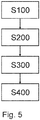
- Figure 5 shows a flow diagram of an exemplary coating process. According to a method step with the reference number “S100”, an edge 2a of the panel 2 is introduced into a coating medium flow via a recess 3c of the coating device 1.
- the coating medium B is conveyed to the inlet 3a of the coating device 1 by means of a shear-force-free pump 60 upstream of an inlet of the coating device 1 in the medium flow direction M to the inlet 3a of the coating device 1 sucked, and is pumped through the heater 70 designed as a flow heater to the coating device 1.
- the coating medium B is pumped almost without pressure up to the inlet 3a of the coating device 1.
- the coating medium B within the coating device 1 is conveyed by means of a vacuum device 40 downstream of a sequence of the coating device 1 in the medium flow direction M Coating device 1 sucked towards the separation system 50.
- the coating medium B is separated from a gas subjected to negative pressure by the separation system 50.
- the medium can be gently filtered through the sieve system 51 designed as a sieve basket and the medium can be conveyed in the circuit of the coating system 100.
- an air-medium mixture arises at the recess 3c of the coating device 1, which is designed with a counter-profile to the painting area of the panel 2. If a panel 2 is now driven past the coating device 1 - regardless of a running direction - the panel 2 is coated in its coating area by the air-medium mixture flowing against it, ie painted. The excess medium is sucked off and goes back into the circuit of the coating system 100.
- the quantity regulation of the coating medium is fully automated.
Landscapes
- Coating Apparatus (AREA)
- Finishing Walls (AREA)
Priority Applications (12)
| Application Number | Priority Date | Filing Date | Title |
|---|---|---|---|
| EP20165261.7A EP3885052B1 (fr) | 2020-03-24 | 2020-03-24 | Revêtement de bord d'un panneau au moyen d'un revêtement |
| ES20165261T ES2937071T3 (es) | 2020-03-24 | 2020-03-24 | Recubrimiento del borde de un panel con un medio de recubrimiento |
| PT201652617T PT3885052T (pt) | 2020-03-24 | 2020-03-24 | Revestimento do bordo de um painel com um meio de revestimento |
| PL20165261.7T PL3885052T3 (pl) | 2020-03-24 | 2020-03-24 | Powlekanie krawędzi panelu środkiem powlekającym |
| KR1020227036394A KR102791300B1 (ko) | 2020-03-24 | 2021-03-24 | 코팅 매체로의 패널의 에지 코팅 |
| EP21713669.6A EP4126392A1 (fr) | 2020-03-24 | 2021-03-24 | Revêtement de bord d'un panneau avec un milieu de revêtement |
| PCT/EP2021/057577 WO2021191280A1 (fr) | 2020-03-24 | 2021-03-24 | Revêtement de bord d'un panneau avec un milieu de revêtement |
| CN202180024285.0A CN115315319B (zh) | 2020-03-24 | 2021-03-24 | 利用涂层介质进行边缘涂布的面板 |
| MX2022011924A MX2022011924A (es) | 2020-03-24 | 2021-03-24 | Recubrimiento de bordes de un panel con un medio de recubrimiento. |
| BR112022018188-4A BR112022018188B1 (pt) | 2020-03-24 | 2021-03-24 | Sistema de revestimento para o revestimento da borda de um painel com um meio de revestimento |
| US17/913,243 US11779951B2 (en) | 2020-03-24 | 2021-03-24 | Edge-coating a panel with a coating medium |
| CA3176079A CA3176079A1 (fr) | 2020-03-24 | 2021-03-24 | Revetement de bord d'un panneau avec un milieu de revetement |
Applications Claiming Priority (1)
| Application Number | Priority Date | Filing Date | Title |
|---|---|---|---|
| EP20165261.7A EP3885052B1 (fr) | 2020-03-24 | 2020-03-24 | Revêtement de bord d'un panneau au moyen d'un revêtement |
Publications (2)
| Publication Number | Publication Date |
|---|---|
| EP3885052A1 true EP3885052A1 (fr) | 2021-09-29 |
| EP3885052B1 EP3885052B1 (fr) | 2022-11-30 |
Family
ID=69960427
Family Applications (2)
| Application Number | Title | Priority Date | Filing Date |
|---|---|---|---|
| EP20165261.7A Active EP3885052B1 (fr) | 2020-03-24 | 2020-03-24 | Revêtement de bord d'un panneau au moyen d'un revêtement |
| EP21713669.6A Pending EP4126392A1 (fr) | 2020-03-24 | 2021-03-24 | Revêtement de bord d'un panneau avec un milieu de revêtement |
Family Applications After (1)
| Application Number | Title | Priority Date | Filing Date |
|---|---|---|---|
| EP21713669.6A Pending EP4126392A1 (fr) | 2020-03-24 | 2021-03-24 | Revêtement de bord d'un panneau avec un milieu de revêtement |
Country Status (10)
| Country | Link |
|---|---|
| US (1) | US11779951B2 (fr) |
| EP (2) | EP3885052B1 (fr) |
| KR (1) | KR102791300B1 (fr) |
| CN (1) | CN115315319B (fr) |
| CA (1) | CA3176079A1 (fr) |
| ES (1) | ES2937071T3 (fr) |
| MX (1) | MX2022011924A (fr) |
| PL (1) | PL3885052T3 (fr) |
| PT (1) | PT3885052T (fr) |
| WO (1) | WO2021191280A1 (fr) |
Cited By (2)
| Publication number | Priority date | Publication date | Assignee | Title |
|---|---|---|---|---|
| IT202200005726A1 (it) * | 2022-03-23 | 2023-09-23 | Cefla Soc Cooperativa | Testa vacuum per la verniciatura di bordi di pannelli |
| DE102023200533A1 (de) | 2023-01-24 | 2024-07-25 | Josef Schiele | Beschichtungsanlage und Verfahren zur Beschichtung eines Teilbereichs eines Paneels |
Citations (1)
| Publication number | Priority date | Publication date | Assignee | Title |
|---|---|---|---|---|
| DE4021174A1 (de) * | 1990-07-03 | 1992-01-16 | Josef Schiele | Anlage zum durchlauf-vakuum-fluessigbeschichten |
Family Cites Families (32)
| Publication number | Priority date | Publication date | Assignee | Title |
|---|---|---|---|---|
| CH585920A5 (fr) * | 1974-06-07 | 1977-03-15 | Hoechst Ag | |
| SE419946B (sv) * | 1974-10-16 | 1981-09-07 | Inventing Ab | Sett och anordning for bestrykning av en lopande bana |
| US4231668A (en) | 1978-10-05 | 1980-11-04 | The Sherwin-Williams Company | Liquid power driven coating apparatus |
| DE4207090C2 (de) | 1992-03-06 | 1995-07-13 | Josef Schiele | Kantenbeschichtungskopf |
| AT401854B (de) | 1992-12-24 | 1996-12-27 | Blum Gmbh Julius | Schublade |
| US5614265A (en) * | 1994-05-16 | 1997-03-25 | Allied Tube & Conduit Corporation | In-line coating of steel tubing |
| US5453302A (en) * | 1994-05-16 | 1995-09-26 | Allied Tube & Conduit Corporation | In-line coating of steel tubing |
| DE19857045C2 (de) | 1998-12-10 | 2001-02-01 | Industrieservis Ges Fuer Innov | Beschichtung von Gegenständen |
| US6605153B2 (en) * | 1999-12-17 | 2003-08-12 | Tokyo Electron Limited | Coating film forming apparatus |
| DE10100518A1 (de) * | 2001-01-08 | 2002-07-11 | Josef Schiele Ohg | Kantenbeschichtungsvorrichtung |
| US6833157B2 (en) * | 2001-09-28 | 2004-12-21 | Fuji Photo Film Co., Ltd. | Coating method and apparatus |
| JP3991261B2 (ja) * | 2002-02-19 | 2007-10-17 | 富士フイルム株式会社 | 塗布方法 |
| JP3962860B2 (ja) * | 2002-02-19 | 2007-08-22 | 富士フイルム株式会社 | 塗布装置 |
| DE10216294B4 (de) | 2002-04-08 | 2008-04-03 | Gp Innovationsgesellschaft Mbh | Verfahren zum Beschichten von Festkörpern im Niedrigtemperaturbereich |
| JP2004223456A (ja) * | 2003-01-24 | 2004-08-12 | Fuji Photo Film Co Ltd | 塗布装置および塗布方法 |
| TWI362059B (en) * | 2004-11-25 | 2012-04-11 | Az Electronic Mat Ip Japan Kk | Photoresist coating solution supply system and method for supplying photoresist coating solution using thereof, and photoresist coating system using thereof |
| FI20080264L (fi) * | 2008-04-03 | 2009-10-04 | Beneq Oy | Pinnoitusmenetelmä ja -laite |
| DE102009034007A1 (de) | 2009-07-21 | 2011-01-27 | Dürr Systems GmbH | Beschichtungsanlage und Verfahren zum Beschichten eines Werkstücks |
| FI9160U1 (fi) * | 2010-01-04 | 2011-04-14 | Beneq Oy | Pinnoituslaite |
| US20120031327A1 (en) * | 2010-08-04 | 2012-02-09 | Love Iii Franklin S | Apparatus for controlled application of liquid streams to a substrate with diverted liquid collection system |
| EP2641665A1 (fr) | 2012-03-19 | 2013-09-25 | Deceuninck NV | Procédé en plusieurs étapes pour éléments de construction entièrement colorés |
| US20150072077A1 (en) | 2013-09-10 | 2015-03-12 | Armstrong World Industries, Inc. | System for applying a coating to a workpiece |
| US9266141B2 (en) | 2013-09-10 | 2016-02-23 | Awi Licensing Company | System for applying a coating to a workpiece |
| MX378928B (es) * | 2014-10-30 | 2025-03-11 | Centro De Investigacion En Mat Avanzados S C | Tobera de inyeccion de aerosoles y su metodo de utilizacion para depositar diferentes recubrimientos mediante deposito quimico de vapor asistido por aerosol. |
| WO2017098651A1 (fr) * | 2015-12-11 | 2017-06-15 | 東芝三菱電機産業システム株式会社 | Dispositif de formation de film d'application de brouillard et procédé de formation de film d'application de brouillard |
| CN108367307B (zh) * | 2016-01-22 | 2021-03-23 | 庄田德古透隆股份有限公司 | 端面涂布装置 |
| CN105772335A (zh) * | 2016-05-10 | 2016-07-20 | 深圳市华星光电技术有限公司 | 一种封框胶涂布装置以及方法 |
| US20190210060A1 (en) * | 2016-07-11 | 2019-07-11 | Toshiba Mitsubishi-Electric Industrial Systems Corporation | Mist coating forming apparatus and mist coating forming method |
| IT201600109468A1 (it) * | 2016-10-28 | 2018-04-28 | Sorbini Srl | Testa di verniciatura di tipo vacuum, adattabile al profilo del bordo di pannelli o altri manufatti da trattare |
| WO2018191207A1 (fr) * | 2017-04-10 | 2018-10-18 | Roche Diabetes Care, Inc. | Procédé de revêtement de filière à fente à réactifs multiples et dispositifs utiles |
| DK3590610T3 (en) | 2018-07-06 | 2022-06-07 | Saint Gobain Ecophon Ab | Fremgangsmåde til at coate et fliseelement. |
| KR20200098057A (ko) | 2019-02-11 | 2020-08-20 | 대우조선해양 주식회사 | 도료 히팅 기능을 구비한 도장 장치 |
-
2020
- 2020-03-24 EP EP20165261.7A patent/EP3885052B1/fr active Active
- 2020-03-24 PL PL20165261.7T patent/PL3885052T3/pl unknown
- 2020-03-24 PT PT201652617T patent/PT3885052T/pt unknown
- 2020-03-24 ES ES20165261T patent/ES2937071T3/es active Active
-
2021
- 2021-03-24 CN CN202180024285.0A patent/CN115315319B/zh active Active
- 2021-03-24 KR KR1020227036394A patent/KR102791300B1/ko active Active
- 2021-03-24 MX MX2022011924A patent/MX2022011924A/es unknown
- 2021-03-24 CA CA3176079A patent/CA3176079A1/fr active Pending
- 2021-03-24 WO PCT/EP2021/057577 patent/WO2021191280A1/fr not_active Ceased
- 2021-03-24 US US17/913,243 patent/US11779951B2/en active Active
- 2021-03-24 EP EP21713669.6A patent/EP4126392A1/fr active Pending
Patent Citations (1)
| Publication number | Priority date | Publication date | Assignee | Title |
|---|---|---|---|---|
| DE4021174A1 (de) * | 1990-07-03 | 1992-01-16 | Josef Schiele | Anlage zum durchlauf-vakuum-fluessigbeschichten |
Cited By (3)
| Publication number | Priority date | Publication date | Assignee | Title |
|---|---|---|---|---|
| IT202200005726A1 (it) * | 2022-03-23 | 2023-09-23 | Cefla Soc Cooperativa | Testa vacuum per la verniciatura di bordi di pannelli |
| EP4249132A1 (fr) * | 2022-03-23 | 2023-09-27 | Cefla Societa' Cooperativa | Tête de revêtement sous vide pour revêtir les bords de panneaux |
| DE102023200533A1 (de) | 2023-01-24 | 2024-07-25 | Josef Schiele | Beschichtungsanlage und Verfahren zur Beschichtung eines Teilbereichs eines Paneels |
Also Published As
| Publication number | Publication date |
|---|---|
| KR102791300B1 (ko) | 2025-04-03 |
| WO2021191280A1 (fr) | 2021-09-30 |
| PT3885052T (pt) | 2023-01-30 |
| US11779951B2 (en) | 2023-10-10 |
| MX2022011924A (es) | 2022-12-02 |
| CN115315319A (zh) | 2022-11-08 |
| ES2937071T3 (es) | 2023-03-23 |
| CN115315319B (zh) | 2024-12-03 |
| CA3176079A1 (fr) | 2021-09-30 |
| EP3885052B1 (fr) | 2022-11-30 |
| EP4126392A1 (fr) | 2023-02-08 |
| BR112022018188A2 (pt) | 2022-10-25 |
| KR20220149918A (ko) | 2022-11-09 |
| PL3885052T3 (pl) | 2023-03-27 |
| US20230166286A1 (en) | 2023-06-01 |
Similar Documents
| Publication | Publication Date | Title |
|---|---|---|
| EP1958899A1 (fr) | Dispositif d'alimentation de fluide | |
| DE102007041551A1 (de) | Pulversprühbeschichtungsvorrichtung und Beschichtungspulver-Fördervorrichtung dafür | |
| EP3885052B1 (fr) | Revêtement de bord d'un panneau au moyen d'un revêtement | |
| EP2696989A1 (fr) | Pompe à membrane et procédé de transport de poudre fine à l'aide d'une pompe à membrane | |
| EP2229532B1 (fr) | Compresseur à piston | |
| WO2016134397A1 (fr) | Dispositif de refoulement pneumatique et installation de dosage ainsi qu'installation de sablage comprenant une pompe à jet de produit coulant | |
| EP3141410B1 (fr) | Boitier de guidage d'air et appareil de ventilation, chauffage ou climatisation doté d'un tel boitier de guidage d'air | |
| DE102013205895A1 (de) | Pulverdichtstrompumpe zum Fördern von Beschichtungspulver sowie entsprechendes Verfahren | |
| EP2123864A1 (fr) | Nettoyage de compresseur | |
| DE69303447T2 (de) | Vakuumpumpgerät | |
| EP2781384B1 (fr) | Système de ventilateur pour filtration de cabine | |
| DE9411878U1 (de) | Vorrichtung und Anordnung zum Trocknen der Rohrleitungen des Gasleitungssystems eines Hauses | |
| DE10031848A1 (de) | Verfahren und Vorrichtung zum Herstellen von Filterstäben der tabakverarbeitenden Industrie | |
| DE102007048520A1 (de) | Sprühbeschichtungspulver-Fördervorrichtung und Pulversprühbeschichtungsvorrichtung | |
| EP3986811A1 (fr) | Dispositif de transport de pièces de préférence tabulaires, en particulier de manière horizontale | |
| DE315212C (fr) | ||
| EP1272412B1 (fr) | Procédé de transport répeté d'un fluide de rinçage | |
| DE202018105771U1 (de) | Ver- und/oder Entsorgungssystem zum Zuführen oder Abführen von Fluiden | |
| DE1532010C3 (de) | Fördervorrichtung für Zerkleinerungsgut mit einer Förderpumpe und einer Vacuumabsaugeanlage | |
| DE102015100350B3 (de) | Zahnradpumpe und Luftbefeuchtungsvorrichtung mit einer derartigen Zahnradpumpe | |
| DE3445054C2 (fr) | ||
| EP4609901A1 (fr) | Appareil de thérapie respiratoire | |
| DE102012109549B4 (de) | Verstellbarer Leitapparat für einen Abgasführungsabschnitt einer Turbine, und Abgasturbolader | |
| DE102023124833A1 (de) | Kanalinspektions- und/oder Wartungssystem mit Hochdruckmodul | |
| EP4257740A1 (fr) | Appareil d'entretien du linge comprenant une pompe |
Legal Events
| Date | Code | Title | Description |
|---|---|---|---|
| PUAI | Public reference made under article 153(3) epc to a published international application that has entered the european phase |
Free format text: ORIGINAL CODE: 0009012 |
|
| STAA | Information on the status of an ep patent application or granted ep patent |
Free format text: STATUS: THE APPLICATION HAS BEEN PUBLISHED |
|
| AK | Designated contracting states |
Kind code of ref document: A1 Designated state(s): AL AT BE BG CH CY CZ DE DK EE ES FI FR GB GR HR HU IE IS IT LI LT LU LV MC MK MT NL NO PL PT RO RS SE SI SK SM TR |
|
| STAA | Information on the status of an ep patent application or granted ep patent |
Free format text: STATUS: REQUEST FOR EXAMINATION WAS MADE |
|
| 17P | Request for examination filed |
Effective date: 20220329 |
|
| RBV | Designated contracting states (corrected) |
Designated state(s): AL AT BE BG CH CY CZ DE DK EE ES FI FR GB GR HR HU IE IS IT LI LT LU LV MC MK MT NL NO PL PT RO RS SE SI SK SM TR |
|
| GRAP | Despatch of communication of intention to grant a patent |
Free format text: ORIGINAL CODE: EPIDOSNIGR1 |
|
| STAA | Information on the status of an ep patent application or granted ep patent |
Free format text: STATUS: GRANT OF PATENT IS INTENDED |
|
| INTG | Intention to grant announced |
Effective date: 20220713 |
|
| GRAS | Grant fee paid |
Free format text: ORIGINAL CODE: EPIDOSNIGR3 |
|
| GRAA | (expected) grant |
Free format text: ORIGINAL CODE: 0009210 |
|
| STAA | Information on the status of an ep patent application or granted ep patent |
Free format text: STATUS: THE PATENT HAS BEEN GRANTED |
|
| AK | Designated contracting states |
Kind code of ref document: B1 Designated state(s): AL AT BE BG CH CY CZ DE DK EE ES FI FR GB GR HR HU IE IS IT LI LT LU LV MC MK MT NL NO PL PT RO RS SE SI SK SM TR |
|
| REG | Reference to a national code |
Ref country code: CH Ref legal event code: EP Ref country code: GB Ref legal event code: FG4D Free format text: NOT ENGLISH |
|
| REG | Reference to a national code |
Ref country code: AT Ref legal event code: REF Ref document number: 1534272 Country of ref document: AT Kind code of ref document: T Effective date: 20221215 Ref country code: DE Ref legal event code: R096 Ref document number: 502020002081 Country of ref document: DE |
|
| REG | Reference to a national code |
Ref country code: IE Ref legal event code: FG4D Free format text: LANGUAGE OF EP DOCUMENT: GERMAN |
|
| REG | Reference to a national code |
Ref country code: PT Ref legal event code: SC4A Ref document number: 3885052 Country of ref document: PT Date of ref document: 20230130 Kind code of ref document: T Free format text: AVAILABILITY OF NATIONAL TRANSLATION Effective date: 20230124 |
|
| REG | Reference to a national code |
Ref country code: NL Ref legal event code: FP |
|
| REG | Reference to a national code |
Ref country code: ES Ref legal event code: FG2A Ref document number: 2937071 Country of ref document: ES Kind code of ref document: T3 Effective date: 20230323 |
|
| REG | Reference to a national code |
Ref country code: LT Ref legal event code: MG9D |
|
| PG25 | Lapsed in a contracting state [announced via postgrant information from national office to epo] |
Ref country code: SE Free format text: LAPSE BECAUSE OF FAILURE TO SUBMIT A TRANSLATION OF THE DESCRIPTION OR TO PAY THE FEE WITHIN THE PRESCRIBED TIME-LIMIT Effective date: 20221130 Ref country code: NO Free format text: LAPSE BECAUSE OF FAILURE TO SUBMIT A TRANSLATION OF THE DESCRIPTION OR TO PAY THE FEE WITHIN THE PRESCRIBED TIME-LIMIT Effective date: 20230228 Ref country code: LT Free format text: LAPSE BECAUSE OF FAILURE TO SUBMIT A TRANSLATION OF THE DESCRIPTION OR TO PAY THE FEE WITHIN THE PRESCRIBED TIME-LIMIT Effective date: 20221130 Ref country code: FI Free format text: LAPSE BECAUSE OF FAILURE TO SUBMIT A TRANSLATION OF THE DESCRIPTION OR TO PAY THE FEE WITHIN THE PRESCRIBED TIME-LIMIT Effective date: 20221130 |
|
| PG25 | Lapsed in a contracting state [announced via postgrant information from national office to epo] |
Ref country code: RS Free format text: LAPSE BECAUSE OF FAILURE TO SUBMIT A TRANSLATION OF THE DESCRIPTION OR TO PAY THE FEE WITHIN THE PRESCRIBED TIME-LIMIT Effective date: 20221130 Ref country code: LV Free format text: LAPSE BECAUSE OF FAILURE TO SUBMIT A TRANSLATION OF THE DESCRIPTION OR TO PAY THE FEE WITHIN THE PRESCRIBED TIME-LIMIT Effective date: 20221130 Ref country code: IS Free format text: LAPSE BECAUSE OF FAILURE TO SUBMIT A TRANSLATION OF THE DESCRIPTION OR TO PAY THE FEE WITHIN THE PRESCRIBED TIME-LIMIT Effective date: 20230330 Ref country code: HR Free format text: LAPSE BECAUSE OF FAILURE TO SUBMIT A TRANSLATION OF THE DESCRIPTION OR TO PAY THE FEE WITHIN THE PRESCRIBED TIME-LIMIT Effective date: 20221130 Ref country code: GR Free format text: LAPSE BECAUSE OF FAILURE TO SUBMIT A TRANSLATION OF THE DESCRIPTION OR TO PAY THE FEE WITHIN THE PRESCRIBED TIME-LIMIT Effective date: 20230301 |
|
| P01 | Opt-out of the competence of the unified patent court (upc) registered |
Effective date: 20230526 |
|
| PG25 | Lapsed in a contracting state [announced via postgrant information from national office to epo] |
Ref country code: SM Free format text: LAPSE BECAUSE OF FAILURE TO SUBMIT A TRANSLATION OF THE DESCRIPTION OR TO PAY THE FEE WITHIN THE PRESCRIBED TIME-LIMIT Effective date: 20221130 Ref country code: RO Free format text: LAPSE BECAUSE OF FAILURE TO SUBMIT A TRANSLATION OF THE DESCRIPTION OR TO PAY THE FEE WITHIN THE PRESCRIBED TIME-LIMIT Effective date: 20221130 Ref country code: EE Free format text: LAPSE BECAUSE OF FAILURE TO SUBMIT A TRANSLATION OF THE DESCRIPTION OR TO PAY THE FEE WITHIN THE PRESCRIBED TIME-LIMIT Effective date: 20221130 Ref country code: DK Free format text: LAPSE BECAUSE OF FAILURE TO SUBMIT A TRANSLATION OF THE DESCRIPTION OR TO PAY THE FEE WITHIN THE PRESCRIBED TIME-LIMIT Effective date: 20221130 |
|
| REG | Reference to a national code |
Ref country code: DE Ref legal event code: R026 Ref document number: 502020002081 Country of ref document: DE |
|
| PG25 | Lapsed in a contracting state [announced via postgrant information from national office to epo] |
Ref country code: SK Free format text: LAPSE BECAUSE OF FAILURE TO SUBMIT A TRANSLATION OF THE DESCRIPTION OR TO PAY THE FEE WITHIN THE PRESCRIBED TIME-LIMIT Effective date: 20221130 Ref country code: AL Free format text: LAPSE BECAUSE OF FAILURE TO SUBMIT A TRANSLATION OF THE DESCRIPTION OR TO PAY THE FEE WITHIN THE PRESCRIBED TIME-LIMIT Effective date: 20221130 |
|
| PLBI | Opposition filed |
Free format text: ORIGINAL CODE: 0009260 |
|
| PLAX | Notice of opposition and request to file observation + time limit sent |
Free format text: ORIGINAL CODE: EPIDOSNOBS2 |
|
| PLAB | Opposition data, opponent's data or that of the opponent's representative modified |
Free format text: ORIGINAL CODE: 0009299OPPO |
|
| 26 | Opposition filed |
Opponent name: SCHIELE MASCHINENBAU GMBH Effective date: 20230829 |
|
| PG25 | Lapsed in a contracting state [announced via postgrant information from national office to epo] |
Ref country code: MC Free format text: LAPSE BECAUSE OF FAILURE TO SUBMIT A TRANSLATION OF THE DESCRIPTION OR TO PAY THE FEE WITHIN THE PRESCRIBED TIME-LIMIT Effective date: 20221130 |
|
| R26 | Opposition filed (corrected) |
Opponent name: SCHIELE MASCHINENBAU GMBH Effective date: 20230829 |
|
| PG25 | Lapsed in a contracting state [announced via postgrant information from national office to epo] |
Ref country code: SI Free format text: LAPSE BECAUSE OF FAILURE TO SUBMIT A TRANSLATION OF THE DESCRIPTION OR TO PAY THE FEE WITHIN THE PRESCRIBED TIME-LIMIT Effective date: 20221130 |
|
| PG25 | Lapsed in a contracting state [announced via postgrant information from national office to epo] |
Ref country code: LU Free format text: LAPSE BECAUSE OF NON-PAYMENT OF DUE FEES Effective date: 20230324 |
|
| PLAF | Information modified related to communication of a notice of opposition and request to file observations + time limit |
Free format text: ORIGINAL CODE: EPIDOSCOBS2 |
|
| REG | Reference to a national code |
Ref country code: IE Ref legal event code: MM4A |
|
| PG25 | Lapsed in a contracting state [announced via postgrant information from national office to epo] |
Ref country code: IE Free format text: LAPSE BECAUSE OF NON-PAYMENT OF DUE FEES Effective date: 20230324 |
|
| PLBB | Reply of patent proprietor to notice(s) of opposition received |
Free format text: ORIGINAL CODE: EPIDOSNOBS3 |
|
| PGFP | Annual fee paid to national office [announced via postgrant information from national office to epo] |
Ref country code: PT Payment date: 20250313 Year of fee payment: 6 |
|
| PGFP | Annual fee paid to national office [announced via postgrant information from national office to epo] |
Ref country code: BG Payment date: 20250321 Year of fee payment: 6 |
|
| PGFP | Annual fee paid to national office [announced via postgrant information from national office to epo] |
Ref country code: PL Payment date: 20250228 Year of fee payment: 6 Ref country code: CZ Payment date: 20250318 Year of fee payment: 6 |
|
| PGFP | Annual fee paid to national office [announced via postgrant information from national office to epo] |
Ref country code: ES Payment date: 20250429 Year of fee payment: 6 |
|
| PGFP | Annual fee paid to national office [announced via postgrant information from national office to epo] |
Ref country code: CH Payment date: 20250401 Year of fee payment: 6 |
|
| PG25 | Lapsed in a contracting state [announced via postgrant information from national office to epo] |
Ref country code: CY Free format text: LAPSE BECAUSE OF FAILURE TO SUBMIT A TRANSLATION OF THE DESCRIPTION OR TO PAY THE FEE WITHIN THE PRESCRIBED TIME-LIMIT; INVALID AB INITIO Effective date: 20200324 |
|
| PLBP | Opposition withdrawn |
Free format text: ORIGINAL CODE: 0009264 |
|
| PLAM | Termination of opposition procedure: information related to despatch of decision modified |
Free format text: ORIGINAL CODE: EPIDOSCOPC1 |
|
| PLBD | Termination of opposition procedure: decision despatched |
Free format text: ORIGINAL CODE: EPIDOSNOPC1 |
|
| REG | Reference to a national code |
Ref country code: DE Ref legal event code: R100 Ref document number: 502020002081 Country of ref document: DE |
|
| PG25 | Lapsed in a contracting state [announced via postgrant information from national office to epo] |
Ref country code: HU Free format text: LAPSE BECAUSE OF FAILURE TO SUBMIT A TRANSLATION OF THE DESCRIPTION OR TO PAY THE FEE WITHIN THE PRESCRIBED TIME-LIMIT; INVALID AB INITIO Effective date: 20200324 |
|
| PLBM | Termination of opposition procedure: date of legal effect published |
Free format text: ORIGINAL CODE: 0009276 |
|
| REG | Reference to a national code |
Ref country code: CH Ref legal event code: L10 Free format text: ST27 STATUS EVENT CODE: U-0-0-L10-L00 (AS PROVIDED BY THE NATIONAL OFFICE) Effective date: 20251119 |
|
| 27C | Opposition proceedings terminated |
Effective date: 20250813 |
|
| REG | Reference to a national code |
Ref country code: CH Ref legal event code: U11 Free format text: ST27 STATUS EVENT CODE: U-0-0-U10-U11 (AS PROVIDED BY THE NATIONAL OFFICE) Effective date: 20260401 |
|
| PGFP | Annual fee paid to national office [announced via postgrant information from national office to epo] |
Ref country code: GB Payment date: 20260324 Year of fee payment: 7 |
|
| PGFP | Annual fee paid to national office [announced via postgrant information from national office to epo] |
Ref country code: DE Payment date: 20260325 Year of fee payment: 7 |
|
| PGFP | Annual fee paid to national office [announced via postgrant information from national office to epo] |
Ref country code: AT Payment date: 20260320 Year of fee payment: 7 |
|
| PGFP | Annual fee paid to national office [announced via postgrant information from national office to epo] |
Ref country code: BE Payment date: 20260319 Year of fee payment: 7 Ref country code: IT Payment date: 20260324 Year of fee payment: 7 |
|
| PGFP | Annual fee paid to national office [announced via postgrant information from national office to epo] |
Ref country code: NL Payment date: 20260319 Year of fee payment: 7 |
|
| PGFP | Annual fee paid to national office [announced via postgrant information from national office to epo] |
Ref country code: FR Payment date: 20260323 Year of fee payment: 7 |
|
| PGFP | Annual fee paid to national office [announced via postgrant information from national office to epo] |
Ref country code: TR Payment date: 20260323 Year of fee payment: 7 |