EP4257740A1 - Appareil d'entretien du linge comprenant une pompe - Google Patents
Appareil d'entretien du linge comprenant une pompe Download PDFInfo
- Publication number
- EP4257740A1 EP4257740A1 EP23160985.0A EP23160985A EP4257740A1 EP 4257740 A1 EP4257740 A1 EP 4257740A1 EP 23160985 A EP23160985 A EP 23160985A EP 4257740 A1 EP4257740 A1 EP 4257740A1
- Authority
- EP
- European Patent Office
- Prior art keywords
- opening
- pump
- housing section
- laundry care
- washing liquid
- Prior art date
- Legal status (The legal status is an assumption and is not a legal conclusion. Google has not performed a legal analysis and makes no representation as to the accuracy of the status listed.)
- Withdrawn
Links
Images


Classifications
-
- D—TEXTILES; PAPER
- D06—TREATMENT OF TEXTILES OR THE LIKE; LAUNDERING; FLEXIBLE MATERIALS NOT OTHERWISE PROVIDED FOR
- D06F—LAUNDERING, DRYING, IRONING, PRESSING OR FOLDING TEXTILE ARTICLES
- D06F39/00—Details of washing machines not specific to a single type of machines covered by groups D06F9/00 - D06F27/00
- D06F39/02—Devices for adding soap or other washing agents
- D06F39/022—Devices for adding soap or other washing agents in a liquid state
-
- D—TEXTILES; PAPER
- D06—TREATMENT OF TEXTILES OR THE LIKE; LAUNDERING; FLEXIBLE MATERIALS NOT OTHERWISE PROVIDED FOR
- D06F—LAUNDERING, DRYING, IRONING, PRESSING OR FOLDING TEXTILE ARTICLES
- D06F33/00—Control of operations performed in washing machines or washer-dryers
- D06F33/30—Control of washing machines characterised by the purpose or target of the control
- D06F33/43—Control of cleaning or disinfection of washing machine parts, e.g. of tubs
-
- D—TEXTILES; PAPER
- D06—TREATMENT OF TEXTILES OR THE LIKE; LAUNDERING; FLEXIBLE MATERIALS NOT OTHERWISE PROVIDED FOR
- D06F—LAUNDERING, DRYING, IRONING, PRESSING OR FOLDING TEXTILE ARTICLES
- D06F33/00—Control of operations performed in washing machines or washer-dryers
- D06F33/30—Control of washing machines characterised by the purpose or target of the control
- D06F33/32—Control of operational steps, e.g. optimisation or improvement of operational steps depending on the condition of the laundry
- D06F33/37—Control of operational steps, e.g. optimisation or improvement of operational steps depending on the condition of the laundry of metering of detergents or additives
-
- D—TEXTILES; PAPER
- D06—TREATMENT OF TEXTILES OR THE LIKE; LAUNDERING; FLEXIBLE MATERIALS NOT OTHERWISE PROVIDED FOR
- D06F—LAUNDERING, DRYING, IRONING, PRESSING OR FOLDING TEXTILE ARTICLES
- D06F39/00—Details of washing machines not specific to a single type of machines covered by groups D06F9/00 - D06F27/00
- D06F39/08—Liquid supply or discharge arrangements
- D06F39/083—Liquid discharge or recirculation arrangements
- D06F39/085—Arrangements or adaptations of pumps
-
- D—TEXTILES; PAPER
- D06—TREATMENT OF TEXTILES OR THE LIKE; LAUNDERING; FLEXIBLE MATERIALS NOT OTHERWISE PROVIDED FOR
- D06F—LAUNDERING, DRYING, IRONING, PRESSING OR FOLDING TEXTILE ARTICLES
- D06F39/00—Details of washing machines not specific to a single type of machines covered by groups D06F9/00 - D06F27/00
- D06F39/10—Filtering arrangements
-
- D—TEXTILES; PAPER
- D06—TREATMENT OF TEXTILES OR THE LIKE; LAUNDERING; FLEXIBLE MATERIALS NOT OTHERWISE PROVIDED FOR
- D06F—LAUNDERING, DRYING, IRONING, PRESSING OR FOLDING TEXTILE ARTICLES
- D06F2103/00—Parameters monitored or detected for the control of domestic laundry washing machines, washer-dryers or laundry dryers
- D06F2103/42—Parameters monitored or detected for the control of domestic laundry washing machines, washer-dryers or laundry dryers related to filters or pumps
-
- D—TEXTILES; PAPER
- D06—TREATMENT OF TEXTILES OR THE LIKE; LAUNDERING; FLEXIBLE MATERIALS NOT OTHERWISE PROVIDED FOR
- D06F—LAUNDERING, DRYING, IRONING, PRESSING OR FOLDING TEXTILE ARTICLES
- D06F2103/00—Parameters monitored or detected for the control of domestic laundry washing machines, washer-dryers or laundry dryers
- D06F2103/68—Operation mode; Program phase
-
- D—TEXTILES; PAPER
- D06—TREATMENT OF TEXTILES OR THE LIKE; LAUNDERING; FLEXIBLE MATERIALS NOT OTHERWISE PROVIDED FOR
- D06F—LAUNDERING, DRYING, IRONING, PRESSING OR FOLDING TEXTILE ARTICLES
- D06F2105/00—Systems or parameters controlled or affected by the control systems of washing machines, washer-dryers or laundry dryers
- D06F2105/08—Draining of washing liquids
-
- D—TEXTILES; PAPER
- D06—TREATMENT OF TEXTILES OR THE LIKE; LAUNDERING; FLEXIBLE MATERIALS NOT OTHERWISE PROVIDED FOR
- D06F—LAUNDERING, DRYING, IRONING, PRESSING OR FOLDING TEXTILE ARTICLES
- D06F2105/00—Systems or parameters controlled or affected by the control systems of washing machines, washer-dryers or laundry dryers
- D06F2105/42—Detergent or additive supply
Definitions
- the present invention relates to a laundry care device with a pump.
- Certain device variants of conventional laundry care devices have fluid-carrying lines through which washing liquid is pumped using pumps to care for the laundry.
- contaminants such as lint, dirt or dust
- filter elements in particular lint filters, which are arranged in a pump and through which the washing liquid flows in order to filter the washing liquid.
- filter elements can become clogged due to an increasing accumulation of impurities during operation of the laundry care appliance, such filter elements must be cleaned regularly.
- advantageous access to the filter element arranged in the pump must be made possible by opening a maintenance opening, which is arranged in particular on a front side of the laundry care device near the bottom of the device, although this often and disadvantageously stands in the pump Washing liquid can escape through the maintenance opening into the installation room of the laundry care device.
- the publication EP 1 505 192 A2 discloses a laundry treatment machine with a pumping system.
- the publication EP 0 252 323 A2 reveals a combination of laundry machine and tumble dryer.
- the object according to the invention is achieved by a laundry care device, with a pump for pumping washing liquid, which is arranged in a pump receptacle of the laundry care device, the pump having a first housing section which delimits a suction chamber for sucking in washing liquid, in which A filter element for filtering the sucked-in washing liquid is arranged in the suction chamber, a maintenance opening for servicing the filter element being formed in the first housing section, the maintenance opening fluidly connecting an external area of the laundry care appliance with the suction chamber, the maintenance opening being closable by an unlockable cover element, the Pump has a second housing section which delimits a pump chamber with an impeller for pumping washing liquid, the pump having a connecting channel which fluidly connects a first opening of the first housing section to a second opening of the second housing section, the first opening being at least partially in one
- the first floor region of the first housing section is shaped, the first floor region facing a floor of the laundry care appliance in order to significantly reduce the leakage of washing
- the pump can completely or almost completely empty the suction chamber delimited by the first housing section during a pumping process. This means that after the pumping process, no or only a very small amount of washing liquid remains in the suction chamber, so that when the maintenance opening of the first housing section is subsequently opened as part of a maintenance process of the filter element, no washing liquid or only a very small amount of washing liquid can escape from the suction chamber through the open maintenance opening into the outside area of the laundry care device.
- the pump according to the present application sucks the washing liquid from the suction chamber through the first opening of the first housing section into the connecting channel, conveys the washing liquid through the connecting channel and through the second opening of the second housing section into the pump chamber, and then pumps the sucked washing liquid out of the pump chamber further.
- the pump can pump out washing liquid from the suction chamber during the pumping process as long as the washing liquid received in the suction chamber is present at the first opening of the first housing section. Since the pump according to the present application cannot deliver air, the pumping process ends as soon as the first opening of the first housing section is exposed, i.e. when there is no longer any washing liquid at the first opening.
- the first opening is only exposed when the washing liquid has been completely or almost completely pumped out of the suction chamber.
- the pump of the present application overcomes this disadvantage of conventional pumps by arranging the first opening in the bottom region of the first housing section so that there is no height difference between the first opening and is present in the floor area, so that after pumping out no washing liquid or only a very small amount of washing liquid remains in the suction chamber.
- an integrated pump concept can be implemented, which combines a variety of functions in the pump, so that a compact and space-saving arrangement of the pump in the laundry care device is possible, or compatibility with existing pump concepts is achieved.
- a laundry care device is a device that is used to care for laundry, such as a washing machine or a tumble dryer.
- a laundry care device is understood to mean a household laundry care device.
- a laundry care device that is used as part of household management and with which laundry is treated in normal household quantities.
- the maintenance opening is formed in a further first side region of the first housing section, which adjoins the first bottom region of the first housing section, the first side region facing a front side of the laundry care appliance.
- the further first side region of the first housing section faces the front of the laundry care appliance and the further first side region of the first housing section faces away from the pump chamber of the pump.
- the first housing section has a first side region which adjoins the first bottom region of the first housing section, the first side region and the further first side region being arranged at opposite ends of the first floor region.
- the first side area in particular faces the pump chamber and faces away from the front of the laundry care device.
- the further first side area in particular faces the front of the device and faces away from the pump chamber of the laundry care device.
- a lower edge of the maintenance opening formed in the further first side region is arranged above the first floor region in order to provide a buffer storage within the suction chamber between the first floor region and the lower edge of the maintenance opening for receiving washing liquid flowing back from the pump chamber into the suction chamber when deactivating the Provide pump.
- the lower edge of the maintenance opening corresponds to the area of the edge of the maintenance opening, which has the smallest distance to the installation floor.
- the buffer storage ensures that washing liquid flowing back from the pump chamber into the suction chamber cannot rise above the lower edge of the maintenance opening or can only rise to a very small extent, so that an escape of washing liquid from the maintenance opening is prevented, or significantly can be reduced.
- washing liquid can flow back when the pump is deactivated from the riser pipe into the pump chamber and from the pump chamber into the suction chamber of the pump, whereby the previously pumped empty suction chamber can at least partially fill again with washing liquid.
- the second opening is shaped as a concentric second opening, and/or the first opening is shaped as an elongated hole.
- the concentric second opening in particular has a circular cross section.
- the concentric, in particular circular, second opening in particular if the second opening is formed in a second side region of the second housing section which faces the suction chamber, achieves a coaxial arrangement of the second opening with an impeller rotation axis of the impeller, so that a particularly effective suction effect is ensured by the concentric, in particular circular, second opening.
- the first opening designed as an elongated hole has in particular a cross-sectional transverse axis which is longer than a cross-sectional vertical axis of the first opening designed as an elongated hole, so that the transition from the connecting channel into the suction chamber can be made as flat and wide as possible in order to maintain the limited installation space of the first To use the bottom area of the first housing section particularly effectively.
- the first opening and the second opening have an identical cross section, or the second opening has a cross section which is larger than the cross section of the first opening, or the first opening has a cross section which is larger than the cross section the second opening.
- the second opening is formed at least in sections in a second floor region of the second housing section facing the floor of the laundry care appliance, in particular the connecting channel running at least in sections below the first floor region of the first housing section and below the second floor region of the second housing section.
- the connecting channel By arranging the connecting channel at least in sections below the first and second base region, the connecting channel itself also provides a further buffer storage, which can accommodate washing liquid flowing back from the pump chamber after the pump has been deactivated, before the washing liquid flowing back penetrates into the suction chamber.
- the connecting channel is designed in particular as a flat and wide connecting channel, with in particular a cross-sectional transverse axis of the connecting channel being longer than a cross-sectional vertical axis of the connecting channel, so that the installation space between the first and second floor regions and the underside of the laundry care appliance can be used advantageously.
- the impeller arranged in the pump chamber faces the second base region, with an impeller rotation axis of the impeller intersecting the cross section of the second opening.
- the second opening is formed at least in sections in a second side region of the second housing section facing the suction chamber, in particular the connecting channel being at least extends in sections from below the first bottom region of the first housing section to the second side region.
- the second side region adjoins a second bottom region of the second housing section.
- the second housing section has a further second side region which adjoins the second bottom region of the second housing section, the second side region and the further second side region being arranged at opposite ends of the second floor region.
- the second side area in particular faces the suction chamber and faces the front of the laundry care appliance.
- the further second side area in particular faces away from the suction chamber and faces away from the front of the laundry care appliance.
- the connecting channel runs in particular at least in sections between the first housing section and the second housing section, the connecting channel in this case is designed in particular as a connecting channel that is curved at least in sections.
- the connecting channel has a first curvature, which is arranged on a first region of the connecting channel facing the first opening, and the connecting channel has a second curvature, which is arranged on a second region of the connecting channel facing the second opening, wherein the first and second curvatures in particular have opposite directions of curvature.
- the first and/or second curvature can include a rounded inner surface of the connecting channel, or alternatively can also include kinks.
- the first curvature is obtained in particular by sections of the connecting channel that extend at an angle to one another, the angle defining the first curvature between the sections extending at an angle to one another in particular comprising a range between 160 ° and 200 °, in particular 180 °, so that through the first Opening in the first floor area pumped washing liquid is deflected through the first curvature in such a way that the washing liquid flows upwards in relation to the floor of the laundry care appliance.
- the second curvature is obtained in particular by further sections of the connecting channel extending at an angle to one another, the angle defining the second curvature between the further sections extending at an angle to one another in particular comprising a range between 70° and 110°, in particular 90°, so that through In particular, washing liquid pumped upwards through the connecting channel can be deflected through the second curvature towards the second side region of the second housing section.
- the first housing section extends along a first longitudinal axis
- the second housing section extends along a second longitudinal axis, the first and second longitudinal axes being arranged at an angle to one another.
- the first longitudinal axis runs centrally between the first bottom region of the first housing section and a first ceiling region of the first housing section facing away from the first floor region, the first longitudinal axis in particular intersects a first side region and a further first side region of the first housing section.
- the second longitudinal axis runs centrally between the second bottom region of the second housing section and a second ceiling region of the second housing section facing away from the second floor region, the second longitudinal axis in particular intersecting a second side region and a further second side region of the first housing section.
- the angle between the first and second longitudinal axes is between 30° and 60°, in particular 45°.
- the connecting channel is arranged coaxially to an impeller rotation axis of the impeller, with the impeller rotation axis of the impeller extending parallel to the second longitudinal axis, so that the connecting channel is also arranged at an angle to the first longitudinal axis, which improves the inflow behavior of the washing liquid from the connecting channel into the pump chamber , and whereby the second opening can be relocated to a higher area of the second housing section, so that a rise of air bubbles present in the washing liquid contributes to advantageous ventilation.
- a cross-sectional height of the connecting channel decreases from the second opening towards the first opening and a cross-sectional width of the connecting channel increases from the second opening towards the first opening, in particular while maintaining the entire cross-sectional area of the connecting channel, or in particular by expanding the entire Cross-sectional area of the connecting channel from the second opening towards the first opening.
- the second housing section has a circular inner contour, with the connecting channel extending from the second opening of the second housing section connecting tangentially to the second housing section.
- the Venturi effect which occurs through the water ring, enables washing liquid to be sucked in through the second opening into the pump chamber, even if the second opening is not arranged coaxially to the impeller rotation axis.
- the Venturi effect is based on the fact that the flow speed of the water ring in the pump chamber is used to generate a negative pressure whose magnitude is greater than the excess pressure caused by the centrifugal force in the water ring at this point.
- the second opening is not formed centrally in a side region of the second housing section, but rather the second opening is formed in particular on a second bottom region of the second housing section.
- the impeller rotation axis of the impeller extends at an angle, in particular orthogonally, to a channel longitudinal axis of the connecting channel.
- the laundry care device has a riser pipe which connects the pump chamber to a pump-out opening of a device housing of the laundry care device.
- the pump-out opening is at a higher level than the height level of the pump.
- the laundry care device has a check valve which is designed to prevent washing liquid from flowing back from the riser into the pump chamber when the pump is deactivated.
- check valve prevents washing liquid present in the riser pipe from flowing back into the pump chamber and from there through the connecting channel into the suction chamber of the pump after the pump has been deactivated.
- the check valve is arranged on the second housing section of the pump.
- the check valve is designed as a ball check valve, which comprises a ball which is received in a sealing seat of the check valve.
- the ball is provided with a soft-elastic coating or formed from a soft-elastic material in order to form a sealing seal with the sealing seat.
- first housing section and the second housing section of the pump are formed in one piece, in particular the first housing section, the second housing section and the check valve being formed in one piece.
- the object according to the invention is achieved by a method for pumping washing liquid in a laundry care appliance, wherein the laundry care appliance has a pump for pumping washing liquid, which is arranged in a pump receptacle of the laundry care appliance, wherein the pump has a first housing section which has a Suction chamber for sucking in washing liquid, a filter element for filtering the sucked-in washing liquid being arranged in the suction chamber, a maintenance opening for servicing the filter element being formed in the first housing section, the maintenance opening fluidly connecting an outer area of the laundry care appliance with the suction chamber, the Maintenance opening can be closed by an unlockable cover element, the pump having a second housing section which delimits a pump chamber with an impeller for pumping washing liquid, the pump having a connecting channel which fluidly connects a first opening of the first housing section to a second opening of the second housing section, the first opening being at least partially in a first bottom region of the first Housing section is shaped, wherein the first floor area faces a floor of
- the detection device in particular has an output element for issuing a message to the user of the laundry care device that a maintenance interval of the filter element is pending, so that the user can open the maintenance opening after receiving the message.
- Fig. 1 shows a schematic view of a laundry care device 100, such as a washing machine.
- the laundry care appliance 100 includes a dispenser bowl 101 into which laundry care substance, such as detergent, can be filled.
- the laundry care device 100 includes a door 103 for loading the laundry care device 100 with laundry.
- the laundry care device 100 has various operating elements 105 for operating the laundry care device 100.
- the laundry care device 100 has a device housing 107 and stands on a floor 109.
- the laundry care device 100 has a cover element 111, which reversibly closes a maintenance opening 113 formed in a pump housing of a pump, so that a user of the laundry care device 100 has access to an in Fig. 1 Filter element, not shown, of the pump of the laundry care device 100 can be obtained in order to maintain the filter element, in particular to clean it.
- Fig. 2 shows a perspective view of a pump of a laundry care device according to a comparative example.
- Fig. 2 is a sectional view of the pump 115 shown, which in an in Fig. 2 pump receptacle of the laundry care device 100, not shown.
- the pump 115 has a first housing section 117 which delimits a suction chamber 119 for sucking in washing liquid, and has a second housing section 121 which delimits a pump chamber 123 for pumping washing liquid.
- the first housing section 117 has a first opening 125, which is connected to a second opening 129 of the second housing section 121 by a connecting channel 127.
- the first housing section 117 also has a suction port 133 for sucking washing liquid into the suction chamber 119.
- the second housing section 121 also has a pump nozzle 135, which has an in Fig. 2 Riser pipe, not shown, is connected for pumping out washing liquid from the pump chamber 123.
- An impeller 137 is arranged in the pump chamber 123, which is set in rotation by a pump drive 139 and generates a pump pressure in order to suck in washing liquid through the suction port 133 into the suction chamber 119, and from the suction chamber 119 through the connecting channel 127 into the pump chamber 123 , and to pump the sucked washing liquid from the pump chamber 123 with pressure through the pump nozzle 135 into the riser.
- the cover element 111, the two housing sections 117, 121 and the impeller 137 are arranged coaxially, with the pump 115 being arranged very far down in the laundry care appliance 100, in particular just above the base plate, in order to gain sufficient drainage height from the tub and in order to to enable gravity-induced self-starting of a ventilated radial centrifugal pump again.
- This riser pipe is used to prevent unwanted leakage of washing liquid to prevent the laundry care device 100, since the pump 115, in the design of a mostly radial centrifugal pump as a fluid machine, cannot work as a valve.
- the suction chamber 119 there is also an in Fig. 2 Filter element, not shown, in particular foreign body trap, arranged, which is designed to filter out impurities from the washing liquid flowing through the suction chamber 119.
- the first housing section 117 has a maintenance opening 113, which is reversibly closed by a cover element 111.
- the suction chamber 119 and the pump chamber 123 are almost completely filled with washing liquid. If no more washing liquid flows through the suction port 133, the suction chamber 119 is pumped empty to the lower edge of the first opening 125, as indicated by the first level 143 in the Fig. 2 is shown. Since the pump 115, which is designed in particular as a centrifugal pump, can pump almost no air, the riser from the pump nozzle 123 remains filled with washing liquid up to the highest point of the water mountain in the riser as long as the pump 115 is still activated.
- the washing liquid flows through the maintenance opening 113 out of the suction chamber 119 until the washing liquid in the suction chamber 119 reaches the lower edge of the maintenance opening 113, as indicated by the third level 147 in the Fig. 2 is shown, which is disadvantageous because it is difficult to collect the leaking washing liquid with a container because of the small distance to the floor.
- the corresponding washing liquid emerging from the maintenance opening 113 is often not absorbable by the user of the laundry care appliance 100, especially with a volume of 300 ml or more, and can lead to contamination of the installation space of the laundry care appliance 100, which is disadvantageous.
- Fig. 3 shows a perspective view of a pump of a laundry care device according to a first exemplary embodiment.
- Fig. 3 shows a perspective view of a pump of a laundry care device according to a first exemplary embodiment.
- the elements of the pump 115 see the comments Fig. 2 referred.
- the first housing section 117 delimiting the suction chamber 119 has a first floor region 151, which faces the installation floor 109 of the laundry care appliance 100.
- the first housing section 117 has a first side region 153, which faces the second housing section 121, or the pump chamber 123, and a further first side region 154, which faces away from the pump chamber 123 or faces a front of the laundry care appliance 100.
- the first housing section 117 has a first cover area 156, which faces away from the first bottom area 151. Both the first floor area 151 and the first cover area 156 connect the first side area 153 with the further first side area 154.
- the first opening 125 formed in the first housing section 117 is formed at least in sections in the first base region 151, in particular between the first base region 151 and the first side region 153.
- the first opening 125 is shaped in particular as an elongated hole.
- the washing liquid can be drained up to the in Fig. 2 shown first level 143 are pumped out, so that even if washing liquid subsequently flows back from the riser of the in Fig. 2 fifth level 150 shown is not exceeded, so that no washing liquid emerges from the maintenance opening 113.
- the height difference between a fifth level 150 on the underside of the maintenance opening 113 and the second level 145 on the first floor area 151 defines a buffer area for washing liquid.
- the second housing section 121 delimiting the pump chamber 123 has a second floor region 155, which faces the installation floor 109 of the laundry care appliance 100.
- the second housing section 121 has a second side region 157, which faces the first housing section 117 or the suction chamber 119, and a further second side region 158, which faces away from the pump chamber 123 and a front of the laundry care appliance 100.
- the second housing section 121 has a second cover area 160, which faces away from the second bottom area 155. Both the second floor area 155 and the second cover area 160 connect the second side area 157 with the further second side area 158.
- the second opening 129 formed in the second housing section 121 is formed at least in sections in the second side region 157, in particular in the middle of the second side region 157.
- the second opening 129 is in particular shaped as a concentric second opening 129, which is arranged concentrically to the impeller 137 in order to ensure effective pumping out of washing liquid.
- the connecting channel 127 connects the first opening 125 with the second opening 129, with the connecting channel 127 running at least in sections below the first floor region 151.
- the connecting channel 127 here has a first curvature 159, which is arranged in a first region of the connecting channel 127 facing the first opening 125, and here has a second curvature 161, which is arranged in a second region of the connecting channel 127 facing the second opening 129 is.
- the first and/or second curvature 159, 161 can form a rounded course of the connecting channel 127, or can the first and/or second curvature 159, 161 form an angular course of the connecting channel 127, as in Fig. 3 is shown.
- the first curvature 159 includes according to the Fig. 3 an angle of approx. 180°.
- the second curvature 161 includes according to the Fig. 3 an angle of approx. 90°.
- the connecting channel 127 is guided as deep as possible from the center of the second housing section 121 as an angled or curved tube to below the first housing section 117.
- the pump 115 can suck, ie the suction level is brought to a significantly lower point so that the suction chamber 119 can be pumped almost completely empty.
- Fig. 4 shows a perspective view of a pump of a laundry care device according to a second exemplary embodiment.
- Fig. 4 shows a perspective view of a pump of a laundry care device according to a second exemplary embodiment.
- the elements of the pump 115 see the comments Fig. 2 and Fig. 3 referred.
- the first opening 125 is formed in the first bottom region 151 of the first housing section 117, in particular between the first bottom region 151 and the first side region 153, and that the second opening 129 is formed in the second bottom region 155 of the second housing section 121.
- the first side region 153 of the first housing section 117 and the second side region 157 of the second housing section 121 are formed at least in sections by the same housing wall.
- the connecting channel 127 runs at least in sections below the first bottom region 151 of the first housing section 117 and at least in sections below the second bottom region 155 of the second housing section 121.
- the pump nozzle is arranged on a further second side area 158 opposite the second side area 157, and the pump drive 139 is arranged above the ceiling area 160 of the second housing section 121, so that the impeller rotation axis of the impeller 137 has the cross section of the second Opening 129 cuts.
- washing liquid can also be used up to the in Fig. 4 shown first level 143 are pumped out, so that even if washing liquid subsequently flows back from the riser, an in Fig. 4 fifth level 150 shown is not exceeded, so that no washing liquid emerges from the maintenance opening 113.
- Fig. 5 shows a perspective view of a pump of a laundry care device according to a third exemplary embodiment.
- Fig. 5 shows a perspective view of a pump of a laundry care device according to a third exemplary embodiment.
- the elements of the pump 115 see the comments Fig. 2 , Fig. 3 and Fig. 4 referred.
- the second housing section 121 is arranged obliquely to the first housing section 117.
- a first longitudinal axis 165 of the first housing section 117 extends parallel to the installation base 109, with a second longitudinal axis 167 of the second housing section 121 extending at an angle to the first longitudinal axis 165, the angle between the first and second longitudinal axes 165, 167 being in particular approximately 45° amounts.
- the fact that the second opening 129 is arranged in the second side region 157 of the second housing section 121 results in an optimal coaxial arrangement of the Connecting channel 127 to the impeller rotation axis of the impeller 137 and a sharp deflection of the washing liquid before entering the pump chamber 123 is prevented.
- the connecting channel 127 also extends at an angle to the longitudinal axis 165 of the first housing section 167 and the cross section of the connecting channel 127 from the second opening 129 to the first opening 125 can change from round to flat.
- the connecting channel 127 is arranged essentially coaxially to the impeller 137, wherein the shape of the cross section of the connecting channel 127 from the second opening 129 to the first opening 125 can be changed from a round cross section to an elongated hole-shaped cross section, in which case the cross sectional area of the first and second opening 125, 129 can be essentially identical, or the cross-sectional area of the first opening 125 can even be larger than the cross-sectional area of the second opening 129 in order to compensate for the advantages of the circular flow cross-section with regard to the pressure loss.
- the oblique arrangement of the second housing section 121 relative to the first housing section 117 results in two advantages.
- the connecting channel 127 does not open into the pump chamber 123 with a sharp bend, which improves the inflow behavior.
- the second opening 129 is positioned at the highest point of the pump chamber 123 and the obliquely oriented pump chamber 123 promotes the rise of air bubbles, which significantly improves the venting behavior.
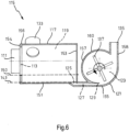
- Fig. 6 shows a perspective view of a pump of a laundry care device according to a fourth exemplary embodiment.
- the elements of the pump 115 see the comments Fig. 2 , Fig. 3 , Fig. 4 and Fig. 5 referred.
- the second housing section 121 has a circular inner contour, with the connecting channel 127 extending from the second opening 129 of the second housing section 121 adjoining the second housing section 121 tangentially.
- the Venturi effect is used to pump washing liquid into the pump chamber 123 at a height which lies below the impeller rotation axis of the impeller 137.
- the Venturi effect is achieved in particular by a flat and wide course of the connecting channel 127.
- the flow velocity of a water ring formed in the pump chamber 123 is used to generate a negative pressure, the amount of which is greater than the excess pressure generated by the centrifugal force at this point. A suction possibility is thus created in the pump chamber 123 with a horizontal impeller 137 at a low height.
- the Venturi effect can be created particularly advantageously by appropriately designing the connecting channel 127 in the area of the second opening 129, for example with a long tongue which delimits a flat inlet channel into the pump chamber 123.
- Figures 3 , 4 , 5 and 6 illustrated embodiments can also be provided with a check valve in order to reduce the amount of washing liquid flowing back from the riser into the suction chamber 119 when the pump 115 is switched off.
- Figures 3 , 4 , 5 and 6 illustrated embodiments can also be provided with a sufficient buffer volume, that is, the distance between the lower edge of the maintenance opening 113 and the first bottom region 151 of the first housing section 117 is sufficiently large to accommodate even a larger amount of washing liquid, which comes out of the riser pipe when the pump 115 is switched off the suction chamber 119 flows back, advantageously recorded.
- Fig. 7 shows a schematic representation of a method for pumping washing liquid in a laundry care device.
- the method 200 includes, as a first method step, activating 201 the detection device for detecting a maintenance interval of the filter element by the controller.
- the method 200 includes activating 203 the pump 115 depending on the maintenance interval detected by the detection device in order to pump out washing liquid from the suction chamber 119 before opening the maintenance opening 113.
Landscapes
- Engineering & Computer Science (AREA)
- Textile Engineering (AREA)
- Detail Structures Of Washing Machines And Dryers (AREA)
- Structures Of Non-Positive Displacement Pumps (AREA)
Applications Claiming Priority (1)
| Application Number | Priority Date | Filing Date | Title |
|---|---|---|---|
| DE102022203313.2A DE102022203313A1 (de) | 2022-04-04 | 2022-04-04 | Wäschepflegegerät mit einer Pumpe |
Publications (1)
| Publication Number | Publication Date |
|---|---|
| EP4257740A1 true EP4257740A1 (fr) | 2023-10-11 |
Family
ID=85569837
Family Applications (1)
| Application Number | Title | Priority Date | Filing Date |
|---|---|---|---|
| EP23160985.0A Withdrawn EP4257740A1 (fr) | 2022-04-04 | 2023-03-09 | Appareil d'entretien du linge comprenant une pompe |
Country Status (3)
| Country | Link |
|---|---|
| EP (1) | EP4257740A1 (fr) |
| CN (1) | CN116892108A (fr) |
| DE (1) | DE102022203313A1 (fr) |
Citations (12)
| Publication number | Priority date | Publication date | Assignee | Title |
|---|---|---|---|---|
| US3385085A (en) * | 1964-02-25 | 1968-05-28 | Hupp Corp | Laundry equipment |
| EP0252323A2 (fr) | 1986-07-11 | 1988-01-13 | INDUSTRIE ZANUSSI S.p.A. | Machine combinée à laver et à sécher le linge |
| DE69518825T2 (de) * | 1995-03-31 | 2001-04-12 | Daewoo Electronics Co., Ltd. | Laugefilter in einer Waschmaschine |
| EP1505192A2 (fr) | 2003-08-04 | 2005-02-09 | BSH Bosch und Siemens Hausgeräte GmbH | Machine de traitement du linge avec système de pompe de vidange |
| JP2006204717A (ja) * | 2005-01-31 | 2006-08-10 | Toshiba Corp | ドラム式洗濯機 |
| JP2006262969A (ja) * | 2005-03-22 | 2006-10-05 | Sharp Corp | ドラム式洗濯機 |
| CN102535116A (zh) * | 2010-10-07 | 2012-07-04 | 日立空调·家用电器株式会社 | 洗衣机及洗涤干燥机 |
| WO2015131618A1 (fr) * | 2014-03-05 | 2015-09-11 | 海尔集团技术研发中心 | Procédé de commande de nettoyage d'ensemble filtre d'un système de filtration d'eau de circulation de machine à laver |
| US20170306544A1 (en) * | 2014-09-22 | 2017-10-26 | Qingdao Haier Smart Technology R&D Co., Ltd. | Self-cleaning method for filter assembly of washing machine |
| WO2020039770A1 (fr) * | 2018-08-22 | 2020-02-27 | パナソニックIpマネジメント株式会社 | Lave-linge |
| DE102019121992A1 (de) * | 2019-08-15 | 2021-02-18 | Miele & Cie. Kg | Waschmaschine oder Waschtrockner mit einem Ablaufsystem |
| CN114059277A (zh) * | 2020-08-07 | 2022-02-18 | 天津海尔洗涤电器有限公司 | 一种洗衣机及洗衣机的控制方法 |
Family Cites Families (2)
| Publication number | Priority date | Publication date | Assignee | Title |
|---|---|---|---|---|
| KR20070102056A (ko) | 2006-04-13 | 2007-10-18 | 삼성전자주식회사 | 배수펌프를 구비하는 세탁기 |
| IT201800009963A1 (it) | 2018-10-31 | 2020-05-01 | UFI Innovation Center SRL | Lavatrice con gruppo filtro |
-
2022
- 2022-04-04 DE DE102022203313.2A patent/DE102022203313A1/de active Pending
-
2023
- 2023-03-09 EP EP23160985.0A patent/EP4257740A1/fr not_active Withdrawn
- 2023-04-03 CN CN202310343227.5A patent/CN116892108A/zh active Pending
Patent Citations (12)
| Publication number | Priority date | Publication date | Assignee | Title |
|---|---|---|---|---|
| US3385085A (en) * | 1964-02-25 | 1968-05-28 | Hupp Corp | Laundry equipment |
| EP0252323A2 (fr) | 1986-07-11 | 1988-01-13 | INDUSTRIE ZANUSSI S.p.A. | Machine combinée à laver et à sécher le linge |
| DE69518825T2 (de) * | 1995-03-31 | 2001-04-12 | Daewoo Electronics Co., Ltd. | Laugefilter in einer Waschmaschine |
| EP1505192A2 (fr) | 2003-08-04 | 2005-02-09 | BSH Bosch und Siemens Hausgeräte GmbH | Machine de traitement du linge avec système de pompe de vidange |
| JP2006204717A (ja) * | 2005-01-31 | 2006-08-10 | Toshiba Corp | ドラム式洗濯機 |
| JP2006262969A (ja) * | 2005-03-22 | 2006-10-05 | Sharp Corp | ドラム式洗濯機 |
| CN102535116A (zh) * | 2010-10-07 | 2012-07-04 | 日立空调·家用电器株式会社 | 洗衣机及洗涤干燥机 |
| WO2015131618A1 (fr) * | 2014-03-05 | 2015-09-11 | 海尔集团技术研发中心 | Procédé de commande de nettoyage d'ensemble filtre d'un système de filtration d'eau de circulation de machine à laver |
| US20170306544A1 (en) * | 2014-09-22 | 2017-10-26 | Qingdao Haier Smart Technology R&D Co., Ltd. | Self-cleaning method for filter assembly of washing machine |
| WO2020039770A1 (fr) * | 2018-08-22 | 2020-02-27 | パナソニックIpマネジメント株式会社 | Lave-linge |
| DE102019121992A1 (de) * | 2019-08-15 | 2021-02-18 | Miele & Cie. Kg | Waschmaschine oder Waschtrockner mit einem Ablaufsystem |
| CN114059277A (zh) * | 2020-08-07 | 2022-02-18 | 天津海尔洗涤电器有限公司 | 一种洗衣机及洗衣机的控制方法 |
Also Published As
| Publication number | Publication date |
|---|---|
| DE102022203313A1 (de) | 2023-10-05 |
| CN116892108A (zh) | 2023-10-17 |
Similar Documents
| Publication | Publication Date | Title |
|---|---|---|
| DE10046349B4 (de) | Haushaltgerät | |
| DE69220187T2 (de) | Automatischer Beckenreiniger | |
| EP4257740A1 (fr) | Appareil d'entretien du linge comprenant une pompe | |
| EP1913262B1 (fr) | Corps de pompe, pompe et appareil menager a circulation d'eau | |
| EP1973460B1 (fr) | Lave-vaisselle | |
| EP3839260B1 (fr) | Pompe centrifuge dotée d'une soupape automatique | |
| EP3411520B1 (fr) | Appareil d'entretien du linge muni d'une commande de pompe | |
| DE19909310B4 (de) | Wäschebehandlungsmaschine | |
| DE102008054998B3 (de) | Waschmaschine, für die Waschmaschine geeignetes Pumpensystem sowie Verfahren zu ihrem Betrieb | |
| DE69932439T2 (de) | Geschirrspülmaschine mit verbesserter trocknung | |
| DE29514402U1 (de) | Vorrichtung zum Verbessern des Ansaugverhaltens von Strömungsförderpumpen | |
| WO2012143286A1 (fr) | Lave-vaisselle | |
| DE102022129366B4 (de) | Reinigungschemiebaugruppe für ein Gargerät und Gargerät mit einer solchen Baugruppe | |
| WO2020078705A2 (fr) | Lave-vaisselle ménager pourvu d'un système de filtre autonettoyant | |
| DE10161300B4 (de) | Wäschebehandlungsmaschine in Form einer Waschmaschine oder eines Wäschetrockners | |
| EP1272412B1 (fr) | Procédé de transport répeté d'un fluide de rinçage | |
| DE102006057683B3 (de) | Gargerät mit Rückflußsicherung vor Dampfgenerator | |
| DE102018210207B4 (de) | Wasserführendes Haushaltsgerät mit einer Impellerpumpe | |
| WO1999035996A1 (fr) | Procede et dispositif pour brosser les dents et la gencive | |
| DE102020124140A1 (de) | Waschautomat und Verfahren zum Betreiben eines Waschautomaten | |
| EP1762170B1 (fr) | Lave-vaisselle | |
| BE1030879B1 (de) | Filtervorrichtung für eine Waschmaschine, Waschmaschine und Verfahren zum Betrieb einer Waschmaschine | |
| DE10318862B4 (de) | Wasserführendes Haushaltgerät mit einer Entleerungspumpe sowie Entleerungspumpe | |
| DE10017243A1 (de) | Verfahren zum Betreiben einer Geschirrspülmaschine | |
| DE60021728T2 (de) | Filtereinheit fuer eine Waschmaschine |
Legal Events
| Date | Code | Title | Description |
|---|---|---|---|
| PUAI | Public reference made under article 153(3) epc to a published international application that has entered the european phase |
Free format text: ORIGINAL CODE: 0009012 |
|
| STAA | Information on the status of an ep patent application or granted ep patent |
Free format text: STATUS: THE APPLICATION HAS BEEN PUBLISHED |
|
| AK | Designated contracting states |
Kind code of ref document: A1 Designated state(s): AL AT BE BG CH CY CZ DE DK EE ES FI FR GB GR HR HU IE IS IT LI LT LU LV MC ME MK MT NL NO PL PT RO RS SE SI SK SM TR |
|
| STAA | Information on the status of an ep patent application or granted ep patent |
Free format text: STATUS: THE APPLICATION IS DEEMED TO BE WITHDRAWN |
|
| 18D | Application deemed to be withdrawn |
Effective date: 20240412 |