EP3885181A1 - Leistungsinformationverarbeitungsvorrichtung, leistungsinformationverarbeitungssystem und leistungsinformationverarbeitungsverfahren - Google Patents
Leistungsinformationverarbeitungsvorrichtung, leistungsinformationverarbeitungssystem und leistungsinformationverarbeitungsverfahren Download PDFInfo
- Publication number
- EP3885181A1 EP3885181A1 EP21162915.9A EP21162915A EP3885181A1 EP 3885181 A1 EP3885181 A1 EP 3885181A1 EP 21162915 A EP21162915 A EP 21162915A EP 3885181 A1 EP3885181 A1 EP 3885181A1
- Authority
- EP
- European Patent Office
- Prior art keywords
- power
- information
- electric
- power system
- system network
- Prior art date
- Legal status (The legal status is an assumption and is not a legal conclusion. Google has not performed a legal analysis and makes no representation as to the accuracy of the status listed.)
- Granted
Links
Images


Classifications
-
- B—PERFORMING OPERATIONS; TRANSPORTING
- B60—VEHICLES IN GENERAL
- B60L—PROPULSION OF ELECTRICALLY-PROPELLED VEHICLES; SUPPLYING ELECTRIC POWER FOR AUXILIARY EQUIPMENT OF ELECTRICALLY-PROPELLED VEHICLES; ELECTRODYNAMIC BRAKE SYSTEMS FOR VEHICLES IN GENERAL; MAGNETIC SUSPENSION OR LEVITATION FOR VEHICLES; MONITORING OPERATING VARIABLES OF ELECTRICALLY-PROPELLED VEHICLES; ELECTRIC SAFETY DEVICES FOR ELECTRICALLY-PROPELLED VEHICLES
- B60L55/00—Arrangements for supplying energy stored within a vehicle to a power network, i.e. vehicle-to-grid [V2G] arrangements
-
- B—PERFORMING OPERATIONS; TRANSPORTING
- B60—VEHICLES IN GENERAL
- B60L—PROPULSION OF ELECTRICALLY-PROPELLED VEHICLES; SUPPLYING ELECTRIC POWER FOR AUXILIARY EQUIPMENT OF ELECTRICALLY-PROPELLED VEHICLES; ELECTRODYNAMIC BRAKE SYSTEMS FOR VEHICLES IN GENERAL; MAGNETIC SUSPENSION OR LEVITATION FOR VEHICLES; MONITORING OPERATING VARIABLES OF ELECTRICALLY-PROPELLED VEHICLES; ELECTRIC SAFETY DEVICES FOR ELECTRICALLY-PROPELLED VEHICLES
- B60L53/00—Methods of charging batteries, specially adapted for electric vehicles; Charging stations or on-board charging equipment therefor; Exchange of energy storage elements in electric vehicles
- B60L53/60—Monitoring or controlling charging stations
- B60L53/63—Monitoring or controlling charging stations in response to network capacity
-
- B—PERFORMING OPERATIONS; TRANSPORTING
- B60—VEHICLES IN GENERAL
- B60L—PROPULSION OF ELECTRICALLY-PROPELLED VEHICLES; SUPPLYING ELECTRIC POWER FOR AUXILIARY EQUIPMENT OF ELECTRICALLY-PROPELLED VEHICLES; ELECTRODYNAMIC BRAKE SYSTEMS FOR VEHICLES IN GENERAL; MAGNETIC SUSPENSION OR LEVITATION FOR VEHICLES; MONITORING OPERATING VARIABLES OF ELECTRICALLY-PROPELLED VEHICLES; ELECTRIC SAFETY DEVICES FOR ELECTRICALLY-PROPELLED VEHICLES
- B60L53/00—Methods of charging batteries, specially adapted for electric vehicles; Charging stations or on-board charging equipment therefor; Exchange of energy storage elements in electric vehicles
- B60L53/60—Monitoring or controlling charging stations
- B60L53/65—Monitoring or controlling charging stations involving identification of vehicles or their battery types
-
- B—PERFORMING OPERATIONS; TRANSPORTING
- B60—VEHICLES IN GENERAL
- B60L—PROPULSION OF ELECTRICALLY-PROPELLED VEHICLES; SUPPLYING ELECTRIC POWER FOR AUXILIARY EQUIPMENT OF ELECTRICALLY-PROPELLED VEHICLES; ELECTRODYNAMIC BRAKE SYSTEMS FOR VEHICLES IN GENERAL; MAGNETIC SUSPENSION OR LEVITATION FOR VEHICLES; MONITORING OPERATING VARIABLES OF ELECTRICALLY-PROPELLED VEHICLES; ELECTRIC SAFETY DEVICES FOR ELECTRICALLY-PROPELLED VEHICLES
- B60L58/00—Methods or circuit arrangements for monitoring or controlling batteries or fuel cells, specially adapted for electric vehicles
- B60L58/10—Methods or circuit arrangements for monitoring or controlling batteries or fuel cells, specially adapted for electric vehicles for monitoring or controlling batteries
- B60L58/12—Methods or circuit arrangements for monitoring or controlling batteries or fuel cells, specially adapted for electric vehicles for monitoring or controlling batteries responding to state of charge [SoC]
-
- G—PHYSICS
- G06—COMPUTING OR CALCULATING; COUNTING
- G06Q—INFORMATION AND COMMUNICATION TECHNOLOGY [ICT] SPECIALLY ADAPTED FOR ADMINISTRATIVE, COMMERCIAL, FINANCIAL, MANAGERIAL OR SUPERVISORY PURPOSES; SYSTEMS OR METHODS SPECIALLY ADAPTED FOR ADMINISTRATIVE, COMMERCIAL, FINANCIAL, MANAGERIAL OR SUPERVISORY PURPOSES, NOT OTHERWISE PROVIDED FOR
- G06Q20/00—Payment architectures, schemes or protocols
- G06Q20/08—Payment architectures
- G06Q20/14—Payment architectures specially adapted for billing systems
- G06Q20/145—Payments according to the detected use or quantity
-
- G—PHYSICS
- G07—CHECKING-DEVICES
- G07F—COIN-FREED OR LIKE APPARATUS
- G07F15/00—Coin-freed apparatus with meter-controlled dispensing of liquid, gas or electricity
- G07F15/003—Coin-freed apparatus with meter-controlled dispensing of liquid, gas or electricity for electricity
- G07F15/005—Coin-freed apparatus with meter-controlled dispensing of liquid, gas or electricity for electricity dispensed for the electrical charging of vehicles
-
- G—PHYSICS
- G07—CHECKING-DEVICES
- G07F—COIN-FREED OR LIKE APPARATUS
- G07F15/00—Coin-freed apparatus with meter-controlled dispensing of liquid, gas or electricity
- G07F15/003—Coin-freed apparatus with meter-controlled dispensing of liquid, gas or electricity for electricity
- G07F15/008—Rewarding for providing delivery of electricity to the network
-
- H—ELECTRICITY
- H02—GENERATION; CONVERSION OR DISTRIBUTION OF ELECTRIC POWER
- H02J—ELECTRIC POWER NETWORKS; CIRCUIT ARRANGEMENTS OR SYSTEMS FOR SUPPLYING OR DISTRIBUTING ELECTRIC POWER; SYSTEMS FOR STORING ELECTRIC ENERGY
- H02J3/00—Circuit arrangements for AC mains or AC distribution networks
- H02J3/28—Arrangements for balancing of the load in networks by storage of energy
- H02J3/32—Arrangements for balancing of the load in networks by storage of energy using batteries or super capacitors with converting means
- H02J3/322—Arrangements for balancing of the load in networks by storage of energy using batteries or super capacitors with converting means the battery being on-board an electric or hybrid vehicle, e.g. vehicle to grid arrangements [V2G], power aggregation, use of the battery for network load balancing, coordinated or cooperative battery charging
-
- B—PERFORMING OPERATIONS; TRANSPORTING
- B60—VEHICLES IN GENERAL
- B60L—PROPULSION OF ELECTRICALLY-PROPELLED VEHICLES; SUPPLYING ELECTRIC POWER FOR AUXILIARY EQUIPMENT OF ELECTRICALLY-PROPELLED VEHICLES; ELECTRODYNAMIC BRAKE SYSTEMS FOR VEHICLES IN GENERAL; MAGNETIC SUSPENSION OR LEVITATION FOR VEHICLES; MONITORING OPERATING VARIABLES OF ELECTRICALLY-PROPELLED VEHICLES; ELECTRIC SAFETY DEVICES FOR ELECTRICALLY-PROPELLED VEHICLES
- B60L2240/00—Control parameters of input or output; Target parameters
- B60L2240/70—Interactions with external data bases, e.g. traffic centres
- B60L2240/72—Charging station selection relying on external data
-
- Y—GENERAL TAGGING OF NEW TECHNOLOGICAL DEVELOPMENTS; GENERAL TAGGING OF CROSS-SECTIONAL TECHNOLOGIES SPANNING OVER SEVERAL SECTIONS OF THE IPC; TECHNICAL SUBJECTS COVERED BY FORMER USPC CROSS-REFERENCE ART COLLECTIONS [XRACs] AND DIGESTS
- Y02—TECHNOLOGIES OR APPLICATIONS FOR MITIGATION OR ADAPTATION AGAINST CLIMATE CHANGE
- Y02E—REDUCTION OF GREENHOUSE GAS [GHG] EMISSIONS, RELATED TO ENERGY GENERATION, TRANSMISSION OR DISTRIBUTION
- Y02E60/00—Enabling technologies; Technologies with a potential or indirect contribution to GHG emissions mitigation
-
- Y—GENERAL TAGGING OF NEW TECHNOLOGICAL DEVELOPMENTS; GENERAL TAGGING OF CROSS-SECTIONAL TECHNOLOGIES SPANNING OVER SEVERAL SECTIONS OF THE IPC; TECHNICAL SUBJECTS COVERED BY FORMER USPC CROSS-REFERENCE ART COLLECTIONS [XRACs] AND DIGESTS
- Y02—TECHNOLOGIES OR APPLICATIONS FOR MITIGATION OR ADAPTATION AGAINST CLIMATE CHANGE
- Y02T—CLIMATE CHANGE MITIGATION TECHNOLOGIES RELATED TO TRANSPORTATION
- Y02T10/00—Road transport of goods or passengers
- Y02T10/60—Other road transportation technologies with climate change mitigation effect
- Y02T10/70—Energy storage systems for electromobility, e.g. batteries
-
- Y—GENERAL TAGGING OF NEW TECHNOLOGICAL DEVELOPMENTS; GENERAL TAGGING OF CROSS-SECTIONAL TECHNOLOGIES SPANNING OVER SEVERAL SECTIONS OF THE IPC; TECHNICAL SUBJECTS COVERED BY FORMER USPC CROSS-REFERENCE ART COLLECTIONS [XRACs] AND DIGESTS
- Y02—TECHNOLOGIES OR APPLICATIONS FOR MITIGATION OR ADAPTATION AGAINST CLIMATE CHANGE
- Y02T—CLIMATE CHANGE MITIGATION TECHNOLOGIES RELATED TO TRANSPORTATION
- Y02T10/00—Road transport of goods or passengers
- Y02T10/60—Other road transportation technologies with climate change mitigation effect
- Y02T10/7072—Electromobility specific charging systems or methods for batteries, ultracapacitors, supercapacitors or double-layer capacitors
-
- Y—GENERAL TAGGING OF NEW TECHNOLOGICAL DEVELOPMENTS; GENERAL TAGGING OF CROSS-SECTIONAL TECHNOLOGIES SPANNING OVER SEVERAL SECTIONS OF THE IPC; TECHNICAL SUBJECTS COVERED BY FORMER USPC CROSS-REFERENCE ART COLLECTIONS [XRACs] AND DIGESTS
- Y02—TECHNOLOGIES OR APPLICATIONS FOR MITIGATION OR ADAPTATION AGAINST CLIMATE CHANGE
- Y02T—CLIMATE CHANGE MITIGATION TECHNOLOGIES RELATED TO TRANSPORTATION
- Y02T10/00—Road transport of goods or passengers
- Y02T10/60—Other road transportation technologies with climate change mitigation effect
- Y02T10/72—Electric energy management in electromobility
-
- Y—GENERAL TAGGING OF NEW TECHNOLOGICAL DEVELOPMENTS; GENERAL TAGGING OF CROSS-SECTIONAL TECHNOLOGIES SPANNING OVER SEVERAL SECTIONS OF THE IPC; TECHNICAL SUBJECTS COVERED BY FORMER USPC CROSS-REFERENCE ART COLLECTIONS [XRACs] AND DIGESTS
- Y02—TECHNOLOGIES OR APPLICATIONS FOR MITIGATION OR ADAPTATION AGAINST CLIMATE CHANGE
- Y02T—CLIMATE CHANGE MITIGATION TECHNOLOGIES RELATED TO TRANSPORTATION
- Y02T90/00—Enabling technologies or technologies with a potential or indirect contribution to GHG emissions mitigation
- Y02T90/10—Technologies relating to charging of electric vehicles
- Y02T90/12—Electric charging stations
-
- Y—GENERAL TAGGING OF NEW TECHNOLOGICAL DEVELOPMENTS; GENERAL TAGGING OF CROSS-SECTIONAL TECHNOLOGIES SPANNING OVER SEVERAL SECTIONS OF THE IPC; TECHNICAL SUBJECTS COVERED BY FORMER USPC CROSS-REFERENCE ART COLLECTIONS [XRACs] AND DIGESTS
- Y02—TECHNOLOGIES OR APPLICATIONS FOR MITIGATION OR ADAPTATION AGAINST CLIMATE CHANGE
- Y02T—CLIMATE CHANGE MITIGATION TECHNOLOGIES RELATED TO TRANSPORTATION
- Y02T90/00—Enabling technologies or technologies with a potential or indirect contribution to GHG emissions mitigation
- Y02T90/10—Technologies relating to charging of electric vehicles
- Y02T90/16—Information or communication technologies improving the operation of electric vehicles
-
- Y—GENERAL TAGGING OF NEW TECHNOLOGICAL DEVELOPMENTS; GENERAL TAGGING OF CROSS-SECTIONAL TECHNOLOGIES SPANNING OVER SEVERAL SECTIONS OF THE IPC; TECHNICAL SUBJECTS COVERED BY FORMER USPC CROSS-REFERENCE ART COLLECTIONS [XRACs] AND DIGESTS
- Y02—TECHNOLOGIES OR APPLICATIONS FOR MITIGATION OR ADAPTATION AGAINST CLIMATE CHANGE
- Y02T—CLIMATE CHANGE MITIGATION TECHNOLOGIES RELATED TO TRANSPORTATION
- Y02T90/00—Enabling technologies or technologies with a potential or indirect contribution to GHG emissions mitigation
- Y02T90/10—Technologies relating to charging of electric vehicles
- Y02T90/16—Information or communication technologies improving the operation of electric vehicles
- Y02T90/167—Systems integrating technologies related to power network operation and communication or information technologies for supporting the interoperability of electric or hybrid vehicles, i.e. smartgrids as interface for battery charging of electric vehicles [EV] or hybrid vehicles [HEV]
-
- Y—GENERAL TAGGING OF NEW TECHNOLOGICAL DEVELOPMENTS; GENERAL TAGGING OF CROSS-SECTIONAL TECHNOLOGIES SPANNING OVER SEVERAL SECTIONS OF THE IPC; TECHNICAL SUBJECTS COVERED BY FORMER USPC CROSS-REFERENCE ART COLLECTIONS [XRACs] AND DIGESTS
- Y04—INFORMATION OR COMMUNICATION TECHNOLOGIES HAVING AN IMPACT ON OTHER TECHNOLOGY AREAS
- Y04S—SYSTEMS INTEGRATING TECHNOLOGIES RELATED TO POWER NETWORK OPERATION, COMMUNICATION OR INFORMATION TECHNOLOGIES FOR IMPROVING THE ELECTRICAL POWER GENERATION, TRANSMISSION, DISTRIBUTION, MANAGEMENT OR USAGE, i.e. SMART GRIDS
- Y04S10/00—Systems supporting electrical power generation, transmission or distribution
- Y04S10/12—Monitoring or controlling equipment for energy generation units, e.g. distributed energy generation [DER] or load-side generation
- Y04S10/126—Monitoring or controlling equipment for energy generation units, e.g. distributed energy generation [DER] or load-side generation the energy generation units being or involving electric vehicles [EV] or hybrid vehicles [HEV], i.e. power aggregation of EV or HEV, vehicle to grid arrangements [V2G]
-
- Y—GENERAL TAGGING OF NEW TECHNOLOGICAL DEVELOPMENTS; GENERAL TAGGING OF CROSS-SECTIONAL TECHNOLOGIES SPANNING OVER SEVERAL SECTIONS OF THE IPC; TECHNICAL SUBJECTS COVERED BY FORMER USPC CROSS-REFERENCE ART COLLECTIONS [XRACs] AND DIGESTS
- Y04—INFORMATION OR COMMUNICATION TECHNOLOGIES HAVING AN IMPACT ON OTHER TECHNOLOGY AREAS
- Y04S—SYSTEMS INTEGRATING TECHNOLOGIES RELATED TO POWER NETWORK OPERATION, COMMUNICATION OR INFORMATION TECHNOLOGIES FOR IMPROVING THE ELECTRICAL POWER GENERATION, TRANSMISSION, DISTRIBUTION, MANAGEMENT OR USAGE, i.e. SMART GRIDS
- Y04S50/00—Market activities related to the operation of systems integrating technologies related to power network operation or related to communication or information technologies
- Y04S50/12—Billing, invoicing, buying or selling transactions or other related activities, e.g. cost or usage evaluation
Definitions
- the present invention relates to a power information processing apparatus, a power information processing system, and a power information processing method.
- Japanese Patent Laid-Open No. 2007-252117 discloses a system capable of discharging emergency energy by connecting the storage batteries of a plurality of electric vehicles (EVs) to a charging/discharging apparatus in case of emergency in which supply power is in shortage.
- Japanese Patent No. 5529894 discloses a power system control system that guides an EV not connected to a charging/discharging apparatus by using three parameters, that is, the power trading price or the CO 2 emission level, the charged state of an EV storage battery, and the distance between the charging/discharging apparatus and the EV, at a normal time.
- the present invention provides a power information processing technique capable of allocating and guiding an electric vehicle as the supply side to the demand side of a power system network requiring electric power.
- the present invention in its first aspect provides a power information processing apparatus as specified in claims 1 to 16.
- the present invention in its second aspect provides a power information processing system as specified in claim 17.
- the present invention in its third aspect provides a power information processing method as specified in claim 18.
- the present invention makes it possible to allocate and guide an electric vehicle as the supply side to the demand side of a power system network requiring electric power.
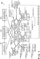
- Fig. 1 is a view showing an arrangement example of the power information management system 100.
- the power information management system 100 includes a power system management server SV1, a charger/discharger management server SV2 functioning as a power information management apparatus, and an electric vehicle management server SV3 (to be also referred to as an "EV management server SV3" hereinafter).
- the power system management server SV1, the charger/discharger management server SV2 (a power information management apparatus), and the EV management server SV3 are separated apparatuses, but they may also be integrated into one information processing apparatus. It is also possible to integrate the charger/discharger management server SV2 (a power information management apparatus) with the power system management server SV1 or the EV management server SV3.
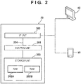
- Fig. 2 is a block diagram showing the basic arrangement of each server.
- Fig. 2 shows the charger/discharger management server SV2 (a power information management apparatus) as a typical example of the servers.
- the charger/discharger management server SV2 includes a control unit 201 such as a CPU that functions as a processing unit, a storage unit 202 including a RAM 202A, a ROM 202B, and the like, and an I/F unit 203 functioning as a communication unit for communicating with an external device.
- These blocks shown in Fig. 2 are connected to each other via a system bus 204 so that they can communicate with each other.
- the I/F unit 203 (a communication unit) can communicate with a plurality of chargers/dischargers (101, 102,..., n) connected to power system networks PG1 and PG2 and external devices across a network.
- These external devices include an electric vehicle EV having a communication apparatus, in addition to the power system management server SV1 and the EV management server SV3.
- the RAM 202A of the storage unit 202 functions as an arithmetic processing area of the control unit 201, and can store information obtained via the I/F unit 203 (a communication unit) and the results of arithmetic operations processed by the control unit 201.
- the ROM 202B functions as a storage area for storing various programs for the control unit 201 to perform processing.
- a display device 40 and a portable information terminal device 50 as an input device can be connected to the charger/discharger management server SV2. This makes it possible to set parameters for arithmetic processing from the information terminal device 50, and provide information to the user by displaying the arithmetic results on the display device 40.
- the control unit 201 executes the various programs stored in the ROM 202B, determines allocation for guiding a plurality of electric vehicles (EV1, EV2,..., EVn) to the chargers/dischargers (104,..., n) connected to the power system network PG2 in a blackout state, and performs information processing for providing route information for guiding each electric vehicle to the charger/discharger (104,..., n) based on the determined allocation.
- the control unit 201 updates the generation and change of the route information for guiding the electric vehicle to each charger/discharger in real time, and distributes the route information to each electric vehicle.
- the charger/discharger management server SV2 communicates with the plurality of chargers/dischargers (101, 102,..., n) connected to the power system networks PG1 and PG2 via the I/F unit 203 (a communication unit), and obtains position information of the plurality of chargers/dischargers (101, 102,..., n), and information indicating the availability of each charger/discharger, as charger/discharger state information.
- the position information of the plurality of chargers/dischargers contains information of the power system network to which each charger/discharger is connected, the installation position of the charger/discharger, and an area or a place (for example, shelter 1 or 2) to which the charger/discharger can supply electric power.
- the power system network PG1 is in a normal state, and the chargers/dischargers 101, 102, and 103 are connected to the power system network PG1.
- the charger/discharger 101 is in an available state in which no electric vehicle EV is connected.
- the electric vehicles EV1 and EV2 are respectively connected to the chargers/dischargers 102 and 103, so the chargers/dischargers 102 and 103 are in a charging state. Furthermore, the power system network PG2 is in a blackout state, and the chargers/dischargers 104 and n are connected to the power system network PG2.
- the control unit 201 determines allocation for guiding an electric vehicle (EV2 in this example shown in Fig. 1 ), among the plurality electric vehicles, to the charger/discharger 104 connected to the power system network PG2 in a blackout state, and performs information processing for providing route information for guiding the electric vehicle EV2 to the charger/discharger 104 based on the determined allocation.
- EV2 electric vehicle
- Fig. 1 the electric vehicle
- the control unit 201 determines allocation for guiding an electric vehicle (EV2 in this example shown in Fig. 1 ), among the plurality electric vehicles, to the charger/discharger 104 connected to the power system network PG2 in a blackout state, and performs information processing for providing route information for guiding the electric vehicle EV2 to the charger/discharger 104 based on the determined allocation.
- the electric vehicle EV2 charged by the charger/discharger 103 moves along route 1 based on the allocation and connects to the charger/discharger 104, and the charger/discharger 104 is in a discharged state of electric power stored in the battery of the connected electric vehicle EV2.
- This discharging from the charger/discharger 104 supplies electric power to a power demand area (to be also simply referred to as an "area" hereinafter) such as shelter 1.
- the control unit 201 can update the generation and change of route information for guiding an electric vehicle to each charger/discharger in real time and distribute the route information to the electric vehicle. For example, if a closed section is set midway along route 1, the control unit 201 changes the route information in real time, and provides the route information for guiding the electric vehicle EV2 to the charger/discharger 104 based on updated route 2.
- the control unit 201 can also determine the priority of power supply, and perform guidance that changes the destination so that the electric vehicle moves to the charger/discharger n having high priority. If a plurality of areas in the power system network require electric power, the control unit 201 compares the demand powers of these areas, and determines allocation by giving priority to an area having a large demand power. In the example shown in Fig.
- control unit 201 changes the destination from the charger/discharger 104 as the initial destination to the charger/discharger n, and provides route information for guiding the electric vehicle EV2 to the charger/discharger n based on route 3.
- the demand information on the demand side requiring electric power contains information indicating, for example, the position of a shelter (evacuation space), the position of a charger/discharger corresponding to each shelter in a power system network in a blackout state, the amount of electric power required in the power system network (each shelter), the timing at which electric power is necessary, and the blackout restoration status.
- the charger/discharger management server SV2 communicates with the EV management server SV3 via the I/F unit 203, and obtains the positions (the traveling position, the stopping places) of the plurality of electric vehicles, information (the capacity, SOC: State Of Charge) indicating the charged states of the storage batteries of a plurality of electric vehicles, and information indicating the type (for example, large, medium, or small) of each electric vehicle.
- the charger/discharger management server SV2 obtains the positions of a plurality of electric vehicles, information indicating the charged states of the batteries mounted in the plurality of electric vehicles, and information indicating the types of the plurality of electric vehicles.
- the charger/discharger management server SV2 communicates with the EV management server SV3, obtains information (for example, the presence/absence of a closed section) of the route condition of a movement route for guiding an electric vehicle to a charger/discharger, and obtains, as a response (power response) to a power request, information indicating the intention of the user of the electric vehicle with respect to power trading.
- information for example, the presence/absence of a closed section
- the information indicating the intention of the user contains, for example, information indicating that the user intends to charge the battery at low cost in a normal state, information indicating that the user intends to move to an area in a blackout state as a volunteer and discharge (supply) electric power of the battery of the electric vehicle, that is, the user intends to support the blackout area, or information indicating that the user intends to make a profit by discharging electric power of the battery of the electric vehicle when a blackout occurs.
- the charger/discharger management server SV2 communicates with the power system management server SV1 via the I/F unit 203, and obtains state information indicating a state (power system state) showing whether the power system networks PG1 and PG2 are in a normal state or a blackout state.
- state information indicating a state (power system state) showing whether the power system networks PG1 and PG2 are in a normal state or a blackout state.
- the charger/discharger management server SV2 can also obtain information indicating a power request input from a system power company and information of a power trading price or a traveling power price required for an electric vehicle to travel.
- the charger/discharger management server SV2 obtains, as demand information on the demand side requiring electric power, information indicating the position of a shelter, the position of a charger/discharger corresponding to each shelter in the power system network in a blackout state, the amount of electric power required in the shelter, the timing at which electric power is necessary, and the blackout restoration status.
- the information indicating the timing at which electric power is necessary contains, for example, time information that divides one day into time zones, and information of a period over a plurality of days. Also, the information indicating the blackout restoration status contains map-area information combining map information and an area where electric power is supplied.
- the control unit 201 of the charger/discharger management server SV2 compares the supply information on the power supply side with the demand information on the demand side requiring electric power, allocates a plurality of electric vehicles based on the comparison result, and guides the plurality of electric vehicles based on the allocation result.
- the power system management server SV1 has the same basic arrangement as the block diagram shown in Fig. 2 .
- the control unit of the power system management server SV1 monitors the power system networks PG1 and PG2 across the network, and collects state information indicating a state (power system state) showing whether the power system networks PG1 and PG2 are in a normal state or a blackout state.
- the I/F unit of the power system management server SV1 transmits the collected state information indicating the power system state to the charger/discharger management server SV2 (a power information management apparatus).
- the state information contains demand information on the demand side.
- This demand information on the demand side contains information indicating, for example, the position of a shelter, the position of a charger/discharger corresponding to each shelter in the power system network in a blackout state, the amount of electric power required in the shelter, the timing at which electric power is necessary, and the blackout restoration status.
- control unit of the power system management server SV1 obtains information indicating a power request input from the system power company across the network, and transmits the information to the charger/discharger management server SV2.
- This information indicating the power request is information indicating whether the system power company requires electric power in the power system networks PG1 and PG2. For example, if a power shortage occurs in a power system network in a normal state, a power request "exists" is set. Likewise, if a power shortage occurs in a power system network in a blackout state, a power request "exists" is set.
- control unit of the power system management server SV1 obtains information indicating a power trading price (for example, n1 yen in a power system network in a normal state, and n2 yen in a power system network in a blackout state) input from the system power company, and transmits the information to the charger/discharger management server SV2 via the I/F unit.
- a power trading price for example, n1 yen in a power system network in a normal state, and n2 yen in a power system network in a blackout state
- control unit of the power system management server SV1 obtains information of a traveling power price necessary for an electric vehicle to travel (for example, n3 yen as a traveling cost for an electric vehicle to move to a power system network in a normal state or a blackout state), and transmits the information to the charger/discharger management server SV2 via the I/F unit.
- a traveling power price necessary for an electric vehicle to travel for example, n3 yen as a traveling cost for an electric vehicle to move to a power system network in a normal state or a blackout state
- the EV management server SV3 also has the same basic arrangement as the block diagram shown in Fig. 2 .
- the control unit of the EV management server SV3 communicates with the plurality of electric vehicles (EV1, EV2,%) across the network, and obtains the positions (the traveling positions, the stopping places) of the plurality of electric vehicles (EV1, EV2,%), information (the capacity, SOC) indicating the charged states of the storage batteries of the plurality of electric vehicles, and information indicating the type (for example, large, medium, and small) of each electric vehicle.
- These pieces of information obtained by the EV management server SV3 are supply information on the power supply side.
- the I/F unit (a communication unit) of the EV management server SV3 wirelessly communicates with an external server apparatus that provides map information and traffic information, allocates the plurality of electric vehicles to destinations (chargers/dischargers), and obtains information of a route for guiding each electric vehicle to the destination (charger/discharger), map information, and information (to be also referred to as "route information" hereinafter) of a route including a closed section.
- the I/F unit of the EV management server SV3 transmits the collected power-supply-side supply information and route information to the charger/discharger management server SV2 (a power information management apparatus).
- the control unit 201 of the charger/discharger management server SV2 performs, for example, route search from the current positions of the plurality of electric vehicles to the destinations. If the route information indicates that road closure occurs in a partial section, the control unit 201 changes (updates) the route in real time. In this case, the control unit 201 can change the route by selecting a shortest route by using the distance to the destination as a parameter.
- the control unit 201 can generate route information by selecting a route along which the ratio of a flat route or a downhill route is high by avoiding an uphill route based on the map information. Therefore, when the electric vehicle moves from the current position to the charger/discharger as the guidance destination, it is possible to reduce the power consumption in the electric vehicle, and maximally secure electric power that can be supplied.
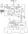
- Fig. 3 is a block diagram of the charger/discharger 101 (a charge/discharge controller) and the electric vehicle EV1 according to the embodiment.
- Fig. 3 shows an example in which the charger/discharger 101 (a charge/discharge controller) controls charging/discharging of a battery 310 of the electric vehicle EV1.
- the electric vehicle EV1 is a plugin hybrid vehicle (PHEV) or the like
- the battery 310 is a lithium-ion battery or the like.
- the charger/discharger 101 can configure a commercial power management apparatus in a charge station, and can also configure a power management apparatus to be installed in a house. At the time of blackout, the charger/discharger 101 may also configure a power management apparatus to be installed in a shelter or the like.
- the charger/discharger 101 (a charge/discharge controller) includes a power line 302a connected to a power system 300 (a power system network). At the time of charging, AC power is supplied to the power line 302a from the power system 300 (a power system network) as a power supply facility such as a system power company. At the time of discharging, the power line 302a outputs AC power to the power system 300 (a power system network).
- a power source 305 is connected to the power line 302a.
- the power source 305 includes, for example, an AC/DC converter and a DC/DC converter, and can perform a predetermined power conversion process during charging/discharging under the control of a control unit 303.
- An external cable 308 is connected, via a relay 307, to a power line 302b connected to the power source 305.
- the external cable 308 is a transmission cable detachably connectable to the electric vehicle EV1.
- the external cable 308 includes a power line 308a for supplying electric power, and a communication line 308b.
- the relay 307 connects and disconnects the power lines 302b and 308a.
- a solar power generator 301 is connected to the charger/discharger 101 (a charge/discharge controller).
- the solar power generator 301 includes a solar cell panel and generates DC power.
- the power source 305 converts electric power generated by the solar power generator 301 into predetermined electric power by the DC/DC converter, and outputs the electric power to the power line 302b, under the control of the control unit 303.
- the power source 305 can convert electric power generated by the solar power generator 301 into predetermined electric power, and output the electric power to the power line 302a, under the control of the control unit 303.
- the charger/discharger 101 (a charge/discharge controller) includes the control unit 303.
- the control unit 303 includes, for example, a processor such as a CPU, a storage device such as a semiconductor memory, and an input/output interface and a communication interface for an external device.
- the storage device stores programs to be executed by the processor, data to be used by the processor to perform processing, and the like.
- the control unit 303 controls the power source 305 and the relay 307. Also, the control unit 303 obtains the detection results of sensors 304a, 304b, and 306.
- the sensor 304a is a sensor for detecting the physical amount of electric power of the power line 302a, and is a sensor for measuring the AC voltage in this embodiment.
- the sensor 304b is a sensor for detecting the physical amount of electric power of the power line 302b, and is a sensor for measuring the DC voltage in this embodiment.
- the sensor 306 is a sensor for detecting the physical amount of electric power generated by the solar power generator 301, and measures the DC voltage generated by the solar power generator 301 in this embodiment.
- the communication line 308b is connected to the control unit 303. When the external cable 308 is connected to the electric vehicle EV1, the control unit 303 includes a communication unit and can communicate with a charge/discharge ECU 311 of the electric vehicle EV1 and the charger/discharger management server SV2.
- the electric vehicle EV1 includes the charge/discharge ECU 311, a battery control unit 312, and a sensor 313 as components related to the battery 310.
- the charge/discharge ECU 311 includes, for example, a processor such as a CPU, a storage device such as a semiconductor memory, and an input/output interface and a communication interface for an external device.
- the charge/discharge ECU 311 can communicate with the control unit 303 of the charger/discharger 101 and the charger/discharger management server SV2 via the communication interface.
- the storage device stores programs to be executed by the processor, data to be used by the processor to perform processing, and the like.
- the charge/discharge ECU 311 controls the battery control unit 312. Also, the charge/discharge ECU 311 obtains the detection result of the sensor 313.
- the sensor 313 is a sensor for detecting the physical amount of electric power of a power line 314 between the battery control unit 312 and the battery 310, and is a sensor for measuring the DC voltage in this embodiment.
- the battery control unit 312 performs charge/discharge control for outputting electric power supplied from the charger/discharger 101 (a charge/discharge controller) to the battery 313, under the control of the charge/discharge ECU 311.
- the battery control unit 312 performs discharge control for outputting electric power stored in the battery 313 to the charger/discharger 101 (a charge/discharge controller).
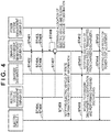
- Fig. 4 is a view showing the processing procedure of the power information processing system 100.
- the power system management server SV1 transmits state information indicating a state (power system state) in which the power system networks PG1 and PG2 are in a normal state or a blackout state. If the power system network is in a blackout state, the state information contains demand information on the demand side. This demand information on the demand side contains information indicating the position of a charger/discharger corresponding to each shelter in the power system network in a blackout state, the amount of electric power necessary for the shelter, the timing at which electric power is necessary, and the restoration status of blackout.
- the power system management server SV1 transmits information (power request information) indicating whether the system power company requires electric power in the power system networks PG1 and PG2 to the charger/discharger management server SV2 (ST403).
- the power system management server SV1 transmits information of the power trading price input from the system power company and the traveling power price required for the electric vehicle to travel to the charger/discharger management server SV2 (ST405).
- the charger/discharger n transmits position information of the charger/discharger and information indicating the availability of the charger/discharger, as charger/discharger state information, to the charger/discharger management server SV2.
- the electric vehicle EVn transmits information indicating the intention of the user of the electric vehicle with respect to power trading, as a response (power response) to the power request (ST404).
- the electric vehicle EVn also transmits the position (the traveling position, the stopping place) of the electric vehicle, information (the capacity, SOC) indicating the charged states of the storage batteries of the plurality of electric vehicles, and information indicating the type of each electric vehicle to the EV management server SV3 (ST406). Then, the EV management server SV3 transmits the information (supply information on the power supply side) obtained from each electric vehicle to the charger/discharger management server SV2.
- the EV management server SV3 obtains map information, traffic information, and information (route information) of a route having a closed section from an external server apparatus, and transmits these pieces of information to the charger/discharger management server SV2 (ST407).
- the control unit 201 determines allocation for guiding the plurality of electric vehicles (EV1, EV2,..., EVn) to the chargers/dischargers (104,..., n) connected to the power system network PG2 in a blackout state based on the demand-side demand information (ST401) and the power-supply-side supply information (ST406), and generates route information for guiding the electric vehicles to the chargers/dischargers (104,..., n) based on the determined allocation. Then, the control unit 201 guides the plurality of electric vehicles based on the generated route information.
- Fig. 5 is a view showing an example of a state in which the pieces of information transmitted to the charger/discharger management server SV2 are stored in the form of a table.
- the data transmission from ST401 to ST407 is sequentially executed at a predetermined timing, and the data in the form of a table shown in Fig. 5 is updated based on the data transmission.
- control unit 201 of the charger/discharger management server SV2 sequentially executes the process of determining allocation of the plurality of electric vehicles, the process of generating route information, and the process of guiding the plurality of electric vehicles, at a predetermined timing in synchronism with the data transmission timing (ST408).
- control unit 201 of the charger/discharger management server SV2 notifies the plurality of electric vehicles of route information (route guidance) for guiding each electric vehicle to the charger/discharger n based on the allocation, and price merit information when the electric vehicle moves to the charger/discharger n in the guidance destination as the destination.
- route guidance route guidance
- price merit information when the electric vehicle moves to the charger/discharger n in the guidance destination as the destination.
- the control unit 201 of the charger/discharger management server SV2 calculates the power trading balance when the electric vehicle n charges or discharges the electric power charged in the battery 310, based on the power trading price.
- the control unit 201 calculates the traveling cost required for the electric vehicle to travel, based on the traveling power price and the traveling distance from the current position to the charger/discharger n as the destination. Then, the control unit 201 notifies the plurality of electric vehicles of the result of subtracting the traveling cost from the trading balance of charge/discharge, as the price merit information. This makes it possible to provide the user of the electric vehicle with information visualizing the power charge/discharge balance and the movement cost, together with the route information resulting from the movement.
- the electric vehicle n moves to the charger/discharger n as the destination and performs charging/discharging.
- the charger/discharger n notifies the charger/discharger management server SV2 of the charging result of the electric vehicle n, and the charger/discharger management server SV2 notifies the power system management server SV1 of the charging result transmitted from the charger/discharger n (ST412).
- the power system management server SV1 performs a power cost adjusting process based on the charging result, and notifies the charger/discharger management server SV2 of the result of the power cost adjustment (ST413).
- the charger/discharger management server SV2 notifies the electric vehicle n of the result of the power cost adjustment transmitted from the power system management server SV1, and terminates the process (ST414).
- Fig. 6 is a flowchart for explaining a practical procedure in ST408.
- the control unit 201 of the charger/discharger management server SV2 obtains state information indicating a state (power system state) in which the power system network is in a normal state or a blackout state.
- the control unit 201 obtains this state information based on the information (ST401 in Fig. 4 ) transmitted from the power system management server SV1.
- the control unit 201 determines whether the target power system network requires electric power, based on the power request information transmitted from the power system management server SV1. If it is determined in ST602 that no electric power is necessary (ST602 - No), the control unit 201 returns the process to ST601, and repetitively executes the same process. If it is determined in ST602 that the target power system network requires electric energy (if a power request "exists" is set in the power request information: ST602 - Yes), the control unit 201 advances the process to ST603.
- the control unit 201 obtains the demand power on the power demand side. Based on the demand information on the demand side requiring electric power, the control unit 201 obtains the demand power.
- the demand information on the demand side contains information indicating the position of a shelter (evacuation area), the position of a charger/discharger corresponding to each shelter in the power system network in a blackout state, the amount of electric power required in the shelter, the timing at which electric power is required, and the blackout restoration status.
- the control unit 201 obtains the supply power on the power supply side.
- the control unit 201 obtains the supply power based on supply information on the power supply side capable of supplying electric power.
- the supply information on the power supply side contains the positions (the traveling positions, the stopping places) of the plurality of electric vehicles, information (the capacity, SOC) indicating the charged states of the storage batteries of the plurality of electric vehicles, and information indicating the type of each electric vehicle.
- control unit 201 determines allocation of the plurality of electric vehicles based on the comparison between the demand power (ST603) and the supply power (ST604). Based on the comparison result, the control unit 201 determines allocation of the plurality of electric vehicles so as to make the demand power and the supply power equal.
- control unit 201 Based on the demand information, the control unit 201 specifies which evacuation area requires how much electric power at that timing in the power system network in a blackout state. In addition, based on the supply information, the control unit 201 can specify the position of each of the plurality of electric vehicles and the power supply capability of the electric vehicle.
- P1 be demand electric power required in a first area (shelter 1) in the power system network PG2 in a blackout state shown in Fig. 1 .
- the supply power of the electric vehicle EV2 is P2
- the supply power of the electric vehicle EV1 is P1 lower than P2.
- the control unit 201 determines allocation such that the electric vehicle EV2 moves to the charger/discharger 104 corresponding to the first area (shelter 1) so as to make the demand power and the supply power equal.
- the control unit 201 compares the demand powers of the plurality of areas (for example, shelters) in the power system network, and determines allocation by giving priority to an area requiring a large demand power. Assume that in the power system network PG2 shown in Fig. 1 , the necessary demand power is P3 in a second area (shelter 2), and the demand power P3 is electric power equal to P1 + P2. In this case, the control unit 201 determines allocation by giving priority to the second area having a large demand power over the first area.
- the control unit 201 can also determine allocation so that the electric vehicle EV3 (the supply power P3) moves to the charger/discharger n corresponding to the second area (shelter 1).
- the control unit 201 determines the number of electric vehicles to be allocated in accordance with the number of chargers/dischargers corresponding to the destination (for example, the second area) as the movement destination. If a plurality of electric vehicles are allocated to one charger/discharger n, a power shortage can occur. In this case, therefore, the control unit 201 determines allocation such that the electric vehicle EV3 (the supply power P3) moves to the charger/discharger n corresponding to the second area (shelter 1) so as to cover the demand power by one electric vehicle.
- the control unit 201 determines allocation such that the electric vehicle EV3 (the supply power P3) moves to the charger/discharger n corresponding to the second area (shelter 1) so as to cover the demand power by one electric vehicle.
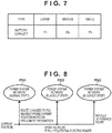
- Fig. 7 is a view showing an example of the relationship between the type of electric vehicle and the battery capacity (supply power) in a fully charged state.
- the control unit 201 determines the allocation so as to select a vehicle type (the electric vehicle EV3) having a large battery capacity in a fully charged state based on the vehicle type information.
- An allocation like this can avoid a power shortage that occurs when an electric vehicle cannot be connected to a charger/discharger, by suppressing a mismatched allocation in which the number of electric vehicles is larger than that of chargers/dischargers corresponding to the destination as the movement destination.
- the control unit 201 determines whether there are a plurality of power system networks requesting electric power. If it is determined in ST606 that there is only one power system network requesting electric power, the control unit 201 advances the process to ST608. On the other hand, if it is determined in ST606 that there are a plurality of power system networks requesting electric power (ST606 - Yes), the control unit 201 advances the process to ST607.
- Fig. 8 is a view for explaining an example in which the allocation of electric vehicles is determined based on price merit information.
- a power system network requesting electric power is sometimes added by later sequential processing.
- the control unit 201 determines the allocation of electric vehicles based on the price merit information.
- the control unit 201 calculates the power trading balance when a plurality of electric vehicles charge/discharge the batteries, and the traveling cost required for traveling of the plurality of electric vehicles based on the traveling power price, and calculates the price merit information as a result of subtracting the traveling cost from the trading balance resulting from charging/discharging. Then, the control unit 201 determines the allocation of electric vehicles so as to maximize the price merit information. Since the traveling cost can be reduced by shortening the traveling distance, the control unit 201 determines the allocation of electric vehicles by giving priority to a power system network nearest to the current position. For example, based on the comparison of the power system networks PG1 to PG3 shown in Fig. 8 , the control unit 201 determines the allocation of electric vehicles by giving priority to the power system network PG1 nearest to the current position.
- the priority of the power system network PG3 in a blackout state can be set to be higher than that of the power system network PG1 in a normal state.
- the control unit 201 can determine the allocation of electric vehicles by setting a high priority for the power system network PG3 in a blackout state, which is positioned at a long distance compared to the power system network PG1 in a normal state.
- control unit 201 can set the cost required for the charging to 0. This can promote discharging to a power system network in a blackout state.
- the control unit 201 In ST608, the control unit 201 generates route information for guiding each electric vehicle to a charger/discharger based on the allocation determined in ST605. Then, the control unit 201 guides each of the plurality of electric vehicles based on the generated route information. Based on information of the route condition of the movement route for guiding each electric vehicle to a charger/discharger, the control unit 201 updates the route information in real time and distributes the information to each electric vehicle. For example, if a closed section is set midway along initially set route 1 (the movement route), the control unit 201 updates the route information in real time, and guides each of the plurality of electric vehicles based on updated route 2 (the movement route).
- the control unit 201 generates route information (route 3) for guiding an electric vehicle to the changed guidance destination, and guides each of the plurality of electric vehicles based on the generated route information (route 3).
- the control unit 201 provides the generated route information (route 3) to the electric vehicle EV2 and guides it to the changed guidance destination.
- the power information processing method of Arrangement 18 can allocate and guide an electric vehicle as the supply side to the demand side of a power system network requiring electric power.
Landscapes
- Engineering & Computer Science (AREA)
- Power Engineering (AREA)
- Transportation (AREA)
- Mechanical Engineering (AREA)
- Business, Economics & Management (AREA)
- General Physics & Mathematics (AREA)
- Physics & Mathematics (AREA)
- Accounting & Taxation (AREA)
- Finance (AREA)
- Sustainable Development (AREA)
- Sustainable Energy (AREA)
- Life Sciences & Earth Sciences (AREA)
- Theoretical Computer Science (AREA)
- Strategic Management (AREA)
- General Business, Economics & Management (AREA)
- Development Economics (AREA)
- Economics (AREA)
- Charge And Discharge Circuits For Batteries Or The Like (AREA)
- Electric Propulsion And Braking For Vehicles (AREA)
- Supply And Distribution Of Alternating Current (AREA)
- Traffic Control Systems (AREA)
- Management, Administration, Business Operations System, And Electronic Commerce (AREA)
- Remote Monitoring And Control Of Power-Distribution Networks (AREA)
Applications Claiming Priority (1)
| Application Number | Priority Date | Filing Date | Title |
|---|---|---|---|
| JP2020058228A JP7460421B2 (ja) | 2020-03-27 | 2020-03-27 | 電力情報処理装置、電力情報処理システム、および電力情報処理方法 |
Publications (2)
| Publication Number | Publication Date |
|---|---|
| EP3885181A1 true EP3885181A1 (de) | 2021-09-29 |
| EP3885181B1 EP3885181B1 (de) | 2026-03-04 |
Family
ID=74946992
Family Applications (1)
| Application Number | Title | Priority Date | Filing Date |
|---|---|---|---|
| EP21162915.9A Active EP3885181B1 (de) | 2020-03-27 | 2021-03-16 | Leistungsinformationverarbeitungsvorrichtung, leistungsinformationverarbeitungssystem und leistungsinformationverarbeitungsverfahren |
Country Status (3)
| Country | Link |
|---|---|
| US (1) | US11993172B2 (de) |
| EP (1) | EP3885181B1 (de) |
| JP (1) | JP7460421B2 (de) |
Families Citing this family (3)
| Publication number | Priority date | Publication date | Assignee | Title |
|---|---|---|---|---|
| JP7276305B2 (ja) * | 2020-11-17 | 2023-05-18 | トヨタ自動車株式会社 | 情報作成装置、情報作成プログラム及び給電制御システム |
| US20230115083A1 (en) * | 2021-10-13 | 2023-04-13 | Fermata Energy Llc | Methods of using bidirectional charging to supply back-up power and increase resiliency of powered networks |
| JP7658350B2 (ja) | 2022-09-13 | 2025-04-08 | トヨタ自動車株式会社 | 情報処理システムおよび情報処理方法 |
Citations (3)
| Publication number | Priority date | Publication date | Assignee | Title |
|---|---|---|---|---|
| JPS5529894B2 (de) | 1972-10-12 | 1980-08-07 | ||
| JP2007252117A (ja) | 2006-03-16 | 2007-09-27 | Chugoku Electric Power Co Inc:The | 電力供給システムおよび電力供給方法 |
| US20120249068A1 (en) * | 2009-12-24 | 2012-10-04 | Hitachi Ltd | Power Grid Control System Using Electric Vehicle, Power Grid Control Apparatus, Information Distribution Apparatus, and Information Distribution Method |
Family Cites Families (11)
| Publication number | Priority date | Publication date | Assignee | Title |
|---|---|---|---|---|
| JP5569064B2 (ja) | 2010-03-16 | 2014-08-13 | トヨタ自動車株式会社 | 車両経路案内装置 |
| KR101655467B1 (ko) | 2010-06-23 | 2016-09-08 | 현대자동차주식회사 | 차량용 길 안내 시스템 |
| CN108082002B (zh) * | 2012-02-13 | 2021-06-22 | 埃森哲环球服务有限公司 | 用于电力跟踪和电力分配的分布式智能的方法和系统 |
| JP5894845B2 (ja) | 2012-04-16 | 2016-03-30 | ツネイシホールディングス株式会社 | 電力供給方法及び電力供給システム |
| JP2014236602A (ja) | 2013-06-03 | 2014-12-15 | 株式会社東芝 | 複数蓄電池の複数目的制御装置、複数目的制御システム及びプログラム |
| EP3118962A4 (de) | 2014-03-12 | 2017-11-01 | Nec Corporation | Speicherbatterieteilungssystem, informationsverarbeitungsvorrichtung, speicherbatterieteilungsverfahren und aufzeichnungsmedium zur aufzeichnung eines speicherbatterieteilungsprogramms |
| US9987940B2 (en) * | 2014-09-16 | 2018-06-05 | Honda Motor Co., Ltd. | Priority based vehicle control strategy |
| JP2017112806A (ja) | 2015-12-18 | 2017-06-22 | トヨタホーム株式会社 | 災害時給電システム |
| JP7163001B2 (ja) | 2016-03-03 | 2022-10-31 | 三菱重工業株式会社 | 電力マネジメント装置及び電力マネジメント方法並びにロジスティクスネットワークシステム |
| DE102016114081A1 (de) * | 2016-07-29 | 2018-02-01 | Proton Motor Fuel Cell Gmbh | Brennstoffzellensystem und Verfahren zum Betrieb eines Brennstoffzellensystems |
| EP3718073A4 (de) * | 2017-12-01 | 2021-08-25 | California Institute of Technology | Optimierungsrahmenwerk und verfahren zur adaptiven ev-aufladung |
-
2020
- 2020-03-27 JP JP2020058228A patent/JP7460421B2/ja active Active
-
2021
- 2021-03-15 US US17/201,213 patent/US11993172B2/en active Active
- 2021-03-16 EP EP21162915.9A patent/EP3885181B1/de active Active
Patent Citations (3)
| Publication number | Priority date | Publication date | Assignee | Title |
|---|---|---|---|---|
| JPS5529894B2 (de) | 1972-10-12 | 1980-08-07 | ||
| JP2007252117A (ja) | 2006-03-16 | 2007-09-27 | Chugoku Electric Power Co Inc:The | 電力供給システムおよび電力供給方法 |
| US20120249068A1 (en) * | 2009-12-24 | 2012-10-04 | Hitachi Ltd | Power Grid Control System Using Electric Vehicle, Power Grid Control Apparatus, Information Distribution Apparatus, and Information Distribution Method |
Also Published As
| Publication number | Publication date |
|---|---|
| JP7460421B2 (ja) | 2024-04-02 |
| EP3885181B1 (de) | 2026-03-04 |
| US20210300202A1 (en) | 2021-09-30 |
| JP2021158837A (ja) | 2021-10-07 |
| US11993172B2 (en) | 2024-05-28 |
Similar Documents
| Publication | Publication Date | Title |
|---|---|---|
| US11920947B2 (en) | Notification controller and electrically powered vehicle | |
| EP2683048B1 (de) | Ladestromsteuerungssystem | |
| EP3885181B1 (de) | Leistungsinformationverarbeitungsvorrichtung, leistungsinformationverarbeitungssystem und leistungsinformationverarbeitungsverfahren | |
| Jiang et al. | Decentralized scheduling of PEV on-street parking and charging for smart grid reactive power compensation | |
| EP3943336B1 (de) | Verfahren zur steuerung des leistungsempfangs für leistungsspeicherelement und vorrichtung zur steuerung des leistungsempfangs | |
| US20130271080A1 (en) | Charging system and charging method | |
| EP3944453A1 (de) | Verfahren zur steuerung der leistungsaufnahme von leistungsaufnahmeelementen und vorrichtung zur steuerung der leistungsaufnahme | |
| CN114725922A (zh) | 电力管理系统、服务器以及电力供需的调节方法 | |
| CN106985696A (zh) | 分布式移动充/换电车系统和储能式充电桩总成 | |
| KR20230032024A (ko) | 전기자동차의 전기 사용 안내 방법 | |
| JP2022184645A (ja) | 制御装置、電力システムおよびプログラム | |
| JP2020077026A (ja) | 位置情報提供システム | |
| EP4262046B1 (de) | Fahrzeug und kommunikationssteuerungsverfahren dafür | |
| JP2023013709A (ja) | 電力管理システム、電力管理サーバ、および、電力管理方法 | |
| JP7655149B2 (ja) | 制御装置、サーバおよびプログラム | |
| JP2025131711A (ja) | 充放電システム、充放電システムの制御方法、およびコンピュータプログラム | |
| Dicorato et al. | Performance analysis of EV stations optimal operation in DC microgrid configurations | |
| US12344106B2 (en) | Method for providing vehicle charging service, and vehicle charging system | |
| JP2021197765A (ja) | 配車システム | |
| Santhoshi et al. | Advancements in fast charging systems for electric vehicles | |
| Secchi et al. | FLOW's D1. 2-Baseline: Scenarios and definitions | |
| US20250337246A1 (en) | Balance control generator | |
| US20250249773A1 (en) | Electric vehicle charging system and method of operating the same | |
| CN120013398A (zh) | 配送计划的生成方法 | |
| CN115707590A (zh) | 配车装置及配车方法 |
Legal Events
| Date | Code | Title | Description |
|---|---|---|---|
| PUAI | Public reference made under article 153(3) epc to a published international application that has entered the european phase |
Free format text: ORIGINAL CODE: 0009012 |
|
| STAA | Information on the status of an ep patent application or granted ep patent |
Free format text: STATUS: REQUEST FOR EXAMINATION WAS MADE |
|
| 17P | Request for examination filed |
Effective date: 20210316 |
|
| AK | Designated contracting states |
Kind code of ref document: A1 Designated state(s): AL AT BE BG CH CY CZ DE DK EE ES FI FR GB GR HR HU IE IS IT LI LT LU LV MC MK MT NL NO PL PT RO RS SE SI SK SM TR |
|
| STAA | Information on the status of an ep patent application or granted ep patent |
Free format text: STATUS: EXAMINATION IS IN PROGRESS |
|
| 17Q | First examination report despatched |
Effective date: 20220602 |
|
| RAP3 | Party data changed (applicant data changed or rights of an application transferred) |
Owner name: HONDA MOTOR CO., LTD. |
|
| GRAP | Despatch of communication of intention to grant a patent |
Free format text: ORIGINAL CODE: EPIDOSNIGR1 |
|
| STAA | Information on the status of an ep patent application or granted ep patent |
Free format text: STATUS: GRANT OF PATENT IS INTENDED |
|
| INTG | Intention to grant announced |
Effective date: 20251009 |
|
| GRAS | Grant fee paid |
Free format text: ORIGINAL CODE: EPIDOSNIGR3 |
|
| GRAA | (expected) grant |
Free format text: ORIGINAL CODE: 0009210 |
|
| STAA | Information on the status of an ep patent application or granted ep patent |
Free format text: STATUS: THE PATENT HAS BEEN GRANTED |
|
| AK | Designated contracting states |
Kind code of ref document: B1 Designated state(s): AL AT BE BG CH CY CZ DE DK EE ES FI FR GB GR HR HU IE IS IT LI LT LU LV MC MK MT NL NO PL PT RO RS SE SI SK SM TR |
|
| REG | Reference to a national code |
Ref country code: CH Ref legal event code: F10 Free format text: ST27 STATUS EVENT CODE: U-0-0-F10-F00 (AS PROVIDED BY THE NATIONAL OFFICE) Effective date: 20260304 Ref country code: GB Ref legal event code: FG4D |
|
| REG | Reference to a national code |
Ref country code: DE Ref legal event code: R096 Ref document number: 602021049059 Country of ref document: DE |
|
| REG | Reference to a national code |
Ref country code: IE Ref legal event code: FG4D |
|
| PGFP | Annual fee paid to national office [announced via postgrant information from national office to epo] |
Ref country code: DE Payment date: 20260226 Year of fee payment: 6 |