EP3885232A1 - Eisenbahndrehgestell mit einem spurwechselsystem und schienenfahrzeug mit einem solchen eisenbahndrehgestell - Google Patents
Eisenbahndrehgestell mit einem spurwechselsystem und schienenfahrzeug mit einem solchen eisenbahndrehgestell Download PDFInfo
- Publication number
- EP3885232A1 EP3885232A1 EP20290031.2A EP20290031A EP3885232A1 EP 3885232 A1 EP3885232 A1 EP 3885232A1 EP 20290031 A EP20290031 A EP 20290031A EP 3885232 A1 EP3885232 A1 EP 3885232A1
- Authority
- EP
- European Patent Office
- Prior art keywords
- bogie
- movable
- frames
- gauge
- rail
- Prior art date
- Legal status (The legal status is an assumption and is not a legal conclusion. Google has not performed a legal analysis and makes no representation as to the accuracy of the status listed.)
- Granted
Links
Images



Classifications
-
- B—PERFORMING OPERATIONS; TRANSPORTING
- B61—RAILWAYS
- B61F—RAIL VEHICLE SUSPENSIONS, e.g. UNDERFRAMES, BOGIES OR ARRANGEMENTS OF WHEEL AXLES; RAIL VEHICLES FOR USE ON TRACKS OF DIFFERENT WIDTH; PREVENTING DERAILING OF RAIL VEHICLES; WHEEL GUARDS, OBSTRUCTION REMOVERS OR THE LIKE FOR RAIL VEHICLES
- B61F7/00—Rail vehicles equipped for use on tracks of different width
Definitions
- the present invention concerns a railway bogie equipped with a gauge varying system, and a railway vehicle comprising such bogie.
- a bogie is a component of a railway vehicle which is provided with sets of wheels and carries the carbody of the vehicle above the rails.
- bogies are designed for railway lines having a standard or main reference gauge; for example, in central Europe the predominant standard gauge measures 1,435 mm.
- railway lines have different gauges; for example, in topographically challenging area, such as mountains, smaller gauges are sometimes used, e.g. gauges of 1,000 mm, usually referred to as the metric gauge.
- patent document CH 703 173 A2 describes a solution where a bogie comprises two half frames supporting each a corresponding set of wheels, and wherein their mutual distance can be varied by means of two lateral arms protruding laterally outside the aligned set of wheels.
- the present invention is aimed at providing a solution for railway bogies equipped with a gauge varying systems, which is suitable to face and at least partially mitigate at least some of the above mentioned issues and shortcomings.
- a bogie for a railway vehicle comprising:
- the bogie may comprise one or more of the following features, which may be combined in any technical feasible combination:
- a railway vehicle comprising at least one bogie of the type above indicated, as per description hereinafter detailed, and in particular as defined in the attached relevant claims.
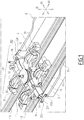
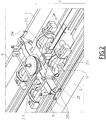
- FIGS 1-4 illustrate a bogie for a railway vehicle, indicated by the overall reference number 100, and therein shown in successive positions.
- the bogie 100 comprises at least a first half-frame 10 carrying a first set of wheels 11, and a second half-frame 20 carrying a second set of wheels 12.
- first half frame 10 and the second half-frame 11 are connected to each other, in a mutual movable manner at least along a first axis (Y) transversal with respect to a travelling direction (X) of the bogie 100 along a railway line.
- the railway line is schematically represented by the illustrated couple of rails, and hereinafter it is referred to as the railway line 110.
- first and second half-frames 10 and 20 are movably connected to each other by means of at least one telescopic bar 15.
- the bogie 100 comprises a first telescopic bar 15 and a second substantially identical telescopic bar 25 (only partially visible in figures 2-4 ), which are positioned, with reference to the travel direction (X), on a front part and on a rear part of a transverse bolster 30 of the bogie 100.
- the transverse bolster 30 is suitable to be connected to a carbody (not illustrated in the figures) of a railway vehicle; for example, according to solutions well known in the art and therefore not described herein in details, the connection is realized using one or more suspensions comprising, inter alia, an air spring 31 and a coupling pivot 32 positioned at the central part of the bolster 30.
- the transverse bolster 30 is movable, together with the carbody once connected therewith, between a lowered position ( figure 1 ) where the bolster 30 rests on and is locked to the first and second half-frames 10, 20 at a first mutual position thereof, and a raised position (see figures 2-4 ) where it is unlocked from and is lifted above the first and second half-frames 10, 20 from the first mutual position.
- the bolster 30 is in lowered position and is locked to the first and second half-frames 10, 20 at the first mutual distance corresponding to a first rail gauge y1; in particular, the first and second half-frames 10 and 20 are spaced along the first axis Y of a first mutual distance corresponding to the first rail gauge y1 (depicted in figure 2 ) which in this case is for example the metric gauge.
- the transverse bolster 30 can be anchored with the two half frames 10 and 20 by mutually engaging anchoring means which are provided on the two half frames 10 and 20 and along the body of the transverse bolster 30 itself, at different positions corresponding to different possible rail gauges.
- the bogie 100 further comprises a gauge varying system suitable to interact mechanically, while the bogie is travelling along the railway line 110, with a gauge varying installation, indicated by the overall reference number 1 in figure 2 , which is positioned along the railway line 110.
- the installation 1 comprises for example a first lateral supporting rail 2 and a second lateral supporting rail 3, which are parallel and substantially identical to each other, and which, when seen on a side view, present both a profile whose height varies along the travelling direction (X), and in particular with an initial rising ramp, indicated in figure 1 by the reference number 8, and a decreasing ramp towards the final end of the installation, indicated in figure 4 by the reference number 9.
- the intermediate portion between the two ramps 8 and 9 can be straight at the same maximum height of the initial ramp 8.
- the exemplary installation 1 illustrated further comprises a plurality of guiding rails which are interposed between the first and second supporting rails 2 and 3 and which extend along the travelling direction (X) of the bogie 100.
- the plurality of guiding rails of the installation 1 comprises a first couple of mutually associated rails, namely a first guiding rail 4 and a second guiding rail 5, and a second couple of mutually associated guiding rails, namely a third guiding rail 6 and a fourth guiding rail 7; the first and second guiding rails 4 and 5 are positioned between the third and fourth guiding rails 6 and 7.
- the gauge varying system of the bogie 100 comprises at least actuating means, indicated in figure 5 by the overall reference number 220, and a plurality of movable guided elements 201, 202, 203, 204, wherein the movement of the transverse bolster 30 from the lowered position to the raised position triggers the actuating means 220 which then actuate the plurality of movable guided elements to move from a rest position to a working position at which each guided element 201, 202, 203 and 204 is brought to slide inside and is guided by a corresponding guiding rail 4, 5, 6, 7 of the installation 1.
- the actuating means 220 are hydraulic actuating means which actuate hydraulically the plurality of movable guided elements to move from the rest position to the working position as above indicated.
- each guided element 201, 202, 203, 204 is guided to slide inside and to follow the profile of the corresponding guiding rails 4, 5, 6 and 7 which extend in the travel direction (X); in this way, there is a displacement of at least one of the first and second half-frames 10 and 20 along the first axis (Y) transversal to the travelling direction (X) of the bogie 100 up to when a second mutual distance between the first and second half-frames 10 and 20 is reached.
- This second mutual distance corresponds to a second rail gauge y2.
- the various guided elements 201, 202, 203 and 204 are positioned and move from the rest position to the working position (and vice-versa) remaining within the space delimited between the first set of wheels 11 and the second set of wheels 12, with reference to the transverse first axis (Y).
- the hydraulic actuating means 220 comprise at least a first elastic element 221 which is triggered by the movement of the transverse bolster 30 from the lowered position to the raised position, and causes the application of hydraulic pressure suitable to move at least some of the movable guided elements 201, 202, 203, 204 from their rest position to their working position.
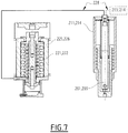
- the hydraulic actuating means 220 further comprise at least a first hydraulic container 225 containing a liquid, such as for example oil, and the at least a first elastic element 221 comprises a first spring 221 housed inside the first hydraulic container 225 and configured to pass from a pre-compressed position (illustrated in figure 6 ), when the transverse bolster 30 is in the lowered position, to an extended position (illustrated in figure 7 ) when the transverse bolster 30 is lifted towards the raised position, thus causing the application of the hydraulic pressure suitable to move at least some of the plurality of movable guided elements 201, 202, 203, 204 from the rest position to the working position.
- a pre-compressed position illustrated in figure 6
- an extended position illustrated in figure 7
- the hydraulic actuating means 220 comprise: a second elastic element 222 which is triggered by the movement of the transverse bolster 30 from the lowered position to the raised position to cause the application of hydraulic pressure suitable to move at least some of the movable guided elements from their rest position to their working position; and a second hydraulic container 226 containing a liquid, such as for example oil, wherein the second elastic element 222 comprises a second spring 222 housed inside the second housing container 226.
- the second spring 222 is configured to pass from a pre-compressed position, when the transverse bolster 30 is in the lowered position, to an extended position when the transverse bolster 30 is lifted towards the raised position, thus causing, by means of the contained liquid, the application of the hydraulic pressure suitable to move at least some of the plurality of movable guided elements from the rest position to the working position.
- the plurality of movable guided elements comprises at least a couple of pivots, for example a first pivot 201 and an associated second pivot 202 which are mounted in a first housing cylinder 211 and in a corresponding second housing cylinder 212, respectively; in particular, the first and second pivots 201 and 202 are movable along a substantially vertical second axis (Z) transversal to both the first axis (Y) and to the travelling direction (X), between the rest position where they are each at least partially retracted inside the respective first and second cylinders 211 and 212, as visible in figure 6 , and the working position where they are each at least partially extracted outside the respective first and second cylinders 211 and 212, as visible in figure 7 , in order to enter into the associated guiding rails 4 and 5 of the installation 1; as partially illustrated in figures 3-4 .
- first pivot 201 and an associated second pivot 202 which are mounted in a first housing cylinder 211 and in a corresponding second housing cylinder 212, respectively; in particular, the
- the plurality of movable guided elements further comprises a second couple of pivots, for instance a third pivot 203 and an associated fourth pivot 204 which are mounted in a third housing cylinder 213 and in a corresponding fourth housing cylinder 214, respectively; in particular, the third and fourth pivots 203 and 204 are also movable along the mentioned substantially vertical second axis (Z) transversal to both the first axis (Y) and to the travelling direction (X), between the rest position where they are each at least partially retracted inside the respective third and fourth housing cylinders 213 and 214, and the working position where they are each at least partially extracted outside the respective third and fourth housing cylinders 213 and 214, in order to enter each into an associated guiding rail 5 and 6 of the installation 1.
- a second couple of pivots for instance a third pivot 203 and an associated fourth pivot 204 which are mounted in a third housing cylinder 213 and in a corresponding fourth housing cylinder 214, respectively; in particular, the third and fourth pivots 203 and 204
- the first and third housing cylinders 211 and 213 are in hydraulic communication, via one or more cables 228, with the first hydraulic container 225 housing the first spring 221 which, when triggered following the lifting of the transverse bolster 30, causes, by means of the contained liquid, the application of hydraulic pressure to both the first and third pivots 201 and 203, which are actuated to move from their rest position to their working position.
- the third and fourth cylinders 213 and 214 are in hydraulic communication, via one or more cables 228, with the second hydraulic container 226 housing the second spring 222 which, when triggered following the lifting of the transverse bolster 30, causes the application of hydraulic pressure to both the second and fourth pivots 202 and 204, which are actuated to move from their rest position to their working position.
- the retracted and extended positions of the second and fourth pivots 202 and 204 are substantially the same positions illustrated for the first and third pivots 201 and 203 illustrated in figures 6 and 7 , respectively.
- the solution devised in the present invention allows a high degree of flexibility in realizing various different alternatives; for example, the first hydraulic container 225 housing the first spring 221 can be in hydraulic communication with the first and second housing cylinders 211 and 212 via one or more cables 228a, illustrated with dotted lines in figure 5 , and when triggered following the lifting of the transverse bolster 30, they can cause the actuation of the first and second pivots 201 and 202 to move from their rest position to their working position.
- the second hydraulic container 226 housing the second spring 222 can be in hydraulic communication with the third and fourth housing cylinders 213 and 214 via one or more similar cables 228a, and when triggered following the lifting of the transverse bolster 30, they can cause the actuation of the third and fourth pivots 203 and 204 to move from their rest position to their working position.
- the first and second cylinders 211 and 212, together with their respective first and second pivots 201, 202, are installed along the first telescopic bar 15 which interconnects the first and second half frames 10, 20 along the transverse direction (Y), at a front part of the transverse bolster 30, as for example illustrated in figures 1-4 .
- the third and fourth cylinders 213 and 214, together with their respective third and fourth pivots 203 and 204, are installed along the second telescopic bar 25 which interconnects the first and second half frames 10, 20 along the transverse direction (Y), at a rear part of the transverse bolster 30, as for example partially visible in figures 1-4 .
- the first and second housing cylinders 211 and 212 are installed along the first telescopic bar 15 so that the first and second pivots 201, 202 housed therein are spaced apart from each other of a first distance measured along the first transverse axis (Y) and with reference to their axes; in turn, the third and fourth housing cylinders 213 and 214 are installed along the second telescopic bar 25 so that the third and fourth pivots 203 and 204 housed therein are spaced apart from each other of a second distance measured along the same first transverse axis (Y), and with reference to their axes.
- the second distance is longer that said first distance.
- the third and fourth pivots 203 and 204 slide inside and are guided each by the profile of the corresponding guiding rails; in particular, the presence of the four guided pivots 201, 202, 203 and 204 prevents undesired rotations of the bogie 100 around the vertical axis (Z) and ensures a steady movement of the half-frames 10 and 20, thus eliminating, or at least reducing, the likelihood of their jamming.
- the first hydraulic container 225 together with the first spring 221 are at least partially fitted in a space provided between the transverse bolster 30 and the first half-frame 10, e.g. towards the first end 33 of the transverse bolster 30.
- the second hydraulic container 226 together with the second spring 222 are at least partially fitted in a space provided between the transverse bolster 30 and the second half-frame 20, e.g. towards the second opposite end 34 of the transverse bolster 30, in a configuration symmetric with respect to that illustrated in figure 8 for the first hydraulic container and the related first spring 222.
- first assembly comprising the first hydraulic container 225-first spring 221
- second assembly comprising the second hydraulic 226-second spring 222 are positioned, with respect to the travel direction (X), symmetrically to each other towards the two opposite ends 33 and 34 of the transverse bolster 30.
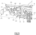
- the gauge varying system further comprises lifting means, indicated in figures 8 and 9 by the overall reference number 250, which are configured to interact, when the bogie 100 is travelling, with the first and the second supporting rails 2 and 3, respectively, and thus to cause the transverse bolster 30 to be lifted from the lowered position to the raised position.
- the lifting means 250 comprise a first swiveling arm 251 carrying at least a first resting element and a second swiveling arm 252 carrying at least a second resting element, wherein the first and second swiveling arms 251 and 252 are provided at the first side end 33 and at the second opposite side end 34 of the transverse bolster 30, respectively.
- the at least a first resting element comprises at least a couple of rollers 253 pivotally hinged onto the first swiveling arm 251, and the second resting element comprises at least another couple of rollers 254 pivotally hinged onto the second swiveling arm 252.
- the presence of at least a couple of rollers for each swiveling arm guarantees mechanical redundancy, and as a whole a more controllable supporting force and a more reliable transverse guidance.
- the first swiveling arm 251 is hinged at the first side end 33 of the transverse bolster 30, reversibly movable between a retracted position towards the body of transverse bolster 30, as illustrated in figure 8 , and an extracted position where it is swiveled away from the transverse bolster 30, as illustrated in figure 9 ; in this extracted position, the first resting element, and in particular the first couple of rollers 253 are brought each to rest on and move relative to the first supporting rail 2 of the installation 1, as illustrated in figures 1-4 .
- Each resting element is devised to provide redundancy and at least a degraded mode in which it still rolls on the corresponding supporting rail in case a part of the resting element breaks.
- At least one of the swiveling arms 251, 252, preferably both, are configured to rotate at least around the first axis (Y) transversal to the travelling direction (X) so that the respective first and second resting elements 253 and 254 are always in contact with the corresponding supporting rails 2 and 3, notably while they are travelling, and in particular rolling on the rising and descending parts 8, 9 of the rails 2, 3 themselves.
- At least one of the swiveling arms 251, 252, preferably both, are also configured to rotate around the axis defined by the travelling direction (X) thus providing a further degree of movement.
- the second swiveling arm 252 is hinged at the second opposite end 34 of the transverse bolster 30, reversibly movable between a retracted position (equivalent to that illustrated in figure 8 for the first swiveling arm 251) towards the body of transverse bolster 30, and an extracted position where it is swiveled away from the transverse bolster 30, equivalent to that illustrated in figure 9 for the first swiveling arm 251; in this extracted position, the second resting element, and in particular the second couple of rollers 254 are brought each to rest on and move relative to the second supporting rail 3 of the installation 1, as illustrated in the figures 1-4 .
- the lifting means 250 comprise a first actuating mechanism and a second actuating means for actuating the first swiveling arm 251 and respectively the second swiveling arm 252 to move between the respective retracted position and the extracted position above indicated.
- the first and second actuating mechanisms are substantially identical to each other and are positioned, symmetrically with respect to the travelling direction (X), at the two opposite ends 33 and 34 of the transverse bolster 30; hence, in the relevant figures, for the sake of simplicity, only the first actuating means, positioned at the first end 33 of the bolster 30, are illustrated and will be described herein.
- the first actuating mechanism comprises: an actuating piston 260 which is connected to the first swiveling arm 251 and is partially housed inside a cylinder 261 wherein there could be housed also an associated return spring 262; a looking/unlocking lever 263, for example elbow-shaped, which is hinged on the transverse bolster 30, spaced apart from the first swiveling arm 251, and is provided with a hooking portion 264 suitable to engage a corresponding portion 35 of the bolster and advantageously of the corresponding half-frame 10, in order to lock to/unlock from the lowered position the bolster 30 itself and notably to lock to/unlock from the retracted position the corresponding swiveling arm; and an interconnecting lever 265, e.g.
- a curved lever which interconnects the first swiveling arm 251 with the looking/unlocking lever 263.
- the interconnecting lever 265, the first swiveling arm 251, the piston 260, and the looking/unlocking 263 move solidly together when the first actuating mechanism is activated, for example by an operator.
- the second actuating mechanism positioned on the opposite end 34 of the transverse bolster 30, comprises the same components working substantially in the same manner, namely a second actuating piston 260 which is partially housed inside a second cylinder 261 together with a second return spring 262, and which is connected to the second swiveling arm 252; a second looking/unlocking 263 which is hinged on the transverse bolster 30, spaced apart from the second swiveling arm 252, and is provided with a respective hooking portion 264 suitable to engage a corresponding portion 35 of the bolster 30 and advantageously of the corresponding half-frame 20 in order to lock to/unlock from the lowered position the bolster 30 itself and notably to lock to/unlock from the retracted position the corresponding swiveling arm; and a second interconnecting lever 265, e.g.
- a curved lever which interconnects the second swiveling arm 252 with the second elbow-shaped lever 263, with the second interconnecting lever 265, the second arm 252 and the second elbow-shaped lever 263 which move solidly together when the second actuating mechanism is activated, together with the first actuating mechanism, for example by an operator.
- an operator for example on board the vehicle itself, can activate the lifting means 250, and in particular its first and second actuating means, for example by means of any suitable control system.
- each actuating piston 260 by sliding causes the swiveling of the first and second swiveling arms 251 and 252 which move from their retracted position illustrated in figure 8 to the extracted position illustrated in figure 9 .
- first and second springs 221 and 222 are triggered and, as previously described, cause the application of hydraulic pressure to the first, second, third and fourth pivots 201, 202, 203 and 204 which are actuated to move from the rest position to the working position where they enter each the corresponding guiding rail 4, 5, 6 and 7.
- the lifting means can return from the position illustrated in figure 9 to the position illustrated in figure 8 , where the hooking portions 264 engage each the corresponding portion 35 and thus lock again the transverse bolster 30 in the lowered position
- the bogie 100 according to the present invention allows achieving the intended aim since it allows to modify the gauge while the railway vehicle is travelling along a railway line, in an effective way.
- the solution thus devised does not have components which violate any rail gauge, is mechanically stable and allows proper control of the lateral displacements along the axis (Y) transversal to the travelling direction (X), and which does not cause, or at least substantially minimize, undesired vibrations and rotations around a vertical axis (Z) perpendicular to the travel direction (X).
- the bogie 100 thus conceived is susceptible of modifications and variations, all of which are within the scope of the inventive concept as defined in particular by the appended claims, and contemplates any possible combination of the embodiments or parts thereof hereinbefore described; for example, in relation to the specific application, some of the components or parts described, can be shaped or positioned differently from what described, or there could be a number of components different from that described; the guided pivots 201-204 can move along the second transverse axis (Z), substantially vertically, or they can move along an axis inclined with respect to the vertical direction indicated in the exemplary embodiment illustrated; each elastic element can be associated with and cause the actuation of a different number of guided elements; et cetera.
Landscapes
- Engineering & Computer Science (AREA)
- Mechanical Engineering (AREA)
- Vehicle Body Suspensions (AREA)
- Machines For Laying And Maintaining Railways (AREA)
- Mounting, Exchange, And Manufacturing Of Dies (AREA)
Priority Applications (3)
| Application Number | Priority Date | Filing Date | Title |
|---|---|---|---|
| ES20290031T ES2929332T3 (es) | 2020-03-24 | 2020-03-24 | Bogie ferroviario equipado con un sistema de variación de ancho y vehículo ferroviario que comprende dicho bogie ferroviario |
| EP20290031.2A EP3885232B1 (de) | 2020-03-24 | 2020-03-24 | Eisenbahndrehgestell mit einem spurwechselsystem und schienenfahrzeug mit einem solchen eisenbahndrehgestell |
| JP2021047099A JP2021151859A (ja) | 2020-03-24 | 2021-03-22 | ゲージ変更システムを備えた鉄道台車、およびそのような鉄道台車を備える鉄道車両 |
Applications Claiming Priority (1)
| Application Number | Priority Date | Filing Date | Title |
|---|---|---|---|
| EP20290031.2A EP3885232B1 (de) | 2020-03-24 | 2020-03-24 | Eisenbahndrehgestell mit einem spurwechselsystem und schienenfahrzeug mit einem solchen eisenbahndrehgestell |
Publications (2)
| Publication Number | Publication Date |
|---|---|
| EP3885232A1 true EP3885232A1 (de) | 2021-09-29 |
| EP3885232B1 EP3885232B1 (de) | 2022-08-03 |
Family
ID=70482523
Family Applications (1)
| Application Number | Title | Priority Date | Filing Date |
|---|---|---|---|
| EP20290031.2A Active EP3885232B1 (de) | 2020-03-24 | 2020-03-24 | Eisenbahndrehgestell mit einem spurwechselsystem und schienenfahrzeug mit einem solchen eisenbahndrehgestell |
Country Status (3)
| Country | Link |
|---|---|
| EP (1) | EP3885232B1 (de) |
| JP (1) | JP2021151859A (de) |
| ES (1) | ES2929332T3 (de) |
Cited By (1)
| Publication number | Priority date | Publication date | Assignee | Title |
|---|---|---|---|---|
| CN117799656A (zh) * | 2024-01-22 | 2024-04-02 | 中车青岛四方机车车辆股份有限公司 | 一种轨道列车及其变换轨距装置 |
Citations (5)
| Publication number | Priority date | Publication date | Assignee | Title |
|---|---|---|---|---|
| EP0596408A1 (de) * | 1992-11-06 | 1994-05-11 | Kawasaki Jukogyo Kabushiki Kaisha | Verfahren zum Verändern der Spurweite eines Schienenfahrzeuges, Schienenfahrzeug mit veränderlicher Spurweite und zugehörige Bodeneinrichtung |
| DE10208542A1 (de) * | 2002-02-27 | 2003-09-04 | Siemens Ag | Spurwechselfahrwerk für Schienenfahrzeuge (Stichwort: Schwingenführung) |
| WO2009101023A1 (en) * | 2008-02-13 | 2009-08-20 | Compagnie Du Chemin De Fer Montreux-Oberland Bernois Sa | Bogie for variable rail gauge and changing station of the rail gauge |
| CH703173A2 (de) | 2010-05-21 | 2011-11-30 | Cie Du Chemin De Fer Montreux Oberland Bernois Sa | Umspurbares Drehgestell für Schienenfahrzeuge. |
| WO2020047852A1 (zh) * | 2018-09-05 | 2020-03-12 | 中车唐山机车车辆有限公司 | 地面变轨装置及变轨距系统 |
Family Cites Families (3)
| Publication number | Priority date | Publication date | Assignee | Title |
|---|---|---|---|---|
| JPH11255115A (ja) * | 1998-03-09 | 1999-09-21 | Mizutani Kensetsu Kogyo Kk | 搬送用台車 |
| EP3031693B1 (de) * | 2014-12-11 | 2018-11-21 | Vossloh High Speed Grinding GmbH | Zwangsgespreiztes Fahrgestell für ein Schienenfahrzeug und Schienenfahrzeug mit einem solchen Fahrgestell |
| CN208963076U (zh) * | 2018-09-05 | 2019-06-11 | 中车唐山机车车辆有限公司 | 一种枕梁、转向架及轨道车辆 |
-
2020
- 2020-03-24 ES ES20290031T patent/ES2929332T3/es active Active
- 2020-03-24 EP EP20290031.2A patent/EP3885232B1/de active Active
-
2021
- 2021-03-22 JP JP2021047099A patent/JP2021151859A/ja active Pending
Patent Citations (5)
| Publication number | Priority date | Publication date | Assignee | Title |
|---|---|---|---|---|
| EP0596408A1 (de) * | 1992-11-06 | 1994-05-11 | Kawasaki Jukogyo Kabushiki Kaisha | Verfahren zum Verändern der Spurweite eines Schienenfahrzeuges, Schienenfahrzeug mit veränderlicher Spurweite und zugehörige Bodeneinrichtung |
| DE10208542A1 (de) * | 2002-02-27 | 2003-09-04 | Siemens Ag | Spurwechselfahrwerk für Schienenfahrzeuge (Stichwort: Schwingenführung) |
| WO2009101023A1 (en) * | 2008-02-13 | 2009-08-20 | Compagnie Du Chemin De Fer Montreux-Oberland Bernois Sa | Bogie for variable rail gauge and changing station of the rail gauge |
| CH703173A2 (de) | 2010-05-21 | 2011-11-30 | Cie Du Chemin De Fer Montreux Oberland Bernois Sa | Umspurbares Drehgestell für Schienenfahrzeuge. |
| WO2020047852A1 (zh) * | 2018-09-05 | 2020-03-12 | 中车唐山机车车辆有限公司 | 地面变轨装置及变轨距系统 |
Cited By (1)
| Publication number | Priority date | Publication date | Assignee | Title |
|---|---|---|---|---|
| CN117799656A (zh) * | 2024-01-22 | 2024-04-02 | 中车青岛四方机车车辆股份有限公司 | 一种轨道列车及其变换轨距装置 |
Also Published As
| Publication number | Publication date |
|---|---|
| EP3885232B1 (de) | 2022-08-03 |
| JP2021151859A (ja) | 2021-09-30 |
| ES2929332T3 (es) | 2022-11-28 |
Similar Documents
| Publication | Publication Date | Title |
|---|---|---|
| AU2009242050B2 (en) | Variable-width bogie with rotating axles and a stationary apparatus for changing track width | |
| US3017838A (en) | Symmetric truck for over-running monorail cars | |
| CA2769240C (en) | Method and device for detecting the derailment of a guided vehicle | |
| JP5428117B2 (ja) | 可変レール・ゲージ用台車、及びレール・ゲージの変更ステーション | |
| US8485105B2 (en) | Devices and systems for stopping travel of a railcar | |
| EP3885232B1 (de) | Eisenbahndrehgestell mit einem spurwechselsystem und schienenfahrzeug mit einem solchen eisenbahndrehgestell | |
| US20020134276A1 (en) | Continuously moving cable traction haulage system with vehicles equipped with disengageable coupling clamps | |
| SU1004181A1 (ru) | Колесна пара дл различной ширины колеи | |
| JPH06240608A (ja) | 鉄道ゲージを変更するための固定設備 | |
| RU2674287C1 (ru) | Заграждающее устройство балочное рычажное (ЗУБР) | |
| GB2091360A (en) | Braking system for a mine rail car bogie | |
| CN117400987B (zh) | 一种套线道岔脱轨器 | |
| US3556313A (en) | Coupler centering device | |
| WO2015163768A1 (en) | Derailer for rail tracks | |
| KR200182256Y1 (ko) | 철도차량의 탈선복구장치 | |
| US1751336A (en) | Railway truck | |
| US1462254A (en) | Safety apparatus for railway rolling stock | |
| JP7680202B2 (ja) | 鉄道車両のボギー台車 | |
| US2071737A (en) | Magnetic track brake construction | |
| JP3588024B2 (ja) | 鉄道車両用軌間可変台車の軌間変更ロック解除装置 | |
| KR200166470Y1 (ko) | 탈선모터카자체구난장치 | |
| US929788A (en) | Switch. | |
| CN119428783A (zh) | 一种可伸缩轴箱l型脱轨防护装置 | |
| KR20000061719A (ko) | 탈선 모터카 자체 구난장치 | |
| BR102021023846A2 (pt) | Sistema de cabo de aço com ajuste fino de folgas, engate rápido e barra superior graduada, para detector de descarrilamento de vagões |
Legal Events
| Date | Code | Title | Description |
|---|---|---|---|
| PUAI | Public reference made under article 153(3) epc to a published international application that has entered the european phase |
Free format text: ORIGINAL CODE: 0009012 |
|
| STAA | Information on the status of an ep patent application or granted ep patent |
Free format text: STATUS: THE APPLICATION HAS BEEN PUBLISHED |
|
| STAA | Information on the status of an ep patent application or granted ep patent |
Free format text: STATUS: REQUEST FOR EXAMINATION WAS MADE |
|
| AK | Designated contracting states |
Kind code of ref document: A1 Designated state(s): AL AT BE BG CH CY CZ DE DK EE ES FI FR GB GR HR HU IE IS IT LI LT LU LV MC MK MT NL NO PL PT RO RS SE SI SK SM TR |
|
| 17P | Request for examination filed |
Effective date: 20210913 |
|
| RBV | Designated contracting states (corrected) |
Designated state(s): AL AT BE BG CH CY CZ DE DK EE ES FI FR GB GR HR HU IE IS IT LI LT LU LV MC MK MT NL NO PL PT RO RS SE SI SK SM TR |
|
| GRAP | Despatch of communication of intention to grant a patent |
Free format text: ORIGINAL CODE: EPIDOSNIGR1 |
|
| STAA | Information on the status of an ep patent application or granted ep patent |
Free format text: STATUS: GRANT OF PATENT IS INTENDED |
|
| RIC1 | Information provided on ipc code assigned before grant |
Ipc: B61F 7/00 20060101AFI20220208BHEP |
|
| INTG | Intention to grant announced |
Effective date: 20220309 |
|
| GRAS | Grant fee paid |
Free format text: ORIGINAL CODE: EPIDOSNIGR3 |
|
| GRAA | (expected) grant |
Free format text: ORIGINAL CODE: 0009210 |
|
| STAA | Information on the status of an ep patent application or granted ep patent |
Free format text: STATUS: THE PATENT HAS BEEN GRANTED |
|
| AK | Designated contracting states |
Kind code of ref document: B1 Designated state(s): AL AT BE BG CH CY CZ DE DK EE ES FI FR GB GR HR HU IE IS IT LI LT LU LV MC MK MT NL NO PL PT RO RS SE SI SK SM TR |
|
| REG | Reference to a national code |
Ref country code: AT Ref legal event code: REF Ref document number: 1508524 Country of ref document: AT Kind code of ref document: T Effective date: 20220815 Ref country code: CH Ref legal event code: EP |
|
| REG | Reference to a national code |
Ref country code: DE Ref legal event code: R096 Ref document number: 602020004344 Country of ref document: DE |
|
| REG | Reference to a national code |
Ref country code: IE Ref legal event code: FG4D |
|
| REG | Reference to a national code |
Ref country code: LT Ref legal event code: MG9D |
|
| REG | Reference to a national code |
Ref country code: ES Ref legal event code: FG2A Ref document number: 2929332 Country of ref document: ES Kind code of ref document: T3 Effective date: 20221128 |
|
| REG | Reference to a national code |
Ref country code: NL Ref legal event code: MP Effective date: 20220803 |
|
| PG25 | Lapsed in a contracting state [announced via postgrant information from national office to epo] |
Ref country code: SE Free format text: LAPSE BECAUSE OF FAILURE TO SUBMIT A TRANSLATION OF THE DESCRIPTION OR TO PAY THE FEE WITHIN THE PRESCRIBED TIME-LIMIT Effective date: 20220803 Ref country code: RS Free format text: LAPSE BECAUSE OF FAILURE TO SUBMIT A TRANSLATION OF THE DESCRIPTION OR TO PAY THE FEE WITHIN THE PRESCRIBED TIME-LIMIT Effective date: 20220803 Ref country code: PT Free format text: LAPSE BECAUSE OF FAILURE TO SUBMIT A TRANSLATION OF THE DESCRIPTION OR TO PAY THE FEE WITHIN THE PRESCRIBED TIME-LIMIT Effective date: 20221205 Ref country code: NO Free format text: LAPSE BECAUSE OF FAILURE TO SUBMIT A TRANSLATION OF THE DESCRIPTION OR TO PAY THE FEE WITHIN THE PRESCRIBED TIME-LIMIT Effective date: 20221103 Ref country code: NL Free format text: LAPSE BECAUSE OF FAILURE TO SUBMIT A TRANSLATION OF THE DESCRIPTION OR TO PAY THE FEE WITHIN THE PRESCRIBED TIME-LIMIT Effective date: 20220803 Ref country code: LV Free format text: LAPSE BECAUSE OF FAILURE TO SUBMIT A TRANSLATION OF THE DESCRIPTION OR TO PAY THE FEE WITHIN THE PRESCRIBED TIME-LIMIT Effective date: 20220803 Ref country code: LT Free format text: LAPSE BECAUSE OF FAILURE TO SUBMIT A TRANSLATION OF THE DESCRIPTION OR TO PAY THE FEE WITHIN THE PRESCRIBED TIME-LIMIT Effective date: 20220803 Ref country code: FI Free format text: LAPSE BECAUSE OF FAILURE TO SUBMIT A TRANSLATION OF THE DESCRIPTION OR TO PAY THE FEE WITHIN THE PRESCRIBED TIME-LIMIT Effective date: 20220803 |
|
| REG | Reference to a national code |
Ref country code: AT Ref legal event code: MK05 Ref document number: 1508524 Country of ref document: AT Kind code of ref document: T Effective date: 20220803 |
|
| PG25 | Lapsed in a contracting state [announced via postgrant information from national office to epo] |
Ref country code: PL Free format text: LAPSE BECAUSE OF FAILURE TO SUBMIT A TRANSLATION OF THE DESCRIPTION OR TO PAY THE FEE WITHIN THE PRESCRIBED TIME-LIMIT Effective date: 20220803 Ref country code: IS Free format text: LAPSE BECAUSE OF FAILURE TO SUBMIT A TRANSLATION OF THE DESCRIPTION OR TO PAY THE FEE WITHIN THE PRESCRIBED TIME-LIMIT Effective date: 20221203 Ref country code: HR Free format text: LAPSE BECAUSE OF FAILURE TO SUBMIT A TRANSLATION OF THE DESCRIPTION OR TO PAY THE FEE WITHIN THE PRESCRIBED TIME-LIMIT Effective date: 20220803 Ref country code: GR Free format text: LAPSE BECAUSE OF FAILURE TO SUBMIT A TRANSLATION OF THE DESCRIPTION OR TO PAY THE FEE WITHIN THE PRESCRIBED TIME-LIMIT Effective date: 20221104 |
|
| PG25 | Lapsed in a contracting state [announced via postgrant information from national office to epo] |
Ref country code: SM Free format text: LAPSE BECAUSE OF FAILURE TO SUBMIT A TRANSLATION OF THE DESCRIPTION OR TO PAY THE FEE WITHIN THE PRESCRIBED TIME-LIMIT Effective date: 20220803 Ref country code: RO Free format text: LAPSE BECAUSE OF FAILURE TO SUBMIT A TRANSLATION OF THE DESCRIPTION OR TO PAY THE FEE WITHIN THE PRESCRIBED TIME-LIMIT Effective date: 20220803 Ref country code: DK Free format text: LAPSE BECAUSE OF FAILURE TO SUBMIT A TRANSLATION OF THE DESCRIPTION OR TO PAY THE FEE WITHIN THE PRESCRIBED TIME-LIMIT Effective date: 20220803 Ref country code: CZ Free format text: LAPSE BECAUSE OF FAILURE TO SUBMIT A TRANSLATION OF THE DESCRIPTION OR TO PAY THE FEE WITHIN THE PRESCRIBED TIME-LIMIT Effective date: 20220803 Ref country code: AT Free format text: LAPSE BECAUSE OF FAILURE TO SUBMIT A TRANSLATION OF THE DESCRIPTION OR TO PAY THE FEE WITHIN THE PRESCRIBED TIME-LIMIT Effective date: 20220803 |
|
| REG | Reference to a national code |
Ref country code: DE Ref legal event code: R097 Ref document number: 602020004344 Country of ref document: DE |
|
| PG25 | Lapsed in a contracting state [announced via postgrant information from national office to epo] |
Ref country code: SK Free format text: LAPSE BECAUSE OF FAILURE TO SUBMIT A TRANSLATION OF THE DESCRIPTION OR TO PAY THE FEE WITHIN THE PRESCRIBED TIME-LIMIT Effective date: 20220803 Ref country code: EE Free format text: LAPSE BECAUSE OF FAILURE TO SUBMIT A TRANSLATION OF THE DESCRIPTION OR TO PAY THE FEE WITHIN THE PRESCRIBED TIME-LIMIT Effective date: 20220803 |
|
| PLBE | No opposition filed within time limit |
Free format text: ORIGINAL CODE: 0009261 |
|
| STAA | Information on the status of an ep patent application or granted ep patent |
Free format text: STATUS: NO OPPOSITION FILED WITHIN TIME LIMIT |
|
| PG25 | Lapsed in a contracting state [announced via postgrant information from national office to epo] |
Ref country code: AL Free format text: LAPSE BECAUSE OF FAILURE TO SUBMIT A TRANSLATION OF THE DESCRIPTION OR TO PAY THE FEE WITHIN THE PRESCRIBED TIME-LIMIT Effective date: 20220803 |
|
| 26N | No opposition filed |
Effective date: 20230504 |
|
| PG25 | Lapsed in a contracting state [announced via postgrant information from national office to epo] |
Ref country code: SI Free format text: LAPSE BECAUSE OF FAILURE TO SUBMIT A TRANSLATION OF THE DESCRIPTION OR TO PAY THE FEE WITHIN THE PRESCRIBED TIME-LIMIT Effective date: 20220803 |
|
| P01 | Opt-out of the competence of the unified patent court (upc) registered |
Effective date: 20230823 |
|
| REG | Reference to a national code |
Ref country code: DE Ref legal event code: R119 Ref document number: 602020004344 Country of ref document: DE |
|
| PG25 | Lapsed in a contracting state [announced via postgrant information from national office to epo] |
Ref country code: MC Free format text: LAPSE BECAUSE OF FAILURE TO SUBMIT A TRANSLATION OF THE DESCRIPTION OR TO PAY THE FEE WITHIN THE PRESCRIBED TIME-LIMIT Effective date: 20220803 |
|
| REG | Reference to a national code |
Ref country code: BE Ref legal event code: MM Effective date: 20230331 |
|
| PG25 | Lapsed in a contracting state [announced via postgrant information from national office to epo] |
Ref country code: LU Free format text: LAPSE BECAUSE OF NON-PAYMENT OF DUE FEES Effective date: 20230324 |
|
| REG | Reference to a national code |
Ref country code: IE Ref legal event code: MM4A |
|
| PG25 | Lapsed in a contracting state [announced via postgrant information from national office to epo] |
Ref country code: IE Free format text: LAPSE BECAUSE OF NON-PAYMENT OF DUE FEES Effective date: 20230324 Ref country code: FR Free format text: LAPSE BECAUSE OF NON-PAYMENT OF DUE FEES Effective date: 20230331 Ref country code: DE Free format text: LAPSE BECAUSE OF NON-PAYMENT OF DUE FEES Effective date: 20231003 |
|
| PG25 | Lapsed in a contracting state [announced via postgrant information from national office to epo] |
Ref country code: BE Free format text: LAPSE BECAUSE OF NON-PAYMENT OF DUE FEES Effective date: 20230331 |
|
| PG25 | Lapsed in a contracting state [announced via postgrant information from national office to epo] |
Ref country code: IT Free format text: LAPSE BECAUSE OF FAILURE TO SUBMIT A TRANSLATION OF THE DESCRIPTION OR TO PAY THE FEE WITHIN THE PRESCRIBED TIME-LIMIT Effective date: 20220803 |
|
| PG25 | Lapsed in a contracting state [announced via postgrant information from national office to epo] |
Ref country code: BG Free format text: LAPSE BECAUSE OF FAILURE TO SUBMIT A TRANSLATION OF THE DESCRIPTION OR TO PAY THE FEE WITHIN THE PRESCRIBED TIME-LIMIT Effective date: 20220803 |
|
| GBPC | Gb: european patent ceased through non-payment of renewal fee |
Effective date: 20240324 |
|
| PG25 | Lapsed in a contracting state [announced via postgrant information from national office to epo] |
Ref country code: BG Free format text: LAPSE BECAUSE OF FAILURE TO SUBMIT A TRANSLATION OF THE DESCRIPTION OR TO PAY THE FEE WITHIN THE PRESCRIBED TIME-LIMIT Effective date: 20220803 |
|
| PG25 | Lapsed in a contracting state [announced via postgrant information from national office to epo] |
Ref country code: GB Free format text: LAPSE BECAUSE OF NON-PAYMENT OF DUE FEES Effective date: 20240324 |
|
| PG25 | Lapsed in a contracting state [announced via postgrant information from national office to epo] |
Ref country code: GB Free format text: LAPSE BECAUSE OF NON-PAYMENT OF DUE FEES Effective date: 20240324 |
|
| REG | Reference to a national code |
Ref country code: ES Ref legal event code: PC2A Owner name: ALSTOM HOLDINGS Effective date: 20250310 |
|
| PGFP | Annual fee paid to national office [announced via postgrant information from national office to epo] |
Ref country code: ES Payment date: 20250429 Year of fee payment: 6 |
|
| PGFP | Annual fee paid to national office [announced via postgrant information from national office to epo] |
Ref country code: CH Payment date: 20250401 Year of fee payment: 6 |
|
| PG25 | Lapsed in a contracting state [announced via postgrant information from national office to epo] |
Ref country code: CY Free format text: LAPSE BECAUSE OF FAILURE TO SUBMIT A TRANSLATION OF THE DESCRIPTION OR TO PAY THE FEE WITHIN THE PRESCRIBED TIME-LIMIT; INVALID AB INITIO Effective date: 20200324 |
|
| PG25 | Lapsed in a contracting state [announced via postgrant information from national office to epo] |
Ref country code: HU Free format text: LAPSE BECAUSE OF FAILURE TO SUBMIT A TRANSLATION OF THE DESCRIPTION OR TO PAY THE FEE WITHIN THE PRESCRIBED TIME-LIMIT; INVALID AB INITIO Effective date: 20200324 |
|
| PG25 | Lapsed in a contracting state [announced via postgrant information from national office to epo] |
Ref country code: TR Free format text: LAPSE BECAUSE OF FAILURE TO SUBMIT A TRANSLATION OF THE DESCRIPTION OR TO PAY THE FEE WITHIN THE PRESCRIBED TIME-LIMIT Effective date: 20220803 |
|
| REG | Reference to a national code |
Ref country code: CH Ref legal event code: U11 Free format text: ST27 STATUS EVENT CODE: U-0-0-U10-U11 (AS PROVIDED BY THE NATIONAL OFFICE) Effective date: 20260401 |